

Page 1
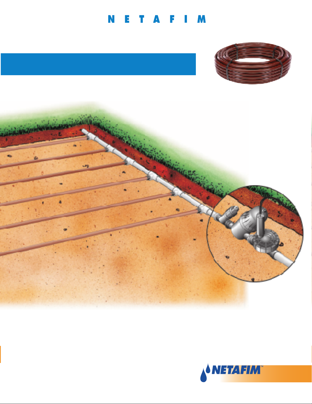
Techline® CV Design Guide
Subsurface or On-Surface
Pressure Compensating Dripperline
with Check Valve
Page 2

N E T A F I M T E C H L I N E® C V D E S I G N G U I D E
TABLE OF
CONTENTS
INTRODUCTION
Overview ....................................................................................................................... 3
DESIGN CRITERIA
Site Survey ................................................................................................................... 4
Point of Connection ...................................................................................................... 4
BASIC DESIGN STEPS
When Should You Use Techline CV ..............................................................................
Choosing the Proper Techline CV ................................................................................ 5
Techline CV General Guidelines Chart ......................................................................... 5
Types of Layouts .......................................................................................................... 6
"GRID" Layout .............................................................................................................. 6
"Lite" Layout ................................................................................................................. 6
What Do These Layouts Have in Common? ................................................................ 6
Basic Grid Layout ......................................................................................................... 7
Basic Lite Layout .......................................................................................................... 7
How to Calculate Equal Techline CV Row Spacing ...................................................... 7
Length of Techline CV Rows ........................................................................................ 8
Techline CV Maximum Length of Laterals Chart .......................................................... 8
Center Feed Grid Layouts ............................................................................................ 8
Other Grid Layout Considerations ............................................................................... 9
Zone Water Requirements .......................................................................................... 10
Techline CV Flow per 100' Chart ................................................................................ 10
Fittings ........................................................................................................................ 11
Staples ....................................................................................................................... 11
Line Flushing Valves ................................................................................................... 11
If An Automatic Line Flushing Valve is Desired .......................................................... 12
If An Automatic Line Flushing Valve is Not Desired ................................................... 12
Air/Vacuum Relief Valves ............................................................................................ 13
Filters .......................................................................................................................... 14
Pressure Regulating Valves (PRV’S) ........................................................................... 14
Low Volume Control Zone - Low Flow ....................................................................... 15
Low Volume Control Zone - High Flow ...................................................................... 15
Slopes and Berms ...................................................................................................... 16
Techline Check Valve .................................................................................................. 16
Trees ........................................................................................................................... 16
Pressure & Flow Checks ............................................................................................ 17
Calculating Precipitation Rates .................................................................................. 17
5
1
Page 3

2
N E T A F I M T E C H L I N E® C V D E S I G N G U I D E
N E T A F I M T E C H L I N E® C V D E S I G N G U I D E
TABLE OF
CONTENTS
(continued)
TECHLINE CV IN TURF
Techline CV in Turfgrass ............................................................................................. 18
Where and Why to Use Techline CV in Turf ................................................................ 18
Tips for Using Techline CV in a Newly-Sodded Lawn ................................................ 19
SPECIAL APPLICATIONS AND TIPS
Parking Lot Islands ..................................................................................................... 20
Electrical Grounding ................................................................................................... 20
Techline CV Above and Below Grade ........................................................................ 20
TECHLINE CV WINTERIZING INSTRUCTIONS
Techline CV Winterizing Instructions ..........................................................................
Manual Winterization .................................................................................................. 21
Compressed Air Winterization .................................................................................... 21
TECHLINE CV TECHNICAL DATA
Applications, Specifications and Features/Benefits ...................................................
Exploded View of Techline CV Dripper from Above and Below ................................. 23
Design Formulas ........................................................................................................ 24
Specifications ............................................................................................................. 25
Techline CV Application Rate Tables .......................................................................... 26
Techline CV General Guidelines ................................................................................. 27
Techline CV Maximum Length of a Single Lateral ...................................................... 27
Techline CV Flow ........................................................................................................ 27
Disc Filter Sizing ......................................................................................................... 28
Techline CV with Techfilter .......................................................................................... 29
Techfilter Installation and Mounting Instructions ........................................................ 29
Techfilter Use and Replacement Guidelines .............................................................. 29
Techfilter Specifying Information ................................................................................ 30
Techline CV Minimum & Maximum Feet for Each Filter Size ..................................... 30
Techfilter with Techline CV Model Number Descriptions ........................................... 31
Techline CV End Feed Layout .................................................................................... 34
Techline CV Center Feed Layout ................................................................................ 35
21
22
Installation Checklist ......................................................................................... 36
System Inspection Checklist ........................................................................... 37
Fittings ..................................................................................................................... 38
MOST FREQUENTLY USED CHARTS
Techline CV General Guidelines .................................................................................
Techline CV Maximum Length of a Single Lateral ...................................................... 39
Techline CV Flow ........................................................................................................ 39
39
Page 4
3
N E T A F I M T E C H L I N E® C V D E S I G N G U I D E
INTRODUCTION
This manual covers the basics of design, installation, and maintenance of Techline CV integral
dripperline. Included are design steps, technical data, design layouts, as well as some design and
installation details and checklists using both the “Grid” and “LITE” layout methods.
OVERVIEW:
• Netafim is the world leader in low volume irrigation. Since the early 1960ʼs Netafim has pioneered
the science of subsurface, on-surface and point source irrigation and manufacturing. Serving
more than 100 countries worldwide, Netafim products are sold into the Landscape & Turf market,
as well as agriculture, greenhouse and nursery, wastewater, mining and forestry.
• The Techline family of products have been used successfully in landscape since 1987 in North
America. Techline CV allows for even more water conserving designs because check valves are
built into every dripper.
• Landscape Architects, Contractors, Nurserymen, Designers and Consultants recognize the
benefits of using low volume and drip irrigation for new plantings because of its accelerated plant
growth compared to overhead spray and rotor irrigation. Coupling the rapid growth with dramatic
water savings and low volume irrigation becomes an important part of any irrigation system.
• With the flexibility and quality of Netafim products, architects, designers, and contractors have
highly sophisticated solutions to client and installation issues by bringing drip and subsurface
components together to grow plants, trees, shrubs, groundcover, and yes, even turf.
Page 5
4
N E T A F I M T E C H L I N E® C V D E S I G N G U I D E
N E T A F I M T E C H L I N E® C V D E S I G N G U I D E
DESIGN
CRITERIA
• Designing with Techline CV follows the same basic rules as designing with Techline, sprays and rotors.
• Point of connection, static and operating pressures, flow rates, and type of materials being irrigated are
the same.
• Designing similar areas into a zone and not mixing products with different application rates is just like
sprinkler design.
• The essential differences include knowing the type of soil you are working with, and the method of
layout you use in the design.
SITE SURVEY:
• Obtain or draw a scaled plan of the site to be irrigated. Identify all slopes on the plan.
• Identify the type of soil (sand, loam or clay).
• Determine types of materials to be irrigated, turf, groundcover, shrubs, plants, and trees.
POINT OF CONNECTION:
• Type of water, potable, well, pump, effluent, etc.
• Pressure & volume available - Static and operating tests.
Note: For Techline CV Technical Product Application & Specifications, see page 22.
Page 6
5
N E T A F I M T E C H L I N E® C V D E S I G N G U I D E
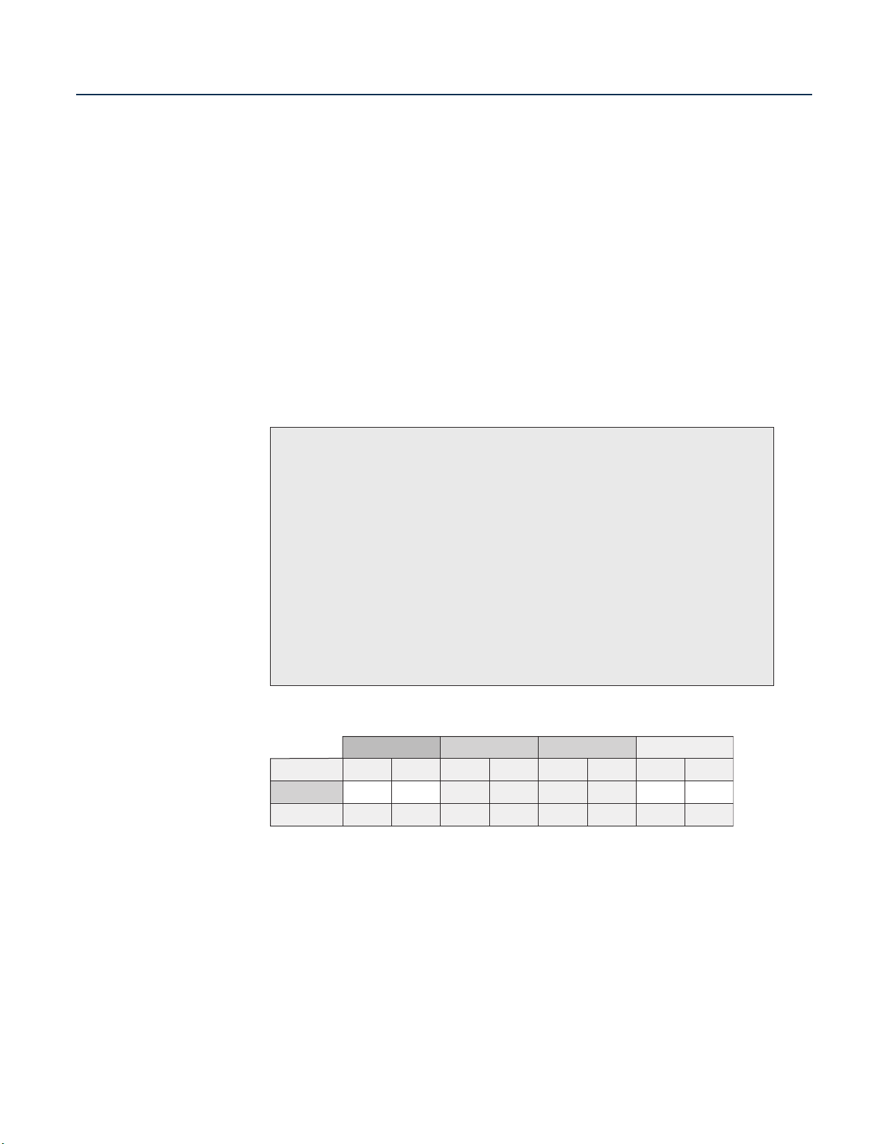
BASIC
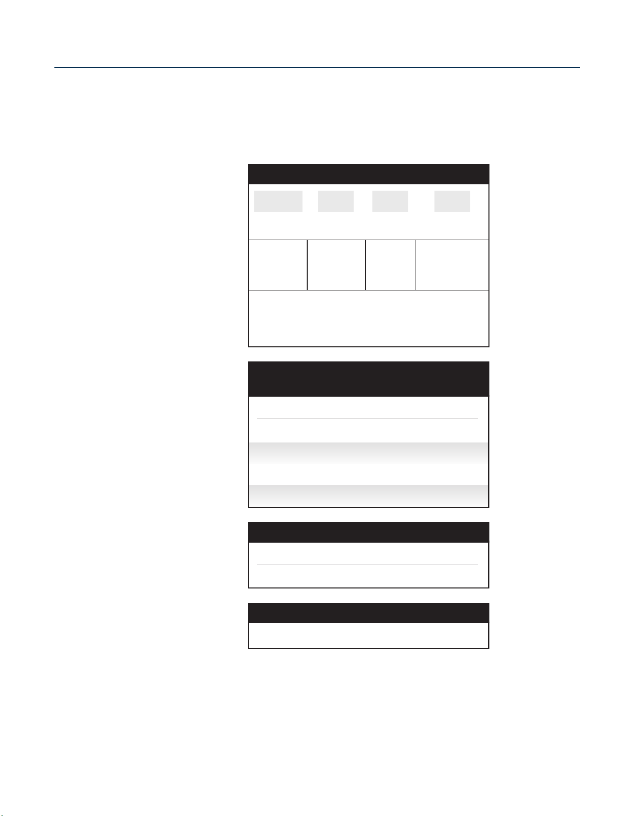
Dripper Flow
Dripper Interval
Lateral (Row) Spacings
Burial Depth
Application Rate (in./hr.)
Time to Apply 1/4"
of Water (in minutes)
Clay Soil
0.26 GPH
18"
18" - 22"
.19 - .15
79 - 100
Loam Soil
0.4 GPH
12"
18" - 22"
.43 - .35
35 - 43
Sandy Soil
0.6 GPH
12"
12" - 16"
.96 - .72
16 - 21
Clay Soil
0.26 GPH
18"
18" - 24"
.19 - .14
79 - 107
Sandy Soil
0.6 GPH
12"
16" - 20"
.72 - .58
21 - 26
Loam Soil
0.4 GPH
18"
18" - 24"
.29 - .21
52 - 71
SHRUB and GROUND COVERTURF
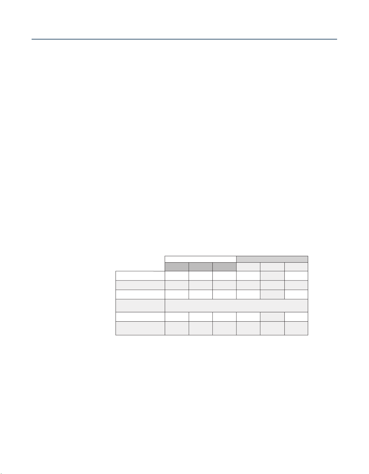
TECHLINE® CV General Guidelines
Maximum spacing recommendations: Following these spacing guidelines, dripper flow selection can be increased if desired by the designer.
On-surface or bury evenly throughout the zone to a maximum of 6 inches
DESIGN
STEPS
WHEN SHOULD YOU USE TECHLINE CV?
• Anytime you want to create an even wetted pattern of water throughout an area.
• Since the object of sprinklers is also to create an even wetted pattern, you can use Techline CV
anytime you can use sprinklers.
CHOOSING THE PROPER TECHLINE CV:
• From Table 1, answer two questions:
1. Are you irrigating a Shrub & Groundcover area or Turf?
2. Is the soil Clay, Loam or Sandy?
• Follow the proper column listed under TURF or SHRUB & GROUNDCOVER to identify the proper
Techline CV. Example - If you choose Shrub & Groundcover, with loam soil, 0.4 GPH/18” Techline CV is
the proper choice. (Each dripper will deliver 0.4 GPH and the drippers, mounted inside the tubing, are
spaced 18” apart.)
• What other information is in the General Guidelines Chart?
1. How far to spread out the laterals is listed on the “Lateral (Row) Spacings” line.
(For this example, rows should be evenly spaced anywhere from 18” - 24” apart.)
2. The corresponding application rates and time to apply are listed under the Lateral Spacings
line. (With rows of 0.4 GPH/18” Techline CV every 18” apart, the application rate is 0.29 inches
1
per hour and it will take 52 minutes to apply
rate is 0.21 inches per hour, and it will take 71 minutes to apply
/4” of water. If the rows are 24” apart, the application
1
/4” of water. For other row
spacings, see page 26.)
TABLE 1
Page 7
6
N E T A F I M T E C H L I N E® C V D E S I G N G U I D E
N E T A F I M T E C H L I N E® C V D E S I G N G U I D E
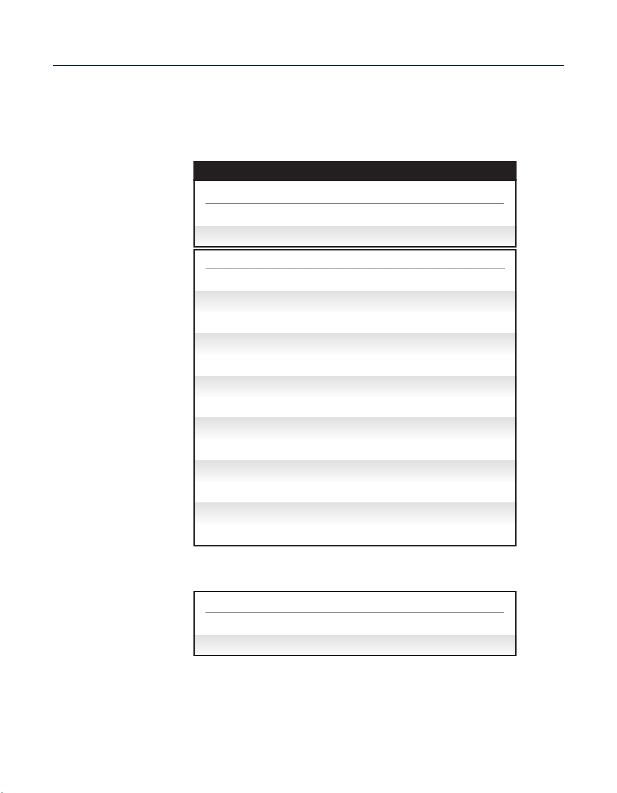
BASIC
Exhaust Header
Supply Header
TECHLINE CV
DESIGN
STEPS
(continued)
TYPES OF LAYOUTS:
There are two layout methods we recommend - “GRID” and “LITE”. Both accomplish the same goal, but
one method will be the preferred method based on what and how you are irrigating.
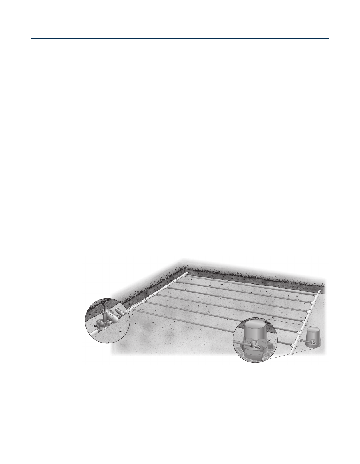
Basic Techline CV Grid Layout
“GRID”:
• This is the preferred method for installing Techline CV subsurface
• This method uses supply and exhaust headers with rows of Techline CV connected at each end
• The Supply Header delivers water to each row of Techline CV
• The Exhaust Header forms a continuous loop, or return leg, so all rows of Techline CV are being
supplied from both ends
• This interconnection of the piping network comprises the term “Grid layout.” This evens out the flow,
helps ensure water is being delivered downstream of any break in the laterals, and allows for much
easier repairs of any line breaks.
Basic Techline CV Lite Layout
“LITE”:
• The LITE layout is used exclusively on-surface
• It is the fastest and easiest layout method because no supply and exhaust headers are used
• The dripperline simply weaves back and forth throughout the zone in evenly spaced rows.
WHAT DO THESE LAYOUTS HAVE IN COMMON?
• Both methods assume even row spacings will be maintained
• Both methods are designed to flow water in a loop manner
Page 8
7
N E T A F I M T E C H L I N E® C V D E S I G N G U I D E
TECHLINE CV
2" to 4" Setback from Edge
5' 52"
BASIC
DESIGN
STEPS
(continued)
BASIC “GRID” LAYOUT:
• Headers should be indented 2” - 4” from hardscapes and planting areas.
• Headers may be PVC, polyethylene or in zones under 5-GPM, Techline CV or Techline CV Blank
Tubing.
• Headers must be sized to accommodate the flow of the zone without exceeding 5 feet per second
velocity. (Zone Water Requirement calculations are on page 10).
• Start rows of Techline CV 2” - 4” away from the edge of hardscapes, and move across the area with
equal row spacing that does not exceed the recommendations of Table 1.
provide enough moisture to prevent heat damage to plant material generated by hardscapes such as
asphalt). Start rows about 4” away from planting beds.
BASIC “LITE” LAYOUT:
• Water being supplied to the zone is split with a Techline fitting into two directions.
Use a TL075FTEE or TL2W075MA fitting.
• Weave the Techline CV back and forth throughout the planting area with evenly spaced rows.
• Indent the tubing 2” - 4” from hardscapes and planting areas.
• Because water is being split into two separate paths that meet in the middle, the maximum length of the
lateral can be twice the stated limit in Table 2.
• Therefore, to determine the maximum amount of Techline CV you can use in the zone, simply double
the maximum length stated in Table 2.
(The 2” setback will help
NOTE
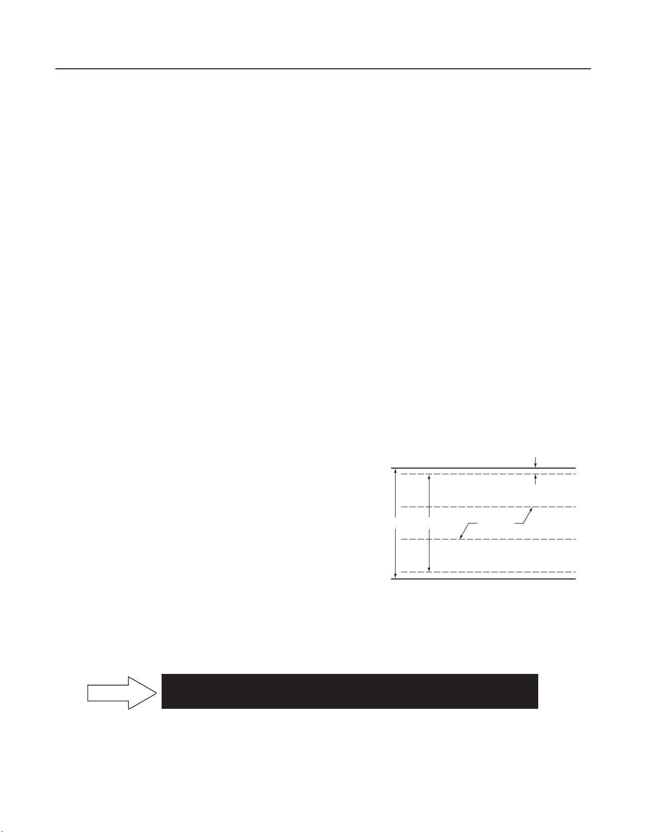
How to Calculate Equal Techline CV Row Spacing
Example:
• 5 feet x 12 inches = 60 inches
• 60 inches - 8 inches (2 edges x 4” setback) = 52”
• Following recommended Techline CV Row Spacing
for this example, assume 18 inches from Table 1
• 52” ÷ 18” = 2.89 spaces between Techline CV rows
• 2.89 is not a whole number, so round up to the next
whole number, which is 3 (spaces)
• Add 1 (one) to the number of spaces to determine
the number of Techline CV rows
• Determine equal spacing between Techline CV rows. 52 inches ÷ 3 = 17.3 inches
HOW TO QUICKLY DETERMINE THE AMOUNT OF TECHLINE CV IN A ZONE
(Square Footage of Zone x 12) ÷ Minimum Recommended Row Spacing
Page 9
8
N E T A F I M T E C H L I N E® C V D E S I G N G U I D E
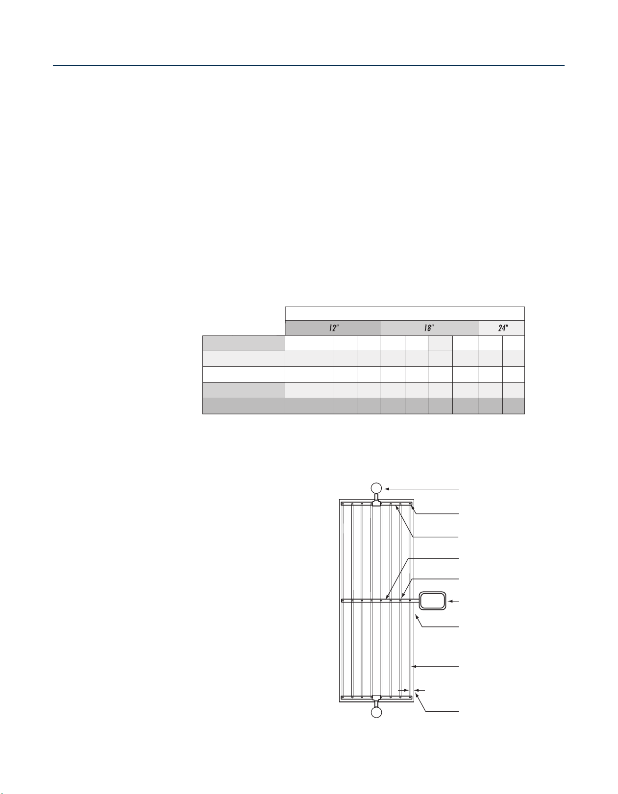
N E T A F I M T E C H L I N E® C V D E S I G N G U I D E
BASIC
Manual Line Flushing Valve
Plumbed to PVC or Poly
Techline Start Connection
Male Adapter
Remote Control Valve with
Disc Filter and PRV
Techline® CV Tubing Lateral
PVC or Poly Exhaust Heade
r
LF
LF
Techline Start Connection
PVC or Poly Supply Header
Area Perimeter
Perimeter Laterals
2" to 4" From Ed
g
e
109
325
409
469
0.4
86
256
322
369
0.6
127
427
539
618
0.26
65
194
244
280
0.9
151
459
579
664
0.4
91
274
346
397
0.9
152
458
580
666
0.6
116
348
440
506
0.9
15
25
35
45
Dripper Flow Rate (GPH)
INLET PRESSURE (psi)
120
361
456
523
0.6
177
604
763
877
0.26
TECHLINE CV DRIPPER SPACING
TECHLINE® CV Maximum Length of a Single Lateral (feet)
DESIGN
STEPS
(continued)
LENGTH OF TECHLINE CV ROWS:
• As with overhead irrigation, friction losses through pipe determine how long a length of pipe can be.
• You do not need to go through friction loss calculations for Techline CV laterals. It has already been
done for you.
• Table 2 shows the maximum length of a single Techline CV lateral within a zone.
• The chart also determines what the operating pressure of the zone needs to be. Example - If you
have a 322ʼ lateral of 0.6 GPH/12” Techline CV, it will need 35 psi to operate properly. If it is from
323ʼ- 369ʼ, it will need 45 psi. Note: We will discuss how to regulate your pressure in the Pressure
Regulating Valve section on page 14.
• Once the zone is laid out, note the pressure you will need somewhere on the design. We will need
this information later to size the Pressure Regulating Valve.
TABLE 2
CENTER FEED GRID LAYOUTS:
• You can increase the length of
laterals by center-feeding the zone.
By doing so, you can have a length
of Techline CV as called out in Table
2 going in each direction, effectively
doubling the maximum lateral
length. This is just like we discussed
with the LITE layout on page 6.
• Where layout flexibility exists,
Center Feed layouts are an
excellent design method.
• They allow for the most even flow of
water through the zone.
• They are an excellent option for
median strips and other large,
homogenous areas.
Techline CV
Center Feed Layout
Page 10
9
N E T A F I M T E C H L I N E® C V D E S I G N G U I D E
BASIC
Exhaust Header
Supply Header
Check longest
lateral agains
t
Table 2 for
maximum
lateral length.
Exhaust Header
Supply Heade
r
Total the combined
length of these
Techline CV laterals
and compare it
against the maximum
lateral length allowed
in Table 2.
Techline fittings
and dripperline
PVC or
Poly Piping
DESIGN
STEPS
(continued)
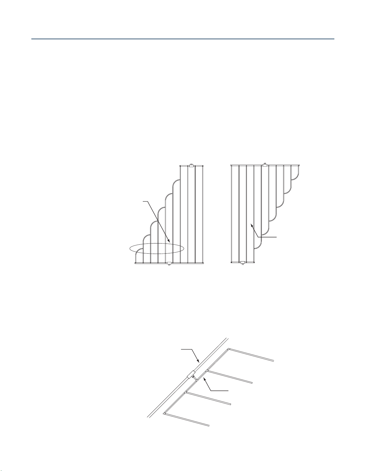
OTHER GRID LAYOUT CONSIDERATIONS:
• When branching out or joining rows of Techline CV, one of two rules apply:
Rule #1: When branching out Techline CV from the supply header, add up all “branched out”
dripperline and check it against the maximum lateral length listed in Table 2.
Rule #2: When joining laterals from the supply header, check only the longest lateral against the
maximum allowable in Table 2.
Branching Out
Techline CV Laterals
• To reduce the number of glue joints, saddles or insert fittings in a header, transition to Techline CV
and Techline fittings to make up subheaders.
• Make sure to follow the guideline of not exceeding 5 GPM in the “sub-header” zone.
Techline CV Laterals
Joining
Creating Sub-Headers to
Reduce Glue/Saddle Joints
Page 11
10
N E T A F I M T E C H L I N E® C V D E S I G N G U I D E
N E T A F I M T E C H L I N E® C V D E S I G N G U I D E
BASIC
0.26 GPH Dripper 0.9 GPH Dripper
26.40 GPH
17.58 GPH
Not Available
0.44 GPM
0.29 GPM
Not Available
0.4 GPH Dripper
40.OO GPH
26.67 GPH
Not Available
0.67 GPM
0.44 GPM
Not Available
61.00 GPH
41.00 GPH
31.00 GPH
92.00 GPH
61.00 GPH
46.00 GPH
1.53 GPM
1.02 GPM
0.77 GPM
12"
18"
24"
0.6 GPH Dripper
1.02 GPM
0.68 GPM
0.51 GPM
TECHLINE® CV Flow
(per 100 feet)
DRIPPER SPACING
DESIGN
STEPS
(continued)
ZONE WATER REQUIREMENTS:
• Once the Techline CV is laid out, we need to identify total zone flow. This will help determine
mainline, submain as well as supply and exhaust header sizing, valve, filter, and pressure regulator
selection.
• There are two ways to determine the flow in a Techline CV zone.
• Because Techline CV is pressure-compensating, the flow rate per 100' is the same over a wide
pressure range.
• Table 3 shows an easy way to determine total zone flow:
– Add up the amount of Techline CV
(in hundreds of feet) and
– Multiply that figure by the corresponding dripperline GPM to determine zone flow.
Calculating Total Zone Water Demand
• Multiply Total Feet x 12” = Total inches of Techline CV
• Total Inches of Techline CV ÷ Dripper Spacing = Number of Drippers
• Multiply Number of Drippers x Dripper Flow Rate (GPH) = Total GPH Flow
• Total GPH Flow ÷ 60 = Total GPM in the Zone
Example:
Ten 100ʼ rows of Techline CV with Dripper Spacing of 18”, Flow Rate is 0.6 GPH.
100ʼ x 10 = 1,000ʼ
1,000ʼ x 12” = 12,000” 12,000” ÷ 18” = 667 Drippers
667 Drippers x 0.6 GPH = 400 GPH Total Flow
400 GPH ÷ 60 = 6.67 GPM Flow in the Zone
TABLE 3
Page 12
11
N E T A F I M T E C H L I N E® C V D E S I G N G U I D E
BASIC
DESIGN
STEPS
(continued)
NOTE
TL075MA
3/4" Male
Adapter
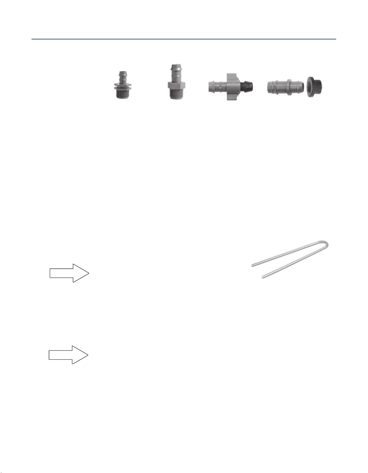
FITTINGS:
When laying out Techline CV, you will need to use fittings. If you have chosen a GRID layout, you may
need a transition fitting from the supply piping to the Techline CV. Further, you will use Techline CV
fittings to connect the rows of Techline CV to the headers. If you are using a LITE layout, you will also
use a transition fitting from the supply piping, as well as a fitting at the end or midpoint of the zone so
that a flush point can be installed.
Netafim 17mm barbed insert fittings are designed to speed the installation as well as offer you a broad
range of choices, (see page 38).
The barbed end(s) of all Techline CV fittings is raised and sharp. This allows the fitting to be used with
operating pressures up to 50-psi without clamps. If pressures are expected to exceed 50-psi, a clamp
is recommended. Ensure that the clamp is secured over the raised barb.
Fittings are simply pressed into the tubing. No special tools are required. As with all polyethylene pipe,
do not heat the tubing before inserting the fittings. It is not necessary and it can damage the pipe.
STAPLES:
Techline CV staples (TLS6) are used to hold dripperline in place.
While most commonly used when Techline CV is laid on-surface
or under a mulch cover, staples are also valuable when a layout
is being assembled sub-grade before being covered with dirt.
Rule of Thumb: Use a minimum of one staple for every:
• 3 feet of dripperline in sand
• 4 feet of dripperline in loam
• 5 feet of dripperline in clay
Further, use 2 staples “xʼed” over each other with any change-of-direction fittings such as tees, elbows
or crosses.
TL050MA
1/2" Male
Adapter
TLIAPE
TLIAPVC
TLS6
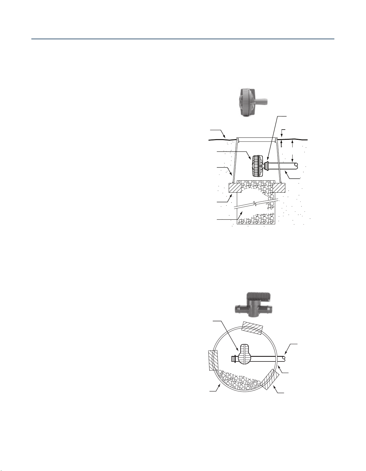
LINE FLUSHING VALVES:
NOTE
Techline CV has a check valve in each dripper designed to hold back a 41/2 foot column of water (2-psi
dripper closing pressure). Therefore, it may not be desirable to use an automatic Line Flushing Valve with
Techline CV, since it could allow water to drain from the dripperline after zone shutdown.
• Line Flushing Valves are used to provide a cleansing action in dripperline each time the zone is turned
on.
• When the zone is turned on, the flush valve begins dumping water into a sump located under it.
• The dumping of water (additional flow) allows the velocity of water inside the dripperline to increase
momentarily helping to clean the inside walls of the tubing.
• This action moves sediments out of the zone and into the sump.
Page 13
12
N E T A F I M T E C H L I N E® C V D E S I G N G U I D E
N E T A F I M T E C H L I N E® C V D E S I G N G U I D E
BASIC
Techline Shut-Off
Valve #TLSOV
(blank tubing may be
attached to outlet)
Techline CV Lateral
(or Exhaust Header
)
Valve Box
(Install Per Specs)
Brick Supports
(Three)
3/4" Gravel Sump
(1 Cubic Foot)
Compression Ring
(Provided)
1"
See Specs
Techline
17mm Tubin
g
Finish Grade
Valve Box
(see specs)
Brick Supports (3)
3/4" Gravel Sump
(1 cubic foot)
Line Flushing
Valve (TLFV-1)
DESIGN
STEPS
(continued)
IF AN AUTOMATIC
LINE FLUSHING VALVE IS
DESIRED:
• It is because the desire to have
a cleansing action outweighs the
desire to hold the water inside
the tubing when the zone is off.
• As such, place a Line Flushing
Valve (one per each 15 GPM
of zone flow) as far away from
the source as possible. This will
typically be somewhere along
the exhaust header in a GRID
layout and at the midpoint of the
tubing in a LITE layout.
• When Center Feed layouts are
used, install at least one Line
Flushing Valve on each exhaust
header.
• Line Flushing Valves should
be buried in a valve box with a
gravel sump adequate to drain
approximately one gallon of
water.
• See Air/Vacuum Relief Valves on
page 13.
Netafim Line Flushing Valve
IF AN AUTOMATIC LINE
FLUSHING VALVE IS
NOT DESIRED:
• It is because holding the
water in the Techline CV is
desired and,
• Procedures have been
established to manually
flush the lines during the
season.
• In this case, Techline
Shut-Off Valves
Figure 8 Line Ends (TLFIG8)
should be located along the
exhaust header, or at the
midpoint of a LITE layout.
(TLSOV) or
Techline CV Manual Line
Flush Valve
Page 14

13
N E T A F I M T E C H L I N E® C V D E S I G N G U I D E
Techline Start
Connection
Line Flushing Valve Plumbed to PVC,
Poly or Techline CV
Area Perimeter
Techline CV Lateral Tubing
Blank Tubing
Centered on mound
or berm
Supply Header
Remote Control Valve
with Disc Filter and PRV
Exhaust
Header
Techline Tee
Air/Vacuum Relief Valve
(Plumbed to Techline CV,
one at each high point)
LF
AR
6" Round Valve Box
Air/Vacuum Relief Valve
Techline 180 2-Way
Adapter Tee - TL075FTEE
3/4"M x 1/2"F
Reduction Bushing
Finish Grade
Techline CV Tubin
g
3/4" Crushed
Gravel Sump
Brick Supports (3)
BASIC
DESIGN
STEPS
(continued)
NOTE
NOTE
AIR/VACUUM RELIEF
VALVES:
Because Techline CV is designed
to keep water in the tubing, an
A/VRV would only be used in
conjunction with an automatic
Line Flushing Valve as described
in the previous section.
If you want to hold the water
inside the dripperline after
zone shutdown, (you are using
a TLSOV or FIG8 in lieu of an
automatic Line Flushing Valve)
disregard this section.
An Air/Vacuum Relief Valve
freely allows air into a zone
VRV)
after shutdown. It also ensures
a vacuum doesnʼt draw debris
into the dripperline. Further, they
also provide a means of releasing
air from the dripperline when the
zone is turned on, thus eliminating
air pockets and speeding up
dripperline operation. (Because
water stays in a Techline CV zone
anytime the elevation across the
zone is less than
not an issue).
• On zones where an Air/Vacuum
Relief Valve is desired, they are
installed at the highest point(s) in
the zone.
• To ensure that all of the
rows of the dripperline can
take advantage of the Air/
Vacuum Relief Valve,
it/them along a lateral that
runs perpendicular to the
dripperline laterals. This may
be an exhaust header, or a
special lateral connecting all
the rows of dripperline, such as
going over a berm.
In large scale irrigation systems
where pumps and large diameter
pipe are used, air that has been
created must be expelled. As
such, the use of Continuous
Air Vents may be required
on continuously and noncontinuously pressurized lines.
41/2
(A/
feet, this is
install
Netafim Air/Vacuum
Relief Valve (TLAVRV)
Installing A/VRV
To Laterals
Page 15
14
N E T A F I M T E C H L I N E® C V D E S I G N G U I D E
N E T A F I M T E C H L I N E® C V D E S I G N G U I D E
BASIC
DESIGN
STEPS
(continued)
FILTERS:
• Just like overhead irrigation, dripperline needs protection against dirt and debris. (In sprinkler heads,
filters are placed under the drive assembly or nozzle. With drip and dripperline, one filter is placed at
the beginning of the zone, or at the POC).
• Filters are normally installed immediately downstream of the remote control valve.
• Netafim uses a non-collapsing stack of flat grooved discs that effectively capture contaminants.
• They are easily removed from the filter body and flushed clean under a faucet or in a pail of clean
water.
• Disc filters come in a variety of sizes and filtering capacities.
• Rule of Thumb: Use 120 or 140 mesh filters for Techline CV designs. Techline CV only requires 120
mesh filtration. If a finer mesh filter is used, it may require more frequent cleanings.
• Refer to “DISC FILTER SIZING CHART” on page 28 to properly size the filter.
PRESSURE REGULATING VALVES (PRV’S):
Pressure Regulating Valves reduce the operating pressure so that Techline CV zones operate
between 15 and 45 psi.
• PRVʼs are normally installed immediately downstream of the disc filter and remote control valve.
Often all three components are in the same valve box, and the distance from the PRV to the Techline
CV is limited so additional friction is not incurred.
3
• The two most popular sizes of PRV are both
range of 0.25 - 4.4 GPM. The
from
11/2
" - 3” are also available for zones with flows up to 200 GPM.
• To select the correct PRV, choose the model that has the correct flow range based on total zone flow.
• Then select the correct pressure rating based on the following:
1. If you used the “Maximum Length of a Single Techline CV Lateral” chart, (Table 2) match the PRV
to the same pressure rating you used for your maximum lateral length calculation,
OR
2. Simply use a 45 psi PRV. (Because Techline CV is pressure-compensating, there is no reason to
intentionally reduce the pressure below 45 psi).
NOTES:
1. If the PRV is remotely located from the supply header, remember to account for any friction loss
that occurs through the piping to the supply header.
2. Low Volume Control Zone Kits:
• These preassembled kits speed installation and have all of the components needed for a low
volume zone.
• Kits are sized for a specific flow range
High Flow version has a flow range of 3.5 - 17.6 GPM. Other sizes
/4" units. One is a Low Flow version that has a flow
Page 16

15
N E T A F I M T E C H L I N E® C V D E S I G N G U I D E
BASIC
DESIGN
STEPS
(continued)
LOW VOLUME CONTROL ZONE - LOW FLOW
LVCZ10075-LF
• Hunter 24VAC PGV-100JT-G 1” valve
• Netafim DF075-140 Filter
• Netafim PRV075LF45V2K PRV
• For zones ranging from 0.25 - 4.4 GPM
Low Volume
Control Zone Kit
(LVCZ10075-LF)
0.25 - 4.4 GPM
Flow Selection for PRV
Low Flow PRV Operates from
0.25 to 4.4 GPM
LOW VOLUME CONTROL ZONE - HIGH FLOW
LVCZ10075-HF
• Hunter 24VAC PGV-100JT-G 1” valve
• Netafim DF070-140 Filter
• Netafim PRV075HF45V2K PRV
• For zones ranging from 3.5 - 17.6 GPM
High Flow PRV Operates from
3.5 to 17.6 GPM
Low Volume
Control Zone Kit
(LVCZ10075-HF)
3.5 - 17.6 GPM
Page 17

16
N E T A F I M T E C H L I N E® C V D E S I G N G U I D E
N E T A F I M T E C H L I N E® C V D E S I G N G U I D E
BASIC
PVC or Poly Supply Header,
(continues to next tree)
Estimated
Dripline of
Mature Tre
e
Valve, Filter
PRV Assembly
Tree Rootball
Techline CV Tubing
(dimensions per plans)
Line Flushing Valve
with Gravel Sum
p
LF
Techline® Tee
18" at Top
Up To
+25%
22 1/2" at Botto
m
2/3
1/3
DESIGN
STEPS
(continued)
SLOPES AND BERMS:
Taller Slope Irrigation Method
Techline CV has a check valve built into each
dripper. This allows the dripperline to hold
back up to a
41/2
feet column of water. As
such, designing Techline CV on slopes and
berms is very easy.
• Techline CV should be installed
perpendicular to (across) slopes
• In the upper 2/3 of the slope, space Techline
CV per TABLE 1, page 5, 27 or 39.
1
• In the lower
/3 of the slope, increase the
distance between rows by 25%.
• For every
41/2
feet of elevation change,
either:
- Split the slope into separate zones, or
- Install a Netafim “TLCV” inline check
valve.
Techline Check Valve (TLCV):
• Designed to hold back up to a 13ʼ column of water
• Rule of Thumb: Every 1ʼ of water exerts 0.433 psi of pressure at the base of the column.
As such, a 100ʼ column of water exerts 43.3 psi at the base.
TLCV Specifications:
• Flow Range: 0.9 - 4.4 GPM
(200 - 1,000 I/h)
• Closing Pressure: 5.7 psi (4m)
• Opening Pressure: 7.1 psi (5m)
• Can hold back a 13ʼ column of water (5.7 ÷ .433)
• Connection: 17mm insert
TREES:
• It is important to provide trees
Techline CV Tubing and
Accessories for Tree Planting
with adequate water at the
rootball, while also planning for
the treeʼs needs as it grows.
NOTE: When trees are
transplanted, the soil in the rootball
and the native soil are different.
You must ensure that there are
sufficient drippers irrigating both
soils because water will not
migrate from one soil type to the
other.
• A loop of Techline CV close to
the rootball, with more Techline
CV surrounding the estimated
dripline of the tree when mature
will provide sufficient water.
Page 18

17
N E T A F I M T E C H L I N E® C V D E S I G N G U I D E
BASIC
DESIGN
STEPS
(continued)
PRESSURE & FLOW CHECKS:
• One of the best means of ensuring a Techline CV zone is operating properly is to test the pressure at
regular intervals.
• By taking and recording the pressure while the zone is running, you can ensure that the zone is
working as installed.
• Take the reading as far away from the source as possible to ensure that pressures throughout the rest
of the zone are at least that high.
• If readings are lower than normal, a line break, clogged filter, dirty remote control valve, clogged PRV,
or reduced line pressure are possible causes.
NOTE: Always take the readings at the same time of day, from the same spot. This reduces the chance
of faulty readings due to other factors.
• If a water meter is available, check the flow of each zone.
• Record the information at least once per year on a “System Inspection Checklist” (an example is
provided on page 37).
CALCULATING PRECIPITATION RATES:
• Method 1: See the “Techline CV Application Rate Tables” on page 26.
• Method 2: If there is some variation in your design, (for instance, when we had to decrease the
distance between the rows in our earlier example) then rely on the formula below.
CAUTION: Though the precipitation rates of rotors, fixed sprays and Techline CV can be very close in
many situations, we do not recommend tying dripperline into spray or rotor zones. Techline CV has an
irrigation application rate efficiency greater than sprays or rotors. Even when calculations make it appear
that the application rates are the same, a Techline CV zone will actually be delivering more water since
none of it is evaporating or landing where it canʼt be used.
Determining Techline CV Application Rate
Application Rate (inches per hour) =
231.1 x Dripper Flow Rate (GPH)
Dripperline Row Spacing (inches) x Techline CV Dripper Spacing (inches)
Example:
• Dripperline Row Spacing = 17.3” apart
• Techline CV Dripper Spacing = 18”
• Dripper Flow Rate = .6 GPH
231.1 x .6 (GPH)
17.3 inches x 18 inches
= .45 inches per hour
Page 19

18
N E T A F I M T E C H L I N E® C V D E S I G N G U I D E
N E T A F I M T E C H L I N E® C V D E S I G N G U I D E
TECHLINE CV
IN TURF
TECHLINE CV IN TURFGRASS:
Background: Netafim products have been used successfully in turfgrass since the 1980's. It is a
popular choice for a variety of residential and commercial general-use and specialized-use turf areas,
and has been used very successfully in sports turf, as well as composition and grass tennis courts.
WHERE AND WHY TO USE TECHLINE CV IN TURF:
• Long, odd-shaped or narrow areas:
– Allows greater landscape design freedom to use curvilinear layouts that cannot be utilized when
overhead irrigation is used
– Eliminates wet roads and sidewalks
– Helps save water
– Reduces slipping and tripping hazards
– Reduces wet surface hazards to vehicle traffic
– The ability to irrigate areas with less water in long narrow areas where either getting the water is
hard, or zoning the area is difficult
– Overspray is eliminated
• Areas close to buildings and at-grade windows:
– Stops windows from getting wet
– Allows the use of turfgrass close to a building without damage to facades
– Reduces deterioration and discoloration of building facades
• Athletic fields:
– No exposed sprinklers reduces impact injuries
– On tight-soil fields:
• Can be irrigated and softened prior to play without wetting the surface
• Helps reduce impact injuries from hard soil surfaces
– Because water window issues are eliminated, time of play increases
• Auto dealerships and other parking areas:
– No overspray reduces the cost of auto detailing
– Reduces slipping and tripping hazards
– Reduces wet surface hazards to vehicle traffic
• High wind, or constant wind areas:
– Overspray and wasted water is eliminated
– Water gets where it is supposed to be regardless of wind
• High liability areas:
– Tripping and other liability issues are significantly reduced
– Maintenance costs to repair broken sprinkler heads are greatly reduced
• Vandal-prone areas:
– “Out of sight, out of mind”
– Maintenance costs and potential liability of unrepaired problems is greatly reduced
Page 20

19
N E T A F I M T E C H L I N E® C V D E S I G N G U I D E
TECHLINE CV
IN TURF
• Wood hardscapes:
– Bleaching of hardscapes such as wooden fences is eliminated
– Aesthetics of the wood hardscapes is maintained
• Steep slopes:
– Allows turf to be used on slopes
– Water is easily managed on slopes with dripperline
– Wash outs are eliminated
• Locales where the cost of water is too expensive for overhead irrigation:
• Unlike spray or rotor irrigation, which does not have an even application rate across its pattern,
Techline CV has an extremely well-balanced application rate in the entire area. As such, you do not
need to overwater to make sure the driest area receives enough water.
– Techline CV uses about half of the water of an overhead system
– Techline CV is about 90% efficient vs. overhead irrigation, which is about 60% efficient
• Techline CV seals in 1.3 gallons of water for every 100', saving water from draining out of the
dripperline each time the zone shuts off.
• Water window issues:
– Irrigate whenever necessary because there is no exposed spray
• Recycled/reclaimed water or fertigation applications where spraying water is illegal:
– Allows for use of nutrient-rich water, often at a greatly reduced cost
– Saves potable water supplies
TIPS FOR USING TECHLINE CV IN A NEWLY-SODDED LAWN:
• Follow Table 1 General Guidelines recommendations for turf,
• Bury the Techline CV approximately 4” below final grade
• In areas where mechanical aeration will be used, bury the Techline CV 6” below final grade and
ensure aeration does not exceed 4"
• When installing the sod:
– It is important that the final grade is smooth, ensuring that the sod makes solid contact with the soil
– Properly “knit” the edges together
– Thoroughly wet the sod with overhead irrigation
– Roll the sod to ensure good contact
• If the irrigation system is automatic:
– Set the zone to run several times daily
– Keep wetted from above as necessary until the roots establish
• Once you cannot pull the edges of the sod up, discontinue overhead watering
• Irrigate on a daily or every-other-day basis
• Protection against root intrusion
– For years of trouble-free system performance, and a limited lifetime warranty against root intrusion,
use Netafim Techfilter with Techline CV,
see pages 29 - 33.
see pages 5, 27 or 39.
Page 21

20
N E T A F I M T E C H L I N E® C V D E S I G N G U I D E
N E T A F I M T E C H L I N E® C V D E S I G N G U I D E
SPECIAL
APPLICATIONS
AND TIPS
PARKING LOT ISLANDS:
If islands are small, consider tying several of them together on the same zone.
• Once you have determined that the conditions of the islands are similar enough to interconnect them,
design each for the same precipitation rate by using the same Techline CV and spacing.
• Use one Low Volume Control Zone kit at the source, and install a TLSOV or TLFIG8 either at the end
of the last island or, if the islands dead-end, on each island.
• Connections between the islands should be PVC, or as called out by the designer or local codes.
ELECTRICAL GROUNDING:
• The effectiveness of electrical grounding is dependent on the soil and its moisture content. In moist
soil, grounding is more effective than in dry soil.
• One method of ensuring moist soil is to install a length of Techline CV along a length of unclad
copper wire being used for grounding purposes. The Techline CV is installed in the usual method.
Run it from a separate station on the controller to give you maximum control.
• Techline CV can also be installed over the top of a grounding plate or ground rod.
TECHLINE CV ABOVE AND BELOW GRADE:
Techline CV is designed to be used in a variety of ways:
• It can be laid on the surface, (it’s UV resistant!) and held in place with Techline Staples (TLS6),
• It can be laid on the surface, stapled into place and covered with mulch, or
• It can be buried below grade.
NOTE: When using Techline CV above grade with staples, use enough staples to firmly hold the tubing
in place, especially in freezing climates.
Page 22

21
N E T A F I M T E C H L I N E® C V D E S I G N G U I D E
TECHLINE CV
WINTERIZING
INSTRUCTIONS
TECHLINE CV WINTERIZING INSTRUCTIONS:
Winterizing an irrigation system involves removing enough water to ensure that
components do not crack or break during freezing weather.
Because Techline CV is designed to keep water sealed inside the tubing between
irrigations, it is important that these simple steps be followed.
NOTE
MANUAL WINTERIZATION
• A drain port must be present at all low points in the zone.
• Ports may be a tee or elbow with a threaded plug, a Netafim TLFIG8 or TLSOV
which, when opened, will allow water to drain. If a Netafim “automatic” Line
Flushing Valve has been used, disassemble it.
• If the Techline CV zone is a grid or closed system, the supply and exhaust
headers may contain a significant amount of water because they are either blank
Techline CV tubing, PVC, or poly pipe. It is important to provide drain ports for
these components.
• If the Techline CV laterals dead-end, and are not connected to an exhaust header,
the lateral ends should be opened to drain at the lowest point(s).
• In the event that some water remains in the system, the disc filter should be
disassembled, and the discs removed to allow any water to exit. Leave the filter
disassembled in the event that some water remains in the system.
• In systems where elevation is a concern, install a drain port upstream of the filter to
ensure as much water as possible is drained.
• Follow manufacturer instructions for any automatic zone valves.
COMPRESSED AIR WINTERIZATION
Follow the same initial procedures for a Techline CV zone as you would for a zone of
overhead sprinklers.
Note: Techline CV fittings are rated to 50 psi without clamps, so the air pressure
must be adjusted according. It is air volume, not pressure that is effective when
winterizing in this manner.
• The pressure regulator, which is normally installed in the valve box along with
the zone valve and filter regulates water, not air pressure. Air pressure should be
regulated to 50 psi or less.
• The drain ports, (a fitting with a threaded plug, a Netafim TLSOV, TLFIG8, or
Netafim Line Flushing Valve), which are normally installed as far away from the
water source of the zone as possible, must be open. Unscrew and disassemble
any “automatic” Line Flushing Valves.
• With all drain ports open, compressed air should be applied until no water is seen
exiting the zone.
(no compressed air blow-out)
Page 23

22
N E T A F I M T E C H L I N E® C V D E S I G N G U I D E
N E T A F I M T E C H L I N E® C V D E S I G N G U I D E
TECHNICAL
DATA
Techline CV
Dripperline
APPLICATIONS:
• Subsurface or on-surface installations
• Slopes
• Curved, angular or narrow areas
• High traffic/high liability areas
• Areas subject to vandalism
• High wind areas
• Turf, shrubs, trees, flowers
• At-grade windows
• Sports turf
• Tennis courts
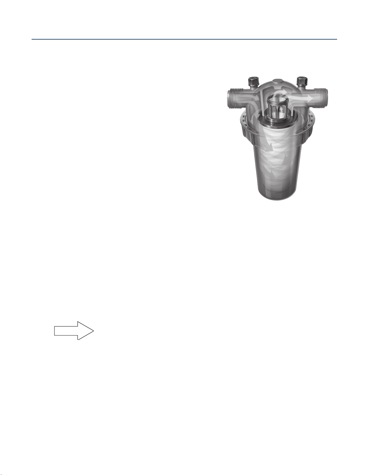
FEATURES/BENEFITS:
• Each Dripper has a built-in, 2 psi Check Valve:
- All drippers turn on and off at the same time
- Minimizes water loss
41/2
- Holds back up to
- No low drainage; great on slopes
- More precise watering - Entire lateral begins operating at the same time
• Built-in Physical Root Barrier: Drippers are protected from root intrusion without chemical reliance
• Dark Brown Color: Visually identifies Techline CV, better blending into surrounding colors of the
landscape
• Pressure Compensation: All drippers deliver equal flow across the length of the lateral
• Unique Flow Path: Turbonet technology allows for better control of water flow and less chance of
clogging
• Single hole dripper outlet from tubing:
- Better protection against intrusion
- Allows the dripperline to be used in subsurface applications without chemical protection
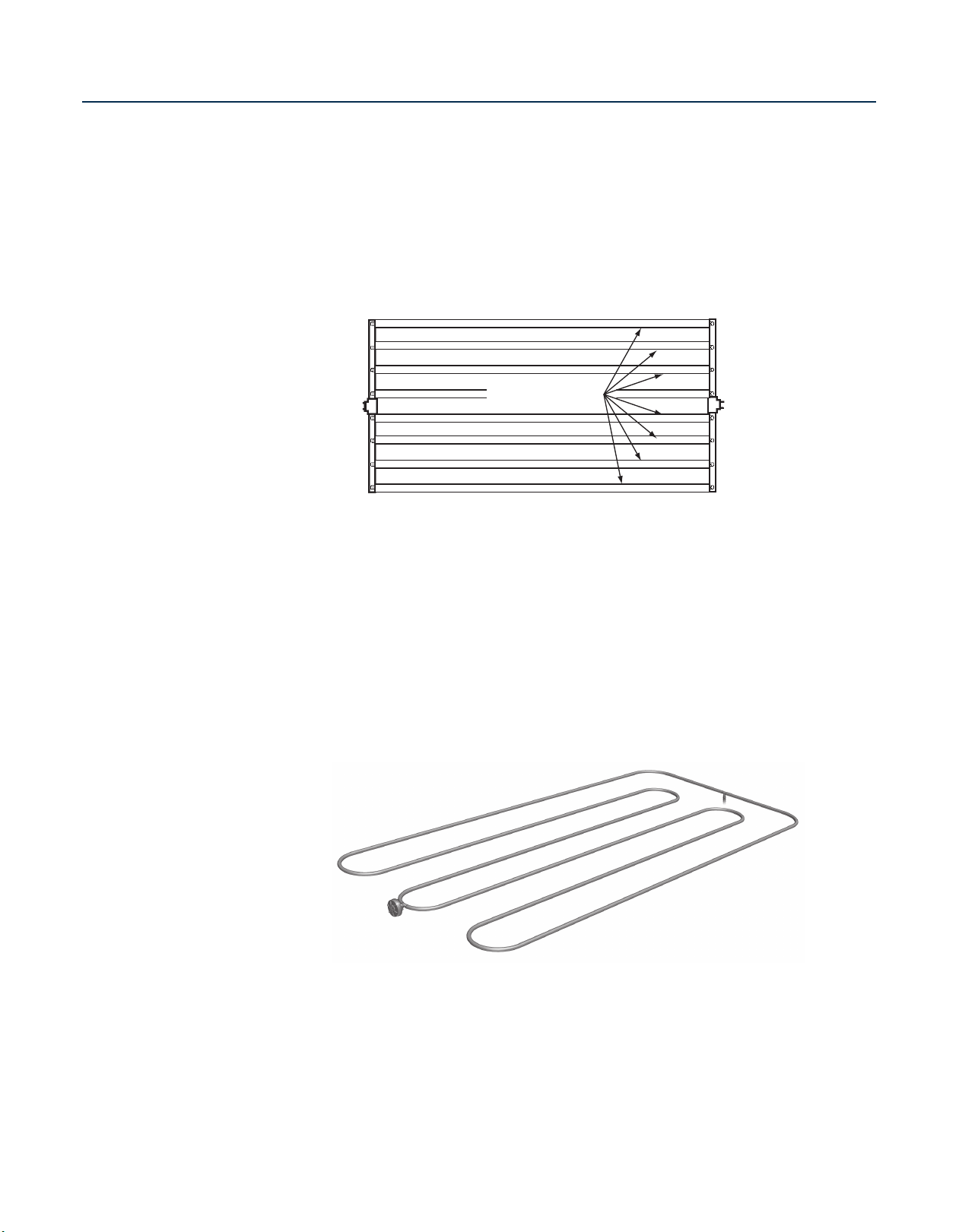
• Water is captured from the center of the tubing, ensuring that only the cleanest water is used
• No Air/Vacuum Relief Valve is required: Installations are faster and less expensive
• No Automatic Line Flushing Valve is required: Because the dripperline is designed to hold water in
the tubing after shut-down, a manual flush may be used
• Techline Compatible: Same ID/OD as Techline, works with all Techline fittings and no pipe clamps
are needed under 50 psi
• Installations are faster and less expensive
• Techfilter Compatible: Provides a limited lifetime warranty against root intrusion
feet of water
SPECIFICATIONS:
• Dripper Flow Rates
• Dripper Spacings:, 12", 18", 24" (24" is available in 0.6
& 0.9 GPH flow rates)
• Pressure Compensation Range: 14.7 to 70 psi
• Maximum System Pressure: 50 psi
• Tubing Diameter: 0.66” O.D., 0.56" I.D.
• Coil Lengths: 100', 250', 1,000'
(TLSOV or TLFIG8)
(GPH): 0.26, 0.4, 0.6, 0.9
Page 24

23
N E T A F I M T E C H L I N E® C V D E S I G N G U I D E
TECHNICAL
Labyrinth
Dripper Cover
Diaphragm
Raised lip surrounding the exit hole,
along with the air gap between the exit
hole in the dripper and the tubing,
provides physical root barrier.
Labyrinth
Dripper Cover
Diaphragm
Filtration Surfac
e
DATA
Techline CV – Exploded View of
Dripper from Above and Below
Above View
Below View
Page 25

24
N E T A F I M T E C H L I N E® C V D E S I G N G U I D E
N E T A F I M T E C H L I N E® C V D E S I G N G U I D E
TECHNICAL
DATA
DESIGN FORMULAS
Formula 1.1
Formula 1.2
Formula 1.3
Estimated Total Length of Dripperline =
Irrigated Area x 12
Minimum Recommended Lateral Spacing (inches)
In Which:
Estimated Total Length of Dripperline = Total Footage of Dripperline in a Zone
Irrigated Area = Total Area in Square Feet
Minimum Recommended Lateral (Row) Spacing = The minimum row spacing from the
General Guidelines Chart in inches
Application Rate (inches per hour) =
231.1 x Dripper Flow Rate (GPH)
Dripperline Row Spacing (inches) x Dripper Spacing (inches)
In Which:
Application Rate is = Inches per Hour of Water Being Applied
Dripper Flow Rate = Gallons per Hour Flow of One Dripper
Dripper Spacing = Spacing in Inches of Drippers Inside Tubing
Dripperline Row Spacing = Inches Between Techline CV Laterals (Rows)
Number of Drippers in a Zone =
Total Dripperline x 12
Dripper Spacing
In Which:
Number of Drippers = Number of Drippers
Total Dripperline = Length of All Dripperline in a Zone in Feet
Dripper Spacing = Spacing in Inches of Drippers Inside Tubing
Formula 1.4
Number of Drippers x Dripper Flow Rate (GPH)
In Which:
Flow per Zone = Total Gallons per Minute
Number of Drippers = Number of Drippers
Dripper Flow Rate = Gallons per hour of one dripper
GPH = Gallons per Hour Flow of One Dripper
Formula 1.5
(
Dripper Spacing (inches) x Dripperline Spacing (inches)
In Which:
Estimated Total Zone Flow = Gallons per Minute in Zone
Irrigated Area = Total Area in Square Feet
Dripper Spacing = Distance Between Dripperline in Inches
Dripperline Spacing = Distance Between Dripperline in Inches
Dripper Flow Rate = Gallons per Hour of One Dripper
Irrigated Area (square feet) x 144
Flow per Zone =
60
Estimated Total Zone Flow =
)
x Dripper Flow Rate (GPH) ÷ 60
Page 26
25
N E T A F I M T E C H L I N E® C V D E S I G N G U I D E
TECHNICAL
Dripper
Flow Rate
26 = 0.26 GPH
4 = 0.4 GPH
6 = 0.6 GPH
9 = 0.9 GPH
Dripper
Spacing
12 = 12"
18 = 18"
24 = 24"
Coil
Length
01 = 100 feet
025 = 250 feet
10 = 1,000 feet
Techline CV
Dripperline
TLCV
TLCV
X X
X X
X X
TECHLINE CV Specifying Information
For blank tubing use: TLCV010=1,000', TLCV0025=250', TLCV001=100'
Techline CV Ordering Example:
TLCV26-12025 is Techline CV, .26 GPH, 12" Spacing, 250' Coil.
TLCV010 is Techline CV Blank Tubing, 1,000' Coil.
TECHLINE CV Dripper Flow Passage
and Filtration Recommendations
Dripper Flow Depth Width Length Minimum Filtration
0.26 GPH 0.029" 0.033" 1.57" 120 Mesh
0.4 GPH 0.028" 0.050" 1.57" 120 Mesh
0.6 GPH 0.039" 0.050" 1.57" 120 Mesh
0.9 GPH 0.063" 0.045" 1.57" 120 Mesh
TECHLINE CV Tubing Dimensions
Inside Diameter Outside Diameter Wall Thickness
0.560" 0.660" 0.050"
TECHLINE CV Minimum Bending Radius
7 Inches
DATA
Specifications
Page 27

26
N E T A F I M T E C H L I N E® C V D E S I G N G U I D E
N E T A F I M T E C H L I N E® C V D E S I G N G U I D E
TECHNICAL
TECHLINE CV 0.4 GPH Dripper Flow
(in inches per hour)
Techline CV Row Spacing
Dripper Spacing 12" 13" 14" 15" 16" 17" 18" 19" 20" 22" 24"
12" 0.64 0.59 0.55 0.51 0.48 0.45 0.43 0.41 0.39 0.35 0.32
18" 0.43 0.40 0.37 0.34 0.32 0.30 0.29 0.27 0.26 0.23 0.21
TECHLINE CV 0.26 GPH Dripper Flow
(in inches per hour)
Techline CV Row Spacing
Dripper Spacing 12" 13" 14" 15" 16" 17" 18" 19" 20" 22" 24"
12" 0.42 0.38 0.36 0.33 0.31 0.29 0.28 0.26 0.25 0.23 0.21
18" 0.28 0.26 0.24 0.22 0.21 0.20 0.19 0.18 0.17 0.15 0.14
TECHLINE CV 0.6 GPH Dripper Flow
(in inches per hour)
Techline CV Row Spacing
Dripper Spacing 12" 13" 14" 15" 16" 17" 18" 19" 20" 22" 24"
12" 0.96 0.89 0.83 0.77 0.72 0.68 0.64 0.61 0.58 0.53 0.48
18" 0.64 0.59 0.55 0.51 0.48 0.45 0.43 0.40 0.39 0.35 0.32
24" 0.48 0.44 0.41 0.39 0.36 0.34 0.32 0.30 0.29 0.26 0.24
TECHLINE CV 0.9 GPH Dripper Flow (in inches per hour)
Techline CV Row Spacing
Dripper Spacing 12" 13" 14" 15" 16" 17" 18" 19" 20" 22" 24"
12" 1.44 1.33 1.24 1.16 1.08 1.02 0.96 0.91 0.87 0.79 0.72
18" 0.96 0.89 0.83 0.77 0.72 0.68 0.64 0.61 0.58 0.53 0.48
24" 0.72 0.67 0.62 0.58 0.54 0.51 0.48 0.46 0.43 0.39 0.36
DATA
Techline CV Application Rate Tables
Page 28

27
N E T A F I M T E C H L I N E® C V D E S I G N G U I D E
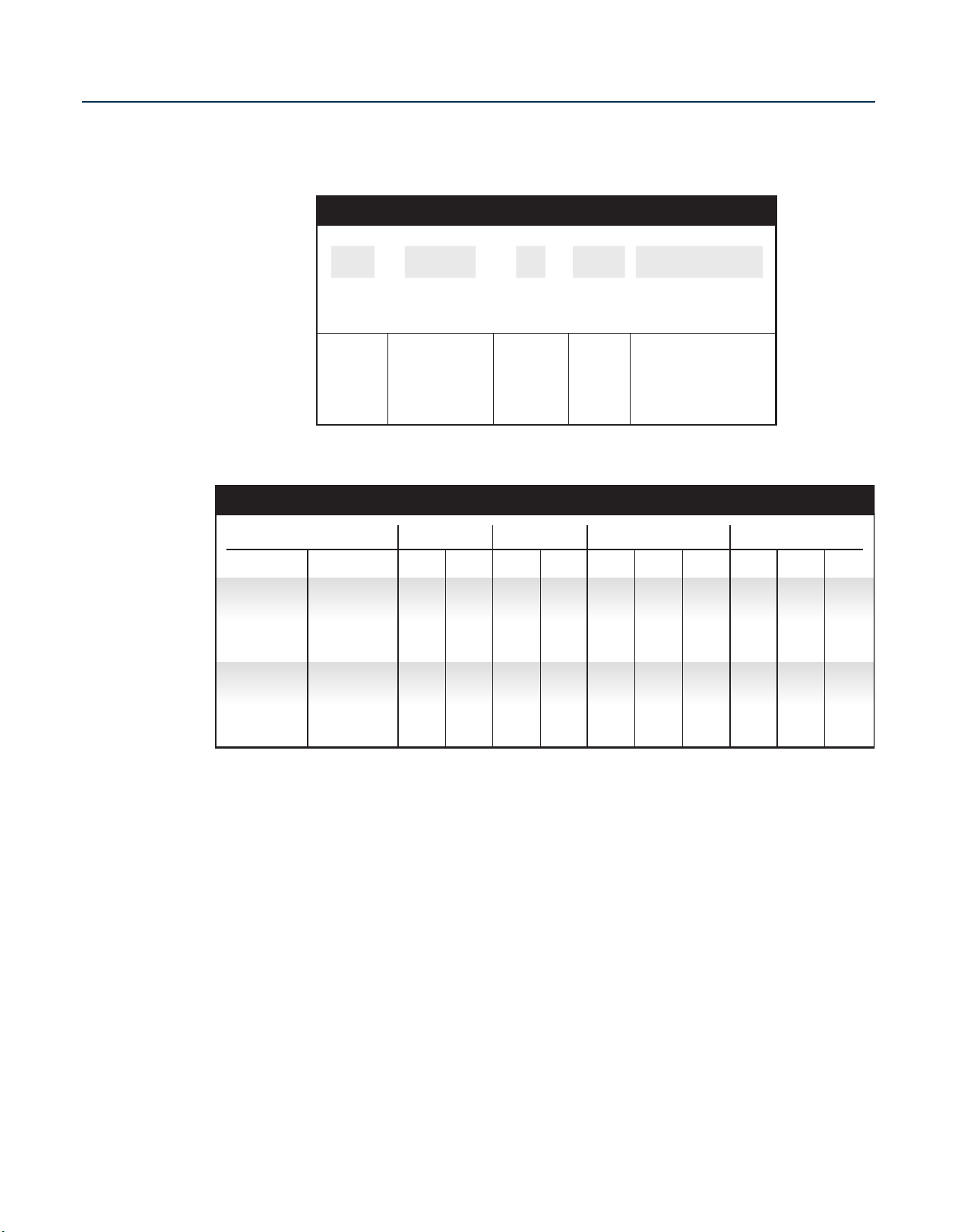
TECHNICAL
Dripper Flow
Dripper Interval
Lateral (Row) Spacings
Burial Depth
Application Rate (in./hr.)
Time to Apply 1/4"
of Water (in minutes)
Clay Soil
0.26 GPH
18"
18" - 22"
.19 - .15
79 - 100
Loam Soil
0.4 GPH
12"
18" - 22"
.43 - .35
35 - 43
Sandy Soil
0.6 GPH
12"
12" - 16"
.96 - .72
16 - 21
Clay Soil
0.26 GPH
18"
18" - 24"
.19 - .14
79 - 107
Sandy Soil
0.6 GPH
12"
16" - 20"
.72 - .58
21 - 26
Loam Soil
0.4 GPH
18"
18" - 24"
.29 - .21
52 - 71
SHRUB and GROUND COVERTURF
TECHLINE® CV General Guidelines
Maximum spacing recommendations: Following these spacing guidelines, dripper flow selection can be increased if desired by the designer.
On-surface or bury evenly throughout the zone to a maximum of 6 inches
109
325
409
469
0.4
86
256
322
369
0.6
127
427
539
618
0.26
65
194
244
280
0.9
151
459
579
664
0.4
91
274
346
397
0.9
152
458
580
666
0.6
116
348
440
506
0.9
15
25
35
45
Dripper Flow Rate (GPH)
INLET PRESSURE (psi)
120
361
456
523
0.6
177
604
763
877
0.26
TECHLINE CV DRIPPER SPACING
TECHLINE® CV Maximum Length of a Single Lateral (feet)
0.26 GPH Dripper 0.9 GPH Dripper
26.40 GPH
17.58 GPH
Not Available
0.44 GPM
0.29 GPM
Not Available
0.4 GPH Dripper
40.OO GPH
26.67 GPH
Not Available
0.67 GPM
0.44 GPM
Not Available
61.00 GPH
41.00 GPH
31.00 GPH
92.00 GPH
61.00 GPH
46.00 GPH
1.53 GPM
1.02 GPM
0.77 GPM
12"
18"
24"
0.6 GPH Dripper
1.02 GPM
0.68 GPM
0.51 GPM
TECHLINE® CV Flow (per 100 feet)
DRIPPER SPACING
DATA
TABLE 1
TABLE 2
TABLE 3
Page 29
28
N E T A F I M T E C H L I N E® C V D E S I G N G U I D E
N E T A F I M T E C H L I N E® C V D E S I G N G U I D E
TECHNICAL
DISC FILTER Recommended Filter Sizing
Filter Size
3
/4" 1" 1 1/2" 1 1/2" Super 2"
Filter Volume (cubic inches) 5.8 26.8 26.8 36.1 75
Filtration Area (square inches) 24.8 48.9 49 77.8 148
Mesh 40 80 120 140 200
Micron 400 200 130 115 75
Disc Color Blue Yellow Red Black Green*
Flow Rate (GPM) Friction Loss (psi)
4.4 0.40 0.14 – – –
8.8 1.46 0.54 – – –
13 3.40 1.34 – – –
17 – 2.10 – – –
22 – 3.24 1.10 1.10 –
26 – – 1.30 1.20 –
31 – – 1.70 1.20 –
35 – – 2.30 2.50 –
44 – – – 4.20 0.30
66 – – – – 0.63
88 – – – – 1.03
110 – – – – 1.47
132 – – – – 2.13
Losses shown are for a 140 mesh filtration element tested in potable water. The maximum recommended flow for each
filter is listed. Example: The maximum recommended flow for a 3/4" filter is 13 GPM. The maximum recommended
flow for a 1" filter is 22 GPM.
*Green not available for 3/4".
Disc Filter Sizing
DATA
Page 30
29
N E T A F I M T E C H L I N E® C V D E S I G N G U I D E
TECHNICAL
DATA
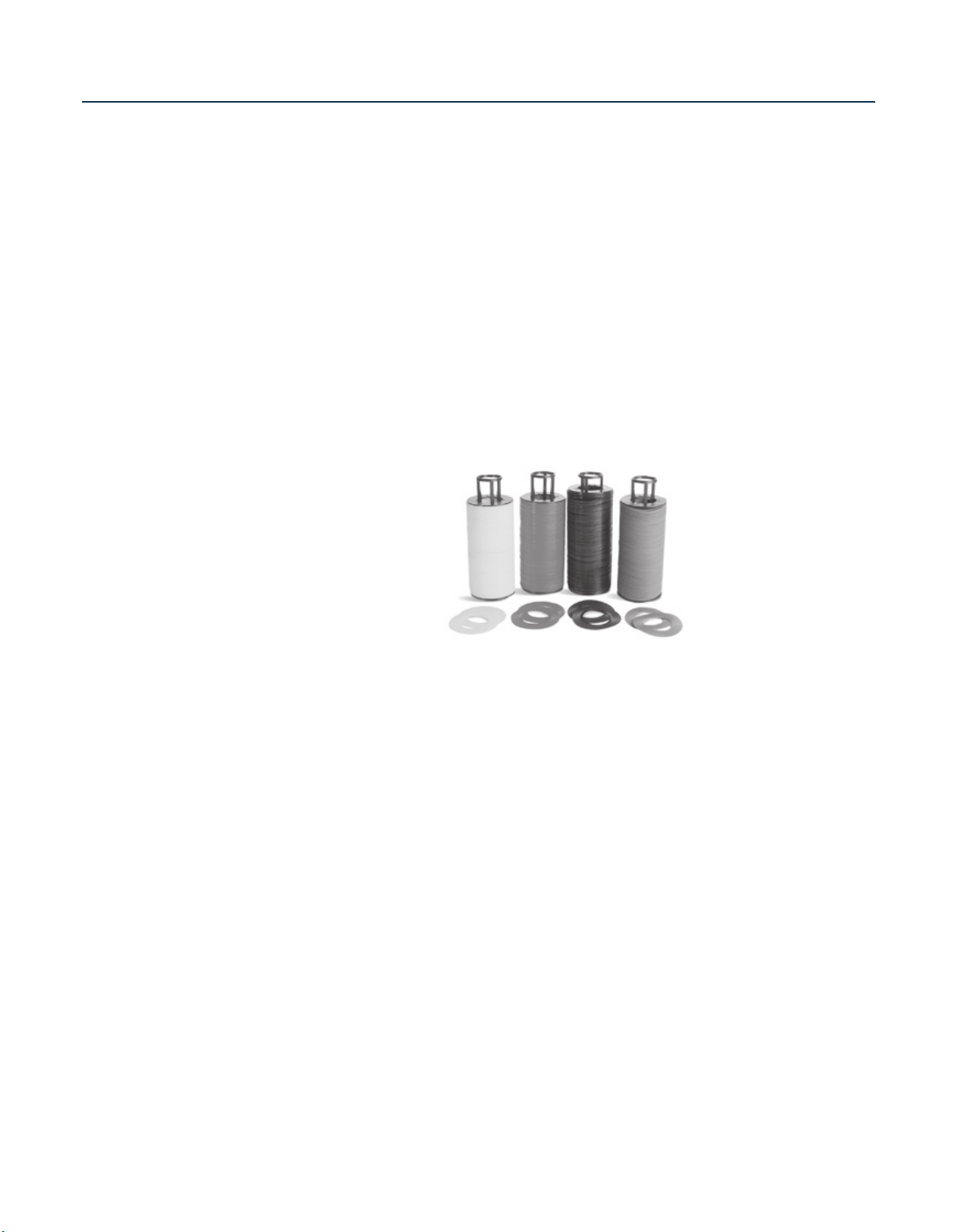
TECHLINE CV WITH TECHFILTER
Filters are an integral part of every drip system.
No system should be designed or assembled
without proper filtration. The primary function
is to filter out contaminants that could plug the
small orifices of the drippers. Netafimʼs Techfilter
serves a secondary purpose of protecting
against roots invading the system.
Triflurex® is incorporated into the replaceable
disk ring assemblies inside the filter housing.
When water passes through the filter, a very
low concentration of Trifluralin
level) is transmitted throughout the system.
The operation of this technology provides
very precise and even distribution of Trifluralin
through the piping network which will inhibit root
growth into the dripper outlets. No other uses
or claims are made for the use of this product
beyond the protection of the system from root
intrusion.
TECHFILTER INSTALLATION AND MOUNTING INSTRUCTIONS:
The installation of the Techfilter is no different than any other filter. It is advisable to install the filter so
the filter rings are easily removed for periodic cleaning of contaminants and replacement of the rings at
the end of their affectivity. The filter should be mounted so the cover can be easily disassembled and
the ring set, when removed, will not drop dirt or particle contaminants back into the filter body. Do not
install the filter in direct sunlight. The Techfilter should be mounted to avoid direct sunlight. Mounting in
an irrigation valve box, meter box or inside a building is preferred.
(parts per billion
®
EFFECTIVE USE AND REPLACEMENT GUIDELINES:
The Techfilter can effectively protect the system from root intrusion for 200 hours of use, but not longer
than 2 years of service. We recommend replacing the filter cartridge following the above guidelines.
®
is manufactured by Agan Chemical Manufacturers Ltd.
NOTE
Triflurex
Techfilter with Techline CV is sold together for use on a new installation as a part number as
shown on pages 31 - 33. Techfilter cannot be sold without the proper amount of Techline CV.
Page 31
30
N E T A F I M T E C H L I N E® C V D E S I G N G U I D E
N E T A F I M T E C H L I N E® C V D E S I G N G U I D E
Filter
Size
075 = 3/4"
10 = 1"
10L = 1" Long
15L = 1 1/2" Long
20 = 2"
Dripper
Flow
26 = 0.26 GPH
4 = 0.4 GPH
6 = 0.6 GPH
9 = 0.9 GPH
Dripper
Spacing
12 = 12"
18 = 18"
24 = 24"
Quantity
of Techline CV
Length of Techline CV
supplied with each
filter ordered.
See chart below.
Techfilter
TF XXX
XXXCVX
XX
TECHFILTER Specifying Information
TF
TECHLINE CV Minimum & Maximum Feet for Each Filter Size
0.4 GPH 0.6 GPH 0.9 GPH
Model Flow (GPM) 12" 18"
3
/4"
1"
1" Long or
1 1/2" Long
2"
Min. - 1
Max. - 7
Min. - 3
Max. - 22
Min. - 8
Max. - 40
Min. - 14
Max. - 90
448
3,284
1,194
5,970
2,089
13,433
682
5,000
1,818
9,090
2,181
20,454
294
2,157
784
3,922
1,373
8,824
441
3,235
1,176
5,882
2,059
13,235
588
4,314
1,569
7,843
2,745
17,647
196
1,438
523
2,614
915
5,882
294
2,157
784
3,922
1,373
8,824
390
2,857
1,039
5,195
1,818
11,688
149
1,044
227
1,590
12" 18"
98
686
147
1,029
24"
196
1,373
Use the flow rate of the zone or the number of feet of Techline CV to determine what size filter to use. Example: If you have a 7.37 GPM zone of .4/12"
Techline CV (7.37 GPM = 1,100' of dripperline) use the 1" Techfilter. Note: One or more Techfilter sizes may work for your application.
0.26 GPH
12" 18"
638
4,681
1,702
8,511
2,979
19,149
1,034
7,586
2,758
13,799
4,827
31,034
213
1,489
345
2,413
12" 18"
65
45898686
24"
130
909
TECHNICAL
DATA
Page 32

31
N E T A F I M T E C H L I N E® C V D E S I G N G U I D E
TECHFILTER with TECHLINE CV Model Number Descriptions
Filter Size Model Number
Description
1" TF10912-200CV 1" Techfilter w/200' .9 gph 12" Techline CV
1" TF10912-1000CV 1" Techfilter w/1,000' .9 gph 12" Techline CV
1" TF10918-300CV 1" Techfilter w/300' .9 gph 18" Techline CV
1" TF10918-1000CV 1" Techfilter w/1,000' .9 gph 18" Techline CV
1" TF10612-300CV 1" Techfilter w/300' .6 gph 12" Techline CV
1" TF10612-1000CV 1" Techfilter w/1,000' .6 gph 12" Techline CV
1" TF10618-350CV 1" Techfilterw/350' .6 gph 18" Techline CV
1" TF10618-1000CV 1" Techfilter w/1,000' .6 gph 18" Techline CV
1" TF10412-400CV 1" Techfilter w/400' .4 gph 12" Techline CV
1" TF10412-1000CV 1" Techfilter w/1,000' .4 gph 12" Techline CV
1" TF10418-600CV 1" Techfilter w/600' .4 gph 18" Techline CV
1" TF10418-1000CV 1" Techfilter w/1,000' .4 gph 18" Techline CV
1" TF102612-400CV 1" Techfilter w/400' .26 gph 12" Techline CV
1" TF102612-1000CV 1" Techfilterw/1,000' .26 gph 12" Techline CV
1" TF102618-600CV 1" Techfilter w/600' .26 gph 18" Techline CV
1" TF102618-1000CV 1" Techfilter w/1,000' .26 gph 18" Techline CV
3
/4" TF075912-100CV
3
/4" Techfilter w/100' .9 gph 12" Techline CV
3
/4" TF075912-1000CV
3
/4" Techfilter w/1,000' .9 gph 12" Techline CV
3
/4" TF075918-100CV
3
/4" Techfilter w/100' .9 gph 18" Techline CV
3
/4" TF075918-1000CV
3
/4" Techfilter w/1,000' .9 gph 18" Techline CV
3
/4" TF075612-100CV
3
/4" Techfilter w/100' .6 gph 12" Techline CV
3
/4" TF075612-1000CV
3
/4" Techfilter w/1,000' .6 gph 12" Techline CV
3
/4" TF075618-200CV
3
/4" Techfilter w/200' .6 gph 18" Techline CV
3
/4" TF075618-1000CV
3
/4" Techfilter w/1,000' .6 gph 18" Techline CV
3
/4" TF075412-100CV
3
/4" Techfilter w/100' .4 gph 12" Techline CV
3
/4" TF075412-1000CV
3
/4" Techfilter w/1,000' .4 gph 12" Techline CV
3
/4" TF075418-200CV
3
/4" Techfilter w/200' .4 gph 18" Techline CV
3
/4" TF075418-1000CV
3
/4" Techfilter w/1,000' .4 gph 18" Techline CV
3
/4" TF0752612-100CV
3
/4" Techfilter w/100' .26 gph 12" Techline CV
3
/4" TF0752612-1000C
3
/4" Techfilter w/1,000' .26 gph 12" Techline CV
3
/4" TF0752618-200CV
3
/4" Techfilter w/200' .26 gph 18" Techline CV
3
/4" TF0752618-1000C
3
/4" Techfilter w/1,000' .26 gph 18" Techline CV
TECHNICAL
DATA
Page 33

32
N E T A F I M T E C H L I N E® C V D E S I G N G U I D E
N E T A F I M T E C H L I N E® C V D E S I G N G U I D E
TECHNICAL
1" Long TF1OL912-500CV 1" Long Techfilter w/500' .9 gph 12" Techline CV
1" Long TF1OL912-1000CV 1" Long Techfilter w/1,000' .9 gph 12" Techline CV
1" Long TF1OL918-800CV 1" Long Techfilter w/800' .9 gph 18" Techline CV
1" Long TF1OL918-1000CV 1" Long Techfilter w/1,000' .9 gph 18" Techline CV
1" Long TF1OL612-800CV 1" Long Techfilter w/800' .6 gph 12" Techline CV
1" Long TF1OL612-1000CV 1" Long Techfilter w/1,000' .6 gph 12" Techline CV
1" Long TF1OL618-900CV 1" Long Techfilter w/900' .6 gph 18" Techline CV
1" Long TF10L618-1000CV 1" Long Techfilter w/1,000' .6 gph 18" Techline CV
1" Long TF1OL412-1100CV 1" Long Techfilter w/1,100' .4 gph 12" Techline CV
1" Long TF1OL412-1000CV 1" Long Techfilter w/1,000' .4 gph 12" Techline CV
1" Long TF10L418-1700CV 1" Long Techfilter w/1,700' .4 gph 18" Techline CV
1" Long TF10L418-1000CV 1" Long Techfilter w/1,000' .4 gph 18" Techline CV
1" Long TF10L2612-1000C 1" Long Techfilter w/1,000' .26 gph 12" Techline CV
1" Long TF10L2618-1000C 1" Long Techfilter w/1,000'.26 gph 18" Techline CV
1 1/2" Long TF15L912-500CV 1 1/2" Techfilter w/500' .9 gph 12" Techline CV
1 1/2" Long TF15L912-1000CV 1 1/2" Techfilter w/1,000' .9 gph 12" Techline CV
1 1/2" Long TF15L918-800CV 1 1/2" Techfilter w/800' .9 gph 18" Techline CV
1 1/2" Long TF15L918-1000CV 1 1/2" Techfilter w/1,000' .9 gph 18" Techline CV
1 1/2" Long TF15L612-800CV 1 1/2" Techfilter w/800' .6 gph 12" Techline CV
1 1/2" Long TF15L612-1000CV 1 1/2" Techfilter w/1,000' .6 gph 12" Techline CV
1 1/2" Long TF15L618-900CV 1 1/2" Techfilter w/900' .6 gph 18" Techline CV
1 1/2" Long TF15L618-1000CV 1 1/2" Techfilter w/1,000' .6 gph 18" Techline CV
1 1/2" Long TF15L412-1100CV 1 1/2" Techfilter w/1,100' .4 gph 12" Techline CV
1 1/2" Long TF15L412-1000CV 1 1/2" Techfilter w/1,000' .4 gph 12" Techline CV
1 1/2" Long TF15L418-1700CV 1 1/2" Techfilter w/1,700' .4 gph 18" Techline CV
1 1/2" Long TF15L418-1000CV 1 1/2" Techfilter w/1,000' .4 gph 18" Techline CV
1 1/2" Long TF15L2612-1000C 1 1/2" Techfilter w/1,000' .26 gph 12" Techline CV
1 1/2" Long TF15L2618-1000C 1 1/2" Techfilter w/1,000' .26 gph 18" Techline CV
TECHFILTER with TECHLINE CV Model Number Descriptions
Filter Size Model Number
Description
DATA
Page 34

33
N E T A F I M T E C H L I N E® C V D E S I G N G U I D E
TECHNICAL
TF075
3
/4" Techfilter Replacement Cartridge
TF100 1" Techfilter Replacement Cartridge
TF100L 1" Long and 1 1/2" Techfilter Replacement Cartridge
TF200 2" Techfilter Replacement Cartridge
2" TF20912-1000CV 2" Techfilter w/1,000' .9 gph 12" Techline CV
2" TF20918-1400CV 2" Techfilter w/1,400' .9 gph 18" Techline CV
2" TF20918-1000CV 2" Techfilter w/1,000' .9 gph 18" Techline CV
2" TF20612-1400CV 2" Techfilter w/1,400' .6 gph 12" Techline CV
2" TF20612-1000CV 2" Techfilter w/1,000' .6 gph 12" Techline CV
2" TF20618-1600CV 2" Techfilter w/1,600' .6 gph 18" Techline CV
2" TF20618-1000CV 2" Techfilter w/1,000' .6 gph 18" Techline CV
2" TF20412-2000CV 2" Techfilter w/2,000' .4 gph 12" Techline CV
2" TF20412-1000CV 2" Techfilter w/1,000' .4 gph 12" Techline CV
2" TF20418-3000CV 2" Techfilter w/3,000' .4 gph 18" Techline CV
2" TF20418-1000CV 2" Techfilter w/1,000' .4 gph 18" Techline CV
2" TF202612-2000CV 2" Techfilter w/2,000' .26 gph 12" Techline CV
2" TF202618-3000CV 2" Techfilter w/3,000' .26 gph 18" Techline CV
TECHFILTER with TECHLINE CV Model Number Descriptions
Filter Size Model Number
Description
DATA
Page 35

34
N E T A F I M T E C H L I N E® C V D E S I G N G U I D E
N E T A F I M T E C H L I N E® C V D E S I G N G U I D E
TECHNICAL
Remote Control Valve
with Disc Filter and PRV
Perimeter Laterals
(2" to 4" from edge)
PVC or Poly Supply Header
Techline CV Tubing Lateral
Area Perimeter
Manual Line Flushing Valve
Plumbed to PVC or Pol
y
PVC or Poly Exhaust Heade
r
LF
Techline Start Connection
Male Adapter
DATA
Techline CV End Feed Layout
Page 36

35
N E T A F I M T E C H L I N E® C V D E S I G N G U I D E
TECHNICAL
Manual Line Flushing Valve
Plumbed to PVC or Poly
Perimeter Laterals
(2" to 4" from edge)
Techline Start Connection
PVC or Poly Supply Header
Techline Start Connection
Male Adapter
Techline CV Tubing Lateral
Area Perimeter
PVC or Poly Exhaust Heade
r
LF
LF
Remote Control Valve
with Disc Filter and PRV
DATA
Techline CV Center Feed Layout
Page 37

36
N E T A F I M T E C H L I N E® C V D E S I G N G U I D E
N E T A F I M T E C H L I N E® C V D E S I G N G U I D E
INSTALLATION
CHECKLIST
Project:
Date:
1. Assemble and install remote control valve and pressure regulator as indicated in
Netafim detail(s) .
2. Assemble and install supply header as indicated in Netafim detail(s)
. Tape or plug all open connections.
3. Assemble and install exhaust header as indicated in Netafim detail(s)
. Tape or plug all open connections.
4. Install Techline CV laterals beginning at the start connection(s) indicated in Netafim
detail(s) . Type and layout of laterals are to be
installed as specified, and/or as indicated in Netafim detail(s) .
Tape or plug all open ends.
5. If required, install an air/vacuum relief valve at the point(s) of highest elevation in the
zone as indicated in Netafim detail(s) .
6. Make all Techline CV to fitting connections while flushing the system. Make
connections as indicated in Netafim detail(s) .
7. While flushing, connect Techline CV laterals to the exhaust header as indicated in
Netafim detail(s) .
8. Install line flushing valve(s) as indicated in Netafim detail(s) .
9. Install other Netafim accessories as indicated in Netafim detail(s) .
10. Operate and inspect the system. Record system data for historical record. Use
Netafim System Inspection Checklist.
Page 38

37
N E T A F I M T E C H L I N E® C V D E S I G N G U I D E
SYSTEM
INSPECTION
CHECK LIST
Techline CV Dripper Spacing 12” 18” 24”
Techline CV Lateral Spacing 12” 18” 24” Other "
Dripper Flow Rate 0.26 GPH 0.4 GPH 0.6 GPH 0.9 GPH
Type of Installation On-Surface Subsurface Depth below grade (inches)
Type of Pressure Regulator 3/4” Low Flow (0.25 to 4.4 GPM ) 3/4” High Flow (3.5 to 17.6 GPM )
1 1/2” Other
15 psi 25 psi 35 psi 45 psi
Disc Filter Size 3/4” 1” 1 1/2” 2”
Disc Filter Mesh 80 120 140 200
Project:
Date:
Operating Pressure psi
Pressure at Flush Valve psi
If More Than One Flush Valve psi psi psi
Controller Data
Station # Frequency x Per Week Run Time: Minutes Flow GPM
Station # Frequency x Per Week Run Time: Minutes Flow GPM
Station # Frequency x Per Week Run Time: Minutes Flow GPM
Station # Frequency x Per Week Run Time: Minutes Flow GPM
Station # Frequency x Per Week Run Time: Minutes Flow GPM
Station # Frequency x Per Week Run Time: Minutes Flow GPM
Station # Frequency x Per Week Run Time: Minutes Flow GPM
Station # Frequency x Per Week Run Time: Minutes Flow GPM
Page 39

38
N E T A F I M T E C H L I N E® C V D E S I G N G U I D E
N E T A F I M T E C H L I N E® C V D E S I G N G U I D E
Techline TELL
Elbow
Techline TLCOUP
Coupling
Techline TL075MA or TL050MA
Male Adapter
Techline TL075FTEE
2-Way Adapter Tee
Techline TLTEE
Tee
Techline TLCROSS
Cross
Techline TLW075MA
"V" 2-Way Adapter
Techline TLPLUG
Dripper Plug Ring
Techline TLFIG8
Line End
Techline TLTUBEADP
Micro-Tubing Adapter
3
/4" High Flow PRV
Pressure Regulating Valve
3
/4" Low Flow PRV
Pressure Regulating Valve
1 1/2" PRV
Pressure Regulating Valve
TLS6
6" Wire Staple
TLSOV
Shut-Off Valve (Barb x Barb)
DF-075
3/4" Disc Filter
TLAVRV
Air/Vacuum Relief Valve
TLIAPE
Insert Adapter for
1" or Larger
PE to Techline
TLIAPVC
Insert Adapter and
Grommet for 1 1/2" or Larger
PVC to Techline
TLCV
Inline Check Valve
FITTINGS
Page 40

39
N E T A F I M T E C H L I N E® C V D E S I G N G U I D E
MOST
Dripper Flow
Dripper Interval
Lateral (Row) Spacings
Burial Depth
Application Rate (in./hr.)
Time to Apply 1/4"
of Water (in minutes)
Clay Soil
0.26 GPH
18"
18" - 22"
.19 - .15
79 - 100
Loam Soil
0.4 GPH
12"
18" - 22"
.43 - .35
35 - 43
Sandy Soil
0.6 GPH
12"
12" - 16"
.96 - .72
16 - 21
Clay Soil
0.26 GPH
18"
18" - 24"
.19 - .14
79 - 107
Sandy Soil
0.6 GPH
12"
16" - 20"
.72 - .58
21 - 26
Loam Soil
0.4 GPH
18"
18" - 24"
.29 - .21
52 - 71
SHRUB and GROUND COVERTURF
TECHLINE® CV General Guidelines
Maximum spacing recommendations: Following these spacing guidelines, dripper flow selection can be increased if desired by the designer.
On-surface or bury evenly throughout the zone to a maximum of 6 inches
109
325
409
469
0.4
86
256
322
369
0.6
127
427
539
618
0.26
65
194
244
280
0.9
151
459
579
664
0.4
91
274
346
397
0.9
152
458
580
666
0.6
116
348
440
506
0.9
15
25
35
45
Dripper Flow Rate (GPH)
INLET PRESSURE (psi)
120
361
456
523
0.6
177
604
763
877
0.26
TECHLINE CV DRIPPER SPACING
TECHLINE® CV Maximum Length of a Single Lateral (feet)
0.26 GPH Dripper 0.9 GPH Dripper
26.40 GPH
17.58 GPH
Not Available
0.44 GPM
0.29 GPM
Not Available
0.4 GPH Dripper
40.OO GPH
26.67 GPH
Not Available
0.67 GPM
0.44 GPM
Not Available
61.00 GPH
41.00 GPH
31.00 GPH
92.00 GPH
61.00 GPH
46.00 GPH
1.53 GPM
1.02 GPM
0.77 GPM
12"
18"
24"
0.6 GPH Dripper
1.02 GPM
0.68 GPM
0.51 GPM
TECHLINE® CV Flow (per 100 feet)
DRIPPER SPACING
FREQUENTLY
USED CHARTS
TABLE 1
TABLE 2
TABLE 3
Page 41

N E T A F I M T E C H L I N E® C V D E S I G N G U I D E
NOTES
40
Page 42

NETAFIM USA
5470 E. Home Ave. • Fresno, CA 93727
888.638.2346 • 559.453.6800
FAX 800.695.4753
www.netafimusa.com
M-TCVDG 5/04
 Loading...