

Page 1
V 001.01 - MARCH 2018
USER MANUAL
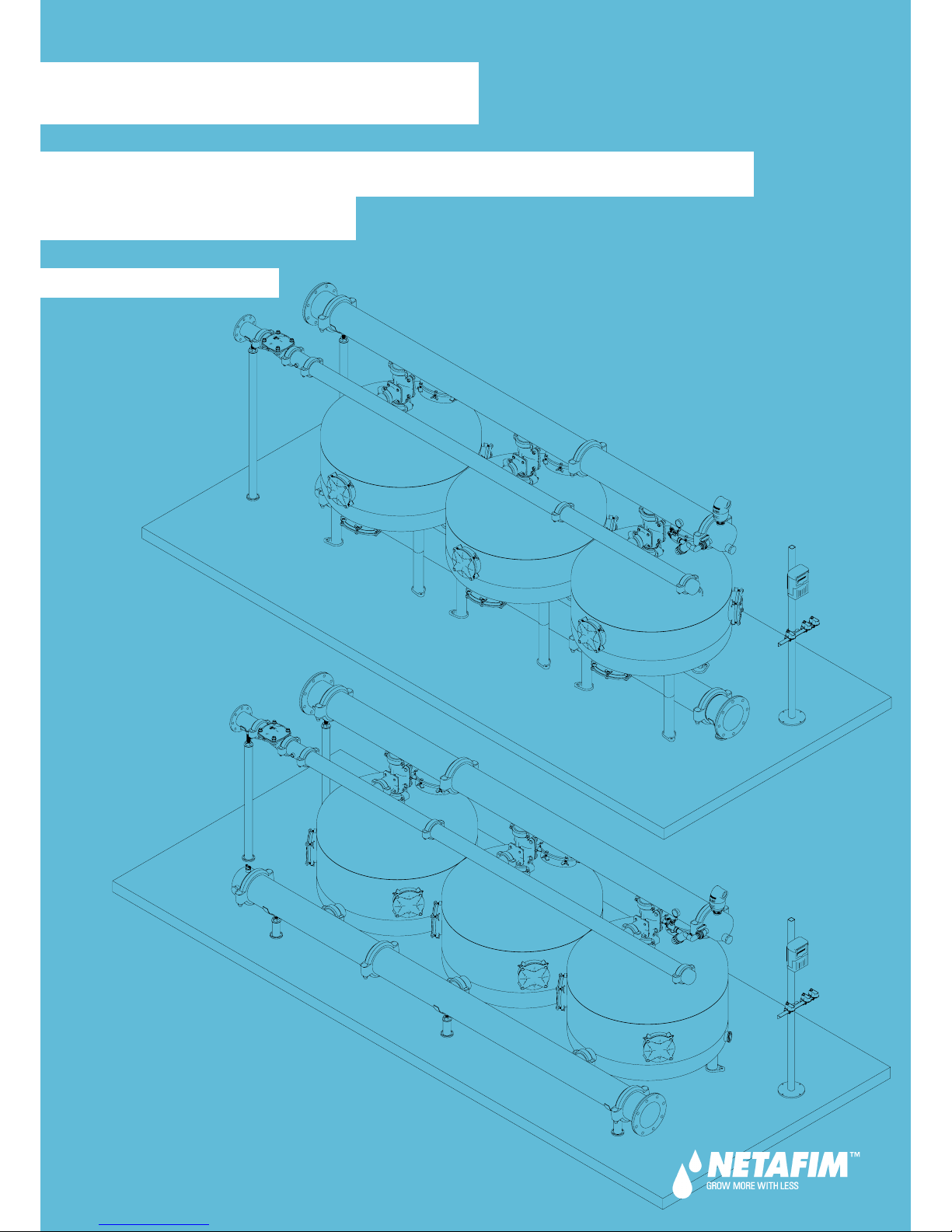
SANDSTORM
™
METAL SINGLE-/DOUBLE-CHAMBER
MEDIA FILTER
Page 2

© COPYRIGHT 2018, NETAFIM™
NO PARTS OF THIS PUBLICATION MAY BE REPRODUCED, STORED IN AN AUTOMATED DATA FILE OR MADE PUBLIC IN
ANY FORM OR BY ANY MEANS, WHETHER ELECTRONIC, MECHANICAL, BY PHOTOCOPYING, RECORDING OR IN ANY
OTHER MANNER WITHOUT PRIOR WRITTEN PERMISSION OF THE PUBLISHER.
ALTHOU GH NETA FIM™ TAKES THE GREATEST POSSIBLE CARE IN DESIGNING AND PRODUCING BOTH ITS PRODUCTS
AND THE ASSOCIATED DOCUMENTATION, THEY MAY STILL INCLUDE FAULTS.
NE TAFIM™ WILL NOT ACCEPT RESPONSIBILITY FOR DAMAGE RESULTING FROM THE USE OF NETAFIM'S PRODUCTS
OR THE USE OF THIS MANUAL.
NE TAFIM™ RESERVES THE RIGHT TO MAKE CHANGES AND IMPROVEMENTS TO ITS PRODUCTS AND/OR THE
ASSOCIATED DOCUMENTATION WITHOUT PRIOR NOTICE.
FOREIGN LANGUAGES
In the event that you are reading this manual in a language other than the English language, you
acknowledge and agree that the English language version shall prevail in case of inconsistency or
contradiction in interpretation or translation.
Page 3

CONTENTS
Introduction
Aim of this manual
Safety instructions
Tools required for maintenance and troubleshooting
Flange connection
Filtration system components and structure - single-chamber
Filtration system components and structure - double-chamber
Initial operation and adjustment
Maintenance
Once a week
Once every three months
At the end of the irrigation season
At the beginning of the next irrigation season
Algae and bacterial growth control
Replacing the media
Replacing the batteries in the BackFlush controller
Paint retouching of the tanks and manifolds
Cleaning the secondary filter
Troubleshooting
If the pressure difference across the filtration system is over 0.7 bar (10.15 PSI)
and the flushing cycle does not reduce it
If the flushing cycle does not start but the controller is initiating the flushing signal
and the solenoids are reacting (“clicking”)
If the media is running out through the backwash manifold during backwash
If media is running out through the outlet manifold during filtration
Replacement parts
Tanks - single-chamber
Tanks - double-chamber
Manifold sections
Manifolds accessories
Grooved couplings
Support legs
Control kit
Backwash 3-way hydraulic valve 2"
Backwash 3-way hydraulic valve 3"
Backwash 3-way hydraulic valve 4"
Backwash flow-control valve
BackFlush controller
DC actuator valve
Air Valve
Inlet adaptor pipe
Secondary filter
Warranty
4
4
5
5
6
7
8
10
10
11
12
13
14
15
16
16
18
18
18
19
20
22
24
25
25
26
27
28
30
32
34
35
35
35
36
36
37
Page 4
4 SANDSTORM™ SINGLE-/DOUBLE-CHAMBER USER MANUAL
Aim of this manual
The aim of this manual is to provide the user with general instructions for operation, maintenance and
troubleshooting of any configuration of the SandStorm™ metal single- or double-chamber media filtration
system.
All system components are shipped to the site packed in pallets and boxes with installation drawings, user
manual, and a packing list.
NOTE
This manual describes the operation, maintenance and troubleshooting processes of a generic
SandStorm™ filtration system and must be used in unison with the drawings supplied with the system.
Safety instructions
Before handling any part of the system, carefully read the instructions and act accordingly.
NOTE
The maximum working pressure of the filtration system is 8 bar (116 PSI). Make sure the pressure
at the inlet of the filtration system is not higher. (For filtration systems made to order, see the
maximum working pressure in the Product Order).
Check and make sure the pumps and valves do not exceed the tolerances of the system and match the
requirements of the system pressure and flow-rate specifications (see the documentation supplied with
the system).
WARNING
Do not perform maintenance operations or open filter ports before the pressure in the system is
fully released. For draining purposes, open any valve downstream from the filtration system until
the pressure is fully released. Check the pressure gauge to be sure it is at 0 before proceeding.
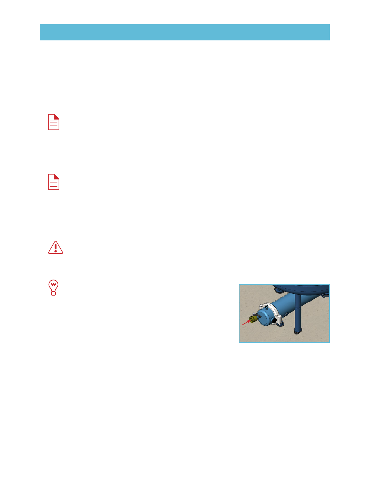
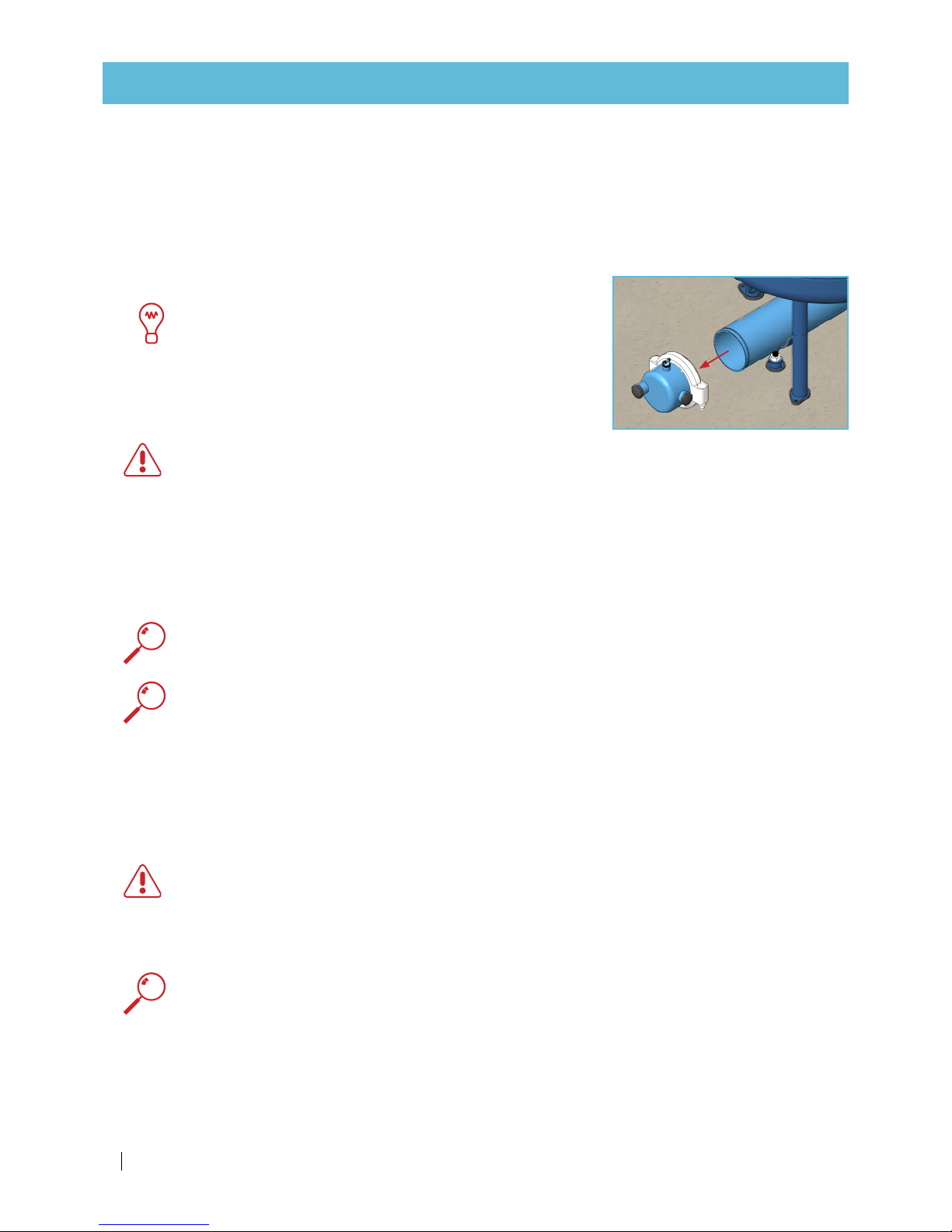
TIP
If a valve downstream from the filtration system is not available
for pressure release, you can install a manual valve on the lower
2" socket of the outlet manifold end-cap.
Electrical connections and wiring must be done by an authorized electrician only.
Be sure that prior to any maintenance procedures, all electrical connections to the system are unplugged
(AC controller, pumps, etc.).
Do not apply excessive force or pressure on the filtration system components.
Work only with proper and standard tools.
Use only original parts supplied/approved by Netafim™.
INTRODUCTION
Page 5
SANDSTORM™ SINGLE-/DOUBLE-CHAMBER USER MANUAL 5
INTRODUCTION
Handling sodium hypochlorite (NaClO) or hydrogen peroxide (H2O2)
WARNING
Sodium hypochlorite (NaClO) and hydrogen peroxide (H2O2) are dangerous toxic and corrosive
chemicals. All application regulations and safety rules must be observed. Store and handle them
according to safety regulations.
Before handling
sodium hypochlorite (NaClO)
or
hydrogen peroxide (H2O2)
, carefully read all the
specific safety, health protection and first aid information and instructions.
Be sure you have all
required first aid at the site, as instructed
.
Concentrated liquid sodium hypochlorite (NaClO) or hydrogen peroxide (H2O2) can damage exposed
metal (especially threads that are exposed to water). Be careful when applying them and avoid the
spillage of any of the liquid onto exposed metal parts. Should any of the liquid come into contact
with metal parts, immediately wash thoroughly with fresh water.
Tools required for maintenance and troubleshooting
• No special tools are needed. A standard toolkit is adequate.
• To connect grooved couplings: The following wrenches are required:
Grooved coupling size Bolt and nut size
(mm)
Wrench size
(mm)
inch mm
2 50 M10 17
3 80 M12 19
4 100 M12 19
6 150 M16 24
8 200 M20 30
10 250 M22 34
• To connect flanges: The following wrenches are required:
Flange size Bolt and nut size Wrench size
up to 8" 5/8" 15/16 "
10" to 14" 7/8" 1.1/ 8 "
Flange connection
In most cases, the filtration system manifolds are connected to the main line with flanges.
ATTENTION
When connecting flange pipe connectors, do not forget to place the rubber gasket in place.
Page 6
6 SANDSTORM™ SINGLE-/DOUBLE-CHAMBER USER MANUAL
INTRODUCTION
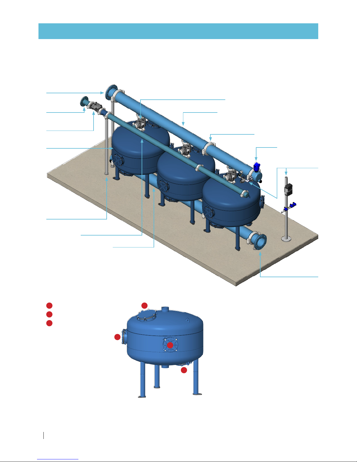
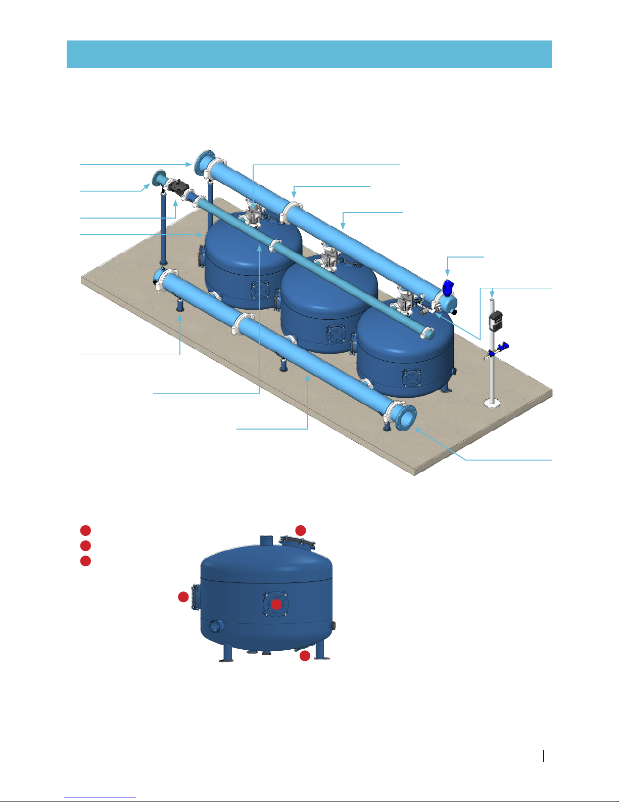
Filtration system components and structure
Single-chamber media filtration system
Media filter tank
Backwash 3-way hydraulic valves
Backwash
flow- control valve
Filtration system
control kit
Air valve
Inlet manifold
Outlet manifold
Backwash manifold
Grooved coupling
Manifold support legs
Inlet flange adaptor
Outlet
flange adaptor
Backwash
flange adaptor
Location of the tank ports
1
Filling port
2
Side service port
3
Bottom service port
1
2
2
3
Page 7
SANDSTORM™ SINGLE-/DOUBLE-CHAMBER USER MANUAL 7
INTRODUCTION
Media filter tank
Backwash 3-way hydraulic valves
Backwash
flow- control valve
Filtration system
control kit
Air valve
Inlet manifold
Outlet manifold
Backwash manifold
Grooved coupling
Manifold support legs
Inlet flange adaptor
Outlet
flange adaptor
Backwash
flange adaptor
Location of the tank ports
1
Filling port
2
Side service port
3
Bottom service port
1
2
2
3
Filtration system components and structure
Double-chamber media filtration system
Page 8
8 SANDSTORM™ SINGLE-/DOUBLE-CHAMBER USER MANUAL
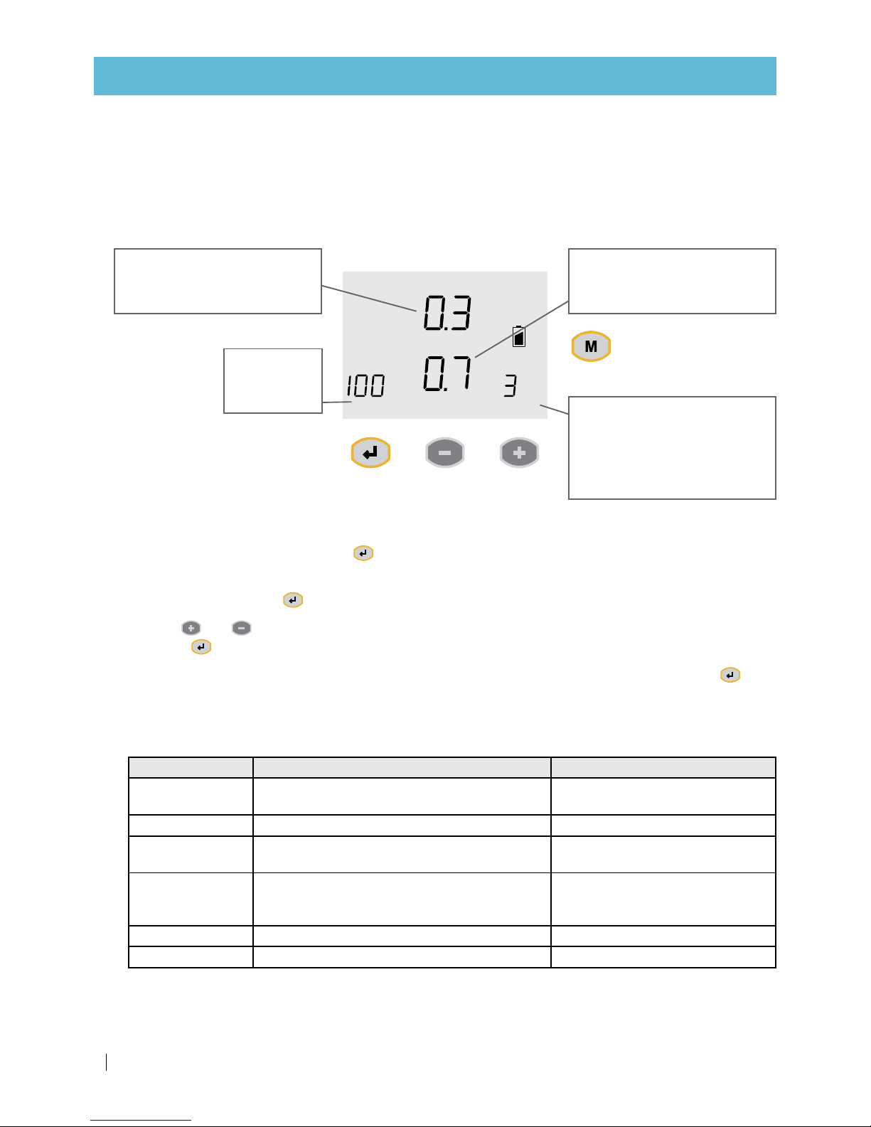
INITIAL OPERATION AND ADJUSTMENT
DP ACTUAL
DP SET
FLUSH
TIME
FLUSH
MODE
BARSec Hours
MANUAL
ENTER
The actual DP value.
Available only when the built-in
electronic DP sensor is used.
The DP set-point.
Available only when the built-in
electronic DP sensor is used.
The desired
flushing time
per station.
The desired flushing mode.
Contains either the flushing
interval or, when the flushing
is triggered by DP only, the
letters “DP.”
1.
Set the BackFlush controller:
The controller is equipped with an LCD display and 4 keys, as displayed below. When the unit is left
untouched for a minute, the display switches off and a beep is heard every 20 seconds to indicate it is
working.
Holding down any of the keys for a few seconds will bring the screen back to life.
The screen consists of several fields. Some of them are editable and some of them are not.
To enter the EDIT MODE, press the key. The EDIT MODE is indicated by blinking of the currently
editable field.
Each time you press the key, the next editable field becomes active and starts blinking.
Use the and keys to change the value in the active field.
Press the key again to set the selected value for the current field and move to the next editable field.
To return to a previous field during the process of passing through the editable fields, press the key
repeatedly until you get back to the FLUSH TIME field, and there are blinking fields. You can then begin
the process again.
Configuration
Parameter Definition Action
Main valve
(sustaining valve)
The pre-dwell delay between the main valve
opening and the opening of station 1
Select:
YES
if exists
Enter:
20 sec
Dwell time
The backwashing delay between stations Enter:
10 sec
DP delay
The delay during which the DP sensor reading
is expected to remain stable before reaction
Enter:
10 sec
Looping limit
The number of consecutive flushing cycles
triggered by the DP sensor before deciding
that there is an endless looping problem
Enter:
3
Alarm
Allocates one output for alarm activation Select:
YES
Delay valve
Allocates one output for delay-valve activation Select:
YES
if exists
(continued on the next page)
Page 9
SANDSTORM™ SINGLE-/DOUBLE-CHAMBER USER MANUAL 9
INITIAL OPERATION AND ADJUSTMENT
Parameter Definition Action
View outputs
This is a special mode that enables the user to
review the list of outputs and their allocations.
The output number is displayed in the bottom
left corner and its allocated function appears in
large letters in the center of the screen
Use the
key to toggle between
NO and YES and confirm by
pressing
the key
. Keep using
the key to review the list
Pressure units
Select the units to be used for pressure
measurement
Select:
BAR
or
PSI
Calibration
Zero calibration of the built-in electronic DP
sens or.
Disconnect the sensor ports from
the command tube and open them
to atmospheric pressure;
then select calibration:
YES
Version display
Displays the controller's software versionnumber.
No action required.
Press the key twice to
proceed.
Flush time
The desired flushing time per station. Enter:
100 sec
DP set-point
The pressure difference between the filter’s
inlet and outlet that initiates a flushing cycle.
Enter:
0.7 bar or 10 PSI
Flush mode
The flushing interval or, when the flushing is
triggered by DP only, the letters “DP.”
Enter:
3 hours
(For full instructions, see the BackFlush controller manual).
NOTE
If the filtration system was not ordered with a BackFlush controller and is used with an existing
irrigation system controller, see your irrigation controller user manual for instructions.
2.
Turn on the water and start irrigation.
3.
As soon as the system is pressurized and stable, start a manual backwashing cycle by pressing the
key. The icon will appear on the display (to manually terminate a backwashing cycle in progress,
press the same key).
4.
After completion of a full backwashing cycle, check that the filtration system DP is within the operational
range (0.15-0.4 bar/2.2-5.8 PSI, depending on the flow rate). Toggle the control kit 3-way ball valve and
note the filtration system inlet and outlet pressure. Subtract the outlet pressure from the inlet pressure.
The result is the filtration system DP.
5.
Check all the filtration system connections for water leaks – re-fit, re-connect and re-secure if necessary.
6.
Check all the command tube connections for leaks – re-fit, re-connect, and re-secure if necessary.
7.
Check that the backwashing cycle is performed in the correct order and that all the filters in the system
are backwashed in sequence.
8.
Check the secondary filter (if installed) for the presence of gravel.
NOTE
If a secondary filter is not installed, disconnect the main line pipe downstream from the filtration
system, let the water flow to the ground and visually check for the presence of gravel.
If gravel is present, see Troubleshooting, page 17.
ATTENTION
Steps 2 to 8 above should be performed whenever the operation of the filtration system is resumed
after being idle (i.e., after seasonal shutdown, maintenance or troubleshooting operations).
Configuration (continued)
Page 10
10 SANDSTORM™ SINGLE-/DOUBLE-CHAMBER USER MANUAL
MAINTENANCE
NOTE
It is highly recommended to keep track of the filtration system pressure regime. Make a dated list
of all maintenance activities with system pressure data.
Once a week
While the system is working:
1. Start a manual backwashing cycle by pressing the key (the icon will appear on the display) and
check that the backwashing happens in sequence according to your backwash controller setup (to
manually terminate a backwashing cycle in progress, press the same key).
2.
Check that during the last 10 seconds of the backwash of every filter, the water from the backwash
manifold runs out freely and clean.
3.
After completion of a full backwashing cycle, check that the filtration system DP is within the
operational range (0.15-0.4 bar/2.2-5.8 PSI, depending on the flow rate). Toggle the control assembly
3-way ball valve and note the filtration system inlet and outlet pressure. Subtract the outlet pressure
from the inlet pressure. The result is the filtration system DP.
4.
Check the control assembly filter and clean it (blockage of this filter will cause a malfunction of the
backwashing process).
5.
Check for leaks from connections and fittings - re-fit, re-connect and re-secure if necessary.
6.
Open the secondary screen filter (if installed) and check its condition - if necessary, take out the filtration
element and clean it with high pressure water. Put the filtration element back in place and close the
fil ter.
7.
Check the filtration system visually for any damage to the paint. If the protective coating of the tanks
and/or manifolds is damaged, see Paint retouching of the tanks and manifolds, page 16.
For further assistance, contact your local Netafim™ representative.
Once every three months
While the system is working:
1. Perform steps 1 - 5 as described in the weekly maintenance section above.
2.
Release the pressure from the filtration system. Open any valve downstream from the filtration system
or the manual valve (if installed) on the outlet manifold end-cap until the pressure is fully released.
Check the pressure gauge to be sure it is at 0 before proceeding.
3.
Empty all the water from the filtration system. Open any valve downstream from the filtration system or
the manual valve (if installed) on the outlet manifold end-cap.
4.
Open the filling port (top port) of all the tanks.
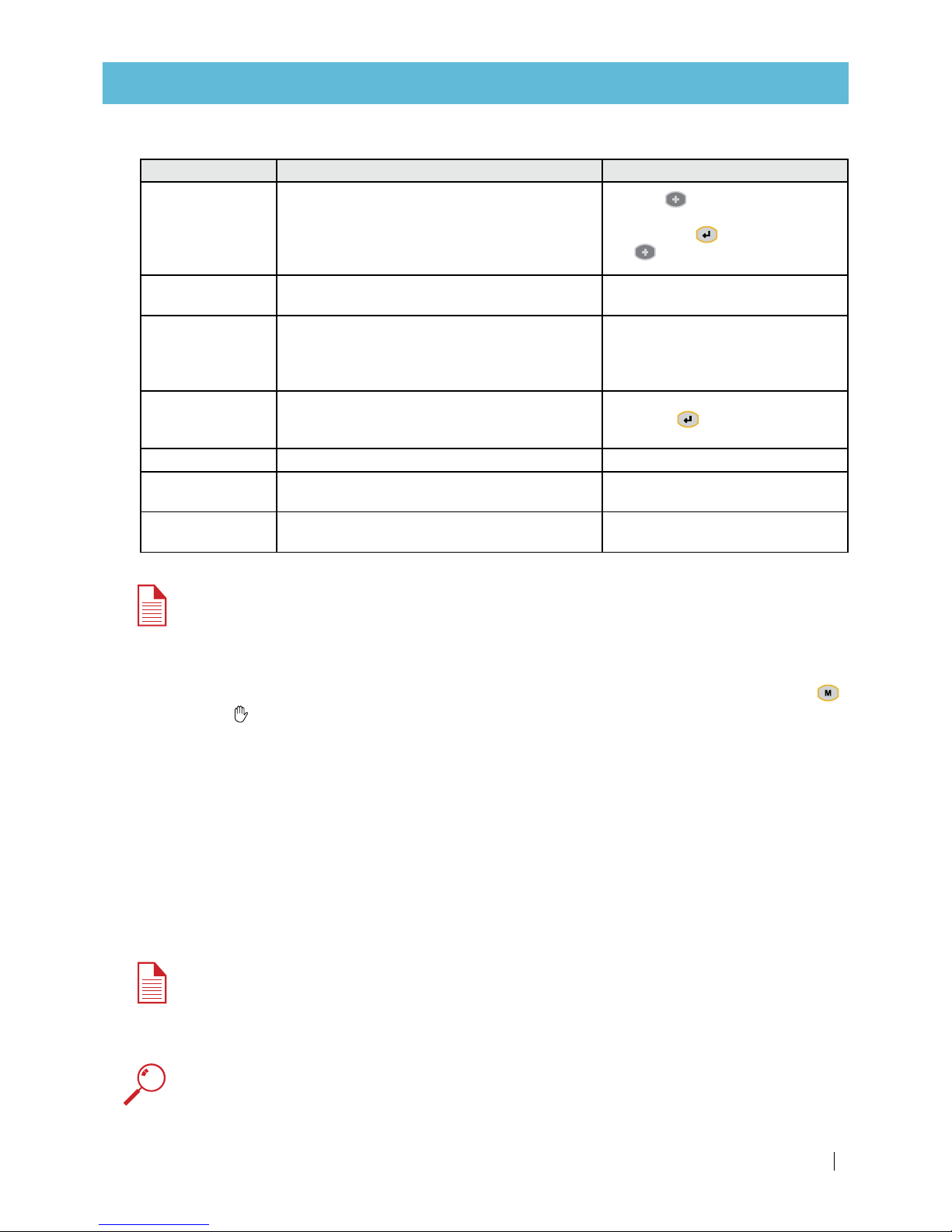
TIP
To speed up emptying the water from the filtration system,
you can temporarily dismantle the outlet manifold end-cap.
Page 11

SANDSTORM™ SINGLE-/DOUBLE-CHAMBER USER MANUAL 11
MAINTENANCE
5.
Visually check the filtration system (externally and inside the tanks, with the aid of a flashlight) for
any damage to the paint. If the protective coating of the tanks and/or manifolds is damaged, see Paint
retouching of the tanks and manifolds, page 16.
6.
Check the level of media inside the filters.
• If the level is lower than the media level marker on the filter tank - add media.
• If the level is higher than the media level marker on the filter tank - remove media.
7.
Manually stir the media inside the tank and check for media solidification.
• If the media has solidified, crumble it with high pressure water.
WARNING
Do not use tools (such as a shovel) to crumble the media, as this could damage the elements inside
the tank.
8.
Open the secondary screen filter (if installed) and check its condition - if necessary, remove the filtration
element and clean it with high pressure water. Put the filtration element back in place and close the
fil ter.
For further assistance, contact your local Netafim™ representative.
At the end of the irrigation season
ATTENTION
Never leave the filtration system unclean for the winter season.
1.
During the last irrigation cycle of the season: Check the filtration system inlet and outlet pressure and
make sure that they and the DP (Delta pressure) fit the system benchmark data.
2.
Perform all actions as described in the weekly maintenance section, page 10.
3.
Check that the backwashing parameters in the controller are correct. If not, enter the correct data.
4.
Close the water inlet to the filtration system.
5.
Perform steps 2 - 4 as described in the quarterly maintenance section, page 10.
6.
Check the level of media inside the filters.
• If the level is lower than the media level marker on the filter tank - add media.
• If the level is higher than the media level marker on the filter tank - remove media.
7.
Open the secondary screen filter (if installed) and check for gravel. If there is gravel, empty the tank that
is losing media and replace the damaged under-drain diffuser/s ("flute/s" or "mushroom/s")
(see Replacing a damaged under-drain diffuser part, page 18).
8.
Perform chemical cleaning of the media (see Algae and bacterial growth control, page 13).
9.
Turn off the water.
10.
Open the secondary screen filter (if installed), remove the screen, clean it and store it in a dry and safe
place with all the filter covers and handles.
• For manual filters: Make sure that the cover gaskets are dry before storage.
• For automatic or semi-automatic filters: Open the filter and check all the inner elements.
11.
Lubricate all the screws and bolts of the system. In particular, carefully oil the screws of the shutter
units in the gravel filter and the secondary screen filter (if it is a manual filter).
Page 12

12 SANDSTORM™ SINGLE-/DOUBLE-CHAMBER USER MANUAL
MAINTENANCE
12.
Open all gravel-filter covers, drain all the water out of the filtration system (preferably by removing the
outlet manifold end-cap). When the filters are completely drained, close the filling ports.
13.
Disconnect the electricity source of the backwash controller (for battery-operated controllers – remove
the batteries).
For further assistance, contact your local Netafim™ representative.
At the beginning of the next irrigation season
1.
Check all covers, gaskets and screen/s that were stored at the end of the previous season. Clean them
and wash with fresh water.
2.
Check the level of media inside the filters.
• If the level is lower than the media level marker on the filter tank - add media.
• If the level is higher than the media level marker on the filter tank - remove media.
3.
Install the screen and cover of the secondary screen filter.
4.
Connect the electricity source to the controller (for battery-operated controllers – replace the old
batteries with new ones) and perform a manual backwash – be sure that the controller sends signals in
sequence to the solenoids valves and that the solenoids are reacting.
5.
Clean the screen filter in the control assembly with fresh water.
6.
Lubricate all the screws and bolts of the system. In particular, carefully oil the screws of the port covers
in the gravel filter and the secondary screen filter cover.
7.
Perform chemical cleaning of the media (see Algae and bacterial growth control, page 13).
8.
Run according to the irrigation program.
For further assistance, contact your local Netafim™ representative.
Page 13

SANDSTORM™ SINGLE-/DOUBLE-CHAMBER USER MANUAL 13
MAINTENANCE
Algae and bacterial growth control
WARNING
Sodium hypochlorite (NaClO) and hydrogen peroxide (H2O2) are dangerous toxic and corrosive
chemicals. All application regulations and safety rules must be observed. Store and handle them
according to safety regulations.
Before handling
sodium hypochlorite (NaClO)
or
hydrogen peroxide (H2O2)
, carefully read all the
specific safety, health protection and first aid information and instructions.
Be sure you have all
required first aid at the site, as instructed
.
Concentrated liquid sodium hypochlorite (NaClO) or hydrogen peroxide (H2O2) can damage exposed
metal (especially threads that are exposed to water). Be careful when applying them and avoid the
spillage of any of the liquid onto exposed metal parts. Should any of the liquid come into contact
with metal parts, immediately wash thoroughly with fresh water.
1.
Perform 1 or 2 manual backwashes of the system (as needed), using the manual option in the controller.
2.
Release the pressure from the filtration system. Open any valve downstream from the filtration system
or the manual valve (if installed) on the outlet manifold end-cap, until the pressure is fully released.
Check the pressure gauge to be sure it is at 0 before proceeding. Do not drain the system.
3.
Open the top service ports of all the tanks.
4.
Make sure that the tanks remain two-thirds full with water. This is essential for the success of the
chemical treatment.
5.
Pour the required quantity of sodium hypochlorite (NaClO) or hydrogen peroxide (H2O2) into each tank
according to the table below.
Tank
diameter
(inch)
Quantity of sodium hypochlorite (NaClO) (liter) Quantity of hydrogen peroxide (H
2O2
) (liter)
Domestic liquid
3% concentration
Technical liquid
10% concentration
Technical liquid
30% concentration
12 0.7 0.25 0.15
16 0.8 0.3 0.15
20 1.1 0.4 0.2
24 1.5 0.5 0.2
30 3.0 1.0 0.3
36 5.0 1.5 0.5
48 10.0 3.0 1.5
6.
Gently stir the media inside each tank with a wooden stick.
WARNING
Take care not to damage the tank under-drain diffuser/s ("flutes" or "mushrooms").
7.
Wait at least 3 hours for the chemical contact time.
8.
Close the top service ports of all the tanks.
9.
Pressurize the system.
10.
Perform 1 or 2 manual backwashes of the system (as needed), using the manual option in the controller.
For further assistance, contact your local Netafim™ representative.
Page 14

14 SANDSTORM™ SINGLE-/DOUBLE-CHAMBER USER MANUAL
MAINTENANCE
Replacing the media
WARNING
Do not perform maintenance operations or open filter ports before the pressure in the system is
fully released. For draining purposes, open any valve downstream from the filtration system until
the pressure is fully released. Check the pressure gauge to be sure it is at 0 before proceeding.
The sand media usually requires replacement every 3 to 5 years, depending on water quality and how
much the system operates.
1.
Close all the valves, open the top and bottom service ports of all the tanks and remove their covers.
2.
Drain and flush all the media from the tank.
CAUTION
Do not use tools to help remove the media - under-drain diffusers ("flutes" or "mushrooms") could
be damaged.
TIP
If the sand media is solidified inside the tank and does not pour out of the bottom service port by
itself, you can crumble it with pressurized water through the bottom service port.
3.
Rinse and clean the inside of the tank.
4.
Visually check (with the aid of a flashlight) the inside of all the tanks, through the filling port, for
damaged, missing or unsecured under-drain diffusers ("flutes" or "mushrooms"). Replace, re-fit, re-
connect and re-secure if necessary (See tank replacement parts: single-chamber - page 20, double-
chamber - page 22).
5.
Make sure that the bottom service port and its gasket are clear of any remaining gravel particles and
close the bottom service port.
ATTENTION
Single-chamber only
Before filling the tanks with media, Fill each tank with water up to a third of its height with a hose
through the filling port before media filling to prevent damage to the under-drain diffusers when
pouring the media.
6.
Fill the tanks with media through the filling port. Fill each tank up to the media level marker on the filter tank.
*Crushed basalt.
Tank diameter
(inch)
Sand quantity*
kg lbs
12 60 132
16 90 198
20 120 265
24 180 397
30 240 529
36 360 794
48 575 1768
Tank diameter
(inch)
Sand quantity*
kg lbs
30 270 595
36 350 770
48 675 1490
Single-chamber Double-chamber
7.
Flatten the surface of the media.
Page 15
SANDSTORM™ SINGLE-/DOUBLE-CHAMBER USER MANUAL 15
MAINTENANCE
8. Make sure that the filling port and its gasket are clear of any remaining gravel particles and clos the
filling port.
9.
Turn on the water and start irrigation.
10.
As soon as the system is pressurized and stable, start a manual backwashing cycle by pressing the
key (the icon will appear on the display) and check that the backwashing happens in sequence
according to your backwash controller setup (to manually terminate a backwashing cycle in progress,
press the same key).
11.
Readjust the backwash flow-control valve:
• If a manual backwash flow-control valve is installed, throttle the valve to reduce the flow until the
media stops running out.
• If a hydraulic backwash flow-control valve is installed, the valve is factory pre-set to the required
flow rate.
In the rare case that the backwash flow-control valve requires fine-tuning:
a.
Release the pilot lock-nut.
b.
Gently rotate the pilot calibration bolt counterclockwise with a wrench to reduce the flow until the
media stops running out.
c.
Retighten the pilot lock-nut.
For further assistance, contact your local Netafim™ representative.
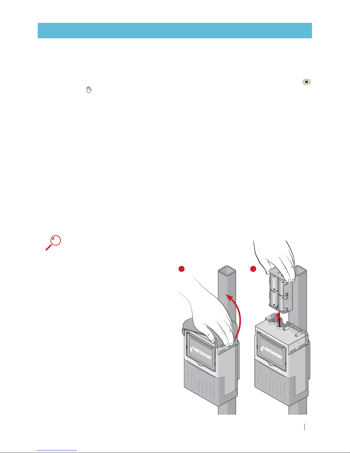
Replacing the batteries in the BackFlush controller
For controllers powered by 4 x 1.5v D-size batteries (6v DC)
ATTENTION
• Match the poles to the markings inside the battery housing.
• Always replace the whole set of 4 batteries at once.
1.
Remove the upper cover.
2.
Pull out the battery housing
.
3.
Remove the used batteries from the battery
housing
.
4.
Insert new batteries.
5.
Push the battery housing back in.
6.
Put the upper cover back in place.
1 2
Page 16

16 SANDSTORM™ SINGLE-/DOUBLE-CHAMBER USER MANUAL
MAINTENANCE
Paint retouching of the tanks and manifolds
WARNING
If the protective coating (inside and outside) of the tanks and manifolds is damaged and the bare
metal is exposed, it will rust in contact with irrigation water and chemicals. If neglected, this will
lead to a leak.
A tin of polyester protective repair paint (color: RAL 5010) is supplied with the system.
Any damage to the protective coating of the tanks and manifolds must be repaired as soon as possible.
1.
Sand the damaged area or spot with sandpaper and clean it with a wire brush.
2.
Apply the protective paint.
3.
Let the paint completely dry for at least 24 hours before exposing the mended spot to water.
For further assistance, contact your local Netafim™ representative.
Cleaning the secondary filter
At the end of the irrigation season and during the irrigation season, at the frequency required by the
irrigation water quality.
Remove the filtration element from the filter casing and clean it according to the instructions in the filter
user manual.
Page 17

SANDSTORM™ SINGLE-/DOUBLE-CHAMBER USER MANUAL 17
TROUBLESHOOTING
WARNING
Do not perform maintenance operations or open filter ports before the pressure in the system is
fully released. For draining purposes, open any valve downstream from the filtration system until
the pressure is fully released. Check the pressure gauge to be sure it is at 0 before proceeding.
Alternatively, you can open the valve installed on the outlet manifold end-cap - if installed.
If the pressure difference across the filtration system is over 0.7 bar (10.15 PSI) and the
flushing cycle does not reduce it:
1.
Check the system flow rate to see if the flow rate corresponds with the benchmark data, to make sure
that the system flow rate is not too high.
2.
If the pressure differential is not caused by a high flow rate, perform the following steps.
3.
Adjust the flow-control valve if necessary.
4.
Make sure that the water from the backwash manifold is running free.
5.
Check the duration of backwash and make sure the water that drains in the last 10 seconds of flushing
is clean.
If the water is dirty at the end of the flushing – increase the duration of flushing – if required, increase
the backwash duration and perform 3 consecutive flushing cycles.
If the flushing cycle does not start but the controller is initiating the flushing signal and
the solenoids are reacting (“clicking”):
1.
Check the command filter in the control head. Clean it if necessary and perform manual flushing.
2.
Check for clogging inside the solenoid valves - clean if possible or replace with a new solenoid.
3.
Check for clogging of the hydraulic control tubes - open the clogs and clean if necessary.
4.
Check for a ruptured or defective hydraulic control tube - replace if necessary.
If the media is running out through the backwash manifold during backwash:
1.
Adjust the backwash flow-control valve on the backwash manifold.
• If a manual backwash flow-control valve is installed, throttle the valve to reduce the flow until the
media stops running out.
• If a hydraulic backwash flow-control valve is installed, the valve is factory pre-set to the required
flow rate.
In the rare case that the backwash flow-control valve requires fine-tuning:
a.
Release the pilot lock-nut.
b.
Gently rotate the pilot calibration bolt counterclockwise with a wrench to reduce the flow until the
media stops running out.
c.
Retighten the pilot lock-nut.
2.
Check the level of media inside the filters.
• If the level is lower than the media level marker on the filter tank - add media.
• If the level is higher than the media level marker on the filter tank - remove media.
Page 18
18 SANDSTORM™ SINGLE-/DOUBLE-CHAMBER USER MANUAL
TROUBLESHOOTING
If media is running out through the outlet manifold during filtration:
Replacing a damaged under-drain diffuser part ("flute" or "mushroom"):
1.
Release the pressure and drain the filtration system. Open any valve downstream from the filtration
system or the manual valve (if installed) on the outlet manifold end-cap, until the pressure is fully
released. Check the pressure gauge to make sure it is at 0 before proceeding.
2.
Empty the water from the filtration system.
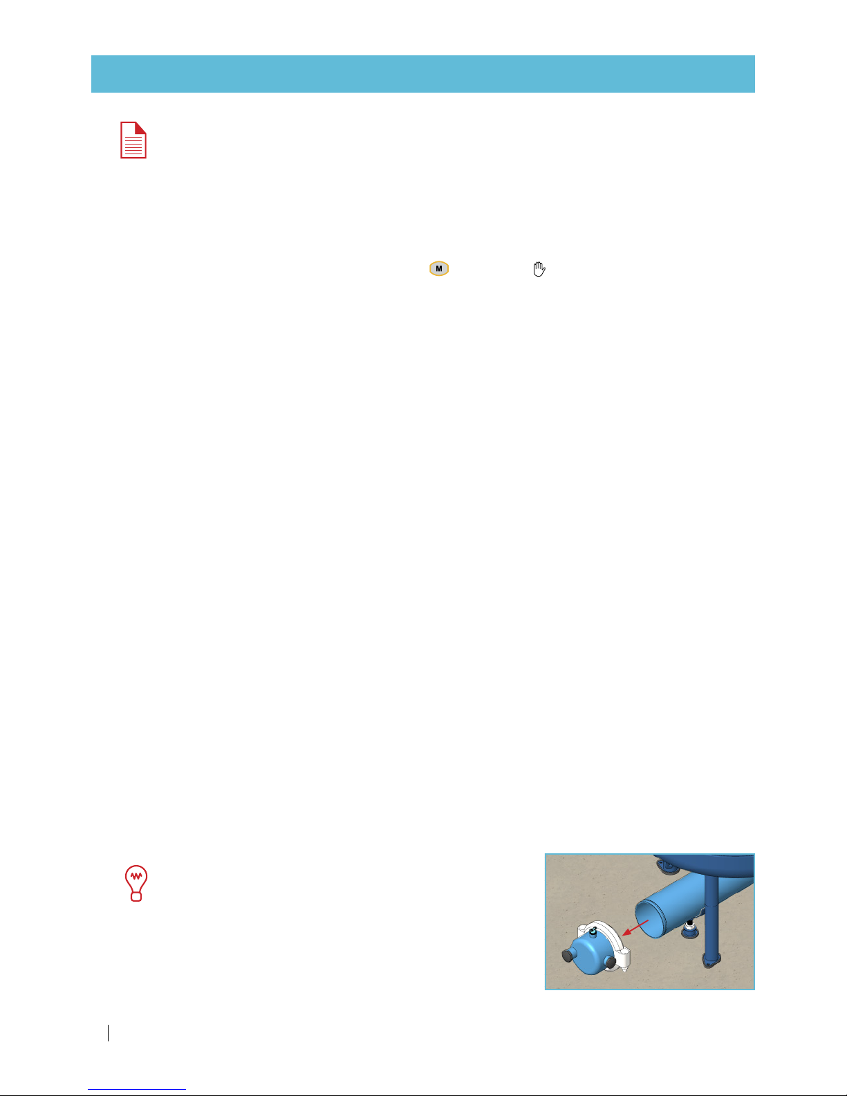
TIP
To speed up emptying the water from the filtration system,
you can temporarily dismantle the outlet manifold end-cap.
3.
Open the top service ports of all the tanks.
4.
Gently remove the media from all the tanks.
WARNING
Do not use tools (such as a shovel) to remove the media, as this could damage the tank under-drain
diffusers ("flutes" or "mushrooms").
5.
Clean any media remaining on the under-drain diffuser with pressurized water (with a hose, through the
top service ports).
6.
Visually identify the damaged under-drain diffuser part/s ("flute/s" or "mushroom/s") with the aid of a
flashlight.
ATTENTION
There may be more than one tank losing gravel.
ATTENTION
Screw, unscrew and fasten the under-drain diffuser parts by hand only. Do not use tools, as this
could damage the under-drain diffusers ("flutes" or "mushrooms").
7.
Manually unscrew the damaged under-drain diffuser part.
8.
Check the integrity of the following parts and replace them it if necessary:
• Single-chamber tank - the plastic washer (yellow).
• Double-chamber tank - the rubber gasket.
WARNING
A damaged rubber gasket may be difficult to pull out. Do not use a screwdriver (or any metal tool)
to remove it, as this could damage the tank protective coating.
9.
Replace the damaged under-drain diffuser part ("flute" or "mushroom") with a new one.
ATTENTION
Do not forget to put the following parts back in place:
• Single-chamber tank - the plastic washer (yellow).
• Double-chamber tank - the rubber gasket.
Page 19

SANDSTORM™ SINGLE-/DOUBLE-CHAMBER USER MANUAL 19
TROUBLESHOOTING
ATTENTION
Single-chamber only
Before filling the tanks with media, fill each tank with water up to a third of its height with a hose
through the filling port before media filling.
10.
Fill the tanks with media through the filling port. Fill each tank up to the media level marker on the filter tank.
*Crushed basalt.
Tank diameter
(inch)
Sand quantity*
kg lbs
12 60 132
16 90 198
20 120 265
24 180 397
30 240 529
36 360 794
48 575 1768
Tank diameter
(inch)
Sand quantity*
kg lbs
30 270 595
36 350 770
48 675 1490
Single-chamber Double-chamber
11.
Flatten the surface of the media.
12.
Make sure that the filling port and its gasket are clear of any remaining gravel particles and close the
filling port.
13.
Turn on the water and start irrigation.
(See tank replacement parts: single-chamber - page 20, double-chamber - page 22).
For further assistance, contact your local Netafim™ representative.
Page 20
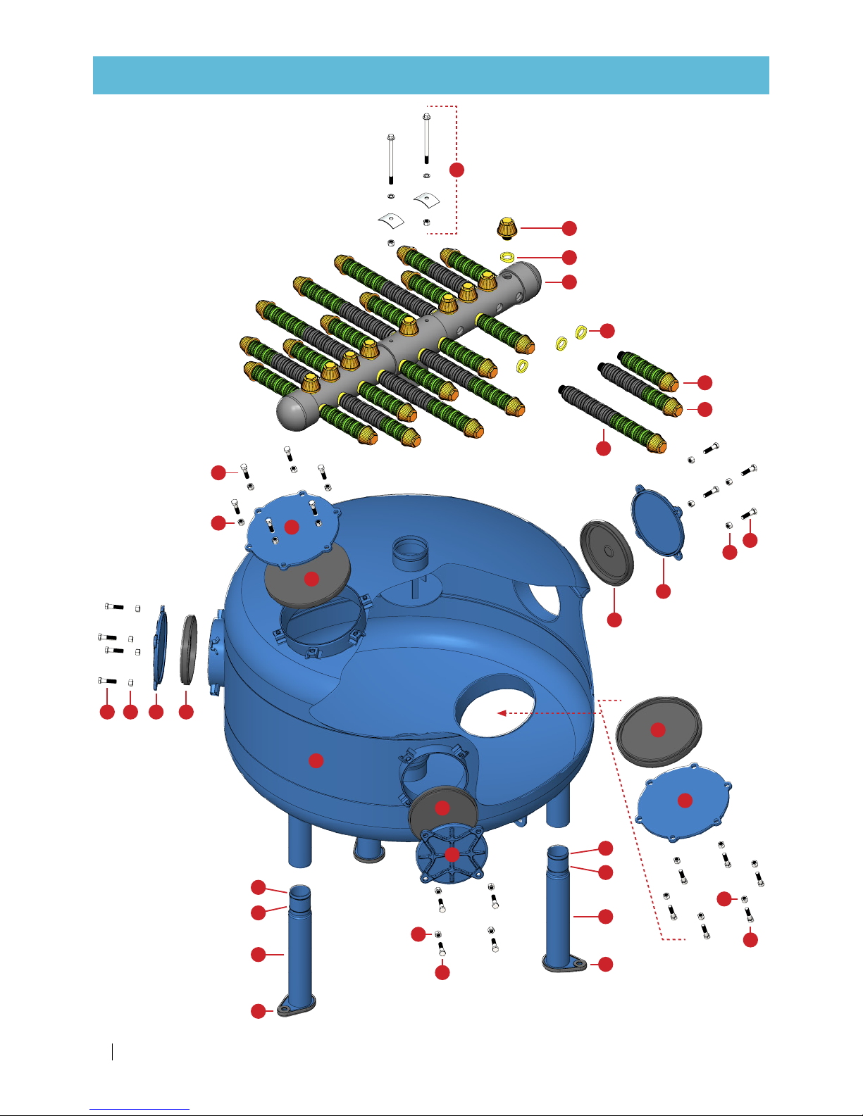
20 SANDSTORM™ SINGLE-/DOUBLE-CHAMBER USER MANUAL
ITEM
NO.
1
48'' UNDER CAMBER SINGLE
2
48'' BODY SHEET SINGLE
3
48'' TOP CAMBER SINGLE
4
10'' COVER GASKET
5
6
hex bolt gradeab_iso(ISO 4014 -
7
hex nut gradec_iso(Hexagon
Nut ISO - 4034 - M12 - S)
8
8'' COVER GASKET
9
8'' CAST IRON COVER
10
11
PVC pipe PN25-48''
12
underdrain bolt M12
13
spring washer M12
14
REPLACEMENT PARTS
Tanks 30, 36, 48"
Tanks - single-chamber
REV.
DESCRIPTION
Drawing No.
Project:
Permissible deviations in mm for ranges in nominal lengths
3-D Proj.
Part No.
Scale:
Sheet Size:
A3
Subject:
Part Name:
Material:
1:50
Finish:
/1
Quantity:
±0.05
≥ 0.5
≤ 3
> 3
≤ 6
±0.05
1
3
4
3
5
6
11
12
13141211
11
12
14
13
9
10
15
15
16
17
14
13
10
9
15
15
16
17
2
12
11
12
11
7
8
Page 21

SANDSTORM™ SINGLE-/DOUBLE-CHAMBER USER MANUAL 21
REPLACEMENT PARTS
Part Description Tank diameter (in) Cat. No.
1 Filter body Not available as spare part
2 Undedrain collector
30 71915-000124
36 71915-000125
48 71915-000126
3 Plastic washer All 71915-000128
4 Mushroom diffuser All 71915-000127
5 Underdrain element - S All 71915-000131
6 Underdrain element - M 36, 48 71915-000132
7 Underdrain element - L 48 71915-000133
8 Underdrain screw set (2X) All 71915- 000210
9
Top and bottom service cover gasket 8" 30 71915-000107
Top and bottom service cover gasket 10" 36, 48 71915- 000121
10
Top and bottom service cover 8" 30 71915-000113
Top and bottom service cover 10" 36, 48 71915-000122
11 Bolt M12X50 All 71915 -000114
12 Nut M12 All 71915 -000115
13 Service cover gasket 8" All 71915-000107
14 Service cover 8" All 71915-000113
15 O-ring All 71915-000134
16 Extension leg All 71915-000135
17 Rubber leg All 71915-000136
Page 22
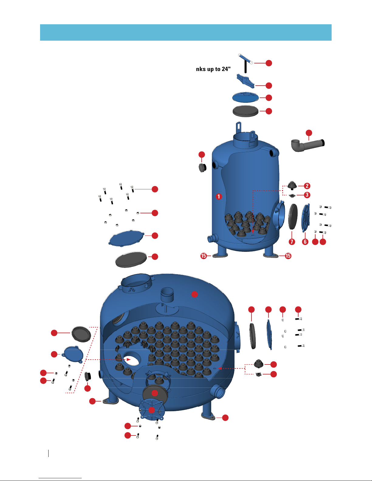
22 SANDSTORM™ SINGLE-/DOUBLE-CHAMBER USER MANUAL
REPLACEMENT PARTS
Tanks up to 24"
Tanks 30" and up
Tanks - double-chamber
1
5
4
10
11
14
7 6 13 12
16
1515
2
3
REV.
DESCRIPTION
DATE
Project:
Material:
1
2
3
5
121367
4
13
12
14
15
12
13
6
7
15
12
13
8
9
Page 23

SANDSTORM™ SINGLE-/DOUBLE-CHAMBER USER MANUAL 23
REPLACEMENT PARTS
Part Description Tank diameter (in) Cat. No.
1 Filter body Not available as spare part
2 Mushroom diffuser All 71915-000102
3 Mushroom rubber gasket All 71915-000103
4 Top service cover
6" 12 71915-000108
8"
16, 20, 24 71915-000109
30, 36 71915-000113
10" 48 71915- 000121
5 Top service cover gasket
6" 12 71915-000106
8" 16, 20, 24, 30, 36 71915-000107
10" 48 71915- 000121
6 Side service cover
6" 12, 16, 20 71915-000112
8" 24, 30, 36, 48 71915-000113
7 Side service cover gasket
6" 12, 16, 20 71915-000110
8" 24, 30, 36, 48 71915-000107
8 Bottom service cover 6" 48 71915-000112
9 Bottom service cover gasket 6" 48 71915-000110
10 Tightening bridge 12, 16, 20, 24 71915-000104
11 Tightening handle 12, 16, 20, 24 71915-000105
12 Bolt M12X50 All 71915-000114
13 Nut M12 All 71915-000115
14 2" male plug (plastic) All 75050-008800
15 Rubber leg cup All 71915-000136
16 PVC nipple and elbow
12 71915-000116
16 71915-000117
20 71915-000118
24 71915 - 000119
Page 24
24 SANDSTORM™ SINGLE-/DOUBLE-CHAMBER USER MANUAL
REPLACEMENT PARTS
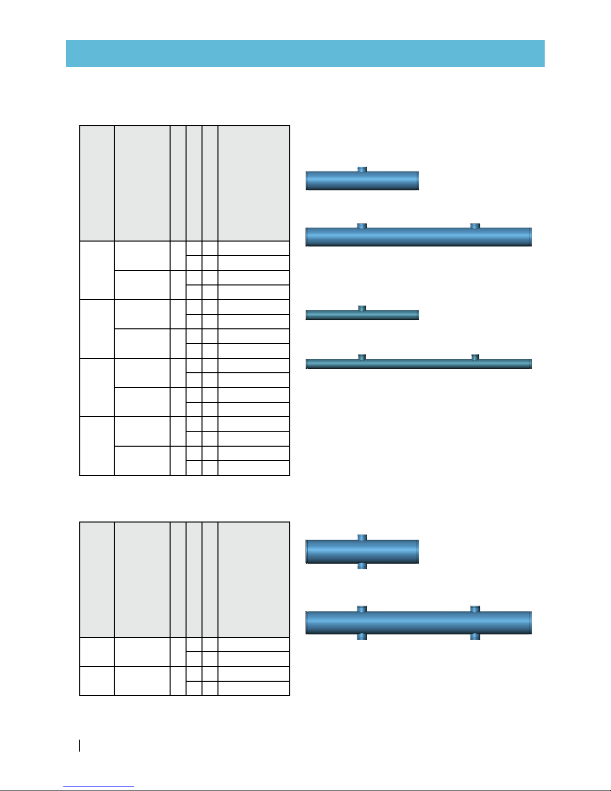
Manifold sections
2 outlets
4 outlets
Inlet/outlet manifold sections -
1 outlet
2 outlets
Backwash manifold sections -
1 outlet
2 outlets
Manifolds of other diameters are available upon request.
Tank diameter (in)
Type of
manifold
Manifold diameter (in)
Number of outlets
Outlet diameter (in)
Cat. No.
20
Inlet/outlet 4
2 2 71910-001706
3 2 71910- 001715
Backflush 3
2 2 71910- 0 01705
3 2 71910- 001714
24
Inlet/outlet 4
2 2 71910 -001708
3 2 71910 - 001717
Backflush 3
2 2 71910- 0 01707
3 2 71910-001716
30-36
Inlet/outlet 6
1 3 71910-001701
2 3 71910-001710
Backflush 3
1 2 71910-001700
2 2 71910 -001709
48
Inlet/outlet 8
1 4 71910- 0 0170 4
2 4 71910-001713
Backflush 4
1 3 71910- 0 01703
2 3 71910- 001712
Double-sided manifold sections
Outlet manifold sections for parallel centered installations only
Tank diameter (in)
Type of
manifold
Manifold's diameter (in)
Number of outlets
Outlet's diameter (in)
Cat. No.
30, 36 Inlet/outlet 8
2 3 71910-007000
4 3 71910-000924
48 Inlet/outlet 10
2 4 71910-000050
4 4 71910-000051
Single-sided manifold sections
Page 25
SANDSTORM™ SINGLE-/DOUBLE-CHAMBER USER MANUAL 25
REPLACEMENT PARTS
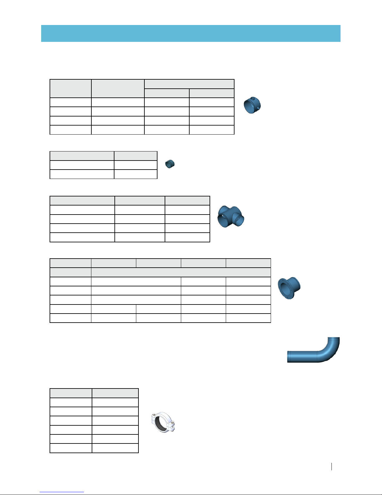
Manifolds accessories
Elbows
Backflush manifold end-caps
End-cap diameter (in) Cat. No.
3 71910-001791
4 71910- 0 01792
Flange-grooved coupling adaptors
Standard › ISO10 ISO16 ANSI BSTD
Diameter (in) Cat. No.
3 71910-002005 71910-002003 71910-002004
4 71910-002008 71910-002006 71910-002007
6 71910 - 00 2011 71910-002009 71910 -002010
8 71910-002014 71910-0020 40 71910 - 0 0 2012 71910-002013
10 71910 - 0 02017 71910-002018 71910 - 0 02015 71910 - 002016
Inlet and outlet manifold end-caps
End-cap
diameter (in)
Female threaded
outlets
Cat. No.
BSP NPT
4 3 x 1" 71910-001801 71910 - 0 018 00
6 2 x 2" + 1 x 1" 71910-00180 3 71910-001802
8 2 x 2" + 1 x 1" 71910-00180 5 71910 - 0 018 04
10 2 x 2" + 1 x 1" 71910 - 001820 71910 - 001821
T-fittings (adaptors)
T-fitting diameter (in) T-fitting outlets Cat. No.
8 2 x 6" 71910 - 0 01801
10 2 x 6" 71910 - 001803
10 2 x 8" 71910 - 001805
14 2 x 10" 71910 - 0 018 20
To order this spare part, call your local Netafim™ representative with the SKU (Stock
Keeping Unit) number of your SandStorm™ filtration system at hand.
Only with
this number can we supply the correct part for your specific system.
Find the SKU
number on your system order form.
Diameter (in) Cat. No.
2 71910-002500
3 71910-0025 01
4 71910-002502
6 71910-002503
8 71910-002504
10 71910-0025 05
Grooved couplings
Page 26

26 SANDSTORM™ SINGLE-/DOUBLE-CHAMBER USER MANUAL
For double-chamber tanks
Tank
diameter
(in) For manifold Cat. No.
20
Inlet 71910-001906
Outlet for straight systems 71910 - 0 018 99
Backflush 71910 - 0 01890
24
Inlet 71910-001906
Outlet for straight systems 71910 - 0 018 99
Outlet for parallel systems 71910-001967
Backflush 71910 - 0 01890
30
Inlet 71910 - 0 019 60
Outlet for straight systems 71910 - 0 019 09
Backflush 71910 - 0 01891
36
Inlet 71910 - 0 019 60
Outlet for straight systems 71910 - 0 019 09
Outlet for parallel systems 71910-001916
Backflush 71910 - 0 01891
48
Inlet 71910 - 0 01924
Outlet for straight systems 71910 - 0 01917
Outlet for parallel systems 71910-001928
Backflush 71910 - 0 01951
Support legs
For single-chamber tanks
Tank
diameter
(in) For manifold Cat. No.
30
Inlet 71910 - 0 019 65
Outlet for straight systems 71910 - 0 019 08
Backflush 71910 - 0 01893
36
Inlet 71910 - 0 019 65
Outlet for straight systems 71910 - 0 019 09
Backflush 71910 - 0 01893
48
Inlet 71910 - 0 01971
Outlet for straight systems 71910 - 0 01970
Backflush 71910 - 0 01952
REV.
DESCRIPTION
DATE
APPROVED
Drawing No.
Project:
General Tolerance According to ISO 2768-f
LINEAR DIMENSIONS
Part No.
Drawn By
Designed By
MA-6-200
08 Jan 2017
Barga
Subject:
Part Name:
Material:
Finish:
PROPRIETARY AND CONFIDENTIAL
THE INFORMATION CONTAINED IN THIS
DRAWING IS THE SOLE PROPERTY OF
NETAFIM. ANY REPRODUCTION IN PART
OR AS A WHOLE WITHOUT THE WRITTEN
PERMISSION OF NETAFIM IS PROHIBITED
/1
Quantity:
REV.
DESCRIPTION
DATE
APPROVED
Project:
Material:
REPLACEMENT PARTS
Page 27
SANDSTORM™ SINGLE-/DOUBLE-CHAMBER USER MANUAL 27
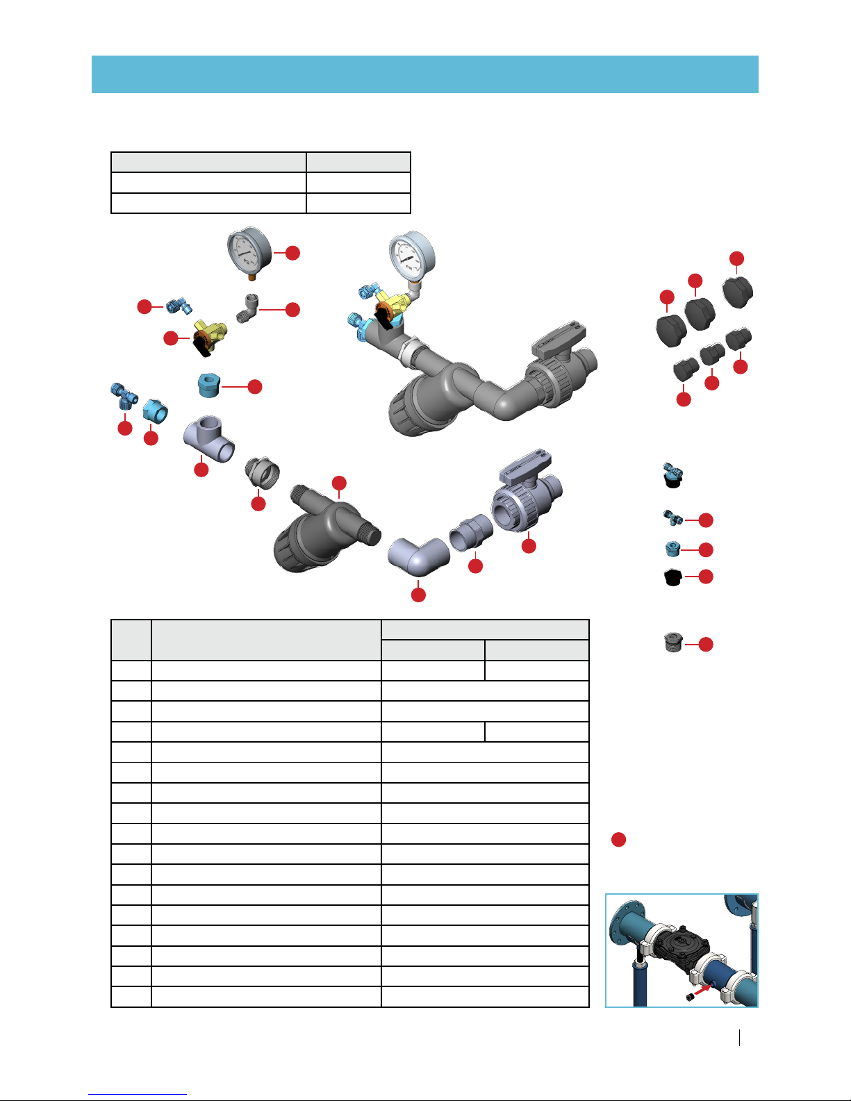
REPLACEMENT PARTS
Control kit
12
3
2
11
9
10
8
1
3
7
6
5
4
15
15
15
16
16
16
14
3
13
Description Cat. No.
1" Control kit (BSP connection) 37090-009600
1" Control kit (NPT connection) 37090-009610
Part Description
Cat. No.
BSP NPT
1 NMV PVC ball valve 1 union 1" FMT 77450-000121 77450-000150
2 PVC double nipple 1" 77400-017800
3 PVC 90 deg threaded elbow 1" 77400-016200
4 Filter 1" 80 mesh blue inox 76240-004050 76240-004080
5 PVC threaded reducer 3/4M*1F 7740 0 - 0 11350
6 PVC 90 deg threaded Tee 3/4" 77400-013700
7 Bushing 3/4m * 1/4f 76400-009600
8 Male run tee 8*8*1/4" 76400-004560
9 S.Y-3 1/4F (1/ 8F*1/8 F*1/4M) 76040-001400
10 Male elbow 8*1/8" 76400-003400
11 Pressure gauge 250 GLZ 10 bar 1/4" 77540-003400
12 Brass elbow M.F. 1/4" 78300-002700
13 Plastic bushing 1M * 3/4F 78220-004600
14 Male branch Tee 8*1/4" 76400-004500
15 Plastic male threaded plug 2" 78220-006300
16 Plastic male threaded plug 1" 78220-006100
17 Galvanized bushing 3/4*1/4"* 78200-010490
Parts
*17 Only for systems
equipped with a hydraulic
flow- control valve.
17
Page 28

28 SANDSTORM™ SINGLE-/DOUBLE-CHAMBER USER MANUAL
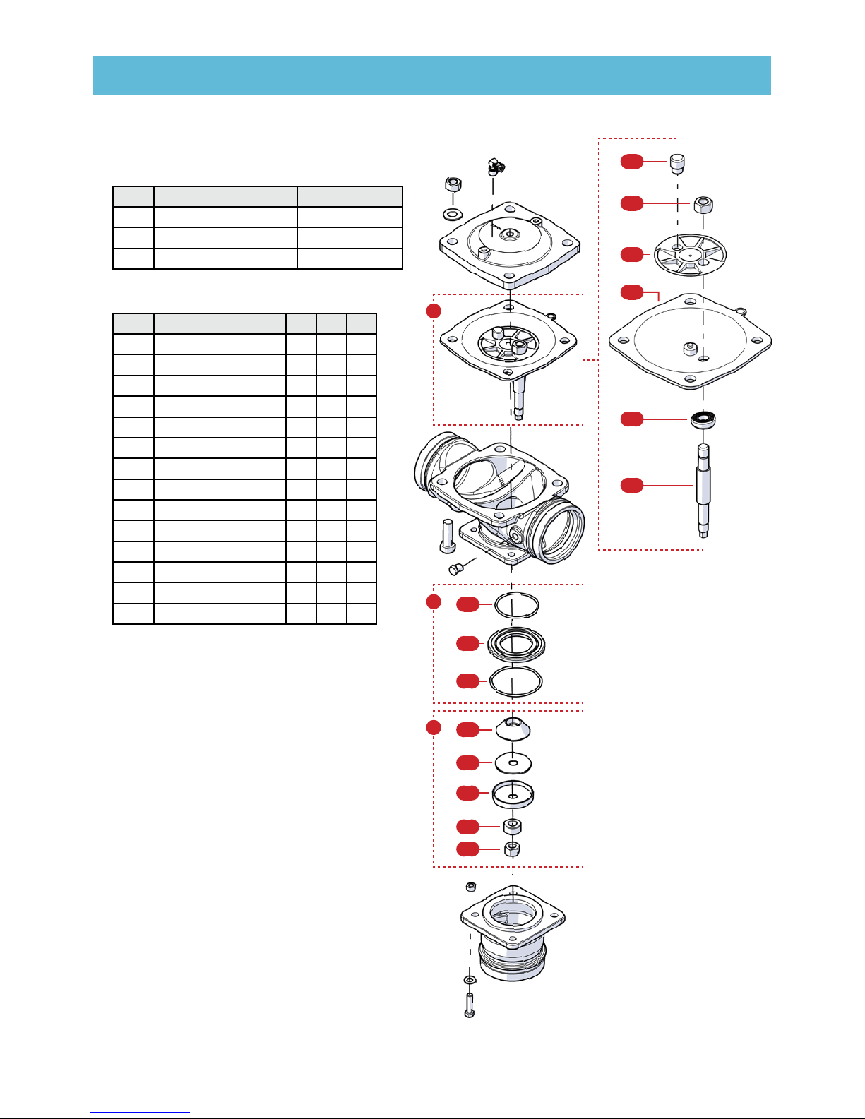
Part Description Cat. No.
1 Operator assembly 71680-006595
2 Body BSP 71680 - 001715
3 Plug 71610-000800
4 Grooved adaptor BSP 71680-015710
5 O-ring 716 80 - 014 350
6 Elbow 8 x 1/4 in 76400-003500
REPLACEMENT PARTS
Backwash 3-way hydraulic valve - 2"
Description Cat. No.
3-way hydraulic valve, 2" 71600-006515
Main parts
54
3
2
5
4
6
1
Page 29
SANDSTORM™ SINGLE-/DOUBLE-CHAMBER USER MANUAL 29
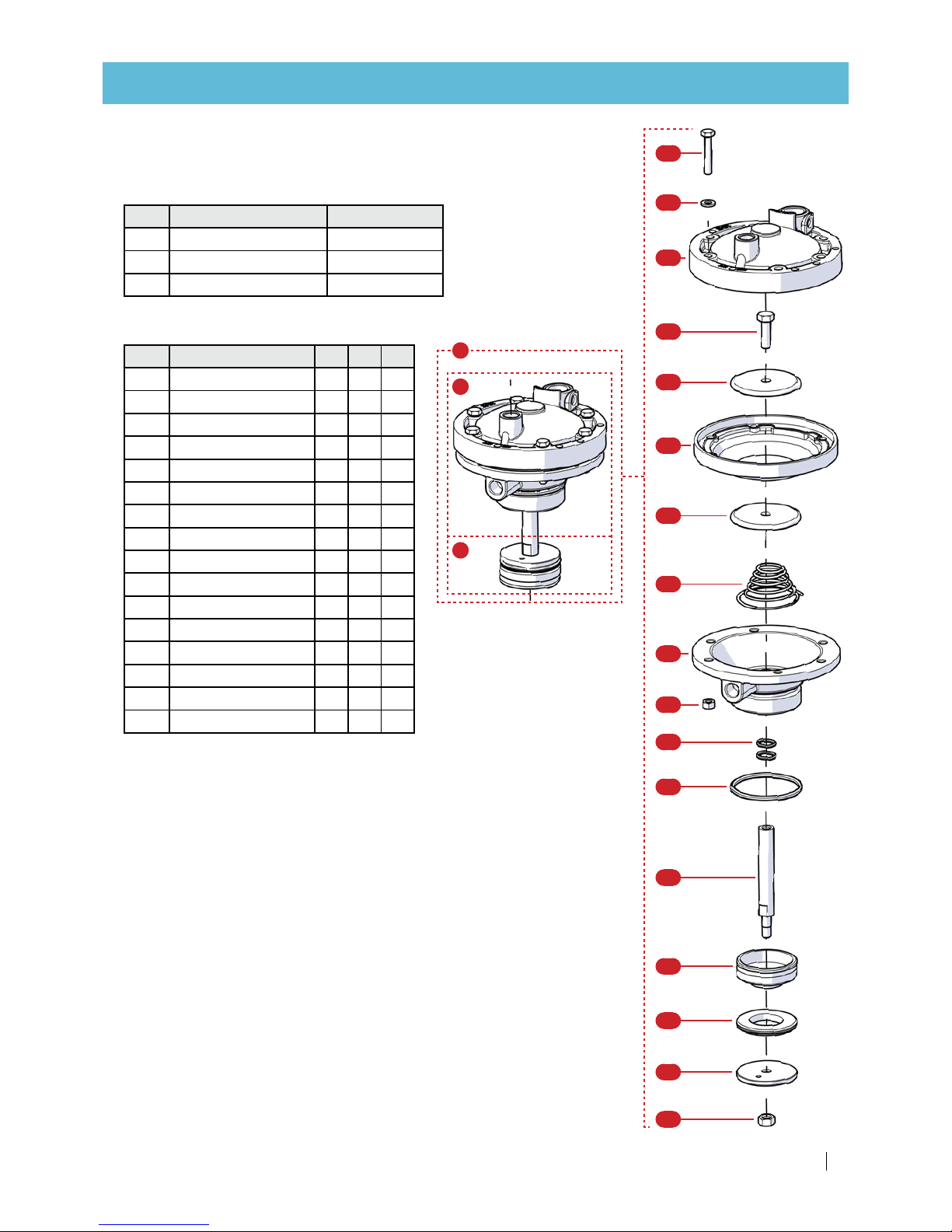
REPLACEMENT PARTS
1.6
1.1
1.15
1.2
1.4
1.5
1.3
1.5
1.7
1.16
1.8
1.9
1.10
1.11
1.12
1.13
1.14
1
1b
1a
Assemblies
Part Description Cat. No.
1 Operator assembly 71680-006595
1a Diaphragm assembly 71680-007480
1b Plug kit 716 8 0 - 001720
Assemblies - sub-parts
part Description
1 1a 1b
1.1 Bolt +
1.2 Bonnet +
1.3 Spring No. 51 +
1.4 Bolt + +
1.5 Diaphragm disc + +
1.6 Diaphragm No. 337 + +
1.7 Actuator body +
1.8 O-ring + +
1.9 O-ring + +
1.10 Shaft + +
1.11 Valve disc + +
1.12 Seal + +
1.13 Seal disc + +
1.14 Nut + +
1.15 Washer +
1.16 Nut M6 +
Page 30

30 SANDSTORM™ SINGLE-/DOUBLE-CHAMBER USER MANUAL
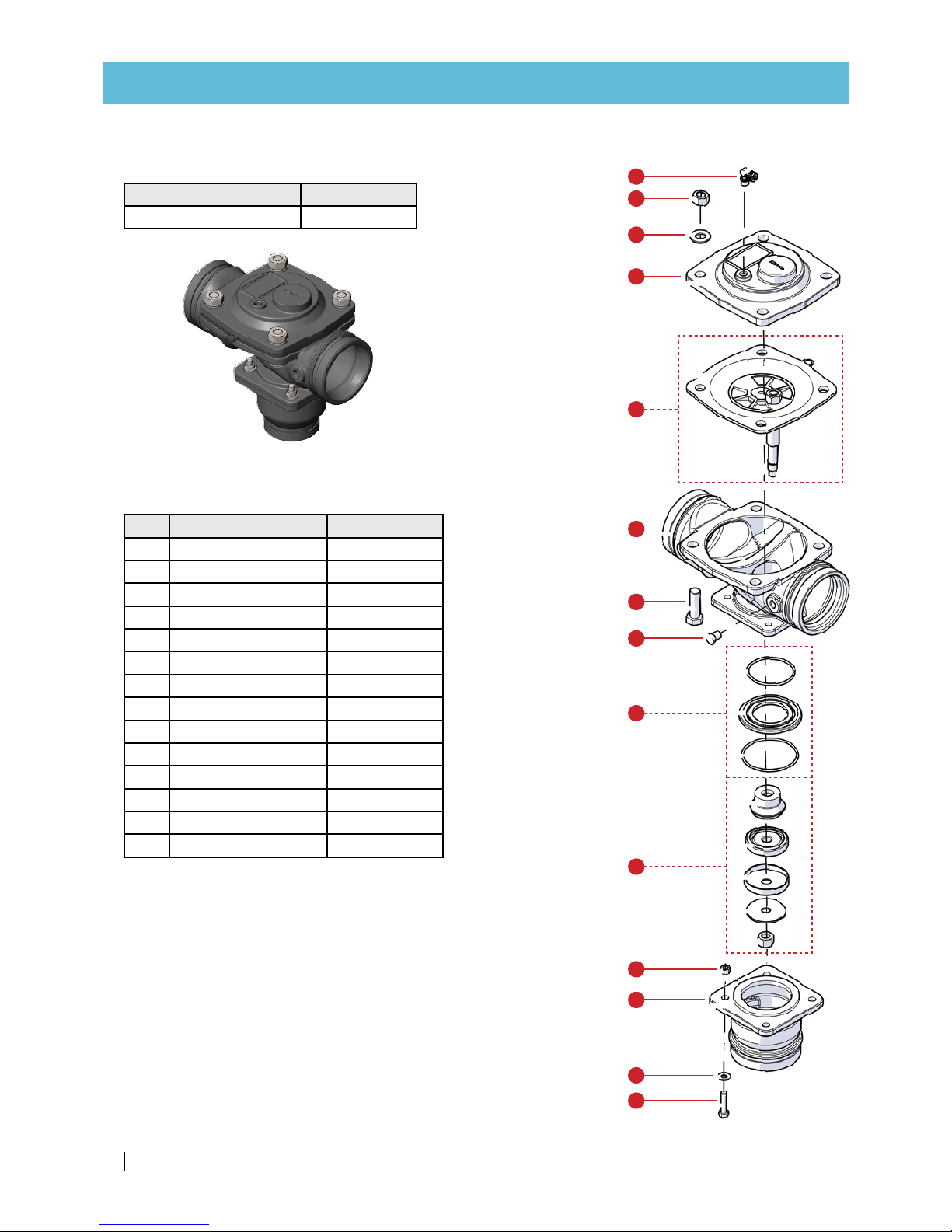
Backwash 3-way hydraulic valve - 3"
Description Cat. No.
3-way hydraulic valve, 3" 71600-006670
REPLACEMENT PARTS
Main parts
Part Description Cat. No.
1 Bolt 5/8*50 steel 71680-0 01710
2 Washer 5/8 76540-001100
3 Nut 5/8 76540-001000
4 Bonnet 71680 - 001721
5 Diaphragm assembly 71680-00775 0
6 Body 716 80 - 0129 25
7 Plug 71610-000800
8 Seat kit 71680 - 001713
9 Plug kit 71680- 0 017 23
10 BSP adaptor 716 8 0 -001722
11 Nut 716 8 0 -01170 0
12 Washer 7168 0 - 01160 0
13 Bolt 716 8 0 -0115 4 0
14 Elbow 8x1/4 in 76400-003500
6
5
4
2
3
14
1
7
8
11
9
10
12
13
Page 31
SANDSTORM™ SINGLE-/DOUBLE-CHAMBER USER MANUAL 31
REPLACEMENT PARTS
Part Description Cat. No.
5 Diaphragm assembly 71680-00775 0
8 Seat kit 71680 - 001713
9 Plug kit 71680- 0 017 23
Assemblies
Assemblies - sub-parts
part Description
5 8 9
5.1 Support pin +
5.2 Nut +
5.3 Top disc +
5.4 Diaphragm +
5.5 Shaft disc +
5.6 Shaft +
8.1 O-ring +
8.2 Seat +
8.3 O-ring +
9.1 Guide cone +
9.2 Seal +
9.3 Seal bowl +
9.4 Spacer +
9.5 Nut +
5
8
9
9.3
9.4
9.2
9.1
9.5
8.3
8.2
8.1
5.1
5.2
5.3
5.4
5.5
5.6
Page 32
32 SANDSTORM™ SINGLE-/DOUBLE-CHAMBER USER MANUAL
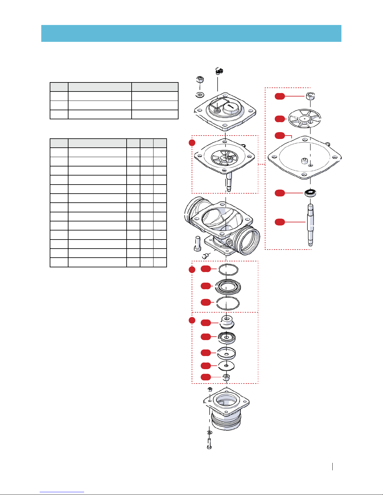
Backwash 3-way hydraulic valve - 4"
Description Cat. No.
3-way hydraulic valve, 4" 71600-006660
Main parts
6
5
4
2
3
14
1
7
8
11
9
10
12
13
REPLACEMENT PARTS
Part Description Cat. No.
1 Bolt 5/8*50 steel 71680-0 01710
2 Washer 5/8 76540-001100
3 Nut 5/8 76540-001000
4 Bonnet 71680 - 001711
5 Diaphragm assembly 71680-007800
6 Body ????????????
7 Plug 71610-000800
8 Seat kit 71680 - 001713
9 Plug kit 71680 -001714
10 Adaptor 71680-016091
11 Nut 716 8 0 -01170 0
12 Washer 7168 0 - 01160 0
13 Bolt 716 8 0 -0115 4 0
14 Elbow 8x1/4 in 76400-003500
Page 33
SANDSTORM™ SINGLE-/DOUBLE-CHAMBER USER MANUAL 33
Part Description Cat. No.
5 Diaphragm assembly 71680-007800
8 Seat kit 71680 - 001713
9 Plug kit 71680 -001714
REPLACEMENT PARTS
Assemblies
Assemblies - sub-parts
5
8
9
9.3
9.4
9.2
9.1
9.5
8.3
8.2
8.1
5.5
5.1
5.2
5.3
5.4
part Description
5 8 9
5.1 Nut +
5.2 Top disc +
5.3 Diaphragm +
5.4 Shaft disc +
5.5 Shaft +
8.1 O-ring +
8.2 Seat +
8.3 O-ring +
9.1 Guide cone +
9.2 Seal +
9.3 Seal bowl +
9.4 Washer +
9.5 Nut +
Page 34
34 SANDSTORM™ SINGLE-/DOUBLE-CHAMBER USER MANUAL
REPLACEMENT PARTS
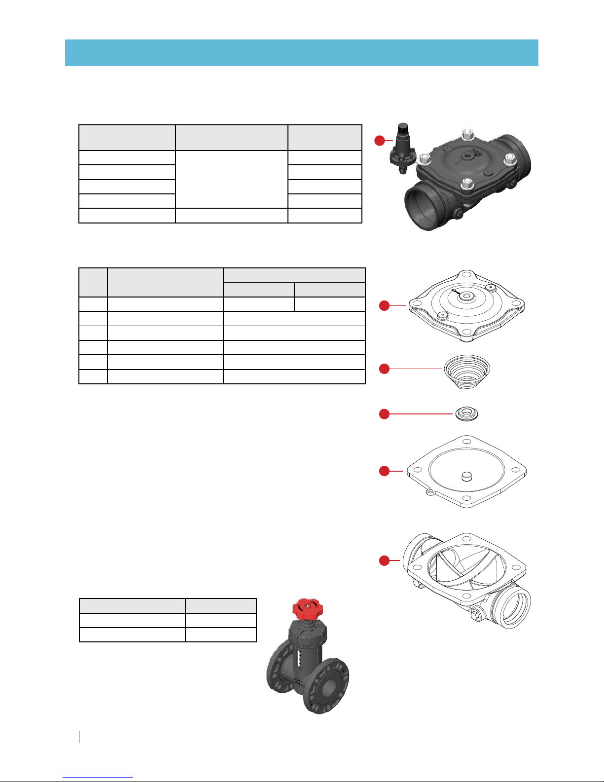
Backwash flow-control valve
Hydraulic flow-control valve
For filtration system
tank diameter
Description Cat. No.
20"
3" metal hydraulic valve
71600 - 052301
24" 71600 - 052302
30" 71600 - 05230 3
36" 71600-052300
48" 4" metal hydraulic valve 71600-004272
Part Description
Cat. No.
3" 4"
1 Body 71680-018281 71680-018282
2 Diaphragm 71680-006300
3 Spring disc 71680-008900
4 Spring 71680-008100
5 Bonnet 71680-009153
6 Flow control pilot 29-310 716 8 0 - 0 0 117 5
Main parts
Parts Catalog - 100
1
2
3
4
5
REV.
DESCRIPTION
DATE
APPROVED
Project:
Material:
Description Cat. No.
3" plastic throttle valve 71920-000100
4" plastic throttle valve 71920-000110
Manual flow-control valve
6
Page 35

SANDSTORM™ SINGLE-/DOUBLE-CHAMBER USER MANUAL 35
BackFlush controller
Description Cat. No.
DC 2 outputs with DP sensor 73240 - 0 0 3175
DC 4 outputs with DP sensor 73240 - 0 0 3178
DC 6 outputs with DP sensor 73240 - 0 0 3179
DC 8 outputs with DP sensor 7324 0 - 003181
DC 10 outputs with DP sensor 73240-00 3182
BackFlush controller
Description Cat. No.
DC 2 output expansion card 73240 - 0 0 317 7
Power supply 100-240VAC/12VDC 1A 73240 -007240
BackFlush controller accessories
REPLACEMENT PARTS
DC actuator valve
Description Cat. No.
Aquativ DC actuator valve 35500-001925
Netafim™ Air Valve
6
5
4
3
2
1
ARI Air Valve
Air Valve
Inlet diameter
(in)
Cat. No.
BSP NPT
1 32600-004000 70561-001200
2 32600-002000 70561-001500
Page 36
36 SANDSTORM™ SINGLE-/DOUBLE-CHAMBER USER MANUAL
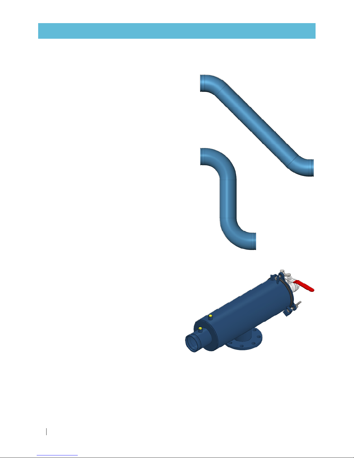
Inlet adaptor pipe
45°
90°
To order this spare part, call your local Netafim™
representative with the SKU (Stock Keeping Unit)
number of your SandStorm™ filtration system at hand.
Only with this number can we supply the correct part
for your specific system.
Find the SKU number on your
system order form.
REPLACEMENT PARTS
6
5
4
3
2
1
Secondary screen filter
Secondary filter
To order this part, call your local Netafim™
representative with the SKU (Stock Keeping Unit)
number of your SandStorm™ filtration system at hand.
Only with this number can we supply the correct part
for your specific system.
Find the SKU number on your
system order form.
Page 37

SANDSTORM™ SINGLE-/DOUBLE-CHAMBER USER MANUAL 37
WARRANTY
Netafim™ warrants all the components of the SandStorm™ media filter system to be free of defects in
material and workmanship for 5 (five) years from the date of installation.
If a defect is discovered during the applicable warranty period, Netafim™ will repair or replace, at its
discretion, the product or the defective part.
This warranty does not extend to repairs, adjustments or replacements of a Netafim™ media filter system
or part that results from misuse, negligence, alteration, force majeure, lightning, power surge, improper
installation or improper maintenance.
If a defect arises in your Netafim™ product during the warranty period, contact your local Netafim™
representative.
Limited warranty
This warranty is subject to the conditions in Netafim's official warranty statement.
(For the full text of Netafim's official warranty statement, please contact your local Netafim™
representative).
Page 38

GROW MORE WITH LESS
WWW.NETAFIM.COM
 Loading...