

Page 1
Page 2

NMC-PRO
© COPYRIGHT 2011, NETAFIM
NO PARTS OF THIS PUBLICATION MAY BE REPRODUCED, STORED IN AN AUTOMATED DATA FILE OR MADE PUBLIC IN
ANY FORM OR BY ANY MEANS, WHETHER ELECTRONIC, MECHANICAL, BY PHOTOCOPYING, RECORDING OR IN ANY
OTHER MANNER WITHOUT PRIOR WRITTEN PERMISSION OF THE PUBLISHER.
ALTHOUGH NETAFIM TAKES THE GREATEST POSSIBLE CARE IN DE S IGNING AND PRODUCING BOTH ITS PRODUCTS
AND THE ASSOCIATED DOCUMENTATION, THEY MAY STILL INCLUDE FAULTS.
NETAFIM WILL NOT ACCEPT RESPONSIBILITY FOR DAMAGE RESULTING FROM THE USE OF NETAFIM'S PRODUCTS OR
THE USE OF THIS MANUAL.
NETAFIM RESERVES THE RIGHT TO MAKE CHANGES AND IMPROVEMENTS TO ITS PRODUCTS AND/OR THE
ASSOCIATED DOCUMENTATION WITHOUT PRIOR NOTICE.
User Manual
Page 2
Page 3

NMC-PRO
CONTENTS
Table of Contents
1 General Information ................................................................................................................................................ 5
1.1 Keyboard .............................................................................................................................................................. 5
1.2 Hot Screens ......................................................................................................................................................... 5
1.3 Main Menu Icons .................................................................................................................................................. 6
1.4 Introduction to Irrigation Programs ....................................................................................................................... 7
1.5 Operation Mode ................................................................................................................................................... 7
2 PROGRAM MENU ......................................................................................................................................................... 9
2.1 Run Time Program ............................................................................................................................................... 9
2.2 Dosing Program ................................................................................................................................................. 11
2.2.1 Proportional Quantity ................................................................................................................................. 11
2.2.2 Proportional Time ...................................................................................................................................... 12
2.2.3 Time ........................................................................................................................................................... 12
2.2.4 Quantity ..................................................................................................................................................... 13
2.2.5 EC Pre-Control .......................................................................................................................................... 16
2.3 Irrigation Program .............................................................................................................................................. 17
2.3.1 Setting Valve Sequence ............................................................................................................................ 18
2.3.2 Adjusting the Water Quantity Based on Weather Conditions ................................................................... 20
2.3.3 Configuring the Irrigation Cale ndar ........................................................................................................... 21
2.4 Irrigation Based on External Conditions ............................................................................................................. 22
2.4.1 Setting the Dry Contacts ........................................................................................................................... 23
2.4.2 Configuring the Analog Sensor s ................................................................................................................ 24
2.5 Irrigation Based on Radiation Sum .................................................................................................................... 27
2.6 Irrigation Based on VPD Sum ............................................................................................................................ 28
2.7 Introduction to the Influence Program ................................................................................................................ 29
2.8 Using the Influences ........................................................................................................................................... 29
2.8.1 Setting the Influences ................................................................................................................................ 29
2.8.2 Radiation Influence on Target EC ............................................................................................................. 30
2.8.3 Drainage Influence on Target Radiation Sum ........................................................................................... 31
2.8.4 Drain Influence on Minimum Time ............................................................................................................. 32
2.8.5 Drainage EC Level Influence on Target EC .............................................................................................. 33
2.8.6 VPD Influence on Target EC ..................................................................................................................... 35
2.8.7 Temperature Influence on Target EC ........................................................................................................ 36
2.9 Agitator ............................................................................................................................................................... 37
2.10Selector................................................................................................................................................................. 38
2.11Filter Flushing ....................................................................................................................................................... 38
2.12Cooling.................................................................................................................................................................. 41
2.13Misting .................................................................................................................................................................. 42
User Manual
Page 3
Page 4

NMC-PRO
CONTENTS
2.14Water Heating ....................................................................................................................................................... 42
3 MANUAL MENU ......................................................................................................................................................... 43
3.1 System Pause .................................................................................................................................................... 43
3.2 Start/Stop Program ............................................................................................................................................ 43
3.3 Start/Stop Valve ................................................................................................................................................. 44
3.4 Manual Filter Flush ............................................................................................................................................. 45
4 ALARM MENU ............................................................................................................................................................ 46
4.1 Reset .................................................................................................................................................................. 46
4.2 Alarm History ...................................................................................................................................................... 47
4.3 Alarm Definition .................................................................................................................................................. 47
4.4 Alarm Setting ...................................................................................................................................................... 49
4.5 EC/pH Alarm Definition ...................................................................................................................................... 49
4.6 EC/pH Alarm Setting .......................................................................................................................................... 49
4.7 Radio System Alarm Definition .......................................................................................................................... 50
4.8 Radio System Alarm View .................................................................................................................................. 50
4.9 Sms Subscription ............................................................................................................................................... 51
5 HISTORY MENU ......................................................................................................................................................... 52
5.1 Irrigation Log ...................................................................................................................................................... 53
5.2 RAD. & VPD SUM & Drain Log .......................................................................................................................... 54
5.3 Uncompleted Irrigation ....................................................................................................................................... 55
5.4 Uncompleted Program s ..................................................................................................................................... 56
5.5 Daily Irrigation .................................................................................................................................................... 56
5.6 Irrigation Accumulation ....................................................................................................................................... 57
5.7 Aux Meter Accumulation .................................................................................................................................... 57
5.8 Accumulation Reset ........................................................................................................................................... 57
5.9 Filters .................................................................................................................................................................. 58
5.10 Cooling ............................................................................................................................................................... 58
5.11 Sensor Log ......................................................................................................................................................... 59
5.12 Event Log ........................................................................................................................................................... 59
5.13 System Log ........................................................................................................................................................ 59
User Manual
Page 4
Page 5
NMC-PRO
GENERAL INFORMATION
1 0BGENERAL INFORMATION
• Keyboard
• Hot Screens
• Main Menu Icons
• Introduction to Irrigation Programs
• Operation Mod e
1.1 5BKeyboard
Numer keys: Use these ke ys to enter values or quantities. In addition, they act as
shortcuts to selections (see the following section).
+/- Key: Toggles between positive and negative values and marks check boxes' option
selection. In a History screen, use this key to toggle between quantities and time
format.
Arrows: Scroll up, down, left, and right to select menus.
MENU: Press to get to the main menu; also acts as "ESC" and "Back" keys.
ENTER: Enter menu, submenu, value, open window, and confirm a value or change.
ZONE LOG IN: Access Mode
DELETE: Erases s t yp in g mistake.
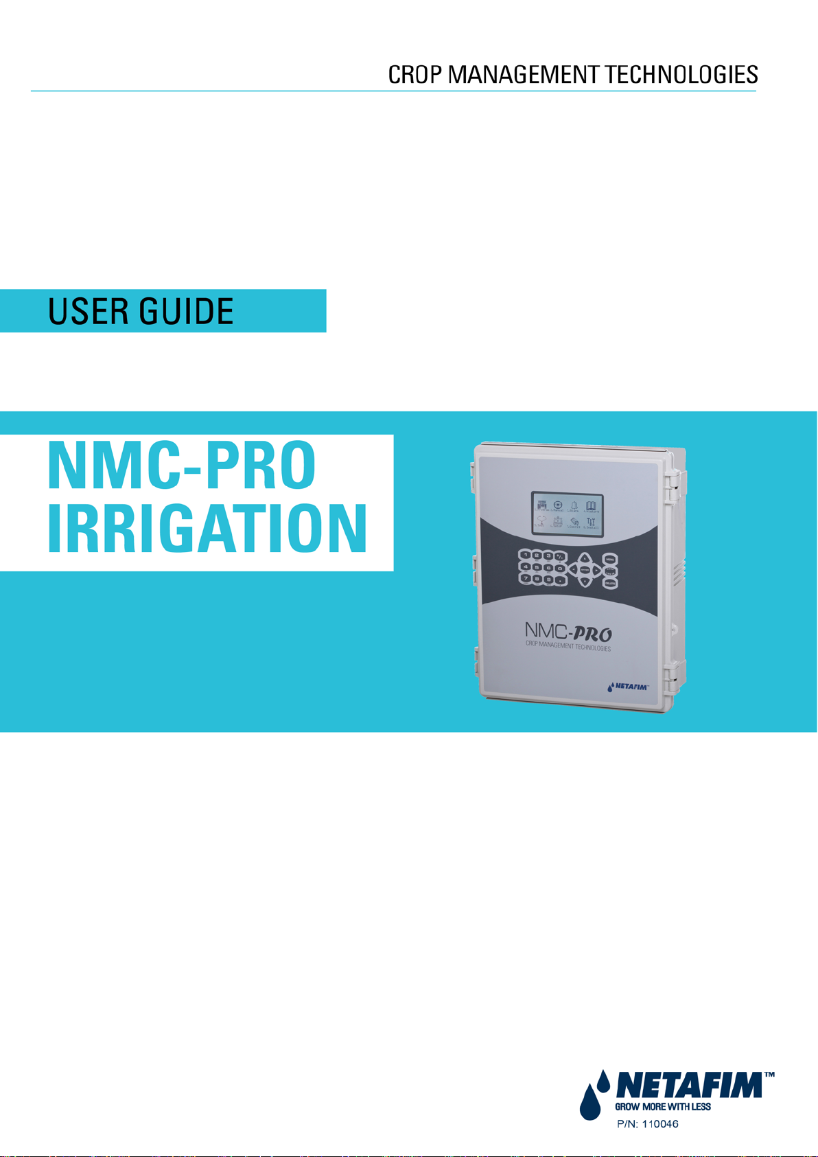
1.2 6BHot Screens
Press MENU from the Main Menu to see Read-On ly overview running processes. Press MENU again to return to the
Main Menu.
There are 10 Hot Screens / Keys:
• 0: Hot Key- Icon of active actions/processes
• 1: Main Screen/System Status
• 2: Irrigation Process
• 3: Irrigation Program Status
• 4: Water, EC/pH, Dosing
• 5: Filter Flushing Status
• 6: Temperature & Humidity measurement
• 7: Weather Station measurement
• 8: System Pressure
• 9: Drain Status
User Manual
Page 5
Page 6
NMC-PRO
GENERAL INFORMATION
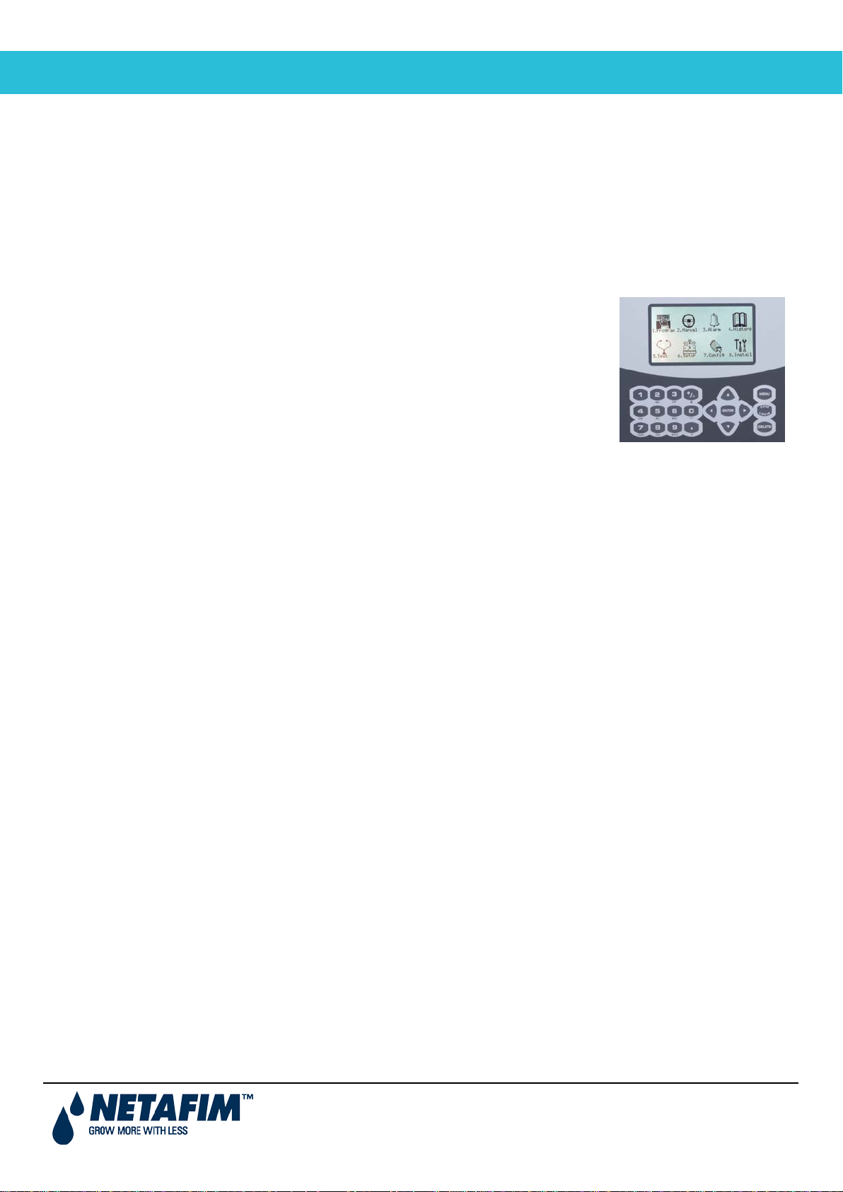
1.3 7BMain Menu Icons
Data log-
Programs:
Conduct manual
Set alarm
For
measurements
Manually test
1.Program
2.Manual
3.Alarm
4.History
5.Test
6.Setup
7.Config
8.Install
irrigation process,
filter flush, system
pause
threshold, and
reset
irrigation
regimen,
dosing recipe,
filter flushing,
entire program
field devices
(valves,
pumps…),
sensor values
(EC, pH, temp,
hum…)
System set-up,
time/date,
sensors
calibration, unit
irrigation log,
water meter,
and system
event log
professional
technical use
only
For
professional
technical use
only
User Manual
Page 6
Page 7
NMC-PRO
GENERAL INFORMATION
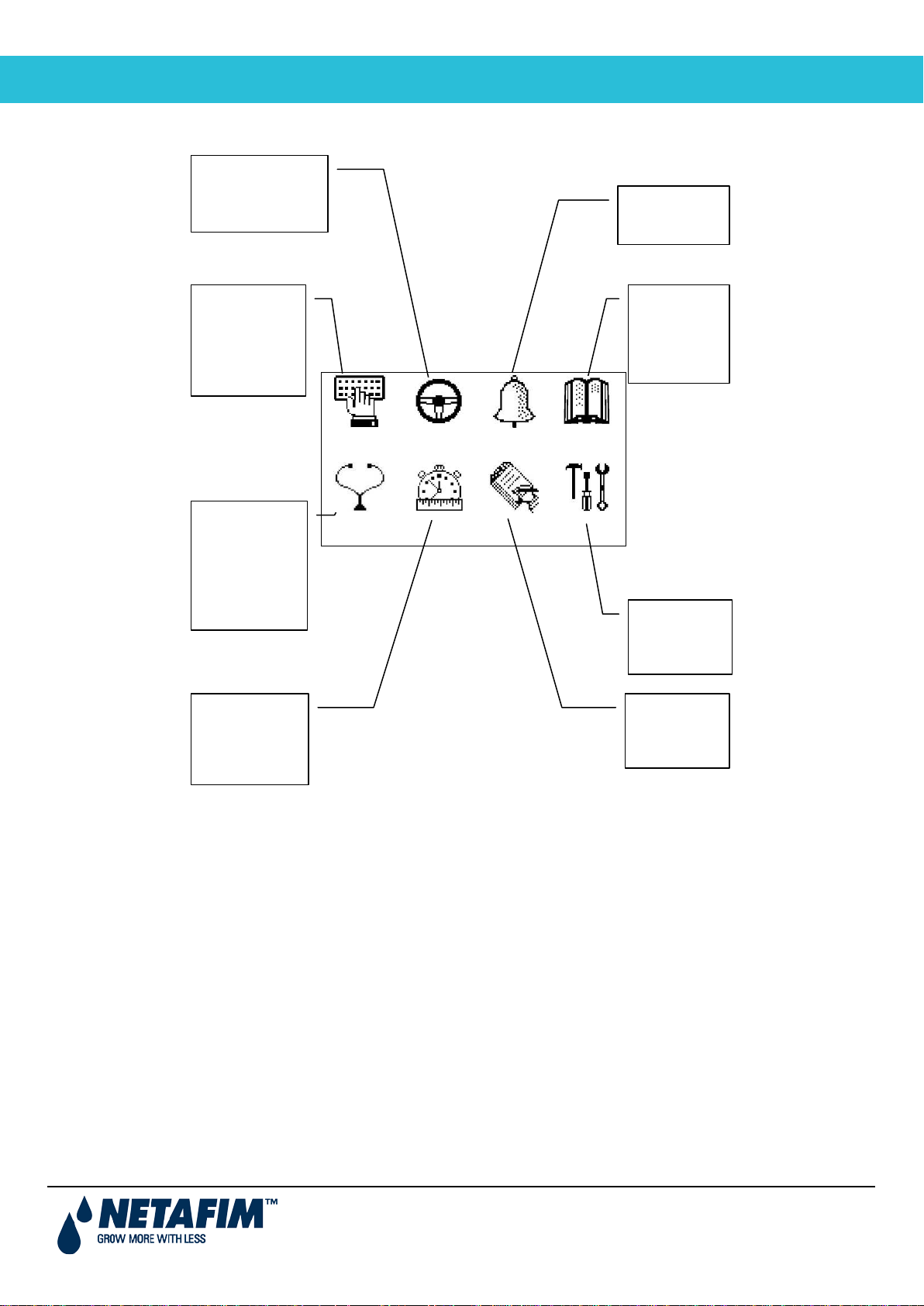
1.4 8BIntroduction to Irrigation Programs
To set an irrigation program-regiment/strategy, the grower must select the necessary valves and set the Run Time
and Dosing programs. The grower can define one or more programs for one or more valves. Refer to PROGRAM
MENU, page 9 for detailed information on these programs.
• Run Time Programs
Based on Time or Quantity
Set water before and after dosing process (fertilizer injection)
• Dosing Programs (Fertilizer)
Up to eight dosing channels per program
Each channel can be defined by:
o Quantity
o Proportional Quantity
o Time
o Proportional Time
• Irrigation Timing Based on External Condition Programs
Supports up to 15 programs
Each program defines:
o Time frame
o Trigger
o Trigger Type (for example one time only or multiple shots)
1.5 9BOperation Mode
There are three operation levels:
• Read Only (restricted): All the parameters and menus are visible, but cannot be modified
• User (partially restricted): Menus 1-6 are fully accessible and can be modified. Menus 7 and 8 can be
viewed but not modified
• Technician (unrestricted): All menus are fully accessible (no restrictions)
User Manual
Page 7
Page 8
NMC-PRO
GENERAL INFORMATION
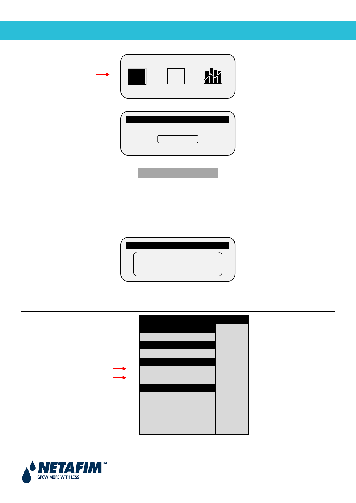
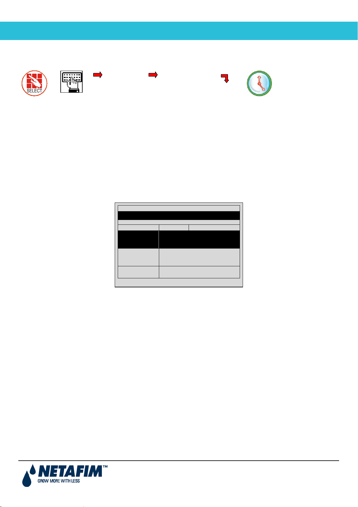
To change the operation mode, press the LOG IN key
MODE
PASSWORD
OPERATION MODE
OPERATION MODE – USER
?
1
2
3
OPERATION MODE
WRONG PASSWORD
Please Try Again.
Click the MODE icon and insert the password
Please Enter Password
The controller recognizes the operation mode according to the password that is entered:
Read Only 0000
User 9785 or 0101
If an incorrect password is entered, this screen appears.
The Operation mode can be configured to automatically return to the “Read-Only” mode after a certain amount of
time.
Note: Refer to the SYSTEM SETUP section in the Installation Manual.
SYSTEM SETUP
History Resolution ► 1 HOUR
Controller Function ► LOCAL
Automatic return to RO mode ► NO
Return period to RO mode ► 00:10
Controller Number ► 1
Lower Port – Protocol ► NMC NET
Lower Port – BaudRate ► 9600
Upper Port – Protocol ► NONE
Upper Port – BaudRate ► 9600
HISTORY
WEATHER STATION
OPERATION MODE
COMMUNICATION
• To perform a cold start or firmware upgrade, the controller must be in the “Technician” mode.
• If there is a power failure, the controller powers up with the last used mode.
User Manual
Page 8
Page 9

NMC-PRO
PROGRAM MENU
2 1BPROGRAM MENU
The Program Menu is used to configure the irrigation programs. Configuration is a multistep process consisting of
setting the following:
• Run Time Program (length of irrigation time or quantity of water to be distributed), page 9
• Dosing Program (fertilizer distribution program), page 11
• Irrigation (time frame and other parameters), page 17
In addition (or as alternative) to starting the irrigation based on time, irrigation can be set to begin based on:
• Irrigation Based on External Conditions, page 22
• Irrigation Based on Radiation Sum, page 27
• Irrigation Based on VPD Sum, page 28
Furthermore, you can adjust the irrigation process based on environmental factors such as the amount of radiation,
the temperature, or other factors. Refer to Introduction to the Influence Program and Introduction to the Influence
Program, page 29 for more details.
Lastly, use this menu to configure the following functions:
• Agitator, page 37
• Selector, page 38
• Filter Flushing, page 38
• Cooling, page 41
• Misting, pag e 42
• Water Heating, page 42
2.1 10BRun Time Program
For every irrigation program, define a Run Time program, which defines the how much water to distribute. Run Time
can be based on either length of time or quantity of water. You can define up to 60 Run Time programs.
As an option, you can configure irrigation to run for a certain amount of time or quantity before dosing begins and/or
after dosing ends. This process rinses the irrigation pipes of any residual matter.
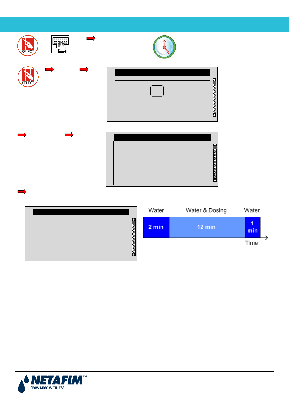
To set the irrigation Run Time:
1. Go to Program > Water Run Time.
2. Select QTY or TIME.
3. Enter the water quantity/total run time.
4. Enter the Before and/or After quantity/time (optional).
5. Repeat as required for each program.
User Manual
Page 9
Page 10
NMC-PRO
PROGRAM MENU
2. Water Run Time
Define
#
Method
Water
Before
After
1
QTY.
10.000
0.000
0.000
QTY.
TIME
#
Method
Water
Before
After
1
TIME
00:15:00
00:00:00
00:00:00
1. Program
Qty.
# Method Water Before After
2
3
4
5
6
7
8
WATER RUN TIME PROGRAM
QTY.
QTY.
QTY.
QTY.
QTY.
QTY.
QTY.
25.000
0.000
0.000
0.000
0.000
0.000
0.000
0.000
0.000
0.000
0.000
0.000
0.000
0.000
0.000
0.000
0.000
0.000
0.000
0.000
0.000
Time
2
3
4
5
6
7
8
WATER RUN TIME PROGRAM
QTY.
QTY.
QTY.
QTY.
QTY.
QTY.
QTY.
25.000
0.000
0.000
0.000
0.000
0.000
0.000
0.000
0.000
0.000
0.000
0.000
0.000
0.000
0.000
0.000
0.000
0.000
0.000
0.000
0.000
WATER RUN TIME PROGRAM
1
TIME
2
QTY.
3
QTY.
4
QTY.
5
QTY.
6
QTY.
7
QTY.
8
QTY.
o Define value for "before" and "after" time program
00:15:00
25.000
0.000
0.000
0.000
0.000
0.000
0.000
00:0200
5.000
0.000
0.000
0.000
0.000
0.000
0.000
00:01:00
5.000
0.000
0.000
0.000
0.000
0.000
0.000
Note: Whatever figure you enter in Before/After is deduc ted f rom the total run time/quantity. For example if the
run time is 15 minutes, a Before time of two minutes and After time of one minute, then the net dosing time is
12 minutes.
User Manual
Page 10
Page 11
NMC-PRO
PROGRAM MENU
2.2 11BDosing Program
3. Dosing
Program: 1
EC Dosing Method
P.TIME
P. QTY
Program: 1
1
2
3
---
1. Program
For every irrigation program, define a Dosing Program that defines the quantity of fertilizer per channel and its delivery
method. You can define up to 10 Dosing Programs.
Note: If there is more than one fertilizer tank for the selected dosing channel, refer to Selector, page 38.
DOSING PROGRA M
INJECTION PER DOSING CHANNEL
EC
5.00
EC Dosing Method
PH Dosing Method
EC
5.00
ACID
5.00
P.QTY
P.QTY
---
---
Dosing can be according to one of the following:
• Proportional quantity • Proportional time
• Quantity • Time
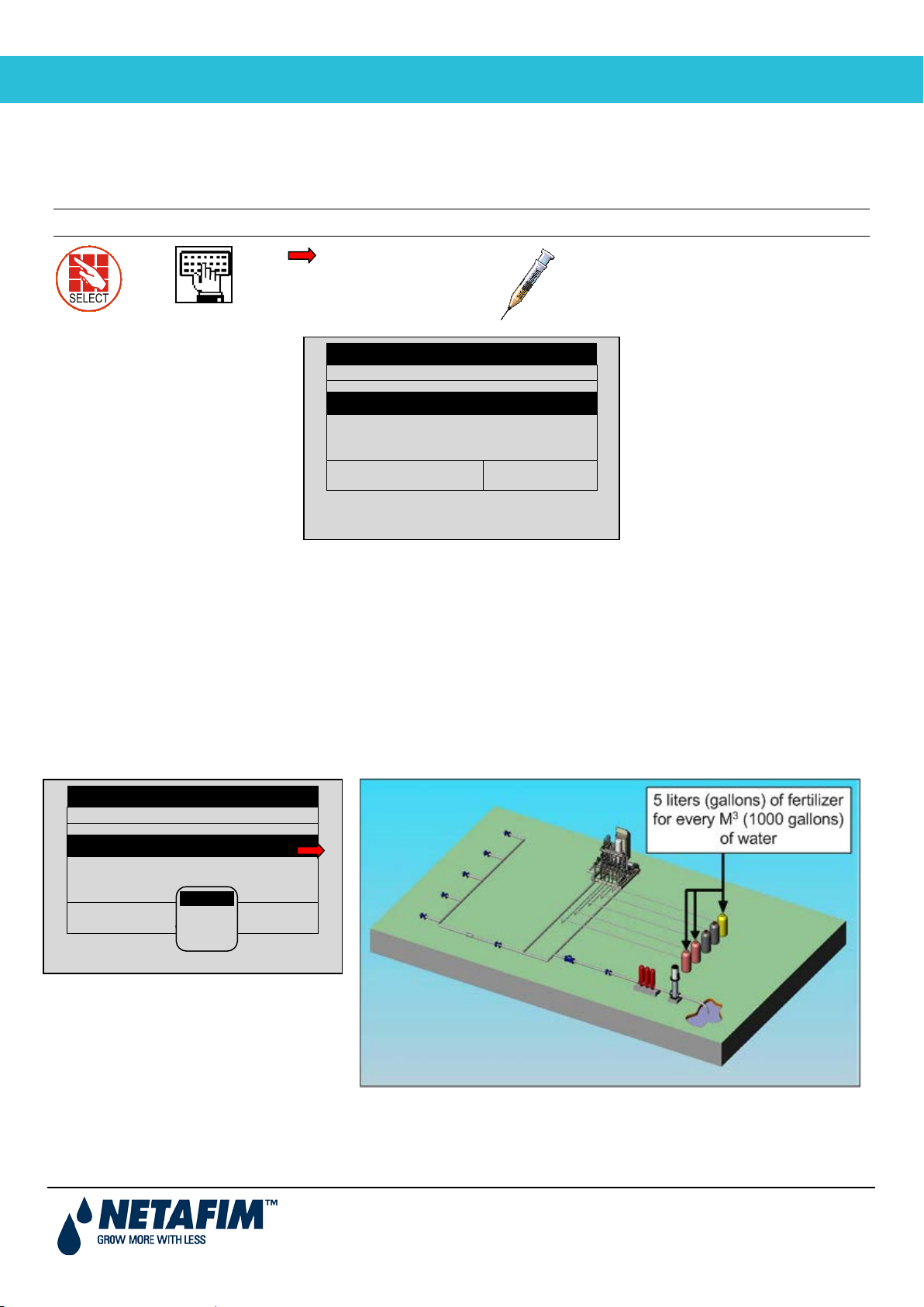
2.2.1 50BProportional Quantity
Proportional Quantity is the quantit y of fertilizer distributed per quantity of water. The proportion can be one of the
following:
• Liters per cube of water
• Gallons per 1000 gallons of water
DOSING PROGRA M
INJECTION PER DOSING CHANNEL
1
EC
5:00
PH Dosing Method
2
EC
6:00
3
ACID
0.00
P. TIME
P.QTY
TIME
---
---
---
User Manual
Page 11
Page 12
NMC-PRO
PROGRAM MENU
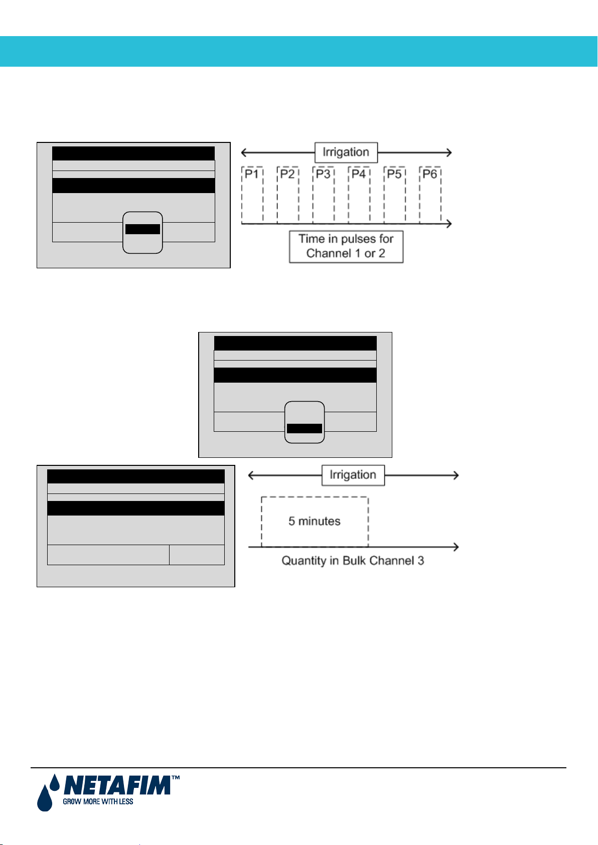
2.2.2 51BProportional Time
Example: In Channel 3, P1 = 5 minutes.
Program: 1
1
2
3
---
P. QTY
Program: 1
1
2
3
---
P. QTY
Program: 1
1
2
3
---
Proportional Time takes the required dosing time and spreads out each dose over the irrigation program in open/close
pulses per channel. The diagram below shows how each the fertilizer is distributed over the total run time; a dose (P)
is injected during irrigation according to the calculated schedule.
DOSING PROGRA M
INJECTION PER DOSING CHANNEL
EC
00:10
EC Dosing Method
PH Dosing Method
EC
00:00
P. TIME
TIME
ACID
0.00
P.TIME
P.QTY
---
---
2.2.3 52BTime
When using the Time delivery method, fertilizer is injected once, for the length of time defined in this screen.
DOSING PROGRA M
INJECTION PER DOSING CHANNEL
DOSING PROGRAM
INJECTION PER DOSING CHANNEL
EC
00:10
EC Dosing Method
PH Dosing Method
EC
00:00
P. TIME
TIME
ACID
0.00
P.TIME
P.QTY
---
---
EC
00:15
EC Dosing Method
PH Dosing Method
EC
00:10
(one pulse)
ACID
00:05
TIME
TIME
---
---
User Manual
Page 12
Page 13
NMC-PRO
PROGRAM MENU
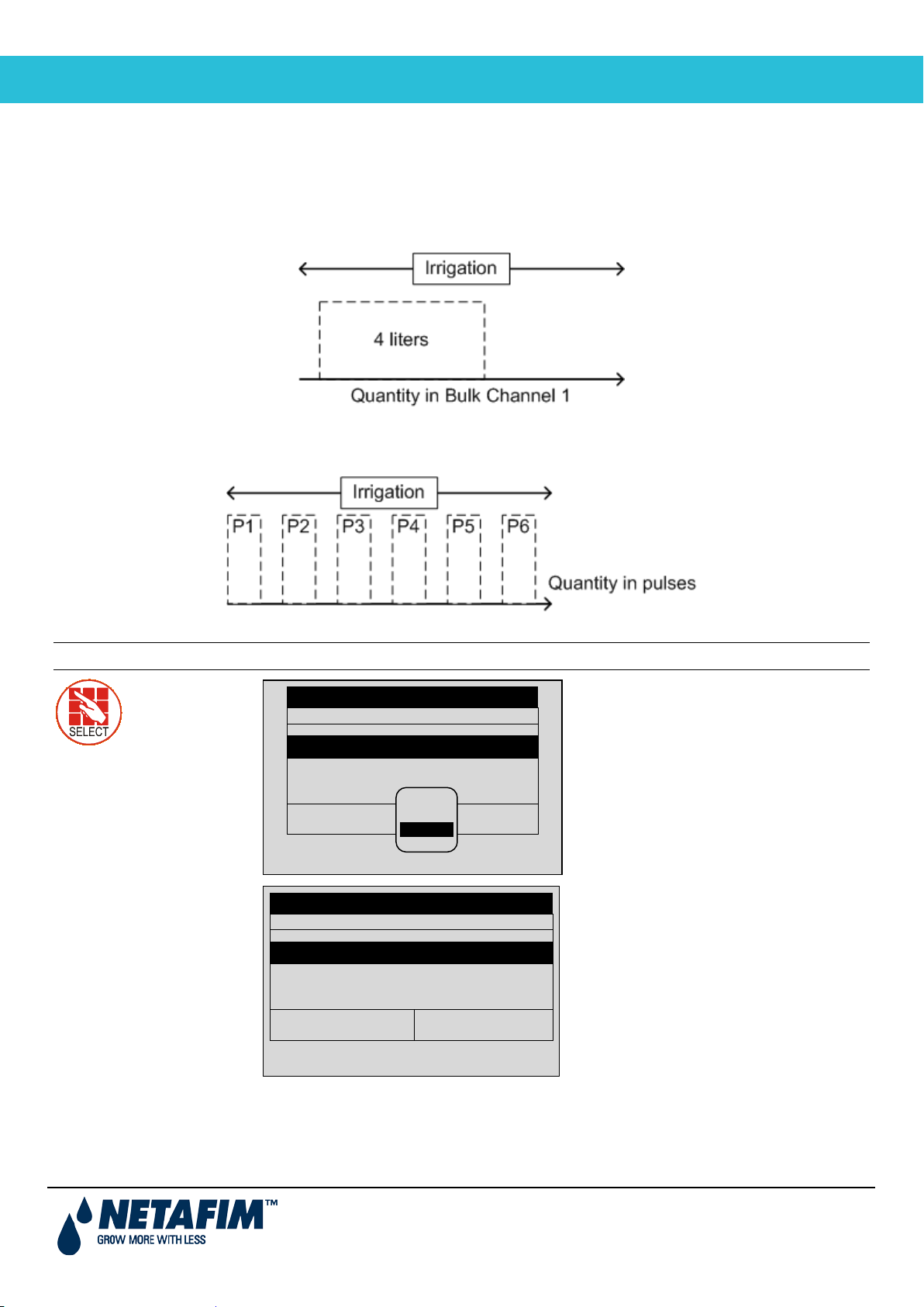
2.2.4 53BQuantity
Program: 1
1
2
3
--EC Dosing Method
QTY.
EC Dosing Method
P.TIME
P. TIME
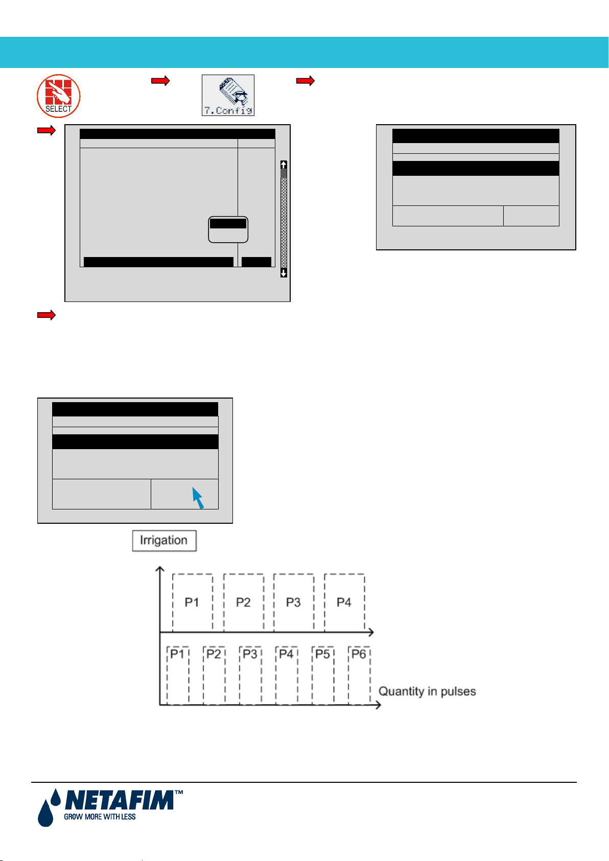
The Quantity method injects a fixed amount of fertilizer in the irrigation water. When using the Quantity method, there
are two options:
• Option A: Bulk (similar to Time method). In this option, fertilizer is injected once, with the quantity defined in
this screen.
Example: Channel 1, P1 = four liters in one pulse
• Option B: Spread (according to dosing configuration set by a technician). Option B is similar to Proportional
Time. In this method, fertilizer is spread out by quantity over the irr igat ion run time.
Example: Channel 1 = P1 + P2 + P3…+ Pn = 4 liters
Note: The example below shows liters; in the USA use gallons.
Qty.
Program: 1
INJECTION PER DOSING CHANNEL
1
EC
00:10
PH Dosing Method
INJECTION PER DOSING CHANNEL
EC
4.00
PH Dosing Method
DOSING PROGRA M
2
EC
00:00
DOSING PROGRA M
EC
5.00
TIME
QTY.
ACID
2.00
QTY.
3
ACID
0.00
P.QTY
---
---
---
---
---
When installing the NMC Pro Controller, the installation technician selects the required option. The user defines the
quantity in the above screen.
User Manual
Page 13
Page 14
NMC-PRO
PROGRAM MENU
Main
Define
Back in Dosing Program menu, define Injection
Target PH
5.50
Program: 1
1
2
3
---
PH Dosing Method
QTY.
DOSING CONFIGURATION
EC Alarms
NO
BULK
Menu
7. Dosing Configuration
pH Alarms
Minimum On Time (sec)
Minimum Off Time (sec)
EC Coarse Tuning (0-10)
EC Fine Tuning (0-10)
pH Coarse Tuning (0-10)
pH Fine Tuning (0-10)
Control Cycle (sec)
EC/pH Averaging (0-Low, 20-High)
Dosing Boost. Off Delay (mm:ss)
Dosing by QTY. Method
SPREAD
NO
1.0
1.0
5
5
5
5
6
3
00:10
BULK
according to
Bulk or
Spread
DOSING PROGRA M
INJECTION PER DOSING CHANNEL
EC
4.00
EC Dosing Method
EC
5.00
ACID
2.00
QTY.
per Dosing Channel.
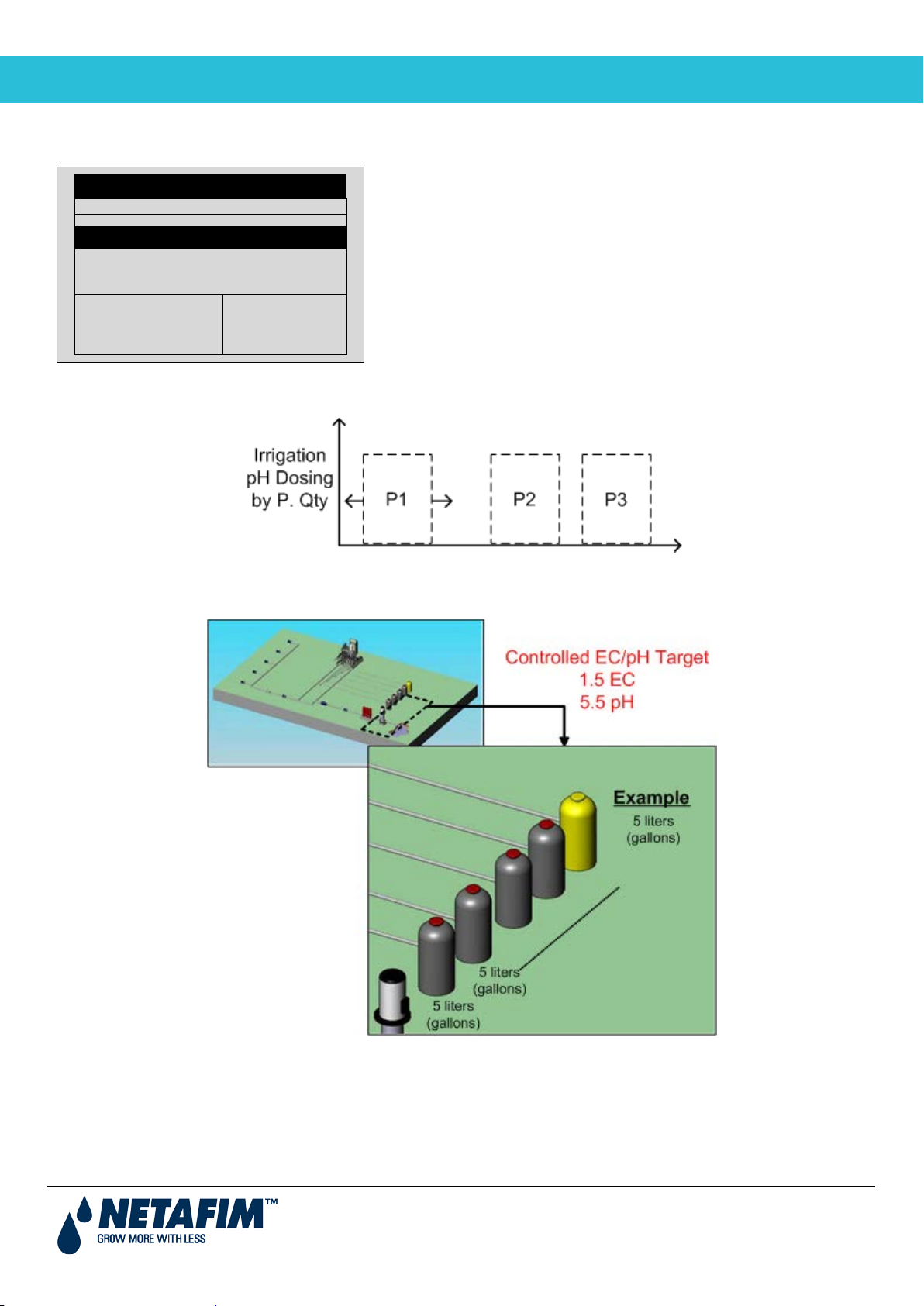
2.2.4.1 63BExample of Dosing by Quantity (Spread)
Using Quantity (Spread) is normally done in an open field. The following is an example of a Quantity (Spread)
configuration.
Program: 1
INJECTION PER DOSING CHANNEL
1
PASSIV
4.00
DOSING PROGRA M
2
PASSIV
5.00
3
ACID
2.00
---
---
---
---
---
Passive Method
PH Dosing Method
QTY.
P.QTY.
Ch. 1
Ch. 2
Spread Qty. = 4 liters
Spread Qty. = 5 liters
User Manual
Page 14
Page 15
NMC-PRO
PROGRAM MENU
2.2.4.2 64BExample of Controlled EC/pH Based on Proportional Quantity
Define dosing program: Nutrient amount and desired EC/pH levels
Program: 1
1
2
3
---
The following is an example of how to configure the controller so that the pH is maintained at a certain level.
DOSING PROGRA M
INJECTION PER DOSING CHANNEL
EC
5.00
Target EC
Target PH
EC Dosing Method
PH Dosing Method
EC
5.00
1.50
5.50
P.QTY
P.QTY
ACID
5.00
---
---
**Channel 3 (Acid channel): pH is controlled at 5.50. To keep pH levels on target, the Pulse width (meaning the
quantity in each pulse) fluctuates according to controller calculations.
3 liter
1m³
pH Target = 5.5
User Manual
Page 15
Page 16
NMC-PRO
PROGRAM MENU
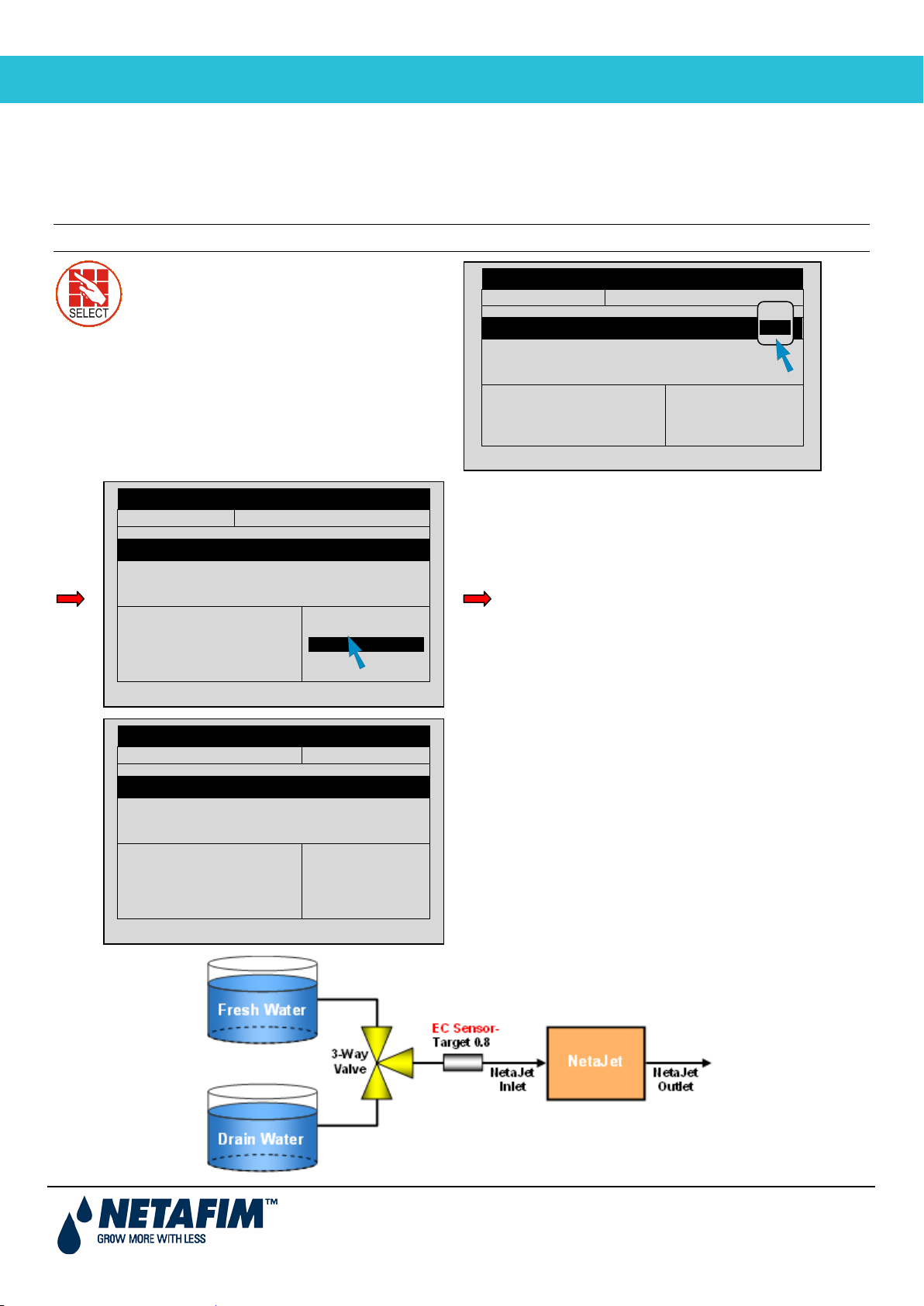
2.2.5 54BEC Pre-Control
EC Pre-Control ON (this enables
Program: 1
EC Pre-Control: ON
1
2
3
--Program: 1
EC Pre-Control:
1
2
3
---
Target EC
1.50
Program: 1
EC Pre-Control: ON
1
2
3
---
Target EC
1.50
Use this option in hydraulic pre-control systems in greenhouses. When collecting excess water from drains, the
grower can set an EC target before water goes through an irrigation system. This method reuses excess fertilizer and
water, recycling them for a second irrigation run.
Note: An EC Pre-Control valve relay must be defined by a technician at installation.
the control)
INJECTION PER DOSING CHANNEL
EC
2.00
Target EC
Target PH
EC Dosing Method
PH Dosing Method
DOSING PROGRA M
EC
ACID
5.00
3.00
1.50
5.50
P.QTY
P.QTY
OFF
ON
---
---
DOSING PROGRA M
INJECTION PER DOSING CHANNEL
EC
2.00
Target PH
Target EC Pre-Control
EC Dosing Method
PH Dosing Method
EC
5.00
ACID
3.00
5.50
-----
P.QTY
P.QTY
---
---
Define pre-controlled EC target
DOSING PROGRA M
INJECTION PER DOSING CHANNEL
EC
2.00
Target PH
Target EC Pre-Control
EC Dosing Method
PH Dosing Method
EC
5.00
ACID
3.00
5.50
0.80
P.QTY
P.QTY
---
---
User Manual
Page 16
Page 17
NMC-PRO
PROGRAM MENU
2.3 12BIrrigation Program
1. Irrigation
Select program
1. Program
DATE : 19-Apr-07 TIME : 16:12:32
Program: 4
Priority:
Const. 0%
Start Time
08:00 10:00
Day: 01/01
In the Irrigation Program screen, complete the irrigation setup.
.
In this screen define the following:
• Start time: This parameter defines the irrigation program time period. Each period begins at the defined time
and runs until the next defined time. Define up to six periods for each irrigation program. For example:
If you enter one time, the time period is 24 hours, starting from the time entered.
If you enter two times, the first period goes from first time defined until the second time. The second
period then starts and continues until the first time. For example in the screen below, the first period
starts at 8:00 and continues until 10:00. The second period begins at 10:00 and continues until 8:00
(the next day).
• Clock Start: This parameter defines the number of irrigation cycles within each time period. In the example
below, there are two cycles between 8:00 – 10:00 and three cycles from 10:00 – 8:00.
• Min. Time: The minimal amount of time between cycle starts
IRRIGATION PROGRAM
Clock Start
Min. Time
Valve #
Run Time #
Dosing Prog
2 3
01:00 01:00
001
1
1
Dose/Water 1 D
• Valve #: Select which irrigation valve(s) open(s) (refer to Setting Valve Sequence, page 18).
• Run Time #: Select the required Run Time Program (refer to Run Time Program, page 9).
• Dosing Prog: Select the required Dosing Program (refer to Dosing Progr am, page 11).
• Day: Type the current day/number of days in cycle (refer to Configur ing the Ir rigat ion Calendar, page 21).
• Dose/Water: For each day define the irrigation regime (refer to Configuring the Irrigation Calendar, page 21).
• Irrigation Adjustments: Along with irrigation programs based on time, NMC enables adjusting or running
irrigation based on the following:
Adjusting the Water Quantity Based on Weather Conditions, page 20
Irrigation Based on External Conditions, page 22
Irrigation Based on Radiation Sum, page 27Irrigation Based on VPD Sum , page 28
Introduction to the Influence Program, page 29
User Manual
Page 17
Page 18
NMC-PRO
PROGRAM MENU
2.3.1 Setting Valve Sequence
Example 2: Cycling Irrigation Program for Group of Two Valves
In this example, two valves operate simultaneously (valves operating together is a called a group). All other
DATE : 19-Apr-07 TIME : 16:12:32
Program: 4
Priority:
Const. 0%
Start Time
08:00
Day: 01/01
The following section provides examples on how to set the val ves’ sequence.
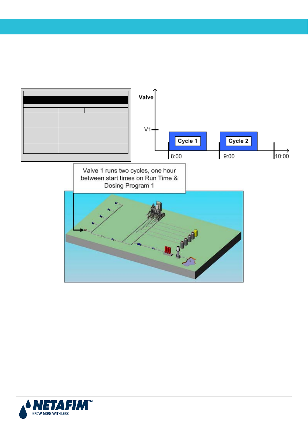
Example 1: Cycling Irrigation Program for One Valve
In the following example, Irrigation Program 4 begins running at 8:00 AM. There are two cycles, with one hour in
between each cycle. Irrigation is from one valve. Run Time program 1 and Dosing Program 1 are used.
IRRIGATION PROGRAM
Clock Start
Min. Time
Valve #
Run Time #
Dosing Prog
Dose/Water 1 D
2
01:00
001
1
1
specifications are the same as those found in Example 1.
Note: Valves in the same group must have the same run time.
User Manual
Page 18
Page 19

NMC-PRO
PROGRAM MENU
Example 3: Irrigation Program for a Group and Individual Valve
DATE : 19-Apr-07 TIME : 16:12:32
Program: 4
Priority:
Const. 0%
Start Time
08:00 10:30 12:30
Day: 01/03
1 2 3
DATE : 19-Apr-07 TIME : 16:12:32
IRRIGATION PROGRAM
Program: 4
Priority:
Const. 0%
Start Time
08:00
Day: 01/01
Clock Start
Min. Time
Valve #
Run Time #
Dosing Prog
Dose/Water 1 D
2
01:00
001 + 002
1 1
1 1
In this example, Valves 1 and 2 are designated as a group. Valve 3 is designated as an individual valve. There are
different/interchangeable delays (multiple start time) dividing the day into periods.
The first cycle’s (C1) run time begins at 8:00 (Valve 1 and 2). Valve 3 begins operating at its run time. In this example,
Valve 3 begins operating after Valve 1 and 2 finishes. This process is repeated once (C2), with a break of one hour
between cycle start times.
Cycle 3 (C3) begins at 10:30. In this cycle, there is a 30 minute break between cycles (C4). The process continues as
shown in the graph below.
Clock Start
Min. Time
Valve #
Run Time #
Dosing Prog
Dose/Water
IRRIGATION PROGRAM
2 2 2
01:00 00:30 01:00
001 + 002 003
1 1 2
1 1 2
D W D
User Manual
Page 19
Page 20

NMC-PRO
PROGRAM MENU
Start Time
Min. Time
08:00 10:30
01:00 00:30
Valve #
001+002 003
2.3.2 Adjusting the Water Quantity Based on Weather Conditions
The NMC Irrigation Pro enables you to manually increase or decrease the quantity of water on any given day.
Depending on the weather c ondit ions , you can change the quantity of water emitted from valves without changing the
program.
Example 4: Increasing Irrigation
In this example, water is supplemented by 20% to compensate for an increase in heat. If the regular run time is 10
minutes, the actual run time will be 12 minutes. All other specifications are the same as those found in Example 3.
Note: The change to the programs affects both Valves 1 and 2, and Valve 3.
Note: Dosing is not affected when using this function, only the quantity of water.
There are two options:
• Daily: Program adjustment is for one day only. Regular program resumes the following day.
• Const: Program adjustment continues until changed.
DATE : 19-Apr-07 TIME : 16:12:32
IRRIGATION PROGRAM
Program: 4 Priority: Daily 20%
Clock Start
2 2
Run Time #
Dosing Prog
Day: 01/01
Dose/Water
1 1 2
1 1 2
1 2 3
D W -
User Manual
Page 20
Page 21

NMC-PRO
PROGRAM MENU
Example 5: Decreasing Irrigation
1 2 3 4 5 6 7 X X X X
X
Irrigation by dosing or water
DATE : 19-Apr-07 TIME : 16:12:32
Program: 4
Priority:
Daily -10%
Valve #
001+002 003
Dose/Water
D -
DATE : 19-Apr-07 TIME : 16:12:32
Program: 4
Priority:
Daily 20%
Start Time
08:00 10:30
Day: 04/07
Dose/Water
1 2 3 4 5 6 7
D - D W D - D
In this example, irrigation is decreased by 10% to compensate for a decrease in heat. If the regular run time is 10
minutes, the actual run time is nine minutes.
IRRIGATION PROGRAM
Start Time
Clock Start
Min. Time
Run Time #
Dosing Prog
Day: 01/01
08:00 10:30
2 2
01:00 00:30
1 1 2
1 1 2
1
2.3.3 Configuring the Irrigation Calendar
NMC-Pro enables scheduling irrigation programs by:
• Daily calendar
• Irrigation by dosing or water
When setting up a schedule, configure the following:
• Day: X/Y
X represents the first day that the cycle begins. For example, if you want to define the first day of
the cycle as day 4, define X as 4.
Y represents the length of the cycle. If the length is 7 days, define Y as 7. You can schedule up
to 14 days.
• Dose/Water: For each day, define what the regime type for each day:
Dose: Water and dosing
Water: Water only
None: No irrigation
Clock Start
Min. Time
Valve #
Run Time #
Dosing Prog
IRRIGATION PROGRAM
2 2
01:00 00:30
001+002 003
1 1 2
1 1 2
AND
Select the daily calendar
User Manual
Page 21
Page 22

NMC-PRO
PROGRAM MENU
D - D W D - D
DATE : 19-Apr-07TIME : 16:12:32
IRRIGATION PROGRAM
Program: 4
Priority: --
Daily 20%
Start Time
08:00 10:30
Day: 04/07
1 2 3 4 5 6 7
Dose
In this example, the seven day cycle begins on the
fourth day (04/07). On the fourth day, the irrigation is
water only (no dosing).
1 2 3 4 5 6 7
Clock Start
Min. Time
Valve #
Run Time #
Dosing Prog
Dose/Water
2 2
01:00 00:30
001+002 003
Water
1 1
None
1 1
D - D W D - D
2.4 13BIrrigation Based on External Conditions
Irrigation can be controlled by input from dry contact or analog sensor triggers.
• If the Irrigation Program is active, these programs can only function after the Irrigation Program is completed.
• If the Irrigation Program is inactive, these programs can function during the defined time frame.
• In both cases, irrigation begins only when external conditions meet the user-defined requirements.
Irrigation programs can be controlled via dry contact input or analog sensors from peripheral equipment (for example,
filling a water tank according to level float switch). When using dry contacts or analog sensors, set the following:
• Time frame that the program can operation
• Which trigger input starts and stops irrigation
• The trigger type:
One Shot: Irrigation runs once
Multi Shot: Irrigation continues to run until a stop signal is received
Only If On: Used when there is one switch only. Irrigation continues as long as switch remains on
NMC Pro supports up to 15 extension programs defining which trigger initiates irrigation. In each program, the start
and stop trigger must be the same type (meaning both must be dry contact or analog sensor).
User Manual
Page 22
Page 23

NMC-PRO
PROGRAM MENU
To configure an irrigation program triggered by external condition:
1. Irrigation
Select dry contact to start and stop
DATE : 1-May-07 TIME : 10:12:09
Const.
1. Program
Start
Trigger
Stop
1
7
Dry Con 1
<NONE>
One Shot
One Shot
Dry Con
<NONE>
One Shot
1. Program
1
07:00
18:00
Dry Con 1
Start
Trigger
Stop
1
8
Dry Con 1
<NONE>
One
Shot
Dry Con 2
<NONE>
IRRIGATION PROGRAM
Program: 1 Priority: -- Cond. 1
Start Time
Clock Start
Contact
Min. Time
Max. Time
Valve #
Run Time #
Dosing Prog
07:00
1
ON
--:--
--:--
001
1
1
For Next Screen Press The DOWN Arrow
The following sections detail how to set up the dry contact and analog sensor triggers.
2.4.1 55BSetting the Dry Contacts
The following section details how to set dry contact to control irrigation.
4. Ext.
Condition
This is the
time frame
in which the
condition (if
true) can
operate
EXTERNAL CONDITION PROG RA M
#
2
3
4
5
6
7
8
From
hh:mm
--:--
--:--
--:--
--:--
--:--
--:--
--:--
08:00
-300
00:30
--:--
To
hh:mm
--:--
--:--
--:--
--:--
--:--
--:--
--:--
10:00
--
150
Daily
00:20
Cond.
--:--
Rad Sum
Start
Dry Cont.
<NONE>
<NONE>
<NONE>
<NONE>
<NONE>
<NONE>
<NONE>
1
----
--:-
-
--:-
-
Select trigger type
EXTERNAL CONDITION PROGRAM
#
Dry Cont.
2
<NONE>
3
<NONE>
4
<NONE>
5
<NONE>
6
<NONE>
external condition program.
Type
One Shot
One Shot
One Shot
One Shot
One Shot
Dry
Cont.
Multi Shot
2
<NONE>
<NONE>
<NONE>
<NONE>
EXTERNAL CONDITION PROG RA M
#
2
3
4
5
6
7
Dry Cont.
<NONE>
<NONE>
<NONE>
<NONE>
<NONE>
<NONE>
Type
Shot
One
Shot
One
Shot
One
Dry Cont.
<NONE>
<NONE>
<NONE>
<NONE>
<NONE>
<NONE>
User Manual
Page 23
Page 24

NMC-PRO
PROGRAM MENU
Num.
Sensor Type
Min Value
Max Value
3
ECh20
7
45
4
Netasense
7
45
Gen. Sensor
Temperature
Num.
Sensor Type
Min Value
Max Value
2
->
->
-> 3 ->
->
->
Example of Tank Filling:
Water Tank with Floats
2.4.2 56BConfiguring the Analog Sensors
The following section details how to configure analog sensors to control irrigation.
Note: In general, a technician performs steps 1 and 2 during installation. The user only begins from step 3.
1. In Setup > Analog Conversion Table:
a. Select the sensor type. Each sensor has default values assigned to it.
Netasense: 7 – 45
ECH20: 0 – 60
General Sensor: 0.2 - 10
b. If required, edit the values.
ANALOG CONVERSION TABLE
1
4
->
->
->
->
->
->
2. In Test > Analog Sensor, view the actual sensor values.
ANALOG CONVERSION TABLE
1 7 45
2 <NONE> 7 45
User Manual
Page 24
Page 25

NMC-PRO
PROGRAM MENU
c. Define The Trigger Type.
d. Under Stop An. Dry Con., define the input type.
3
Ana. Sen 2
Dry Con 14
---
4
Ana. Sen 3
<NONE>
---
6
Ana. Sen 5
<NONE>
---
7
Ana. Sen 6
<NONE>
---
8 <NONE>
---
3
One Shot
Dry Con 14
Multi Shot
4
One Shot
<NONE>
Only If On
5
One Shot
<NONE>
---
6
One Shot
<NONE>
---
7
One Shot
<NONE>
---
8
One Shot
<NONE>
---
3
Ana. Sen 2
13:00
Dry Con 1
4
Ana. Sen 3
--:--
<NONE>
6
Ana. Sen 5
--:--
<NONE>
7
Ana. Sen 6
--:--
<NONE>
8 --:--
<NONE>
2
11:00
12:00
Dry Con 1
5
--:--
--:--
<NONE>
6
--:--
--:--
<NONE>
7
--:--
--:--
<NONE>
8
--:--
--:--
<NONE>
ANALOG SENSOR
1
Netasense
11
3
Netasense
33
6
ECh20
25
8
ECh20
51
9
Temperature
21
No. Type Value
2 Netasense 22
4 Gen. Sensor 7
5 Gen. Sensor 3
7 ECh20 32
10 Temperature 21
3. In Program > Ext Condition, configure the External Condition Program for the analog sensors.
a. Enter the beginning and ending time for each
program
EXTERNAL CONDITION PROG RA M
# From
hh:mm
1 10:00 12:00 Ana. Sen 1
3 12:00 13:00 Dry Con 1
4 --:-- --:-- <NONE>
EXTERNAL CONDITION PROG RA M
# Trigger Type Stop An
1 Multi Shot Ana. Sen 2 --2 Multi Shot Dry Con 2 One Shot
To hh:mm Start An.
Dry Cont.
Dry Cont.
Oper.
to Start
b. Under Start An. Dry Cont., define the input type.
EXTERNAL CONDITION PROG RA M
# From
hh:mm
1 12:00 Ana. Sen 1
2 Ana. Sen 1 12:00 Dry Con 1
5 Ana. Sen 4 --:-- <NONE>
To
hh:mm
Start An.
Dry Cont.
EXTERNAL CONDITION PROGRAM
# Trigger Type Stop An
Dry Cont.
1 Ana. Sen 2 --2 Ana. Sen 1 Dry Con 2 ---
Oper.
to Start
5 Ana. Sen 4 <NONE> ---
User Manual
Page 25
Page 26

NMC-PRO
PROGRAM MENU
e. Under Oper. to Start, choose the required symbol. f. Under Oper. To Stop, choose the required symbol.
Symbol
Definition
---
No operation
=
The analog sensor function value is equal to the start/stop value. There is a ± 1%
#
Start
Oper.
Stop
1
25 = 20
3
---
---
---
4
---
---
---
6
---
---
---
7
---
---
---
#
Oper.
Start Value
Oper.
1 25
=
2
---
---
---
5 = ---
---
6 > ---
---
7
>=
---
---
#
Stop An
Oper.
Start
1
Ana. Sen 2 >
2
Dry Con 2
---
---
5
<NONE>
---
=
6
<NONE>
---
>
7
<NONE>
---
>=
EXTERNAL CONDITION PROG RA M
Dry Cont.
3 Dry Con 14 --- <
4 <NONE> --- <=
8 <NONE> ---
to Start
Value
g. Under Start Value, enter the required value to start
the analog sensor. Under Stop Value, entered the
required value to stop the analog sensor.
EXTERNAL CONDITION PROG RA M
Value
2 --- --- ---
5 --- --- ---
to Stop
Value
EXTERNAL CONDITION PROG RA M
to Start
3 < --- --4 <= --- ---
8 --- --- ---
to Stop
8 --- --- ---
In the examples given above, irrigation has been set to start when the analog input is greater than 25 and irrigation
stops when the input is 20.
Oper. to Start and Oper. to Stop require a logical operation. The following table defines these symbols:
<, <= The analog sensor function value is less than/less than or equal to the start/stop
value.
allowable deviation.
>, >= The analog sensor function value is greater than/greater than or equal to the
start/stop value.
User Manual
Page 26
Page 27

NMC-PRO
PROGRAM MENU
2.5 14BIrrigation Based on Radiation Sum
Valve #
001
DATE : 1-May-07 TIME : 10:12:09
Program: 1
Priority: --
Rad Sum
Start Time
07:00
08:00
10:00
Valve #
001
1. Program
NMC Pro enables setting an irrigation trigger based on a radiation sum limit (joul/cm² = energy).
When using this option, set the following:
• Start Time: Start Time is when the unit begins measuring radiation levels to implement the irr igat ion pr ogram.
• Clock Start: Number of cycles. 0 (zero) means that this program is disabled. 1 (one) means that this program
runs one time after time-based irrigation is completed. 2 (two) means that the program runs twice, and so on.
• Radiation Sum Limit: This parameter determines the minimal amount of accumulated radiation required for
irrigation to start.
• Minimum Time: When irrigation begins, NMC Pro erases the current radiation sum and restarts the count.
Minimum time is the minimal amount of time between irrigation starts, even if the radiation sum has reached
its limit.
• Maximum Time: This parameter determines the maximum amount of time between irrigation starts, even if
the sum limit has not been reached.
1. Irrigation
Clock Start
Rad Sum Li.
Min. Time
Max. Time
IRRIGATION PROGRAM
1
100
--:--
--:30
-300
00:30
--:--
--
Const.
150
Daily
00:20
Cond.
--:--
Rad Sum
1
----
--:-
-
--:-
-
Run Time #
Dosing Prog
DATE : 1-May-07 TIME : 10:12:09
Program: 1 Priority: -- Rad Sum
Start Time
Clock Start
Rad Sum Li.
Min. Time
Max. Time
Run Time #
Dosing Prog
1
1
For Next Screen Press The DOWN Arrow
IRRIGATION PROGRAM
07:00
1
100
--:--
--:30
1
1
For Next Screen Press The DOWN Arrow
08:00
-300
00:30
01:00
10:00-
150
00:20
01:00
16:00
--
----
--:--
--:--
User Manual
Page 27
Page 28

NMC-PRO
PROGRAM MENU
In the example below, between 8:00 – 10:00, the Radiation Sum Limit is 300; between 10:00 – 16:00 the limit is 150.
1. Irrigation
1. Program
DATE : 1-May-07 TIME : 10:12:09
Program: 1
Priority: --
VPD Sum
Start Time
07:00
08:00
10:00
DATE : 1-May-07 TIME : 10:12:09
Program: 1
Priority: --
VPD Sum
Max. Time
--:--
01:00
01:00
--:--
Valve #
001
Since during the afternoon hours there is a greater amount of sunlight, the user lowered the limit to ensure that they
receive sufficient amounts of irrigation.
2.6 15BIrrigation Based on VPD Sum
NMC Pro enables setting an irrigation trigger based on Vapor Pressure Deficit (kPa•min). The Vapor Pressure Deficit
(VPD) is a measurement which incorporates both the relative humidity (RH) and the temperature. When the VPD is
high, that means that the RH is low or the temperature is high. Irrigation begins when the VPD reaches the userdefined limit.
Irrigation based on VPD Sum can take place only during the VPD time frame. Refer to 6.1 SETUP > TIME & DATE to
define the start and end time for VPD Sum. Normally, this parameter is defined during installation.
Clock Start
Rad Sum Li.
Min. Time
Max. Time
Valve #
Run Time #
Dosing Prog
IRRIGATION PROGRAM
1
----
--:--
--:- 001
1
1
-30
00:30
--:--
Daily
Cond.
Rad Sum
--
VPD Sum
150
00:20
--:--
1
----
--:--
--:--
Start Time
Clock Start
VPD Sum Li.
Min. Time
Run Time #
Dosing Prog
For Next Screen Press The DOWN Arrow
IRRIGATION PROGRAM
07:00
1
----
--:--
1
1
08:00
-30
00:30
10:00
-15
00:20
16:00
--
----
--:--
• Start Time: Start Time is when the unit begins measuring and calculating VPD levels to implement the
irrigation program.
• Clock Start: Number of cycles. 0 (zero) means that this program is disabled. 1 (one) means that this program
runs one time after time-based irrigation is completed. 2 (two) means that the program runs twice, and so on.
User Manual
Page 28
Page 29

NMC-PRO
PROGRAM MENU
• VPD Sum Limit: This parameter determines the minimal (accumulated) VPD required for irrigation to start.
• Minimum Time: When irrigation begins, NMC Pro erases the current VPD sum and restarts the count.
Minimum time is the minimal amount of time between irrigation starts, even if the radiation sum has reached
its limit.
• Maximum Time: This parameter determines the maximum amount of time between irrigation starts, even if
the VPD limit has not been reached.
2.7 16BIntroduction to the Influence Program
Irrigation Pro enables adjusting irrigation settings according the following factors (labeled “Influences” on the screen):
• Solar radiation
• Amount of drainage
• Amount of fertilizer present in the drainage
• VPD
• Temperature
These Influences can adjust the following irrigation settings:
• EC
• Radiation Sum (RadS)
• Minimum Rest Time (MinT)
For example, a grower may want to increase the EC based on the Solar Radiation. Alternatively, he may want to
decrease the MinT based on the drainage.
2.8 17BUsing the Influences
• Set an Influence to increase or decrease the setting.
• Changes to the setting are in percentages (for example, a 10% increase in the EC level).
• Several Influences adjust the EC setting. The final adjustment amount is based on the sum total of the
different Influences.
• You enter up to three points for each Influence setting. Irrigation Pro automatically calculates the curve based
on these points.
• You can program up to 15 different programs (corresponding to the 15 irrigation programs)
• After configuring an Influence, you must enable it (under ACTIVE/SOURCE).
2.8.1 57BSetting the Influences
1. Go to Install > Device Layout .
2. Define relays as dosing channels, as required.
3. Go to Program > Irrigation.
4. Using the arrow keys, scroll down to Screen 2. The following screen appears.
User Manual
Page 29
Page 30

NMC-PRO
PROGRAM MENU
DATE: 2 –Feb-12 TIME 12:52-08
IRRIGATION PROGRAM
INFLUENCE
TABLE
ACTIVE/SOURCE
Radia./EC
NO
Drain/RadS
NO
Drain/MinT
NO
EC Drain/EC
NO
Program: 1 Priority: -- Const. 0%
VPD/EC
Temp/EC
Screen 2 of 2 – In order to view the
NO
NO
5. Set the required Influences to YES.
The following sections detail each Influence.
Note: The following sections include examples. These examples are not meant to be actual numbers used in
practice; they simply illustrate the operating principles. Consult with your local extension agent for actual
specifications.
2.8.2 Radiation Influence on Target EC
This function enables adjusting the EC based on solar radiation. Solar radiation increases the greenhouse
temperature. Adjust the EC according to your crops’ requirements.
To set the Radiation Influence:
1. In Installation > Analog Input , define a sensor as EC.
2. In Configuration > Dosing Channel Configuration, set React to EC.
3. In Configuration > Dosing Configuration > EC Control to Yes .
4. In Program > Irrigation, select Radia./EC.
5. Define the Radiation set points (w/m2).
6. Define the EC change in percentages.
7. Set ACTIVE/SOURCE to Yes.
8. Press Menu and confirm changes.
9. In Program > Dosing Program, set:
a. the Target EC
b. EC Dosing Method to Qty
User Manual
Page 30
Page 31

NMC-PRO
PROGRAM MENU
Example: As sunlight increases, a crop needs lower EC levels. The following screen illustrates increasing in the EC
DATE: 2 –Feb-12 TIME 12:52-08
Program: 1
Priority: --
Const. 0%
INFLUENCE
TABLE
ACTIVE/SOURCE
Drain/RadS
(w/m2)
(%)
Drain/MinT
200
0
VPD/EC
800
-20
Temp/EC
Screen 2 of 2 – In order to view the
based on radiation. Since Irrigation Pro calculates the decrease in EC proportionally, there will be a 15% decrease
when the radiation reaches 600 w/m2.
IRRIGATION PROGRAM
Radia./EC
Radia. EC
EC Drain/EC
400 -10
2.8.3 58BDrainage Influence on Target Radiation Sum
Irrigation can be triggered by the Radiation Sum (Rad Sum). This Influence enables adjusting the Rad Sum based on
the amount of drainage.
To set the Drainage Influence on Rad Sum:
1. In Program > Irrigation, set Contr. to Rad Sum.
2. In Installation > Digital Input , define which digital input is the drain meter.
Note: The drainage must be defined correctly! You can check the drainage meter status using Hot key 9.
3. In Configuration > Valve Configuration define which valve number corresponds to which drainage meter.
4. In Configuration > Drainage Configuration, define the drainage meter’s Ratio Liter/Pulse.
User Manual
Page 31
Page 32

NMC-PRO
PROGRAM MENU
5. In Program > Irrigation, select Drain/RadS.
DATE: 2 –Feb-12 TIME 12:52-08
Program: 1
Priority: --
Const. 0%
INFLUENCE
TABLE
ACTIVE/SOURCE
Drain/RadS
(%)
(%)
Drain/MinT
20
-10
VPD/EC
55
30
Temp/EC
Screen 2 of 2 – In order to view the
a. Define the Drainage percentage set points.
b. Define the RadS percentage set points.
6. Set ACTIVE/SOURCE to Yes.
7. Press Menu and confirm changes.
Example: A user set irrigation to be triggered by the radiation sum. As can be seen, the increases are not
proportional.
IRRIGATION PROGRAM
Radia./EC
DRAIN% RadS
EC Drain/EC
30 10
2.8.4 59BDrain Influence on Minimum Time
Minimum time defines the minimum break between irrigations. Even if the Rad/VPD sum limit / condition limit has
been reached irrigation does not take place until this time has passed. This function enables adjusting the Minimum
Time based on the drainage.
To set the Drainage Influence on the Minimum Time:
1. In Installation > Digital Input , def ine which digital input is the drain meter.
Note: The drainage must be defined correctly! You can check the drainage meter status using Hot key 9.
2. In Configuration > Valve Configuration define which va lv e num ber corresponds to which drainage meter.
3. In Configuration > Drainage Configuration, define the drainage meter’s Ratio Liter/Pulse.
4. In Program > Irrigation, select Drain/MinT.
a. Define the Drainage percentage set points.
User Manual
Page 32
Page 33

NMC-PRO
PROGRAM MENU
b. Define the MinT percentage set points.
DATE: 2 –Feb-12 TIME 12: 52-08
Radia./EC
DRAIN%
MinT
Drain/RadS
(%)
(%)
Drain/MinT
20
-25
Temp/EC
5. Set ACTIVE/SOURCE to Yes.
6. Press Menu and confirm changes.
Example: When drainage is low, a user wants to decrease the Minimum Time. He sets 20% drainage to a MinT of
-25%. As drainage increases, the time between irrigation increases. In this scenario, if the MinT is set to 60 minutes,
40% drainage adjusts the time to 75 minutes.
IRRIGATION PROGRAM
Program: 1 Priority: -- Const. 0%
INFLUENCE TABLE ACTIVE/SOURCE
EC Drain/EC
VPD/EC
40 25
2.8.5 60BDrai na ge E C Level Inf luence on Target EC
If you have installed an EC sensor in the drainage, you can adjust the Target EC level based on the drainage EC
level. This can be used, for example, to lower the EC input if EC levels in the drainage are above specifications.
To set the EC Drainage Influence on the EC:
User Manual
Page 33
Page 34

NMC-PRO
PROGRAM MENU
1. In Installation > Analog Input:
DATE: 2 –Feb-12 TIME 12:52-08
Program: 1
Priority: --
Const. 0%
Radia./EC
EC Drain / EC
Drain/MinT
1
0
EC Drain/EC
2
-10
Temp/EC
Screen 2 of 2 – In order to view the
a. Define a sensor as EC.
b. Define a sensor as EC drain.
2. In Installation > Digital Input define which digital input is the drain meter.
Note: The drainage must be defined correctly! You can check the drainage meter status using Hot Key 9.
3. In Configuration > Valve Configura tio n def ine which va lv e num ber corr es ponds t o which dra in age m eter.
4. In Configuration > Dosing Channel Configuration set React to EC.
5. In Configuration > Dosing Configuration > EC Control to Yes .
6. In Configuration > Drainage Configuration, define the drainage meter’s Ratio Liter/Pulse.
7. In Program > Irrigation, select EC Drain/EC.
a. Define the EC Drain percentage set points.
b. Define the EC percentage set points.
8. Set ACTIVE/SOURCE to Yes.
9. Press Menu and confirm changes.
10. In Program > Dosing Program set the Target EC.
Note: You can disable this function by disabling EC Control (Configuration > Dosing Configuration).
IRRIGATION PROGRAM
INFLUENCE TABLE ACTIVE/SOURCE
Drain/RadS
VPD/EC
mS/cm (%)
3 -20
Example: A user wants to maintain an EC level of 1.5. To this end, he measures the drainage EC. When the drainage
EC falls below 1.5, he increases the EC input. As it rises above 1.5 ms/cm, he decreases the input.
User Manual
Page 34
Page 35

NMC-PRO
PROGRAM MENU
2.8.6 61BVPD Infl ue nc e on Target EC
You can adjust the EC based on the VPD Sum (air temperature and humidity). As the VPD rises or falls, the program
can increase or decrease the EC level according to your requirements.
1. In Installation > Analog Input define:
a. a sensor as EC.
b. an air temperature sensor.
c. a humidity sensor.
Note: You can verify the EC status using Hot Key Screen, the temperature and humidity sensors status using Hot
Key Screen 6.
2. In Setup > VPD Sensor Setup, enable VPD Temperature and VPD Humidity sensors.
3. In Configuration > Dosing Channel Configuration set React to EC.
4. In Configuration > Dosing Configuration > EC Control, set EC Control to Yes.
5. In Program > Irrigation, select VPD/EC.
a. Define the VPD sum points.
b. Define the EC percentage set points.
6. Set ACTIVE/SOURCE to Yes.
7. In Program > Dosing Program:
a. Set the Target EC.
b. Set EC Dosing Method to Qty.
User Manual
Page 35
Page 36

NMC-PRO
PROGRAM MENU
Example: A grower wants to lower the EC as the kPa decreases. He sets this screen to reduce the increase in EC to
DATE: 2 –Feb-12 TIME 12:52-08
Program: 1
Priority: --
NO
0%
INFLUENCE
TABLE
OUT temp
Drain/RadS
Temp 3
Drain/MinT
Temp 4
VPD/EC
NO
Temp/EC
NO
DATE: 2 –Feb-12 TIME 12:52-08
INFLUENCE
TABLE
ACTIVE/SOURCE
Radia./EC
VPD
EC
EC Drain/EC
10
4
VPD/EC
5
2
Temp/EC
Screen 2 of 2 – In order to view the
match the decreasing VPD levels.
IRRIGATION PROGRAM
Program: 1 Priority: -- Const. 0%
Drain/RadS
Drain/MinT
(kPa) (%)
15 7
2.8.7 62BTemperature Influence on Target EC
You can adjust the EC based on the air temperature. As the temperature rises or falls, the program can increase or
decrease the EC level according to your requirements.
1. In Installation > Analog Input define:
a. a sensor as EC
b. an air temperature sensor
Note: You can verify the EC status using Hot Key Screen 4, the temperature sensor status using Hot Key
Screen 6.
2. In Configuration > Dosing Channel Configuration set React to EC.
3. In Configuration > Dosing Configuration > EC Control, set EC Control to Yes.
4. In Program > Irrigation, select Temp/EC.
a. Define the Temperature sum points.
b. Define the EC percentage set points.
5. Set ACTIVE/SOURCE, select the temperature sensor number.
IRRIGATION PROGRAM
Temp 1
Radia./EC
EC Drain/EC
Screen 2 of 2 – In order to view the
Temp 2
N/A
6. In Program > Dosing Program:
a. set the Target EC.
b. set EC Dosing Method to Qty.
Example: A grower’s flower crop requires higher EC levels when the temperature goes above room temperature 22°
C). Using this screen, he can adjust the levels accordingly.
User Manual
Page 36
Page 37

NMC-PRO
PROGRAM MENU
5. Agitator
Define On/Off time during dosing
DATE: 2 –Feb-12 TIME 12:52-08
IRRIGATION PROGRAM
INFLUENCE
PRIORITY
ACTIVE/SOURCE
Radia./EC
Temp
EC
Drain/RadS
(°C/F))
(%)
Drain/MinT
25
2
EC Drain/EC
27
5
Screen 2 of 2 – In order to view the
1. Program
mm:ss
mm:ss
Dosing Active
Operation Mode
Parallel
On
Off
Dosing Active
01:00
05:00
mm:ss
mm:ss
Dosing Active
01:00
05:00
Operation Mode
Serial
Parallel
Program: 1 Priority: -- Const. 0%
VPD/EC
Temp/EC
30 7
TEMP1
2.9 18BAgitator
Use this screen to operate fertilizer tanks equipped with mixing devices.
and when system is idle
On
Dosing Not
Active
Dosing Not Active
Operation Mode Parallel
AGITATOR
--:--
--:--
AGITATOR
mm:ss
05:00
Serial
Off
--:--
--:--
mm:ss
60:00
• Select Parallel to operate
more than one agitator
simultaneously
• Select Serial if not enough
power to operate more than
one agitator at a time
AGITATOR
On
Off
Dosing Not Active
05:00
60:00
User Manual
Page 37
Page 38

NMC-PRO
PROGRAM MENU
2.10
19B
6. Selector
20B
7. Filter
1. Program
1. Program
Dosing Prog.
Time Between Flushing (hh:mm)
02:00
Water Fill Up (min)
1
Selector
Use this screen to operate more than one fertilizer tank (containing different fertilizers) attached to a single dosing
channel. The program enables taking fertilizer from different tanks (according to the dosing program).
2.11
Filter Flushing
Use this screen to program filter flushing during irrigation.
Flushing
1
2
3
4
5
6
7
8
9
Flushing Time (mm:ss)
Delay Between Filters (mm:ss)
Delta Pressure (Digital)
Delta Pressure Valve (bar)
Delay Delta Pressure (mm:ss)
Delta P ressure Reiteration
Dwell Time Main (mm:ss)
FILTER FLUSHING PROGRAM
SELECTOR
S1 S2
00:10
00:05
YES
0.5
00:06
3
00:10
Item Description
Time Between Flushing
Flush Time Flush time per filter.
Delay Between Filters Set delay between the flushing of each filter (to bui ld up pressur e).
Note: Filter flush process can start only after main water line is full. The default time is one minute; see Menu 3.3.
ALARM DEFINITION
Water Leak (m3)
Water Leak Period (hh:mm)
Identify Leak-Subtr. Meter?
Dosing Channel Leak Delay(s)
Dosing Channel Leak (Pulse)
Dosing Flow Difference (%)
Missing Pulses For No Flow
Stop System Cons. Flow Alarm s
# of Irrig. Without Drainage
1.000
00:30
NO
3
10
25
10
-3
Note: See graph on next page for further information on these fields.
Flush occurs after the accumulated irrigation time (between all valves). Break
time between irrigation are not included. Only one filter is cleaned at a time.
Delta Pressure
Set flush by pressure sensor. Pressure at filter inlet/outlet, if there is a significant
difference, a filter may be blocked.
User Manual
Page 38
Page 39

NMC-PRO
PROGRAM MENU
Item Description
Delta Pressure Value (sensor) If there is a differential, (DP signal or Analog DP value), a flush is needed.
Delta Pressure Delay Set delay to verify if there is a definite blockage.
Delta Pressure Reiteration
Dwell Time Main
Set to give signal after XX flushes. If Delta Pressure still indicates a blockage, an
alarm will be raised.
Open main filter valve before flush to balance pressure for a reliable flushing
process.
User Manual
Page 39
Page 40

NMC-PRO
PROGRAM MENU
User Manual
Page 40
Page 41

NMC-PRO
PROGRAM MENU
2.12
21B
8. Cooling
Set On/Off time and select sensors
Temp. Sens. 1
Hum. Sens. 1
+1 of each sensor: uses average of both
Dynamic cooling: 2 temp. threshold, same Hum
On time is set.
1. Program
Cooling
This screen sets a cooling program for cooling/humidification process in greenhouses. This program operates
according to temperature, humidity or time (to reduce temperature, increase humidity.)
Program: 1 Status: Cooling
Below RH On Off
1
2
Cool# 1 2 - - - - - - - -
Temp. Sens.: 1 -- Hum. Sens.: 1 --
Program: 1 Status: Cooling
From To Above t°
1
2
Cool# 1 2 - - - - - - - -
Temp. Sens.: 1 2-- Hum. Sens.: 1 2
Program: 1 Status: Cooling
Below RH On Off
1
2
Cool# 1 2 - - - - - - - Temp. Sens.: 1 2-- Hum. Sens.: 1 2
COOLING/HUMIDIFICATION PROGRAM
80
---
COOLING/HUMIDIFICATION PROGRAM
80
80
COOLING/HUMIDIFICATION PROGRAM
80
80
00:00:10
--:--:--
16:00
16:00
00:00:10
00:00:10
00:00:10
--:--:--
25.0
35.0
00:00:10
00:00:10
OR
COOLING/HUMIDIFICATION PROGRAM
Program: 1 Status: Cooling
Below RH On Off
1
2
Cool# 1 2 - - - - - - - -
Temp. Sens.: 1 2 Hum. Sens.: 1 2
80
---
00:00:10
--:--:--
00:00:10
--:--:--
COOLING/HUMIDIFICATION PROGRAM
Program: 1 Status: Cooling
To Above t° Below RH
1
2
Cool# 1 2 - - - - - - - -
Temp. Sens.: 1 2-- Hum. Sens.: 1 2
16:00
16:00
25.0
35.0
80
80
Off time can be controlled according to temp.
High temp.= less off time
Low temp.= more off time
User Manual
Page 41
Page 42

NMC-PRO
PROGRAM MENU
2.13
22B
9. Misting
23B
10. Water
1. Program
1. Program
Misting
Use this screen to control misting in the greenhouse using a timer.
# No. Start
Define Start/End time
Define Misting On/Off
time
1
2
3
4
5
6
7
8
9
1
--
--
--
--
--
--
--
--
MISTING PROGRAM
hh:mm
08:00
--:--
--:--
--:--
--:--
--:--
--:--
--:--
--:--
End
hh:mm
16:00
--:--
--:--
--:--
--:--
--:--
--:--
--:--
--:--
On
hh:mm:ss
00:00:10
--:--:--
--:--:--
--:--:--
--:--:--
--:--:--
--:--:--
--:--:--
--:--:--
Off
hh:mm:ss
00:00:05
--:--:--
--:--:--
--:--:--
--:--:--
--:--:--
--:--:--
--:--:--
--:--:--
2.14
Water Heating
Use this screen to heat water in cold areas/seasons.
Heating
Define Start/End time
Define Water Temp. ±
Difference (dead band)
to stop
Define sensors
WATER HEATING
From Time
To Time
Water Temperature
Difference
Temp. Sensor #1
Temp. Sensor #2
08:00
16:00
20.0
2.0
1
2
User Manual
Page 42
Page 43

NMC-PRO
MANUAL MENU
3 2BMANUAL MENU
1. Irrigation pause
To resume, reverse steps above and select NO
2. Start/Stop
Select Program
Yes
To resume, reverse steps above and select NO
Program:
1
2. Manual
YES
2. Manual
SET
ACTUAL
LEFT
CYCLE
0
0
0
STATUS
ACTIVE
PROGRAM: PAUSE
This menu enables manual control over various functions.
• System Pause, page 43
• Start/Stop Program, page 43
• Start/Stop Valve, page 44
• Manual Filter Flush, page 45
3.1 24BSystem Pause
Use this function to manually pause the system during an irrigation program; for example if you need to calibrate the
EC/pH or fix the pipes.
WATER
FLOW
EC
Ph
15:38:16
VALVE: 1 25-Apr-07
Pause Irrigation? YES
ACTIVE IRRIGATION
00:15:00
100.000
1.5
5.5
IRRIGATION PAUSE
00:01:00
0.000
4.5
3.3
00:14:01
IRRIGATION
DOSING
3.2 25BStart/Stop Program
IRRIGATION PAUSE
Pause Irrigation? YES
NO
YES
Menu
START/STOP PROGR AM
Program
User Manual
Page 43
Page 44

NMC-PRO
MANUAL MENU
Note: Start one cycle only
3. Start/Stop
Select Valve and corresponding Run
Menu
Yes
To resume, reverse steps above and
Valve
2
2. Manual
#
Method
Water
Before
After
1
TIME
00:10:00
00:00:00
00:00:00
Program: 1
1
2
3
4
5
DATE : 1-May-07 TIME : 10:12:09
Program: 1
Priority: -
Rad Sum
from Program 1.
IRRIGATION PROGRAM
Start Time
Clock Start
Rad Sum Li.
Min. Time
Max. Time
Valve #
Run Time #
Dosing Prog
For Next Screen Press The DOWN Arrow
3.3 26BStart/Stop Valve
Use this screen to manually start/stop a valve.
START/STOP VALVE
Run Time #
Dosing Program
1
1
Valve
07:00
1
----
--:--
--:- 001
1
1
08:00
-300
00:30
01:00
Time/Dosing program
10:00
-150
00:20
01:00
select NO
13:00
-300
00:30
01:00
WATER RUN TIME PROGRAM
2
QTY.
3
QTY.
4
QTY.
5
QTY.
6
QTY.
7
START/STOP VALVE
Valve
Run Time #
Dosing Program
2
1
1
QTY.
8
QTY.
9
QTY.
10
QTY.
INJECTION PER DOSING CHANNEL
EC
5.00
Target EC
Target PH
EC Dosing Method
PH Dosing Method
0.000
0.000
0.000
0.000
0.000
0.000
0.000
0.000
0.000
DOSING PROGRA M
EC
5.00
0.000
0.000
0.000
0.000
0.000
0.000
0.000
0.000
0.000
EC
5.00
1.60
5.50
P.QTY
P.QTY
EC
5.00
0.000
0.000
0.000
0.000
0.000
0.000
0.000
0.000
0.000
ACID
3.00
Run Time Program
(1)
Dosing Program (1)
User Manual
Page 44
Page 45

NMC-PRO
MANUAL MENU
3.4 27BManual Filter Flush
4. Filter Flush
Select filters (usually all)
Yes
Menu
Hot Screen 5 to view
Which Filter
<None>
<None>
2. Manual
Flush Status
ON
Water Fill Up (min)
1
Use this screen to activate m anual filter flush. Us this function only when the system is irrigating.
MANUAL FILTER FLUSHING
All Filters
Filter 01
Filter 02
MANUAL FILTER FLUSHING
Which Filter to Flush? All Filters
flushing status
Item
Time To Nest Flush
Delta Pressure (Digital)
Flushing Filter No.
Remaining Filters Qty.
Flush Time
Current Delta Pressure
Main Filter Delay
FILTER FLUSHING STATUS
--:--:-OFF
1
1
00:07
---00:00:00
Note: "All Filters" means all filters; however one only one filter is flushed at a time.
Note: Filter flush process can start only after main water line is full. Default time is one minute as shown in picture
below (see Menu 3.3).
ALARM DEFINITION
Water Leak (m3)
Water Leak Period (hh:mm)
Identify Leak-Subtr. Meter?
Dosing Channel Leak Delay(s)
Dosing Channel Leak (Pulse)
Dosing Flow Difference (%)
Missing Pulses For No Flow
Stop System Cons.Flow Alarms
# of Irrig. Without Drainage
1.000
00:30
NO
3
10
25
10
-3
User Manual
Page 45
Page 46

NMC-PRO
ALARM MENU
4 3BALARM MENU
1. Alarm Reset
Option A: Reset manually
Option B: Automatic reset to check itself every so
Reset Now?
No
1
High Flow Valve #1
25/Apr
15:49
Reset Now?
No
No.
Message
Date
Time
1
High Flow Valve #1
25/Apr
15:49
3. Alarm
Reset Now?
No
24 h
Reset Now?
No
No.
Message
Date
Time
NO
The Alarm Menu is used to control the NMC’s alarm functions.
• Reset, page 46
• Alarm History, page 47
• Alarm Definition, page 47
• Alarm Setting, page 49
• EC/pH Alarm Definition, page 49
• EC/pH Alarm Setting, page 49
• Radio System Alarm Definition, page 50
• Radio System Alarm View, page 50
• SMS Subscription, page 51
4.1 28BReset
Use this function to reset the alarms in case of high flow, low flow, water leak, fertilizer leak, and so forth. Alarms can
be reset manually or manually.
ALARM RESET
Period Of Automatic Reset
Complete Irrig. On Reset?
ACTIVE ALARMS
No. Message Date Time
often as desired:
Select how often system should reset itself
24 h
YES
Period Of Automatic Reset
Complete Irrig. On Reset?
ALARM RESET
ACTIVE ALARMS
NO
YES
24 h
YES
Yes
Period Of Automatic Reset
Complete Irrig. On Reset?
No. Message Date Time
ALARM RESET
ACTIVE ALARMS
12 h
6 h
4 h
3 h
2 h
1 h
None
24 h
YES
"Complete Irrig. On Reset?" Select Yes or No
ALARM RESET
Period Of Automatic Reset
Complete Irrig. On Reset?
ACTIVE ALARMS
YES
24 h
YES
User Manual
Page 46
Page 47

NMC-PRO
ALARM MENU
4.2 29BAlarm History
2. History
3. Alarm
Define trigger: deviation from target pressure, flow…
3. Alarm
Water Fill Up (min)
1
Dosing Channel Leak Delay(s)
3
3. Alarm
112
EC Low Valve # 1
25/Apr
13:43
This is a read-only screen that displays the alarm history.
Note: The system logs up to 250 alarms.
No. Message Date Time
113
114
115
116
117
118
119
120
4.3 30BAlarm Definition
Use this function to define the system alarm thresholds.
Note: EC/pH thresholds are defined inEC/pH Alarm Definition, page 49.
Definition
ALARM DEFINITION
ALARM HISTORY
EC Low Valve # 1
High Flow Valve # 4
Emergency pH Low
Emergency EC High
High Flow Valve # 1
High Flow Valve # 1
High Flow Valve # 4
High Flow Valve # 1
ALARM DEFINITION
25/Apr
25/Apr
25/Apr
25/Apr
25/Apr
25/Apr
25/Apr
25/Apr
13:44
14:26
14:44
15:46
15:49
15:52
15:53
15:54
Water Leak (m3)
Water Leak Period (hh:mm)
Identify Leak-Subtr. Meter?
Dosing Channel Leak Delay(s)
Dosing Channel Leak (Pulse)
Dosing Flow Difference (%)
Missing Pulses For No Flow
Stop System Cons. Flow Alarm s
# of Irrig. Without Drainage
Low Pressure Alarm (bar)
No. Of Short Circ
. To Pause
1.000
00:30
NO
3
10
25
10
-3
2.5
3
Item Description
Water Fill Up (min)
Time of filling the main irrigation line. In that time, the system will ignore high flow alarm
and won't implement a filter flushing process.
Water Leak (m3 or Gal) Quantity of water leaking while the system is in idle.
Water Leak Period
(hh:mm)
Identify Leak-Subtr.
Meter?
Dosing Channel Leak
Delay (s)
Dosing Channel Leak
(Pulse)
Time frame to measure the water leak quantity
Example: 1m3 leaks in less than 30 minutes
This setting relevant only when working in "Water source" method. User can ignore or
identify a water leak.
Delay between switching off a dosing channel and generating dosing leak alarm.
Number of pulses (by dosing meter) during the delay above to generate an alarm.
Example: 10 pulses in 3 seconds generate an alarm.
Dosing Channel Leak (Pulse)
Dosing Flow Difference (%)
Missing Pulses For No Flow
Stop System Cons. Flow Alarm s
# of Irrig. Without Drainage
Low Pressure Alarm (bar)
No. Of Shor Cir. To Pause
Short Output Level (60-350)
Short O. Level EXP1 (60-350)
Short O. Level EXP2 (60-350)
Short O. Level EXP3 (60-350)
10
25
10
3
3
2.5
3
300
300
300
300
User Manual
Page 47
Page 48

NMC-PRO
ALARM MENU
Dosing Flow Difference
Dosing Channel Leak Delay(s)
3
Water Fill Up (min)
1
(%)
Difference between calculated and measured dosing channel flow. Example: Dosing
Channel 1 defined by technician as 100 liter/hour, but if the system measured less than
75 liter/hour or more than 125 liter/hour, an alarm will be generated.
ALARM DEFINITION
Water Leak (m3)
Water Leak Period (hh:mm)
Identify Leak-Subtr. Meter?
Dosing Channel Leak Delay(s)
Dosing Channel Leak (Pulse)
Dosing Flow Difference (%)
Missing Pulses For No Flow
Stop System Cons. Flow Alarm s
# of Irrig. Without Drainage
Low Pressure Alarm (bar)
No. Of Short Circ. To Pause
Table continued…
Item Description
Missing Pulses For No
Flow
Stop System
Consecutive Flow
Alarms
# of Irrigations Without
Drainage
Number of missing pulses before the system will generate a No Flow alarm. The system
calculates the expected time between pulses of water meter and if a certain time elapsed
without receiving the desired number of pulses, then generate an alarm.
Number of consecutive flow alarms of the same type (high flow, low flow etc’) but
different valves before the system is stopped. Example: High flow at valve 1 ->High flow
at valve 2->High flow at valve 3 = 3 consecutive High flow, then system stops.
Number of irrigations given without measuring drainage, above which an alarm will be
generated. Common reasons: Irrigation quantity is too small so there is not enough
drain, or drain measurement malfunction because of technical problem.
1.000
00:30
NO
3
10
25
10
-3
2.5
3
Dosing Channel Leak (Pulse)
Dosing Flow Difference (%)
Missing Pulses For No Flow
Stop System Cons. Flow Alarm s
# of Irrig. Without Drainage
Low Pressure Alarm (bar)
No. Of Shor Cir. To Pause
Short Output Level (60-350)
Short O. Level EXP1 (60-350)
Short O. Level EXP2 (60-350)
Short O. Level EXP3 (60-350)
ALARM DEFINITION
10
25
10
3
3
2.5
3
300
300
300
300
Low Pressure Alarm
(bar/psi)
Num. Of Short Circ. To
Pause
Short Output Level (60-
350)
Short O. Level EXT1
(60 – 350)
Short O. Level EXT2
(60 – 350)
Short O. Level EXT3
(60 – 350)
Minimum system pressure before generate an alarm.
Number of short circuit (in field device) alarms measured before the system is paused.
Define the A/D threshold value to be considered as a short circuit (For technician use
only).
Define the A/D threshold value to be considered as a short circuit for Extension box no. 1
(For technician use only)
Define the A/D threshold value to be considered as a short circuit for Extension box no. 2
(For technician use only)
Define the A/D threshold value to be considered as a short circuit for Extension box no. 3
(For technician use only)
User Manual
Page 48
Page 49

NMC-PRO
ALARM MENU
4.4 31BAlarm Setting
Define alarm action: automatically stop or
Delta Low: Maximum differences
6. EC/pH Alarm
3. Alarm
Delta EC Low
0.5
3. Alarm
High Flow
CONT.
STOP
01:00
NO
3. Alarm
Irr.
Dose
Delay
Alarm
EC High/Fail
STOP
STOP
01:00
YES
Use this function to define what actions are taken in the event of an alarm.
Note: EC/pH settings are defined in EC/pH Alarm Setting, page 49.
4. Alarm
Setting
Description
ALARM SETTING
Irr. Dose Delay
mm:ss
Alarm
Active
continue.
Delay before generating alarm.
Alarm output activation: YES/NO (siren,
light).
4.5 32BEC/pH Alarm Definition
Use this function to define the EC/pH alarm thresholds.
5. EC/pH Alarm
Definition
below EC, pH and EC Pre-Control targets.
Delta High: Maximum difference a bove EC, pH
and EC Pre-Control targets.
Emergency: Critical values of High EC and Low
pH that stop the system after 1min.
Low Flow
No Flow
D. Ch. Leak
D. Ch. Fault
Ext. Pause
D. Boos.Prot.
Low Pressure
R.U. Error
Host Error
Delta EC High
Delta pH Low
Delta pH High
Delta EC-Pre Control Low
Delta EC-Pre Control High
Emergency EC High (1 Min.Dly)
Emergency pH Low (1 Min.Dly)
STOP
STOP
STOP
STOP
PAUSE
CONT.
STOP
STOP
STOP
EC/pH ALARM DEFINITION
STOP
STOP
STOP
STOP
IRRIG.
STOP
STOP
STOP
STOP
01:00
---30:00
01:00
00:30
01:00
01:00
01:00
01:00
YES
YES
YES
YES
YES
YES
YES
YES
YES
0.5
0.5
0.5
0.5
0.5
5.0
2.0
4.6 33BEC/pH Alarm Setting
Use this function to set the EC/pH alarm and action definitions in the event of an EC/pH alarm.
Define EC/pH a larm action: automatic ally stop or
continue.
Delay before generating alarm.
Alarm output activation: YES/NO (siren, light).
Setting
Description
EC Low
pH High
pH Low/Fail
EC-P. Hi/Fail
EC-Pre. Low
E. Tank Fresh
E. Tank Drain
EC Sen. Dif.
pH Sen Dif.
EC/pH ALARM SETTING
mm:ss
STOP
STOP
STOP
STOP
STOP
STOP
STOP
STOP
STOP
STOP
STOP
STOP
STOP
STOP
STOP
STOP
STOP
STOP
01:00
01:00
01:00
01:00
01:00
01:00
01:00
01:00
01:00
Active
YES
YES
YES
YES
YES
YES
YES
YES
YES
User Manual
Page 49
Page 50

NMC-PRO
ALARM MENU
3. Alarm
4.7 34BRadio System Alarm Definition
7. Radio Sys Alarm
8. Radio Sys Alarm
Vin
HOST
0128
OK
-
-
3. Alarm
Delay
Active
Inform
RTU
UNIT # CARD # INPUT/OUTPUT#
Use this function to define Radio Systems alarm activity and notification.
IMPORTANT: For the Radio System to work properly, you MUST define in the 6.2 SYSTEM SETUP menu –
Remote Unit type parameter SN/RF Net.
RADIO SYS. ALARM DEFINITION
Definition
Alarm Type
Vbatt failure
Vbatt low
Vbatt warn
Cap failure
Card failure
I/O Open
I/O Shor
HOST
Over current
mm:ss
00:00
00:00
00:00
00:00
00:00
00:00
00:00
00:00
YES
NO
NO
NO
NO
NO
NO
NO
YES
YES
YES
YES
YES
YES
YES
YES
• The ACTIVE column defines if the alarm is used in making a decision regarding the irrigation program (YES /
NO)
• The INFORM column defines if the system notifies the user of the alarm occurrence (YES / NO)
4.8 35BRadio System Alarm View
This screen displays the current alarm status of the Radio S ystem.
View
Unit S/N Comm
BASE
RTU
RTU
RTU
RTU
RTU
RTU
RTU
RTU
The S/N column is the unit number. When an Open Circuit or Short Circuit alarm is detected, the system also displays
the card number and the input/output number that is problematic.
RADIO SYS. Alarm view
state
0117
0236
0115.3.4
0513.4.1
0198
0555.3.1
----
----
----
FAIL
OK
-
-
-
-
-
-
-
-
OK
FAIL
WARN
LOW
-
-
-
Card
-
3.1
For example: RTU – 0555.3.1
Exiting and re-entering refreshes the alarm status screen.
User Manual
Page 50
Page 51

NMC-PRO
ALARM MENU
4.9 36BSMS Subscription
3. Alarm
HIGH FLOW
LOW PRES
NO
NO
Use this screen to define which alarms are sent to each subscriber.
Note: Define subscribers need in the 6.11 EDIT SMS PHONEBOOK menu.
9. SMS
Subscription
Alarm/Group ADAM JAKE
*Hardware
*System #
*Hydraulic#
*Dosing #
VALVE#
LOW FLOW VAVLE#
WATER LEAK
Define which subscriber receives an SMS if there is an active alarm within the listed alarms or group of alarms
according to:
• NO: Do not send an SMS for this alarm
• YES: Send an SMS for this alarm according to the “Send period” parameter defined in the SMS SETUP
menu
• PRIORITY: Send an SMS for this alarm as soon as it appears regardless of “Send Period” time constraints
SMS SUBSCRIPTION
PRIORITY
PRIORITY
PRIORITY
PRIORITY
YES
YES
YES
YES
YES
YES
YES
YES
NO
NO
NO
NO
Note: Refer to the SETUP section (Menus 6.11-6.13) in the Installation manual for more information on the SMS
feature.
User Manual
Page 51
Page 52

NMC-PRO
HISTORY MENU
5 4BHISTORY MENU
11. Sensor Log
Select sensors using +/- key (no more than 3 per
-EC - -pH-
Option
Yes/No
4. History
Time
Avg.
-EC-
22/Apr
14:00
----
1.0
5.1
?
The History Menu consists of read-only screens detailing the system's history data (measurements, settings,
processes, events, graphs and so forth). The History Menu provides extensive information regarding measurements
and processes performed by the NMC-Pro.
Date
25/Apr
25/Apr
25/Apr
22/Apr
22/Apr
22/Apr
22/Apr
SENSORS LOG
Hum.
16:00
15:00
14:00
16:00
16:00
15:00
15:00
----
----
----
----
----
----
----
3.0
1.4
1.1
1.0
1.0
1.0
1.0
pH-
4.1
4.8
5.4
5.1
5.1
5.1
5.1
graph)
Date
25/Apr
25/Apr
25/Apr
22/Apr
22/Apr
22/Apr
SENSORS LOG
Time Avg.
16:00
15:00
14:00
16:00
Help Graph
16:00
15:00
Hum.
----
----
----
----
----
----
-EC-
3.0
1.4
1.1
1.0
1.0
1.0
-
pH-
4.1
4.8
5.4
5.1
5.1
5.1
GRAPH SELECT
Avg.
Temp
Avg.
Hum.
-EC-
-pH-
∙
∙
√
√
Menu
Note: Press the Mode/Zone Key to view the
graphs.
5.0
4.0
3.0
2.0
1.0
16:00 16:00 14:00 12:00 09:00
25/04 22/04 22/04 22/04 22/04
Note: Use arrow keys to zoom in/out. Use
arrow keys to scroll.
User Manual
Page 52
Page 53

NMC-PRO
HISTORY MENU
1. IRRIGATION LOG
4. History
4. UNCOMPLETED PROGRAMS
DATE : 24-Dec-06 TIME : 17:17:20
Date
Time
V1
Chan. 1
Chan. 2
23/Dec
17:21
255
3.58
3.60
HISTORY
HISTORY
2. RAD. & V PD SUM & DRAIN LOG
3. UNCOMPLETED IRRIGATION
4. UNCOMPLETED PROGRAMS
5. DAILY IRRIGATION
6. IRRIGATION ACCUMULA TION
7. AUX METER ACCUMULATI O N
8. ACCUMULATION RESET
9. FILTERS
10. COOLING
5. DAILY IRRIGATION
6. IRRIGATION ACCUMULA TION
7. AUX METER ACCUMULATI O N
8. ACCUMULATION RESET
9. FILTERS
10. COOLING
11. SENSORS LOG
12. EVENT LOG
13. SYSTEM LOG
5.1 37BIrrigation Log
• The Irrigation Log table includes up to 200 rows of the last irrigations' data. Each row includes information
regarding a specific irrigation.
To view additional information, use the left/right arrow keys.
To switch between dosing quantities or time simply press the ‘+/-‘ key.
23/Dec
23/Dec
23/Dec
23/Dec
24/Dec
24/Dec
24/Dec
IRRIGATION LOG
17:32
17:42
17:52
18:02
14:50
15;00
15:10
254
217
115
219
255
254
217
2.63
3.58
3.41
2.64
3.58
2.63
3.57
2.81
3.59
3.44
2.81
3.59
2.81
3.60
Note: Water quantity is measured in m³ or gallons; duration is measured by time; flow is measured in m³/h or
gallon/m; dosing quantity is measured in liters or gallons.
Item Description
Date Date in which the irrigation s tar ted.
Time Time in which the irrigation started.
Valve Leading valve; the first valve set for the group of valves
Reason Specification of the irrigation triggers; time, condition, Rad Sum, etc.
Water Irrigation quantity (m³ or gallon) or irrigation time.
Duration Irrigation duration (hh:mm:ss).
Flow Average flow throughout the irrigation cycle.
Chan. # Dosing quantities per channel (liter or gallon) or dosing time.
EC Low Lowest EC va lue rec orded dur in g irrigat ion .
EC Avg. Average EC value recorded during irrigation.
EC High Highest EC value recorded during irrigation.
pH Low Lowest pH value recorded during irrigation.
pH Avg. Average pH value recorded during irrigation.
pH High Highest pH value recorded during irrigation.
User Manual
Page 53
Page 54

NMC-PRO
HISTORY MENU
5.2 38BRAD. & VPD SUM & DRAIN LOG
DATE : 21-Dec-06 TIME : 14:51:45
Date
Time
V1
Rad Sum
Interval
DATE : 21-Dec-06 TIME : 14:51:18
RAD. SUM & DRAIN LOG
Date Time V1 Reason Water
20/Dec
20/Dec
20/Dec
20/Dec
20/Dec
20/Dec
20/Dec
20/Dec
17:26
17:26
17:27
17:27
17:27
17:28
17;28
17:28
254
217
115
219
255
254
217
115
Rad
Sum
Rad
Sum
Rad
Sum
Rad
Sum
1.400
1.400
1.400
1.400
1.400
0.800
0.800
0.800
20/Dec
20/Dec
20/Dec
20/Dec
20/Dec
20/Dec
20/Dec
20/Dec
20/Dec
IRRIGATION LOG
17:26
17:26
17:27
17:27
17:27
17:28
17;28
17:28
17:29
254
217
115
219
255
254
217
115
219
DATE : 21-Dec-06 TIME : 14:51:33
IRRIGATION LOG
Date Time V1 Drain % Drain
20/Dec
20/Dec
20/Dec
20/Dec
20/Dec
20/Dec
20/Dec
20/Dec
19
19
19
19
19
19
19
19
19
17:26
17:26
17:27
17:27
17:27
17:28
17;28
17:28
----
---1
1
2
----
----
---1
254
217
115
219
255
254
217
115
100.00
92.86
78.57
100.00
-----
62.50
100.00
18.75
1450
1300
1100
1400
0
500
800
150
Item Description
Time Time irrigation started.
Valve Leading valve.
Reason Specification of the irrigation triggers; time, condition, Rad Sum, etc.
Water Irrigation quantity (m³ or gallon) or irrigation time.
Drain % Percentage of drain for relevant irrigation cycle.
Drain Drain quantity related to relevant irrigation.
Rad Sum Accumulated radiation sum leve l when irr igat io n starte d.
Interval Time (in minutes) since last irrigation cycle. Refers to the last irrigation of a specific valve.
User Manual
Page 54
Page 55

NMC-PRO
HISTORY MENU
5.3 39BUncompleted Irrigation
Date
Date in which the current line was added to the uncompleted irrigation table.
Time
Time in which the current line was added to the uncompleted irrigation table
92- The program that was added to the table was started manually.
Indicates the associated valve. If a group of valves that is configured to irrigate together is stopped,
Run No
Indicates the associated run time program.
Dose Prog.
Indicates the associated dosing program.
Prog. Qty.
Planned quantity according to the run time program.
Left Qty.
Uncompleted quantit y.
No.
Date
Time
Prog
V1.No.
Run
Dose
1 2 20-Dec-06
09:05
51+ 1 1 1 1
The Uncompleted Irrigation table provides information of irrigations that were started but could not be completed due
to a failure. To understand why irrigation was not completed, it is advisable to cross-reference between this table and
the Alarm Definition in section 4.3. The Uncompleted Irrigation table consists of up to 200 lines. Note that if the letter
'C' appears, it refers to a program that was triggered by condition program.
20-Dec-06
UNCOMPLETED IRRIGATION
hh:mm
09:25 1 2
No.
No.
Prog
--
Each line includes information regarding when the irrigation was stopped and added to the uncompleted irrigations
table.
Item Description
Prog. No.
93- The relevant irrigation was added to the uncompleted irrigations table for the second time (or
more) consecutively.
Vl. No.
only the first valve is written but a ‘+’ sign is added next to it to indicate that more valves are
associated.
The NMC-Pro will attempt to complete the irrigations from the current day (until end day time) upon
manual or automatic alarm reset.
The valve column of irrigations that are to be completed will be highl ig hted .
The valve column of irrigations that are currently being completed will blink.
In order to manually stop an uncompleted irrigation you must go to the START/STOP VALVE in section 3.3 because
the activation is according to single valves.
User Manual
Page 55
Page 56

NMC-PRO
HISTORY MENU
5.4 40BUncompleted Programs
Example: 1 day ago
Relevant day
ENTER
Current date viewed at top of screen
Daily Irrigation table contains
No. Date
Time
Prog
Start
Prog
Left
DATE : 20-Dec-06
Valve
Water
Drain%
Dra. Q.
213
221
0.000
0.000
100
100
0.000
0.000
How Many Days Ago?
1 Day Ago
DATE : 20-Dec-06
Valve
Chan. 1
Chan. 2
Chan. 3
213
0.00
0.00
0.00
The Uncompleted Programs table provides information on programs that could not be completed. It is important to
understand the difference between this table and the Uncompleted Irrigations table; this table consists only of
irrigation cycles that haven’t been started and could not be completed during the current day. This can happen due to
wrong system setup (more tasks than could be completed), or because the system was not active for a long period of
time, for example due to a power failure, and could not complete its tasks.
UNCOMPLETED PROGRAMS
hh:mm
4
5
6
7
8
9
10
11
9/Aug
9/Aug
10/Aug
10/Aug
10/Aug
10/Aug
10/Aug
10/Aug
20:00
21:00
04:00
05:00
06:00
07:00
09:00
11:00
The uncompleted program table consists of 200 lines.
5.5 41BDaily Irrigation
This table enable viewing history of irrigation quantities.
means you would like to
DAILY IRRIGATION
view yesterday's history,
and Today means you
would like to view the
accumulated history
since the last End Day.
No.
10
10
1
1
10
1
1
1
Time
19:00
20:00
13:00
04:00
21:00
05:00
07:00
09:00
the selection list
Cyc.
1
1
2
2
1
2
2
2
Cyc.
1
1
2
2
1
2
2
2
To open
using arrow
keys
DAILY IRRIGATION
214
215
216
217
218
219
220
221
Press +/- to Toggle Quantity/Time
0.00
211.36
3.93
30.87
19.06
25.25
0.00
0.00
0.00
211.37
3.94
30.82
19.97
26.01
0.00
0.00
0.00
211.37
3.94
30.83
18.12
24.49
0.00
0.00
DAILY IRRIGATION
214
215
216
217
218
219
220
0.000
70.800
1.400
15.900
7.200
13.600
0.000
all water (m3 or gallon) and
dosing (liter or gallon). To
toggle the view between
quantities and time, press the
‘+/-‘ key
.
100
11
0
34
45
20
100
.
0.000
8.350
0.000
5.500
3.300
2.850
0.000
User Manual
Page 56
Page 57

NMC-PRO
HISTORY MENU
5.6 42BIrrigation Accumulation
To toggle the view between quantities and time,
press the ‘+/-‘ key
Water quantity is measured in cubic meter or gallons;
dosing quantity is measured in liters or gallons
ENTER
Reset Valve Quantity For?
<None>
Meter
Quantity
Date
8
4.200
20-Dec-06
Water quantity is measured in cubic
214
0.00
0.00
0.00
214
20-Dec-06
0.000
0.00
The Irrigation Accumulation table allows you to accumulate water and dosing quantities for the required periods. The
accumulation of each valve can be reset separately in the ACCUMULATION RESET table.
DATE : 21-Dec-06
IRRIGATION ACCUMULATION
Valve Date Water Chan. 1
215
216
217
218
219
220
221
222
20-Dec-06
20-Dec-06
20-Dec-06
20-Dec-06
20-Dec-06
20-Dec-06
20-Dec-06
20-Dec-06
Press +/- to Toggle Quantity/Time
70.800
1.400
19.100
7.200
16.800
0.000
0.000
0.000
211.36
3.93
35.28
19.06
29.65
0.00
0.00
0.00
DATE : 21-Dec-06
IRRIGATION ACCUMULATION
Valve Chan. 1 Chan. 2 Chan. 3
215
216
217
218
219
220
meter or gallons; dosing quantity is
221
measured in liters or gallons.
222
211.36
3.93
35.28
19.06
29.65
0.00
0.00
0.00
Press +/- to Toggle Quantity/Time
211.37
3.94
35.21
19.97
30.38
0.00
0.00
0.00
211.37
3.94
35.21
18.12
28.86
0.00
0.00
0.00
5.7 43BAux Meter Accumulation
The Auxiliary Meter Accumulation table allows you to accumulate quantities from meters that do not have designated
software, for example, in order to measure the drain water quantity or to measure the cooling system’s consumption.
AUX METER ACCUMULATION
1
2
3
4
5
6
7
4.600
3.500
2.200
2.500
3.450
3.600
5.700
20-Dec-06
20-Dec-06
20-Dec-06
20-Dec-06
20-Dec-06
20-Dec-06
20-Dec-06
Note: Water meters are accumulators only and are
not a part of the irrigation control.
To reset an auxiliary meter refer to the ACCUMULATION
{XE "Reset Total Quantity" } table below.
The quantities displayed are in liters (gallons) up to
9999.999.
5.8 44BAccumulatio n Reset
ACCUMULATION RESET
Reset Aux. Meter For?
Note: When resetting a valve (or all valves), its history is erased from the Daily Irrigation and Irrigation
Accumulation tables:
<None>
ENTER to
reset
accumulation
of a specific
valve or all
valves.
Desired
option
using
arrow
keys
User Manual
Page 57
Page 58

NMC-PRO
HISTORY MENU
ENTER to
46B
ENTER
For example, 1 day ago means you would like to view
Prog.
From
To
Cycles
1
13:10
18:14
60
1 Day
10/Aug
0
44
0
ENTER
reset an
individual
auxiliary meter
or all auxiliary
meters
Desired
option
using
arrow
keys
Note: When resetting an Aux meter (or all Aux meters), its history will be erased from the Aux Meter Accumulation
table.
5.9 45BFilters
The filters history table provides daily information of the number and cause of flushing.
FILTERS
Date Delta P. Time Manual
5.10
Cooling
9/Aug
8/Aug
0
0
0
0
Viewing the history of cooling activities or time per valve is allowed.
COOLING
How Many Days Ago?
Ago
ENTER to
open
selection list
No.
2
3
4
5
6
7
8
hh:mm
13:13
--:--
--:--
--:--
--:--
--:--
--:--
COOLING
hh:mm
18:14
--:--
--:--
--:--
--:--
--:--
--:--
9
-----
-----
-----
-----
-----
-----
yesterday's history, and Today means you would like to
view the accumulated history since the last End Day.
0
0
Relevant day
using arrow
keys
User Manual
Page 58
Page 59

NMC-PRO
HISTORY MENU
5.11
47B
48B
49B
No.
Event
Date
Time
1
PC Irri. Prog #10 Ch.
20/Dec
09:01
Date
Time
Avg.
Temp-
Temp-
10/Aug
16:28
22.7
22.7
----
# 1
Sensor Log
The Sensors Lo g table incl udes histor y of average meas urements of logged sensor s. In order to def ine which sens or
to log, the user should access menu 6.8 – Sensor Logging, and mark by +/- button the required sensor.
In order to define the measurement interval, the user should go to menu 6.2 and choose the required History
resolution.
10/Aug
10/Aug
10/Aug
10/Aug
10/Aug
10/Aug
10/Aug
SENSORS LOG
Hum.
16:27
16:26
16:26
16:25
16:24
16:23
16:22
22.7
22.7
22.7
22.7
22.7
22.7
22.7
1
22.7
22.7
22.7
22.7
22.7
22.7
22.7
2
----
----
----
----
----
----
----
The Sensors Log table contains up to 10,000 data fields. Date and time are two fields per line and every sensor is an
additional field.
For example: logging of two sensors uses four data fields; two for time and date and one for each sensor. In this case,
the table will consist of a maximum of 2,500 lines.
5.12
Event Log
The table provides information of all the processes performed by the NMC-Pro including their time and date.
No. Event Date Time
1
2
3
4
5
6
7
8
9
EVENT LOG
Water
Leak # 4
Program
Manual
On
Valve
#51
Manual
20/Dec
20/Dec
20/Dec
20/Dec
20/Dec
20/Dec
20/Dec
20/Dec
20/Dec
09:01
09:03
09:04
09:04
09:04
09:04
09:05
09:21
09:23
5.13
System Log
This table provides information of all the system changes.
Examples of system changes are changes of triggered by the controller, the PC communication, a power off, etc.
2
3
4
5
6
7
8
9
10
SYSTEM LOG
Reset Alarm
PC Table #1.3 Change
PC Irri. Prog #1 Ch.
PC Irri. Prog #1 Ch.
Irrig. Prog #1 Ch.
Irrig. Prog #2 Ch.
Table #7.7 Change
Table #1.3 Change
Table #1.7 Change
20/Dec
20/Dec
20/Dec
20/Dec
20/Dec
20/Dec
20/Dec
20/Dec
20/Dec
09:03
09:04
09:04
09:04
09:04
09:05
09:21
09:23
09:25
The table consists of the last 999 events
User Manual
Page 59
Page 60

NMC-PRO
User Manual
Page 60
 Loading...