

Page 1
[Type text]
Page 2

NMC-JUNIOR PRO User Manual
© COPYRIGHT 2011, NETAFIM
NO PARTS OF THIS PUBLICATION MAY BE REPRODUCED, STORED IN AN AUTOMATED DATA FILE OR MADE PUBLIC IN
ANY FORM OR BY ANY MEANS, WHETHER ELECTRONIC, MECHANICAL, BY PHOTOCOPYING, RECORDING OR IN ANY
OTHER MANNER WITHOUT PRIOR WRITTEN PERMISSION OF THE PUBLISHER.
ALTHOUGH NETAFIM TAKES THE GREATEST POSSIBLE CARE IN DESIGNING AND PRODUCING BOTH ITS PRODUCTS
AND THE ASSOCIATED DOCUMENTATION, THEY MAY STILL INCLUDE FAULTS.
NETAFIM WILL NOT ACCEPT RESPONSIBILITY FOR DAMAGE RESULTING FROM THE USE OF NETAFIM'S PRODUCTS OR
THE USE OF THIS MANUAL.
NETAFIM RESERVES THE RIGHT TO MAKE CHANGES AND IMPROVEMENTS TO ITS PRODUCTS AND/OR THE
ASSOCIATED DOCUMENTATION WITHOUT PRIOR NOTICE
VERSION 9.06 REV 1.0 110363
.
Page 2
Page 3

NMC-Junior Pro Installation Manual
CONTENTS
Table of Contents
1 General Instructions ................................................................................................................................................ 7
1.1 Basic Requirements for On-Site Preparation ....................................................................................................... 7
1.2 Frequency Inverters ............................................................................................................................................. 7
1.3 General Dimensions ............................................................................................................................................. 7
2 Unpacking and Mounting ........................................................................................................................................ 8
2.1 Unpacking ............................................................................................................................................................ 8
2.2 Box Installation ..................................................................................................................................................... 8
2.2.1 Option A ....................................................................................................................................................... 9
2.2.2 Option B ..................................................................................................................................................... 11
3 Power Supply WIring ............................................................................................................................................. 12
3.1 Main Power Wiring ............................................................................................................................................. 12
3.2 Electrical Test ..................................................................................................................................................... 14
3.3 Firmware Upgrade ............................................................................................................................................. 16
3.3.1 Accessing the Application ......................................................................................................................... 16
3.3.2 Running the Application ............................................................................................................................ 16
4 Electrical Installation ............................................................................................................................................. 18
4.1 Input/Output Layout ............................................................................................................................................ 18
4.2 Output Terminals ................................................................................................................................................ 19
4.2.1 Output Terminal Wiring ............................................................................................................................. 19
4.2.2 Example of Output Wiring ......................................................................................................................... 19
4.3 Input Terminals .................................................................................................................................................. 20
4.3.1 Input Terminal Wiring ................................................................................................................................ 20
4.3.2 Digital Input Examples ............................................................................................................................... 21
4.4 PC and Inter-Controller Communication ............................................................................................................ 23
4.4.1 Card Installation ......................................................................................................................................... 23
4.4.2 Wiring and Controller Setup ...................................................................................................................... 24
5 Controller Setup ..................................................................................................................................................... 27
5.1 Start-Up .............................................................................................................................................................. 27
5.2 Device Layout .................................................................................................................................................... 27
5.3 Device List .......................................................................................................................................................... 28
5.4 Digital Input ........................................................................................................................................................ 28
5.5 Analog Input ....................................................................................................................................................... 29
5.6 Hot Keys and Status Screens ............................................................................................................................ 30
6 Controller Test Procedure..................................................................................................................................... 32
6.1 Relays ................................................................................................................................................................ 32
6.2 Digital Input ........................................................................................................................................................ 32
6.3 Analog Input ....................................................................................................................................................... 33
Page 3
Page 4

NMC-Junior Pro Installation Manual
CONTENTS
6.4 Temperature ....................................................................................................................................................... 34
6.5 Humidity ............................................................................................................................................................. 34
7 System Configuration Procedure ......................................................................................................................... 35
7.1 Device Delay Configuration................................................................................................................................ 35
7.1.1 Example of Device Startup & Shutdown Order ......................................................................................... 36
7.1.2 Example of Stagger Valve Delay – Multiple Shifts .................................................................................... 37
7.2 Pump Station Configuration ............................................................................................................................... 38
7.3 Valve Configuration ............................................................................................................................................ 39
7.4 Valve Flow Rate ................................................................................................................................................. 40
7.5 Water Meter........................................................................................................................................................ 41
7.6 Dosing Channel Configuration ........................................................................................................................... 42
7.7 Dosing Configuration .......................................................................................................................................... 43
7.8 Drainage Configuration ...................................................................................................................................... 44
7.9 EC/pH Configuration .......................................................................................................................................... 44
7.10 Cooling Configuration .................................................................................................................................... 45
7.11 Misting Configuration ..................................................................................................................................... 45
7.12 History Resolution .......................................................................................................................................... 45
7.13 System Nutrigation™ Check .......................................................................................................................... 46
7.13.1 Check if EC/pH is on Target ...................................................................................................................... 46
7.13.2 Water Run Time ........................................................................................................................................ 46
7.13.3 Start/Stop Valve ......................................................................................................................................... 47
8 Controller Advanced Settings .............................................................................................................................. 48
8.1 Pump Station Configuration ............................................................................................................................... 48
8.2 Multiple Water Meters ........................................................................................................................................ 48
8.3 Various Dosing Configurations........................................................................................................................... 49
8.3.1 Method 1 .................................................................................................................................................... 49
8.3.2 Method 2 .................................................................................................................................................... 49
8.3.3 Method 3 .................................................................................................................................................... 49
8.4 Dosing Configuration .......................................................................................................................................... 50
8.4.1 EC/pH Control Step 1 ................................................................................................................................ 50
8.4.2 EC/pH Control Step 2 ................................................................................................................................ 50
9 Program Menu ........................................................................................................................................................ 51
9.1 Irrigation ............................................................................................................................................................. 51
9.1.1 Setting Irrigation that is Longer than 24 Hours .......................................................................................... 55
9.2 Influence Program .............................................................................................................................................. 55
9.2.1 Using the Influences .................................................................................................................................. 55
9.2.2 Setting the Influences ................................................................................................................................ 55
9.3 Water Run Time ................................................................................................................................................. 60
Page 4
Page 5

NMC-Junior Pro Installation Manual
CONTENTS
9.4 Dosing ................................................................................................................................................................ 61
9.4.1 Dosing Program ......................................................................................................................................... 61
9.4.2 Dosing Injection Methods .......................................................................................................................... 61
9.5 Ext. Condition ..................................................................................................................................................... 63
9.6 Agitator ............................................................................................................................................................... 64
9.7 Selector .............................................................................................................................................................. 65
9.8 Filter Flushing ..................................................................................................................................................... 65
9.9 Cooling ............................................................................................................................................................... 66
9.10 Misting ............................................................................................................................................................ 68
9.11 Water Heating ................................................................................................................................................ 69
10 Manual Operation Menu .................................................................................................................................. 70
10.1 Irrigation Pause .............................................................................................................................................. 70
10.2 Start/Stop Program ........................................................................................................................................ 70
10.3 Start/Stop Valve ............................................................................................................................................. 71
10.4 Filter Flushing ................................................................................................................................................ 72
11 Setup Menu ....................................................................................................................................................... 73
11.1 Time and Date ............................................................................................................................................... 73
11.2 System Setup................................................................................................................................................. 74
11.3 Temperature Calibration ................................................................................................................................ 75
11.4 Humidity Calibration ....................................................................................................................................... 75
11.5 EC/pH Calibration .......................................................................................................................................... 76
11.5.1 Calibration of the EC/pH Monitor Transmitter ........................................................................................... 76
11.5.2 EC/pH Transmitter Monitor & NMC-Junior Pro Correlation....................................................................... 78
11.6 Sensors Logging ............................................................................................................................................ 78
11.7 Write to Data Plug .......................................................................................................................................... 79
11.8 Read from Gold Data Plug ............................................................................................................................. 79
12 Appendix A: NMC-Junior Pro Parts List ........................................................................................................ 80
13 Appendix B: Troubleshooting ........................................................................................................................ 81
13.1 Controller Display is Off ................................................................................................................................. 81
13.2 Output Malfunction ......................................................................................................................................... 82
14 Appendix C: Replacements and Additional Installations ............................................................................ 84
14.1 Power Supply Card ........................................................................................................................................ 84
14.2 Relay Card ..................................................................................................................................................... 85
15 Appendix D: Sensor Installation and Definition............................................................................................ 86
15.1 EC – pH Sensor Connection .......................................................................................................................... 86
15.1.1 EC Sensor Calibration ............................................................................................................................... 87
15.1.2 pH Sensor Calibration ............................................................................................................................... 88
15.2 Temperature/Humidity Sensor Connection ................................................................................................... 90
Page 5
Page 6

NMC-Junior Pro Installation Manual
CONTENTS
15.2.1 Humidity Sensor Definition ........................................................................................................................ 91
15.3 Sensor and Cable Specifications ................................................................................................................... 91
16 Appendix E: Technical Specifications ........................................................................................................... 92
16.1 Technical Specifications ................................................................................................................................ 92
16.2 Controller Components .................................................................................................................................. 92
16.2.1 Keyboard & Display ................................................................................................................................... 93
16.2.2 Hardware Components ............................................................................................................................. 93
16.2.3 Power Supply Card.................................................................................................................................... 95
16.2.4 Input and Output Card ............................................................................................................................... 98
17 Appendix F: Main Menu Tree .......................................................................................................................... 99
18 Warranty .......................................................................................................................................................... 100
Page 6
Page 7
NMC-Junior Pro Installation Manual
GENERAL INSTRUCTIONS
1 GENERAL INSTRUCTIONS
• Installation should be performed by authorized technicians only.
• Verify that field components are working properly.
• Apply all safety regulations.
• Do not apply force or pressure on components during the installation procedure.
• Refer to your supervisor if problems occur during installation procedure.
1.1 Basic Requirements for On-Site Preparation
• Verify power source between 115 VAC or 220 VAC ± 10%
• Verify grounding connection < 10Ω
• Environment temperature between -10° C / 14° F to +60° C / 140° F
• Verify protection from damaging climate conditions
1.2 Frequency Inverters
• Frequency inverters can cause severe electrical and electromagnetic interference. Therefore, when
employing a frequency inverter, it is critical that you carefully follow the manufacturer's installation
instructions.
• In particular verify:
that the cable shielding between the inverter and any motor meets industry standards
proper grounding of the inverter's chassis and motor power cable
proper grounding of low voltage cable shield wire
that the controller and inverter cables are kept in separate conduits or wire bundles
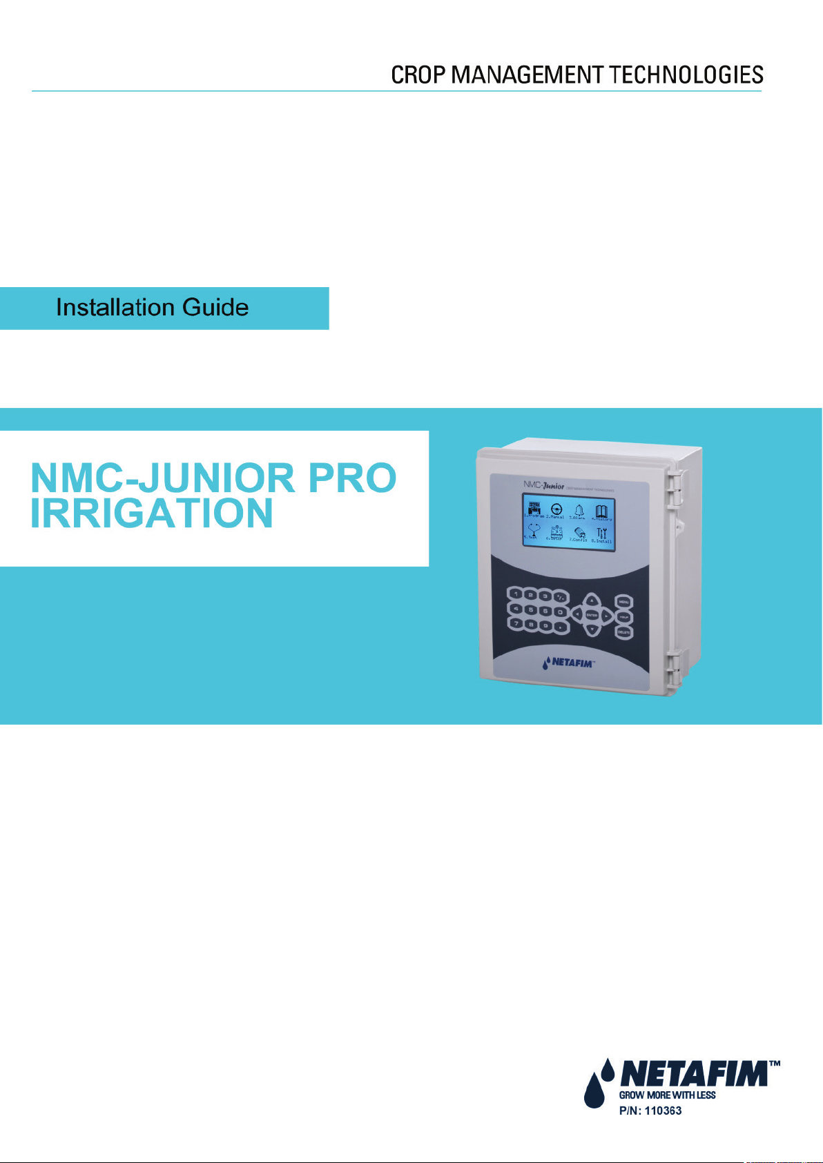
1.3 General Dimensions
Page 7
Page 8
NMC-Junior Pro Installation Manual
UNPACKING AND MOUNTING
2 UNPACKING AND MOUNTING
• Unpacking
• Box Installation
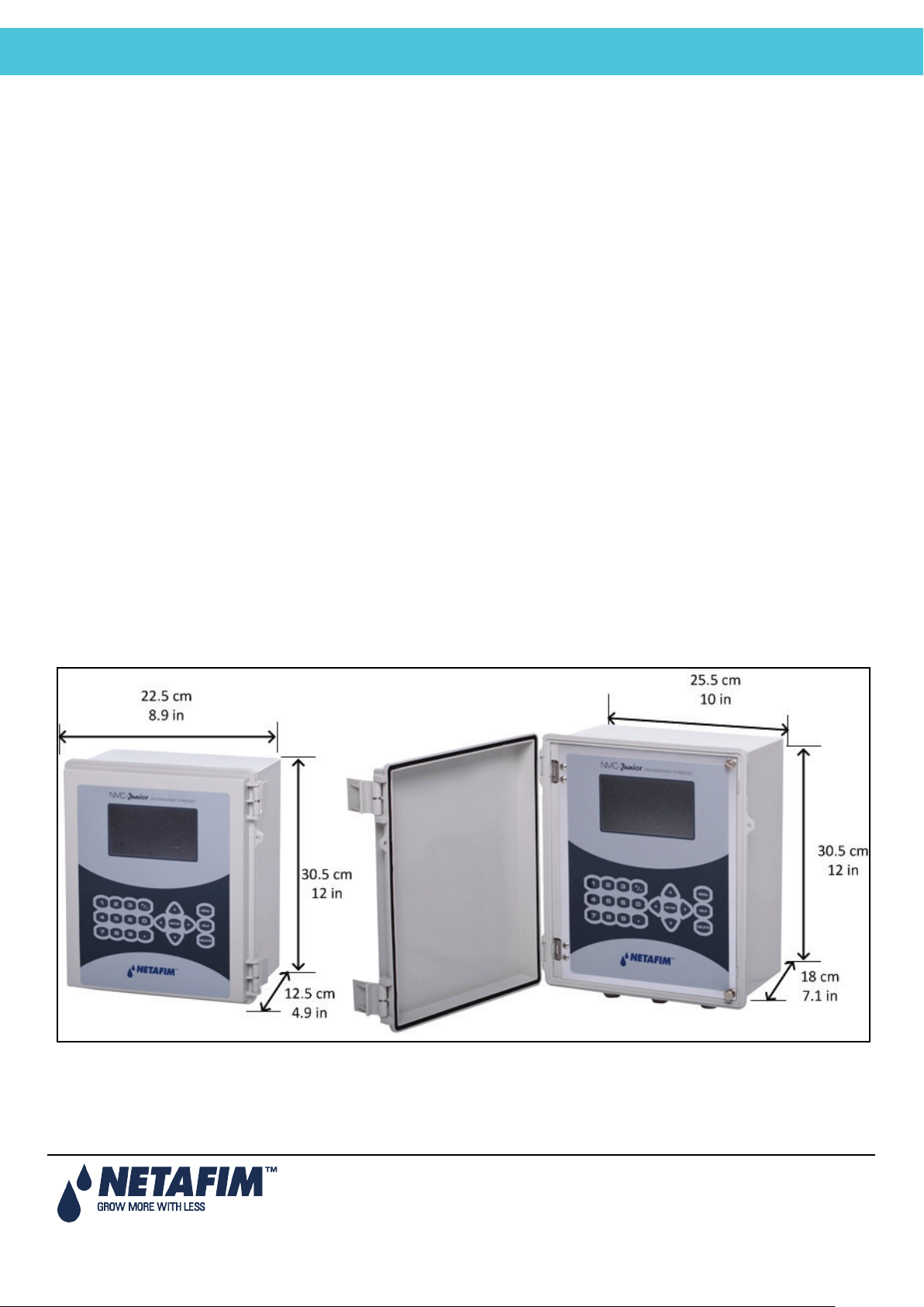
2.1 Unpacking
2.2 Box Installation
• Option A, page 9
• Option B, page 11
Page 8
Page 9
NMC-Junior Pro Installation Manual
UNPACKING AND MOUNTING
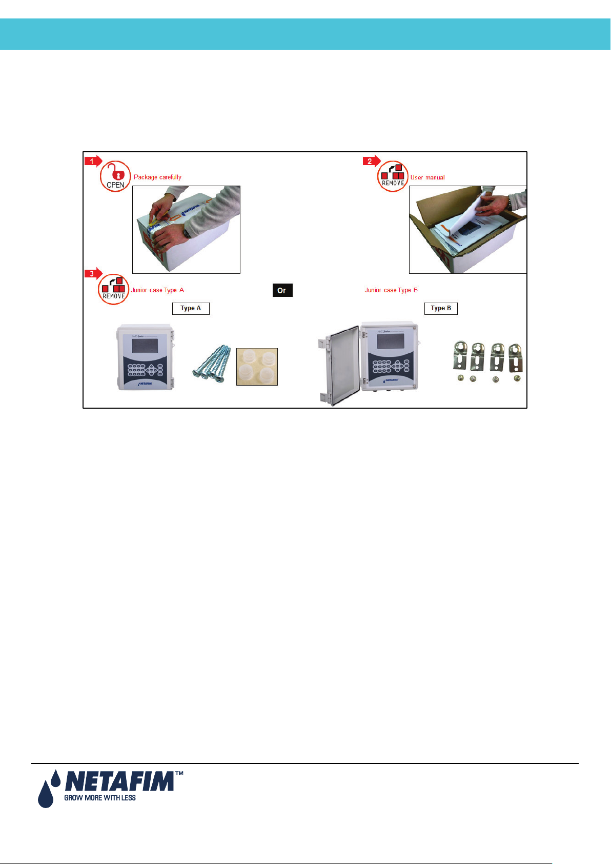
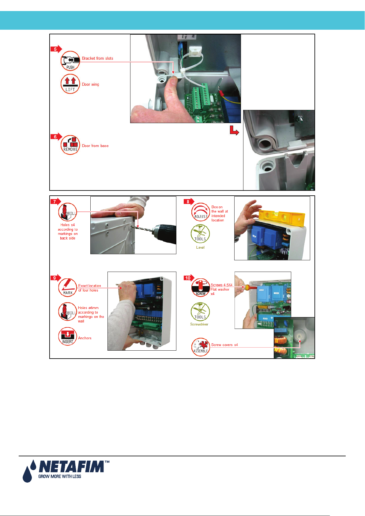
2.2.1 Option A
Page 9
Page 10
NMC-Junior Pro Installation Manual
UNPACKING AND MOUNTING
Page 10
Page 11
NMC-Junior Pro Installation Manual
UNPACKING AND MOUNTING
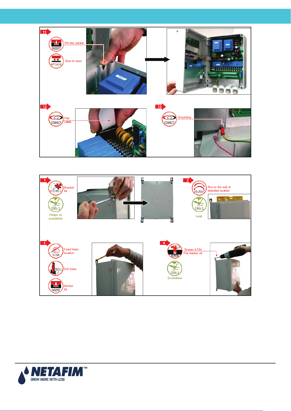
2.2.2 Option B
Page 11
Page 12

NMC-Junior Pro Installation Manual
Power Supply Wiring
3 POWER SUPPLY WIRING
• Main Power Wiring
• Electrical Test
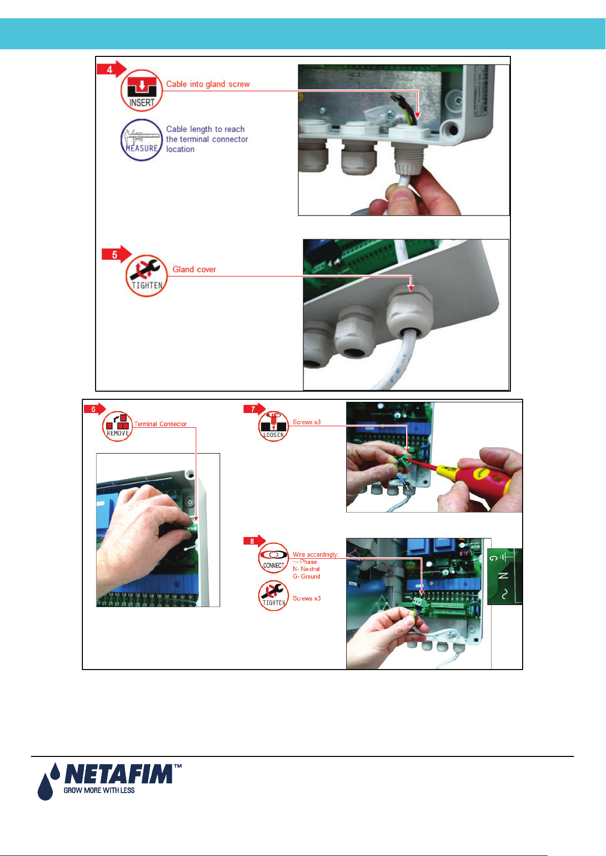
3.1 Main Power Wiring
Page 12
Page 13
NMC-Junior Pro Installation Manual
Power Supply Wiring
Page 13
Page 14
NMC-Junior Pro Installation Manual
Power Supply Wiring
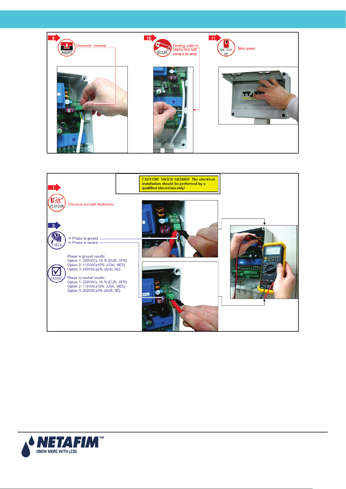
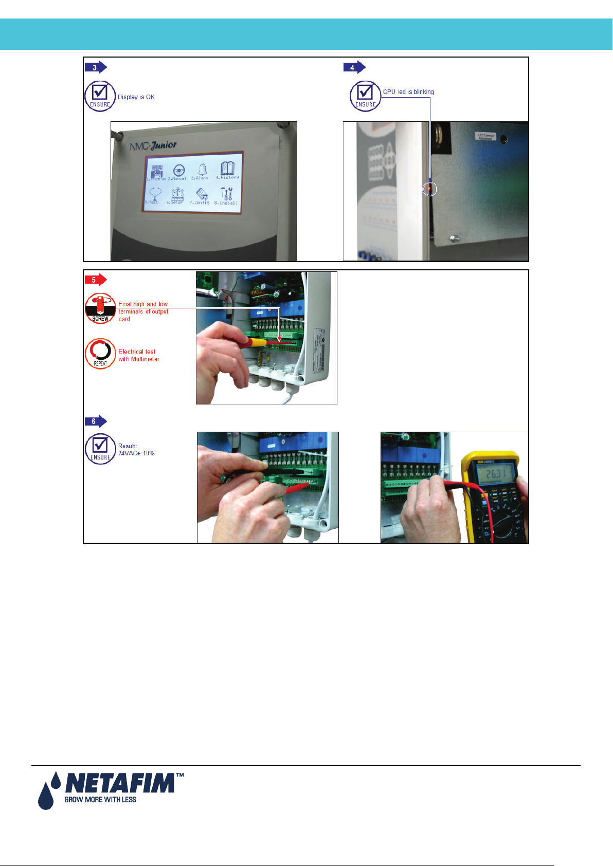
3.2 Electrical Test
Page 14
Page 15
NMC-Junior Pro Installation Manual
Power Supply Wiring
Page 15
Page 16
NMC-Junior Pro Installation Manual
Power Supply Wiring
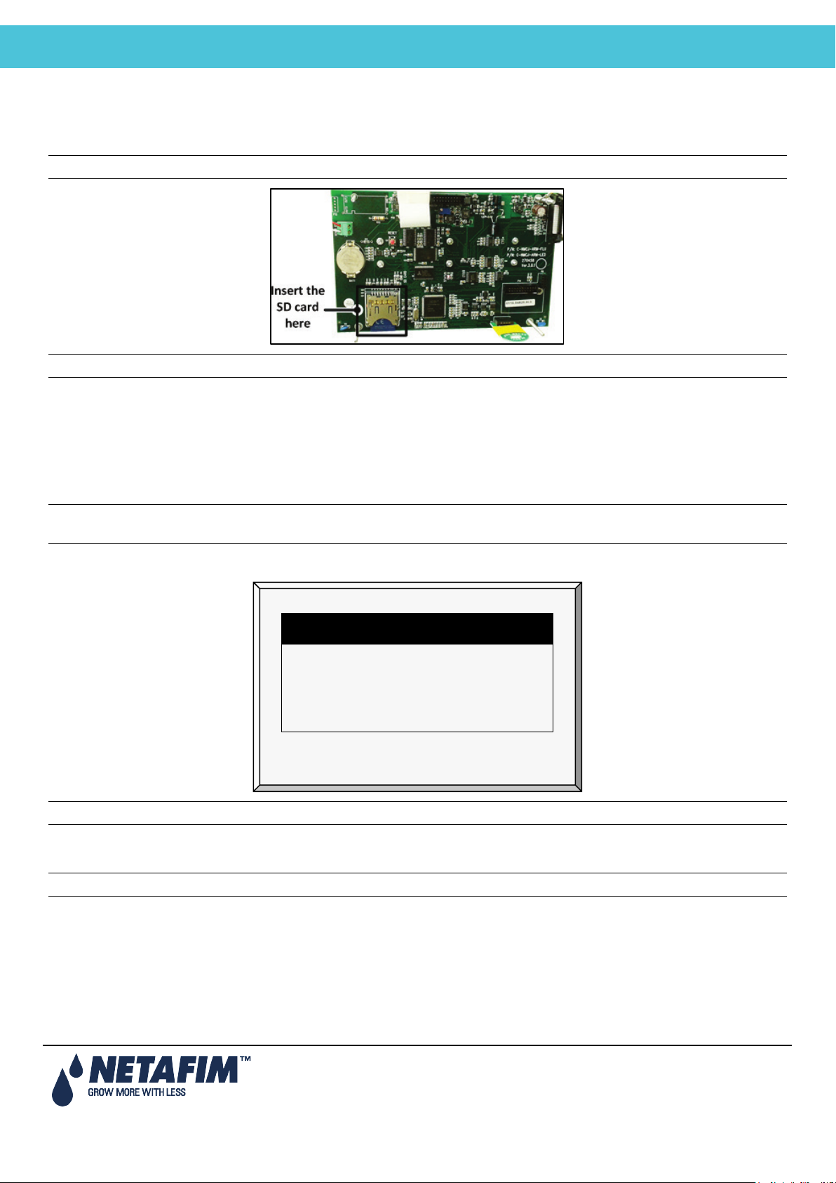
3.3 Firmware Upgrade
SELECT AN OPTION
Hardware Firmware
Hardware Test
Cancel Update
The Bootloader application enables installing or updating the system firmware. The application is menu based and
simple to use and enables updating the firmware from an SD card.
Note: Verify that the card is in place before starting.
Note: Junior Pro supports up to 4 GB SD cards.
3.3.1 Accessing the Application
1. Press and hold the Left and Down arrow keys.
2. Turn on the unit.
In the screen that appears, enter the password: 38845.
Note: If you enter the wrong password, an error message appears and the program goes to the Main Screen.
Repeat the process.
3. Press Enter. The screen below appears.
Note: Hardware Test is used for quality control only.
3.3.2 Running the Application
Note: Pressing Exit or ESC takes you to the previous menu.
1. Select Hardware Firmware. The following screen appears (example only):
Page 16
Page 17
NMC-Junior Pro Installation Manual
Power Supply Wiring
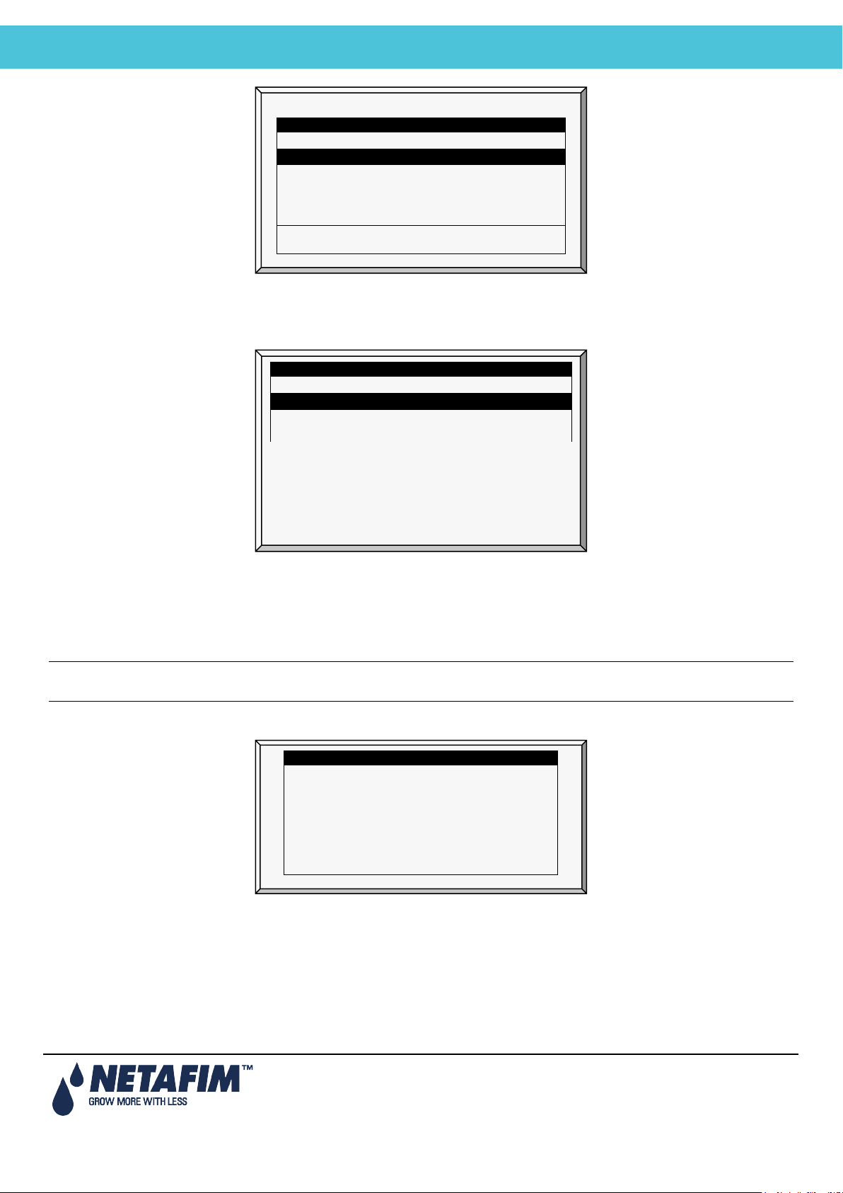
SELECT A FILE
Path: /
NMC_PRO <DIR> 13/Oct/2009
NEWPRO~1
<DIR>
12/Sept/2014
SELECT A FILE
Path: /
NETAFIMHEX1.04
<DIR>
12/Sept/2014
New Software Version
New Software Found
COLD START REQUIRED!!
New Version:
8.02.49
NETAFIM <DIR> 12/Sept/2014
Press ENTER to confirm selection or MENU to return.
2. Select the required directory.
3. Press Enter.
The following screen appears:
NMC_PRO <DIR> 13/Oct/2009
NETAFIMHEX1.06 <DIR> 12/Sept/2014
4. Select the required software version.
5. Press Enter.
6. A confirmation message appears. Select Yes.
7. Press Enter.
Note: Do not turn the unit off during the update! If there is an interruption (for example a power outage), restart the
process.
At the end of the process, the following screen appears (the version numbers are examples only):
Old Version: 8.02.00
Press ENTER To Continue.
8. Press Enter and perform a Cold Start.
Page 17
Page 18
NMC-Junior Pro Installation Manual
ELECTRICAL INSTALLATION
4 ELECTRICAL INSTALLATION
• Input/Output Layout, page 18
• Output Terminals, page 19
• Input Terminals, page 20
• PC and Inter-Controller Communication, page 23
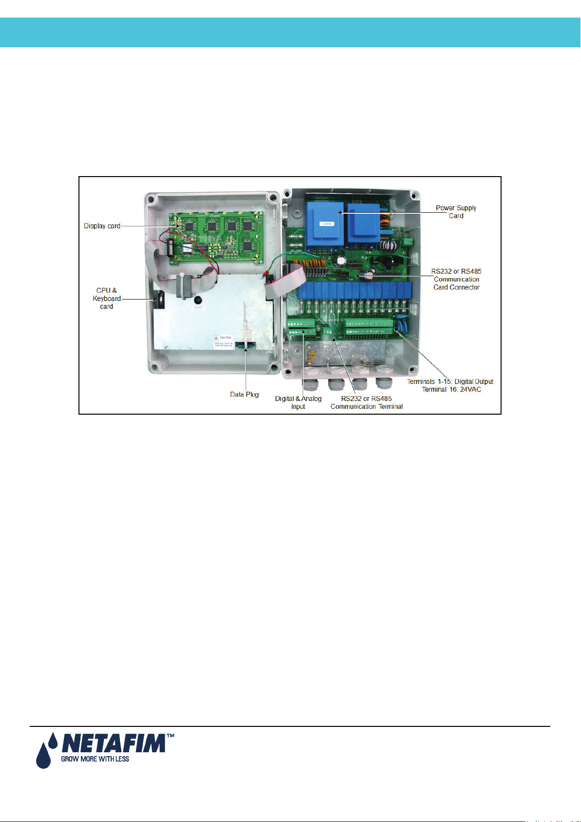
4.1 Input/Output Layout
Page 18
Page 19
NMC-Junior Pro Installation Manual
ELECTRICAL INSTALLATION
4.2 Output Terminals
• Output Terminal Wiring
• Example of Output Wiring
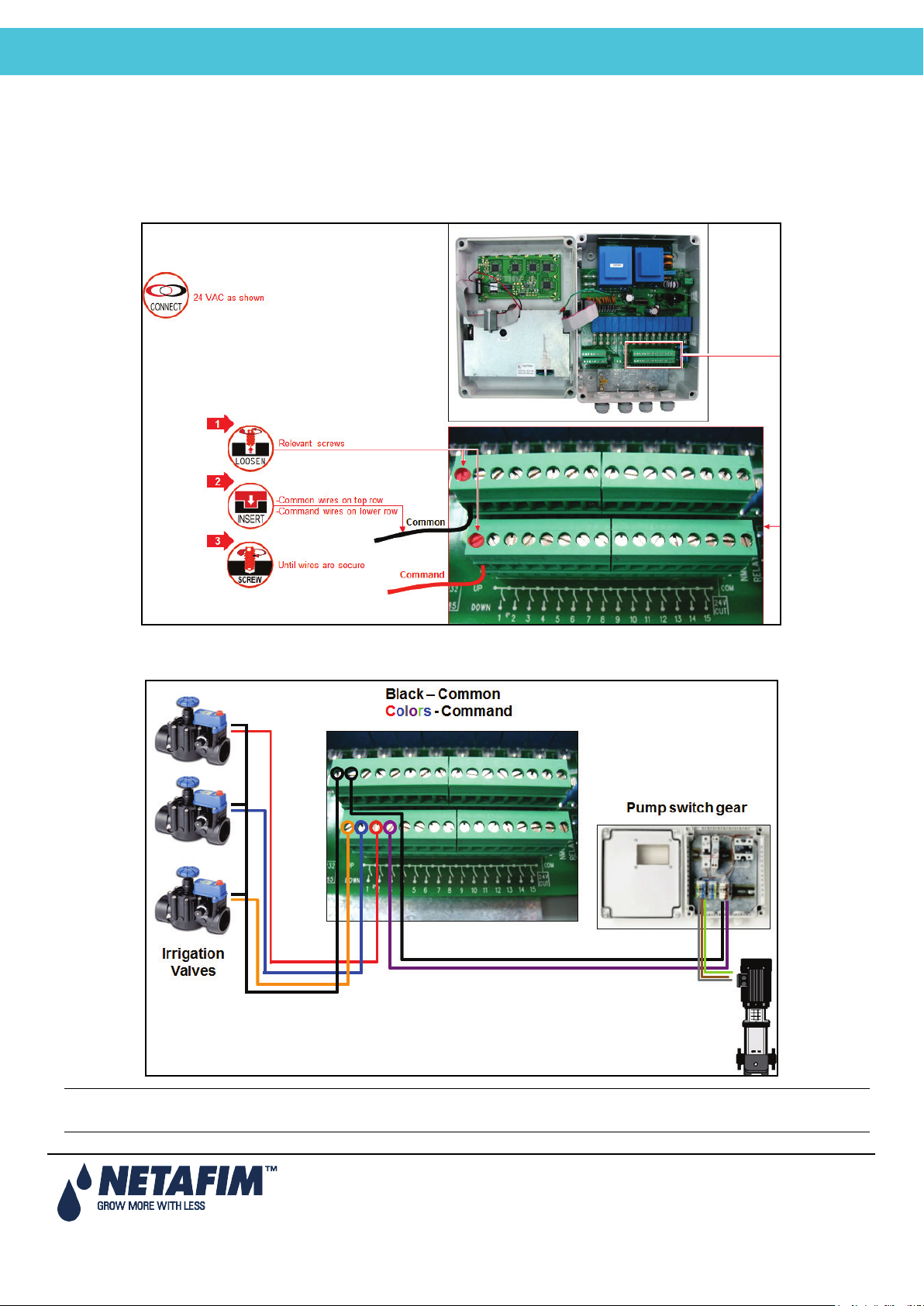
4.2.1 Output Terminal Wiring
4.2.2 Example of Output Wiring
Note: Before switching the controller on, the technician should verify that there is no short circuit on each output.
(Resistance test)
Page 19
Page 20
NMC-Junior Pro Installation Manual
ELECTRICAL INSTALLATION
4.3 Input Terminals
• Input Terminal Wiring
• Digital Input Examples
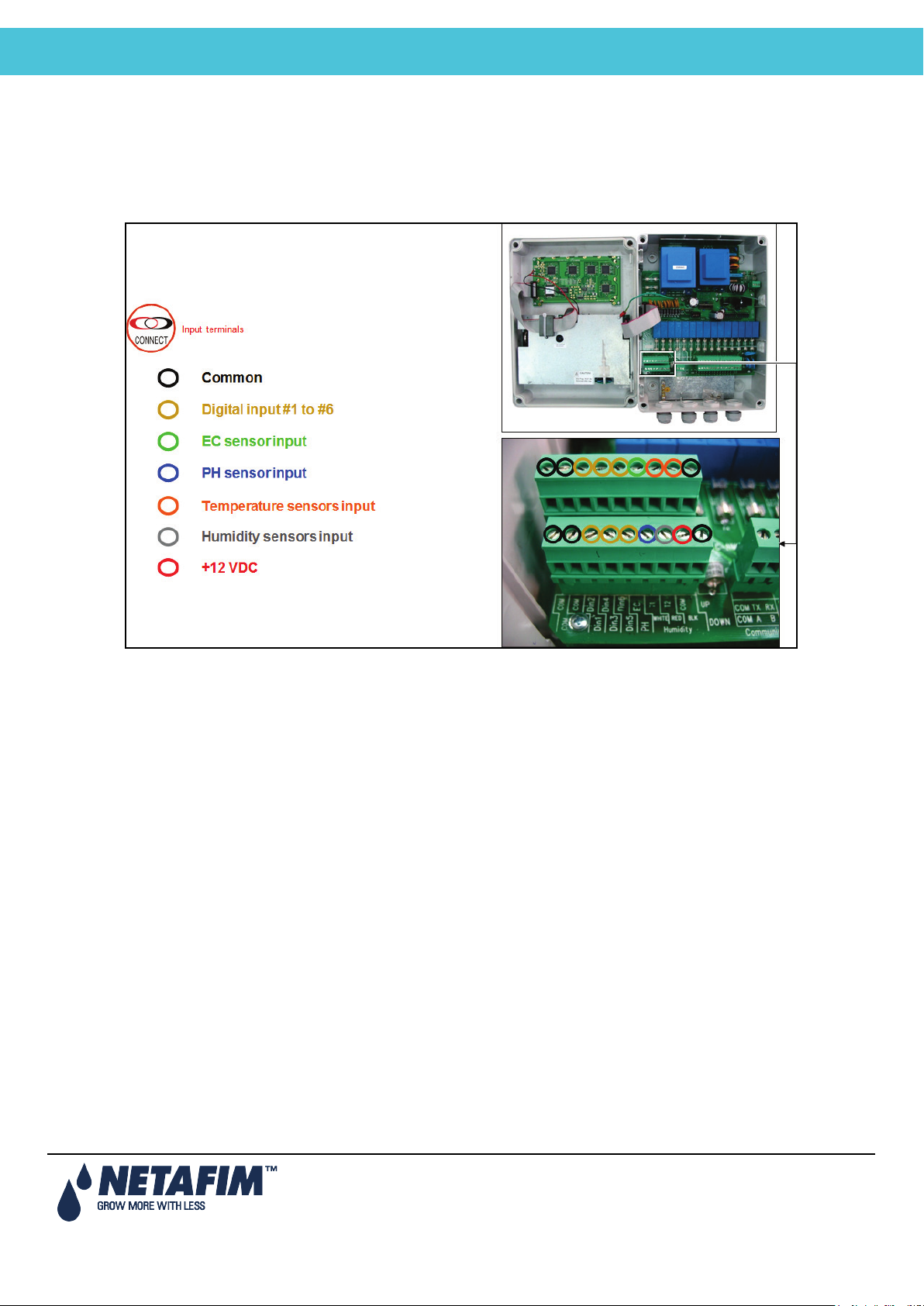
4.3.1 Input Terminal Wiring
Page 20
Page 21
NMC-Junior Pro Installation Manual
ELECTRICAL INSTALLATION
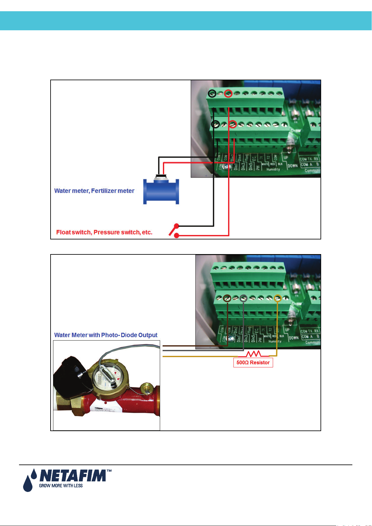
4.3.2 Digital Input Examples
• Example A
Digital input 1: Water meter, Fertilizer meter
Digital input 2: Float switch, Pressure switch
Digital Input 3: Water Meter with Photo-Diode Output
Page 21
Page 22
NMC-Junior Pro Installation Manual
ELECTRICAL INSTALLATION
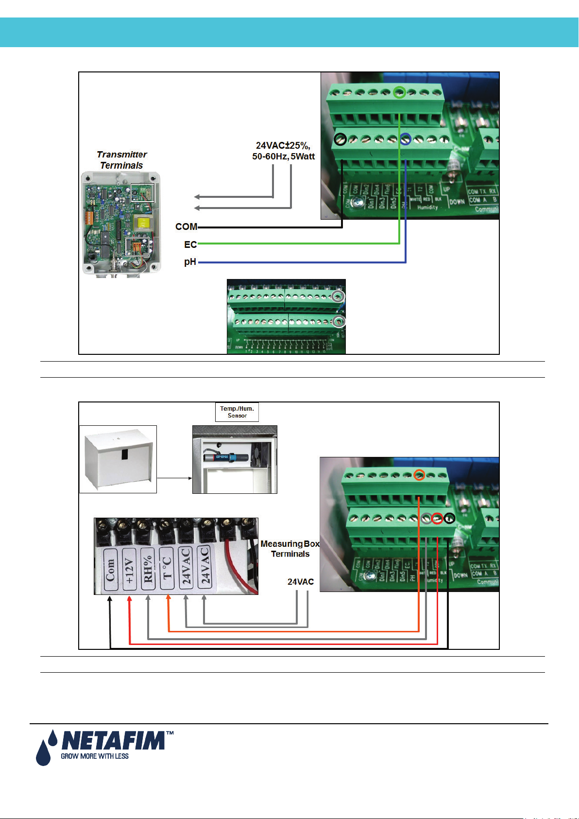
• Example B: EC / pH sensors
Can wire EC/pH main power source to 24VAC on the output terminals.
• Example C: Temperature / Humidity Sensors
Can wire 24VAC source in same way as on previous page.
Page 22
Page 23
NMC-Junior Pro Installation Manual
ELECTRICAL INSTALLATION
4.4 PC and Inter-Controller Communication
• Card Installation
• Wiring and Controller Setup
4.4.1 Card Installation
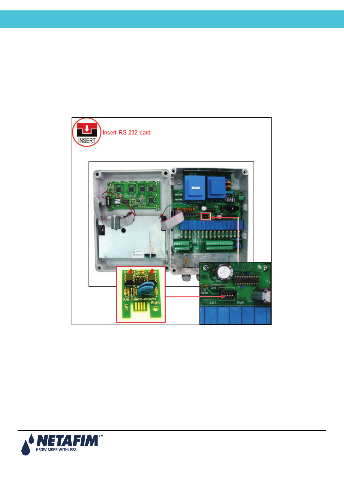
• Option A: RS-232 Card
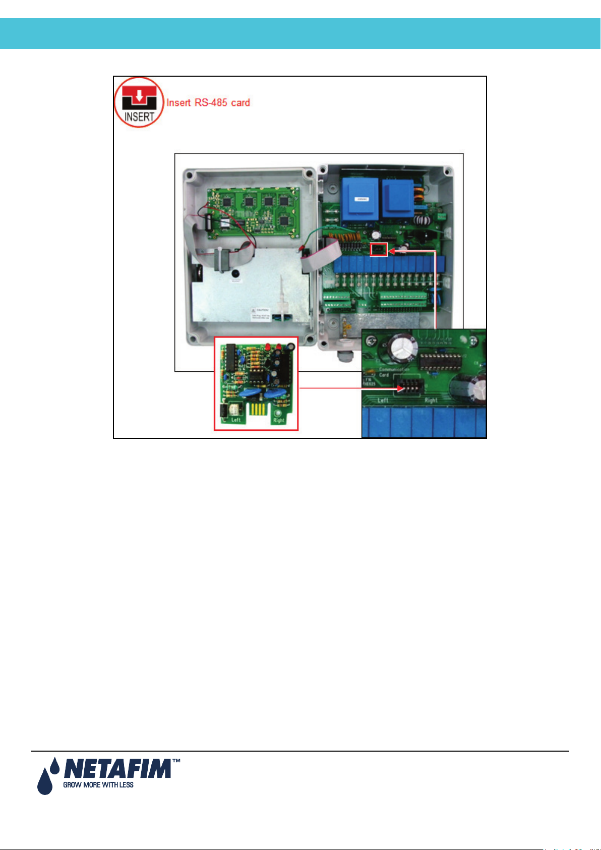
• Option B: RS-485 Card
4.4.1.1 Option A: RS-232 Card
Page 23
Page 24
NMC-Junior Pro Installation Manual
ELECTRICAL INSTALLATION
4.4.1.2 Option B: RS-485 Card
4.4.2 Wiring and Controller Setup
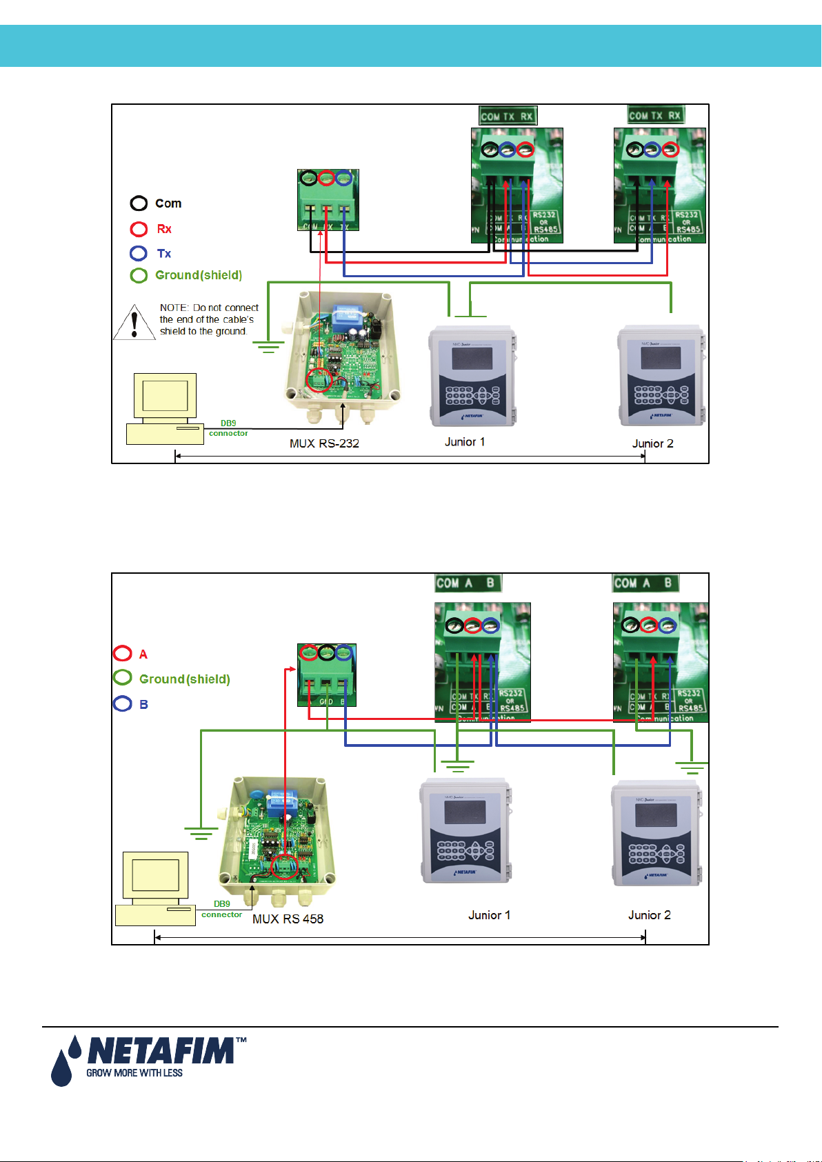
• Option A: RS-232 Setup
• Option B: RS-485 Setup
• Communication Distance and Baud Rate
Page 24
Page 25
NMC-Junior Pro Installation Manual
ELECTRICAL INSTALLATION
4.4.2.1 Option A: RS-232 Setup
• Use 3 wire shielded communication cable
• Do not connect the end of the cable’s shield to the ground.
• Refer to 4.4.2.3Communication Distance and Baud Rate.
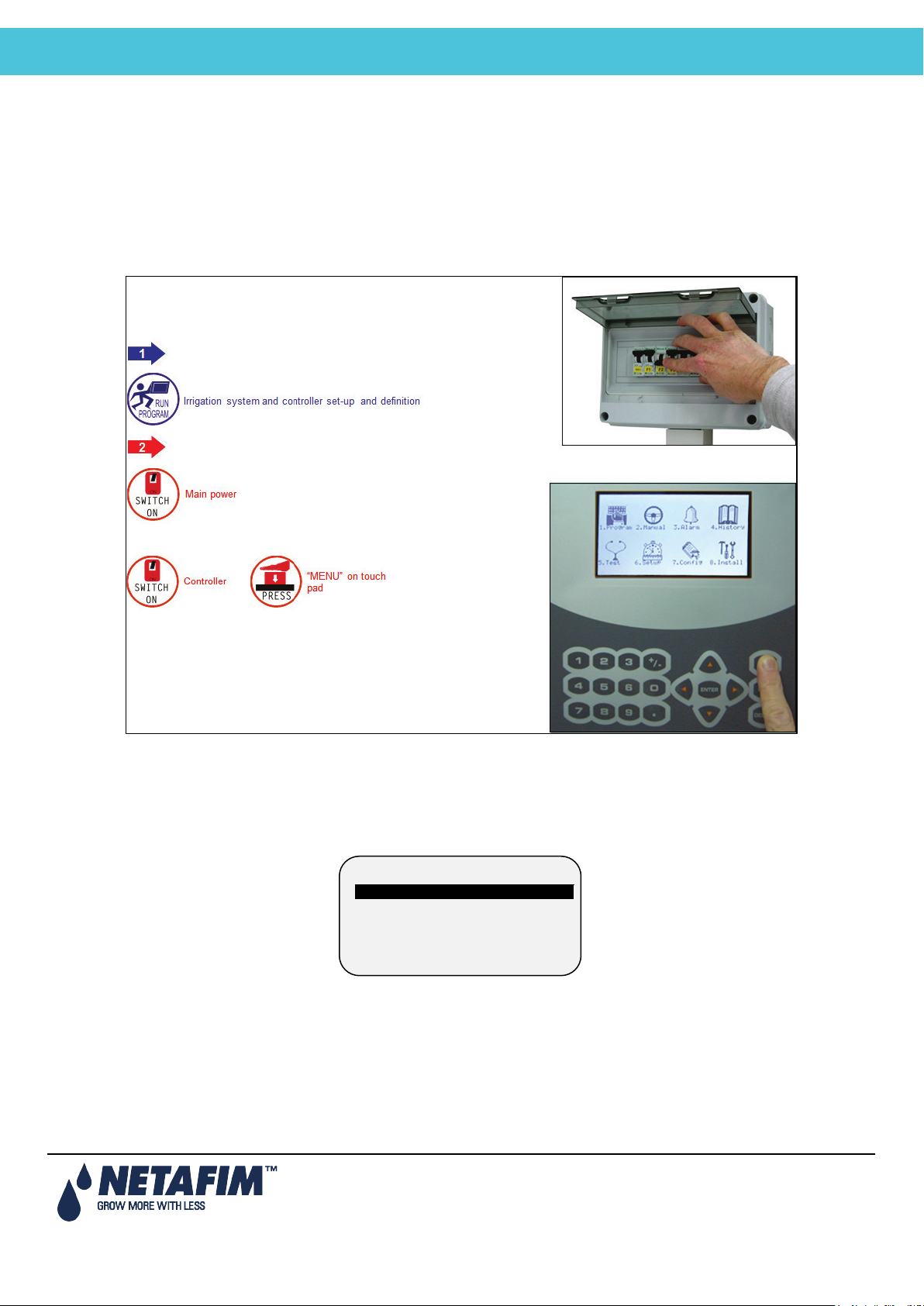
4.4.2.2 Option B: RS-485 Setup
• Use 2 wire shielded communication cable.
• Do not connect the end of the cable’s shield to the ground.
• Refer to 4.4.2.3Communication Distance and Baud Rate.
Page 25
Page 26

NMC-Junior Pro Installation Manual
ELECTRICAL INSTALLATION
4.4.2.3 Communication Distance and Baud Rate
Baud rate is dependent on cable length and number of controllers.
10 Controllers 1 Controller Baud Rate
1200 meter / 0.75 mile 2000 meter / 1.25 mile 9600 BPS
1800 meter/ 1.12 mile 2500 meter / 1.55 mile 4800 BPS
2400 meter /1.49 mile 3000 meter / 1.86 mile 2400 BPS
Page 26
Page 27
NMC-Junior Pro Installation Manual
CONTROLLER SETUP
5 CONTROLLER SETUP
INSTALLATION
• Start-Up
• Error! Reference source not found.
• Error! Reference source not found.
• Error! Reference source not found.
5.1 Start-Up
• Device Layout, page 27
• Device List, page 28
• Digital Input, page 28
5.2 Device Layout
1. DEVICE LAYOUT
2. DEVICE LIST
3. DIGITAL INPUT
4. ANALOG INPUT
The device layout screen allows you to assign functions to each output (relay).
1. Place the cursor on the Function column, use the arrow keys to reach the relevant line, and press ENTER. A
selection list including all available devices will appear.
2. Choose the required device and confirm by pressing ENTER. The cursor will move to the No. column.
3. Specify the number of the device in the controller and press ENTER to confirm.
4. If you wish to define several devices of the same type, for example valves 1 to 10, configure the first one and
press ENTER a few times until you reach the required amount. The NMC-Junior Pro automatically continues
with the same device until instructed otherwise, or until reaching the system limitation for that device.
Page 27
Page 28
NMC-Junior Pro Installation Manual
CONTROLLER SETUP
Note: If 'Radio' is selected in table 6.2, the screen contains at least 64 outputs.
Relay
Function
No
1
Valve
99
2
Valve
00
3
Valve
01
4
Valve
02
5
Valve
03
6
Valve
04
7
Valve
05
8
None
--
9
Valve
06
10
Pump
1
D-In
Input Function
1
Water Meter 1
2
Dosing Meter 1
3
Dosing Meter 2
4
< None >
5
< None >
6
Water Meter 2
DEVICE LAYOUT
Note: After making changes, be sure to exit and return again to check for errors. The NMC-Junior Pro will delete
and replace conflicting assignments with ‘---‘.
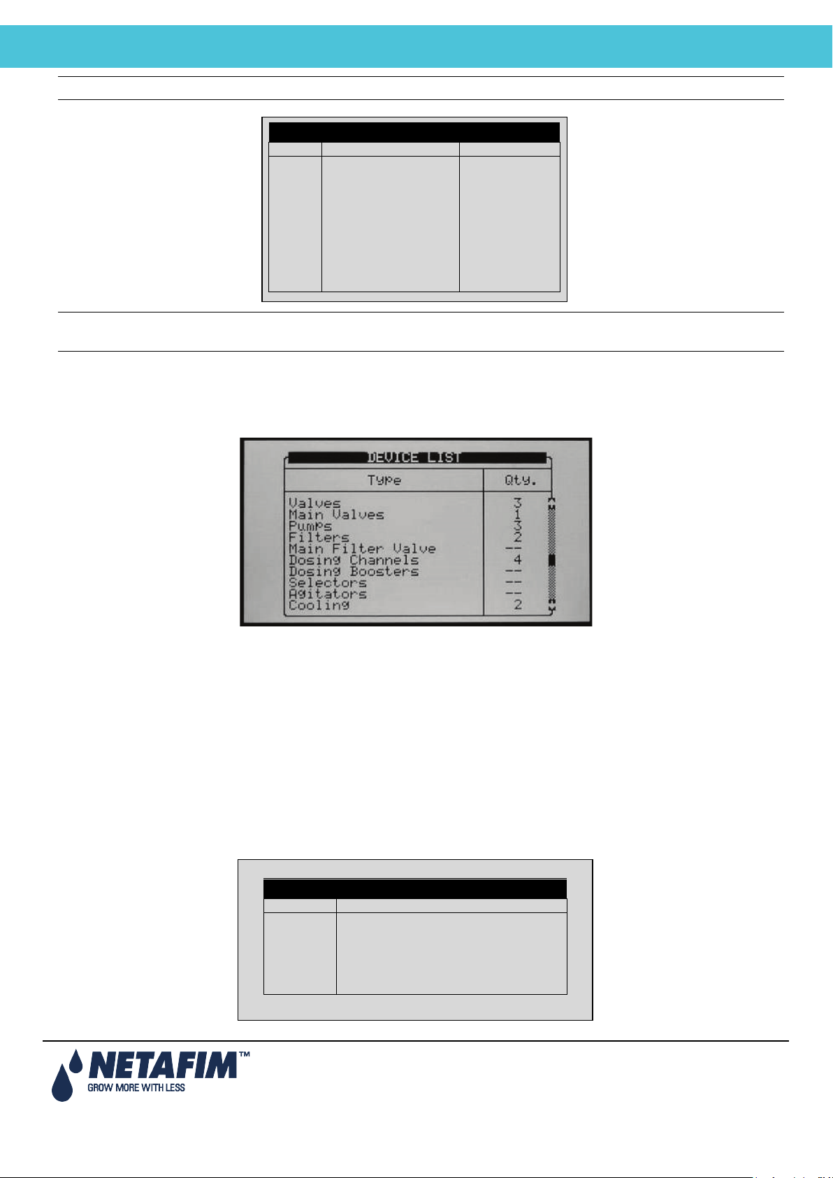
5.3 Device List
The Device List screen allows you to view what type, and how many devices are currently defined. This screen
automatically updates depending on the devices set in the 7.1 screen.
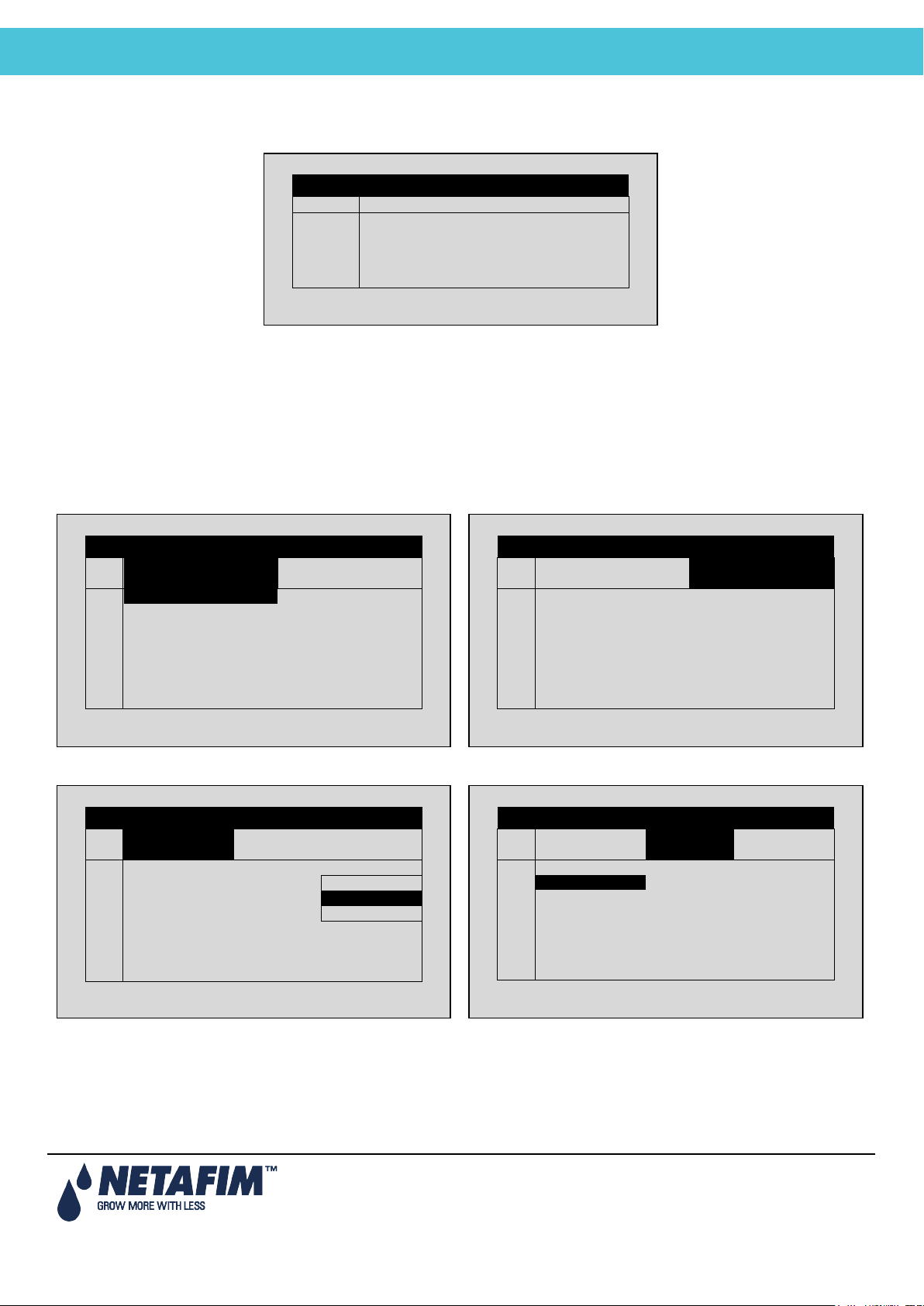
5.4 Digital Input
1. Go to Installation > Digital Input
2. Place the cursor on the relevant line and press ENTER. A selection list will open. Choose the required sensor and
press ENTER to confirm.
Inputs 1-32 are according to the following:
• Card no. 1: inputs 1 – 8
• Card no. 2: inputs 9 – 16
• Card no. 3: inputs 17 – 24
• Card no. 4: inputs 25 - 32
DIGITAL INPUT
Page 28
Page 29
NMC-Junior Pro Installation Manual
CONTROLLER SETUP
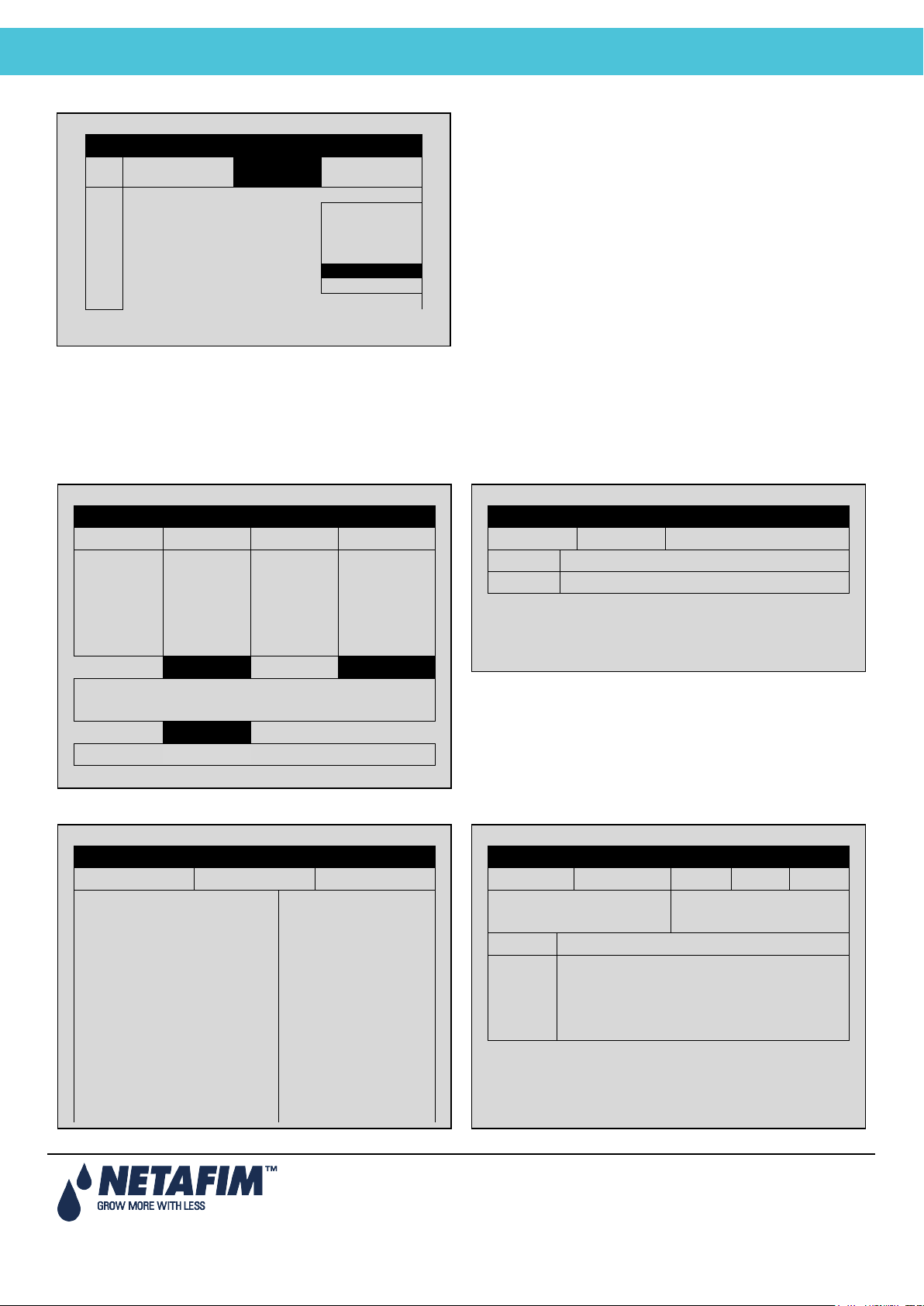
5.5 Analog Input
a. Enter the beginning and ending time for each
b. Under Start An. Dry Cont., define the input type.
c. Define The Trigger Type
d. Under Stop An. Dry Con., define the input type.
Channel
Input Function
Valid
1
pH Sensor
NO
2
EC Sensor
YES
3
Humidity Sensor
YES
4
Temp. Sensor 1
YES
5
Temp. Sensor 2
YES
#
From
hh:mm
To hh:mm
Start An.
Dry Cont.
1
10:00
12:00
2
11:00
12:00
Dry Con 1
3
12:00
13:00
Dry Con 1
4
--:--
--:--
<NONE>
5
--:--
--:--
<NONE>
6
--:--
--:--
<NONE>
7
--:--
--:--
<NONE>
8
--:--
--:--
<NONE>
#
From
hh:mm
To
hh:mm
Start An.
Dry Cont.
1 12:00
2 12:00
Dry Con 1
3 13:00
Dry Con 1
4 --:--
<NONE>
5 --:--
<NONE>
6 --:--
<NONE>
7 --:--
<NONE>
8 --:--
<NONE>
#
Trigger Type
Stop An
Dry Cont.
Oper.
to Start
1
Multi Shot
---
2
Multi Shot
Dry Con 2
One Shot
3
One Shot
Dry Con 14
Multi Shot
4
One Shot
<NONE>
Only If On
5
One Shot
<NONE>
---
6
One Shot
<NONE>
---
7
One Shot
<NONE>
---
8
One Shot
<NONE>
---
#
Trigger Type
Stop An
Dry Cont.
Oper.
to Start
1
---
2 Dry Con 2
---
3 Dry Con 14
---
4 <NONE>
--- 5
<NONE>
---
6 <NONE>
---
7 <NONE>
---
8 <NONE>
---
1. In Installation > Analog Input, define input function(s) as Analog Sensors.
ANALOG INPUT
2. In Setup > Analog Conversion Table:
a. Select the sensor type
b. Under Valid, select YES.
3. In Test > Analog Sensor, view the actual sensor values.
4. In Program > Ext Condition, configure the External Condition Program for the analog sensors.
program.
EXTERNAL CONDITION PROGRAM
EXTERNAL CONDITION PROGRAM
EXTERNAL CONDITION PROGRAM
EXTERNAL CONDITION PROGRAM
Page 29
Page 30
NMC-Junior Pro Installation Manual
CONTROLLER SETUP
e. Under Oper. to Start, choose the required symbol.
f. Under Start Value, enter the required value to start
EXTERNAL CONDITION PROGRAM
#
Stop An
Dry Cont.
Oper.
to Start
Start
Value
1
<NONE> >
2
Dry Con 2
---
3
Dry Con 14
---
4
<NONE>
---
5
<NONE>
---
6
<NONE>
---
7
<NONE>
---
8
<NONE>
---
the analog sensor. Under Stop Value, entered the
required value to stop the analog sensor.
5.6 Hot Keys and Status Screens
Hot Key 1: Next Irrigation Hot Key 2: Irrigation Process
SYSTEM SETUP
SET ACTUAL
CYCLE 1 1 START AT
WATER 00:10:00 00:10:00
FLOW 100.00 100.00
EC 1.5 LEFT
pH 5.3
STATUS ACTIVE
PROGRAM: 07:43:23 IRRIGATION
VALVE: 03-Apr-13 ALARM
MESSAGE
Hot Key 3: Program Status Hot Key 4: Water Flow & EC/pH Status
PROGRAM STATUS
Program: 1 3-Apr-13 09:12:35
Status Wait
Time - Minimum ---
Time - Maximum ---
Rad Sum – Measured/Limit —/—
Clock Starts – Given/Set —/—
Starts Due to Rad Sum ---
Starts Due to Max Time ---
Total Cycles Given 1
Last Start 12:00
Elapsed Time 3:00
Next Start 15:43
IRRIGATION PROCESS
Prog: Valve: Time: 08:07:23
Set Actual Flow Valve
Water
WATER EC/pH
Status Wait EC pH
Nom. Flow ------ Target --- ---
Act. Flow ------ Actual --- ---
Open(%) Min(%) Prg(%) Max(%)
Chan. 1 --- --- --- ---
Chan. 2 --- --- --- ---
Chan. 3 --- --- --- ---
Chan. 4 --- --- --- ---
Page 30
Page 31

NMC-Junior Pro Installation Manual
CONTROL TEST PROCEDURE
Hot Key 5: Filter Flushing Status Hot Key 6: Temperature and Humidity Status
FILTER FLUSHING STATUS
Item
Flush Status OFF
Time to Next Flush --:--:--
Delta Pressure (Digital) OFF
Flushing Filter No. --
Remaining Filters Qty. 0
Delay 00:00
Current Delta Pressure ----
TEMP & HUMIDITY
No. Temp. Humidity
1 <NONE> <NONE>
2 <NONE> ----
AVG. <NONE> <NONE>
Sen#T H VPD VPD SUM
<NONE> 0.0
Page 31
Page 32

NMC-Junior Pro Installation Manual
CONTROL TEST PROCEDURE
6 CONTROLLER TEST PROCEDURE
TEST
OUTPUT
FUNCTION
STATUS
1
DOSING CHANNEL 1
OFF
2
DOSING CHANNEL 2
OFF
3
DOSING CHANNEL 3
OFF
4
DOSING CHANNEL 4
OFF
5
DOSING CHANNEL 5
OFF
6
DOSING CHANNEL 6
OFF
7
DOSING CHANNEL 7
OFF
8
DOSING CHANNEL 8
OFF
1. RELAYS
2. DIGITAL INPUT
3. ANALOG INPUT
4. TEMPERATURE
5. HUMIDITY
The Test menu provides a quick way of verifying functionality.
• Relays, page 32
• Digital Input, page 32
• Analog Input, page 33
• Temperature, page 34
• Humidity, page 34
6.1 Relays
The Relays Test screen allows you to check the current output status and verify proper operation.
TEST RELAYS
The setting switches automatically between ON and Off depending on device actual status.
To manually test relay functionality, move the cursor to required device using the arrow keys and press ENTER; the
device is turned on and the setting shows MAN.
Press ENTER again to return to automatic operation.
• OFF: The output is not active.
• ON: The output is automatically turned on by the relevant program.
• Man: Manual operation of the output. The manual operation resets after 30 minutes of being idle, to prevent
you from forgetting to set it back to automatic operation.
• Load Output Level: Output level in A/D values. The value is constantly updated in accordance to relay
operation and output level change. This value is used to calculate the A/D threshold value to be considered as
a short circuit.
6.2 Digital Input
The Digital Input test screen allows you to verify the proper operation of digital inputs and sensors. Digital inputs are
defined as meters (water meters, dosing meters, etc.) that count the number of closed contacts from 0 to 255 and
Page 32
Page 33

NMC-Junior Pro Installation Manual
CONTROL TEST PROCEDURE
automatically restart back from 0. Other digital inputs (Dry contact, Ext. Pause, etc.) show either 0 when the contact is
DIGITAL VALUE
Channel
Value 1 59
2
0
3
0
4 0 5
0
6
0
Channel
Value
pH
564
EC
345
Hum.
376
Temp1
511
Temp2
453
open or 1 when the contact is closed.
Note that the card number is set according to its jumpers regardless to its location (local or extension box).
• Perform a dry test. Using a magnet, get a pulse. Attach the magnet to get a pulse from the read of the cable.
• Verify the water, fertilizer and any auxiliary meters.
Delta pressure: 1 = ON, 0 = OFF
6.3 Analog Input
Analog inputs will show values from 0 to 1023.
ANALOG INPUT
pH sensor
EC sensor
Humidity sensor
Temp sensor
Sensor type Description
pH = 0 – A/D = 205
pH = 7.0 – A/D = 615
pH = 14.0 – A/D = 1023
EC = 0 – A/D = 205
EC = 2.0 – A/D = 370
EC = 10.0 – A/D = 1024
RH% = 0 – A/D = 0
RH% = 50 – A/D = 308
RH% = 100 – A/D = 620
T°C = 0 – A/D = 768
T°C = 25 – A/D = 489
T°C = 50 – A/D = 250
Page 33
Page 34

NMC-Junior Pro Installation Manual
CONTROL TEST PROCEDURE
6.4 Temperature
No.
Value
1
27.3
2
28.6
No.
Value
1
57.3
This table shows the current temperature sensor readings in degrees (Celsius or Fahrenheit depending on the setup
in the screen).
TEMPERATURE
6.5 Humidity
This table shows the current humidity sensor readings in percentage relative humidity.
HUMIDITY
Page 34
Page 35

NMC-Junior Pro Installation Manual
SYSTEM CONFIGURATION PROCEDURE
7 SYSTEM CONFIGURATION PROCEDURE
CONFIGURATION
1. DEVICE DELAY CONFIGURATION
2. PUMP STATION CONFIGURATION
3. VALVE CONFIGURATION
4. VALVE FLOW RATE
5. WATER METER
6. DOSING CHANNEL CONFIGURATION
7. DOSING CONFIGURATION
8. DRAINAGE CONFIGURATION
9. EC/PH CONFIGURATION
10. COOLING CONFIGURATION
11. MISTING CONFIGURATION
• Device Delay Configuration, page 35
• Pump Station Configuration, page 38
• Valve Configuration, page 39
• Valve Flow Rate, page 40
• Water Meter, page 41
• Dosing Channel Configuration, page 42
• Dosing Configuration, page 43
• Drainage Configuration, page 44
• EC/pH Configuration, page 44
• Cooling Configuration, page 45
• Misting Configuration, page 45
• History Resolution, page 45
• System Nutrigation™ Check, page 46
7.1 Device Delay Configuration
The Device Delay Configuration screen enables defining the startup and shutdown order of the irrigation process.
• On (mm:ss): On is the definition of the startup order. The set times are taken from procedure startup. The
device with the shortest time will be started first and shifted to procedure startup. Therefore it is recommended
that the device that is to be started first be set as 00:00 (automatically changes to --:--).
• Off (mm:ss): Off is the definition of the shutdown order of the irrigation process. The set times are taken from
procedure shutdown. The device with the shortest time will be stopped first and shifted to procedure
shutdown. Therefore it is recommended that the device that is to be stopped first be set as 00:00
(automatically changes to --:--).
Page 35
Page 36

NMC-Junior Pro Installation Manual
SYSTEM CONFIGURATION PROCEDURE
7.1.1 Example of Device Startup & Shutdown Order
Stagger
1:00
1:30
00:20
VALVE 1
VALVE 2
MAIN
PUMP
• Startup: According to the settings above, the pump will be turned on first (on procedure startup). The main
valve will be opened after 1 minute later (one minute from procedure startup) the valve.
• Shutdown: According to the settings above the valve will be turned off first (on procedure shutdown). The
main valve will be closed after 15 seconds and the pump will be closed 20 seconds later (35 seconds from
procedure shutdown).
Note: It is recommended that the device that should be started (stopped) first be defined as zero
(will appear as --:--).
IN-PROGRAM DELAYS
• Shift delay (sec): Define the time (in seconds) between each valve change. The shift delay can also be a
shift advance by inserting a negative value. This means that the next valve will start before the previous one.
• Stagger delay (sec): Define the time (in seconds) for the first shift and the last shift delay between valves
(inside of group).
Stagger
00:20
0:15
00:35
mm:ss
Page 36
Page 37

NMC-Junior Pro Installation Manual
SYSTEM CONFIGURATION PROCEDURE
7.1.2 Example of Stagger Valve Delay – Multiple Shifts
Page 37
Page 38

NMC-Junior Pro Installation Manual
SYSTEM CONFIGURATION PROCEDURE
7.2 Pump Station Configuration
Pump
No.
Capacity
m3/h
Stability
mm:ss
Off Delay
mm:ss
1
----
--:--
--:--
Pump
No.
Capacity
m3/h
Stability
mm:ss
Off Delay
mm:ss
1
5.00
00:20
00:00
The NMC-Junior Pro can include up to six pumps. Each valve (irrigation, cooling or misting) can be connected to one
of the pumps or to the pump station. The pump station is a group of pumps (out of the six possible pumps) that will be
started in accordance with the required flow. The Pump Station configuration screen allows you to define which pumps
are part of the station, the capacity of the various pumps and their startup and shutdown delays.
Pump Station Configuration
Pump Station Configuration
The NMC-Junior Pro automatically calculates the expected flow and determines which pump (or pumps) should be
started (see Valve Configuration for additional information regarding flow calculation). The NMC-Junior Pro will start
the minimal number of pumps required to supply the calculated flow rate.
If several pumps should be started, the NMC-Junior Pro starts from the largest to the smallest and will turn them off
from the smallest to the largest.
• Pump No.: Pump number.
• Capacity: Define pump capacity in m3 or gallon. This will be the maximum pump capacity, above which the
NMC-Junior Pro will turn on another pump (if available).
• Stability (mm:ss): Define stability time. Stability time is the startup time required for current pump before next
pump can be started up. Stability time is usually used to prevent voltage drop down and water hammer (see
Pump Startup Order
• Off Delay (mm:ss): Define off delay. Off delay will be the delay time for current pump to stop after last pump
has stopped. This delay is usually used to prevent water hammer (see Pump Shutdown Order
• Station (Yes/No): Define whether the pump is part of the pump station.
The following is a startup and shutdown order schema according to the settings above and a calculated flow rate of 60
3
/h:
m
schema).
schema).
Pump 1
Pump 2
Pump 3
00:20
00:20
Figure 1: Pump startup & shutdown order
00:20
00:10
00:10
mm:ss
Page 38
Page 39

NMC-Junior Pro Installation Manual
SYSTEM CONFIGURATION PROCEDURE
7.3 Valve Configuration
Valve configuration allows you to configure devices such as pumps, main valves and drainage measurement of
valves.
• Valve No.: Indication of the valve number.
• Pump: Define which pump or pump station should be started when irrigating this valve. When choosing
Station, the NMC-Junior Pro will choose which and how many pumps should be started to supply the required
(calculated) flow. See
• Pump Station Configuration on page 38 for more information).
• Main Valve: Define which main valve should be opened when starting each valve.
• Water Meter: Configure a water meter to each valve. This option is only possible when the flow calculation
(water meter type) is Standard.
Note: Make sure that you define an operative water meter. There is no protection against defining a water meter
that isn’t properly defined in the system.
Note that when operating using Water Source (refer to Water Meter, page 41) a valve is not configured to a specific
water meter. In this case, all water meters set in the system are relevant for each irrigation; their pulses are calculated
for the flow rate. Therefore the Water Meter column is irrelevant in the Valve Configuration table.
Note: Make sure that you define an operative water meter. There is no protection against defining a water meter
that isn’t properly defined in the system.
Note: When using more than one water meter only start two valves that are configured to the same water meter;
the NMC-Junior Pro uses only the water meter connected to the leading valve and does not sum the flow from
the rest of the water meters. Dosing in this manner can create unexpected alarms and malfunctions!
• Drain Meter: Define which drain meter this valve is connected to.
• Drain Type: Define drainage type:
Total: Drainage is collected from the complete valve area.
Sample: Drainage is collected from a representing part of the valve area.
Note that it is possible to set several valves to the same drain meter when working by 'Total'. The system does not
allow operating several valves on the same meter when operating by 'Sample'.
• Sample %: When using sample drainage measurement it is required to define the ratio of the sample area to
the complete valve area.
Page 39
Page 40

NMC-Junior Pro Installation Manual
SYSTEM CONFIGURATION PROCEDURE
7.4 Valve Flow Rate
• Nominal: Define nominal valve flow rate (m3/h or gallon/min). The NMC-Junior Pro uses the set nominal flow
rate for calculating the ratio between valves when starting a few valves together, the boundaries for alarms,
the total flow rate for calculating how many pumps to start, etc. Therefore it is recommended to try and set the
nominal flow rate as close as possible to the actual flow rate.
• Minimum: Minimum valve flow rate, under which the system will generate a low flow alarm. When changing
the Nominal flow rate this setting is automatically set to 25% under the nominal flow, and can be manually
changed.
• Maximum: Maximum valve flow rate, above which the system will generate a high flow alarm. When changing
the nominal flow rate this setting is automatically set to 25% above the nominal flow, and can be manually
changed.
Note: When starting several valves simultaneously the system will sum their nominal, minimal and maximal flow
rates. An alarm will be generated only if the measured flow rate is lower than the total minimum, or higher than
the total maximum.
Note: When starting several valves simultaneously, the quantities between them will be divided based on the
ratio of their nominal flow.
Page 40
Page 41

NMC-Junior Pro Installation Manual
SYSTEM CONFIGURATION PROCEDURE
7.5 Water Meter
Description
Ratio
Type
Water Meter 1(L/P)
10.000
W.SOURCE
Water Meter 2(L/P)
20.000
W.SOURCE
Water Meter 3(L/P)
50.000
W.SOURCE
AUX Meter 1 (L/P)
----
--------
AUX Meter 2 (L/P)
----
--------
AUX Meter 3 (L/P)
----
--------
AUX Meter 4 (L/P)
----
--------
AUX Meter 5 (L/P)
----
--------
AUX Meter 6 (L/P)
----
--------
Description
Type
Sum
Water Meter 1(L/P)
W.SOURCE
+
Water Meter 2(L/P)
W.SOURCE
+
Water Meter 3(L/P)
W.SOURCE
+
AUX Meter 1 (L/P)
-------
--------
AUX Meter 2 (L/P)
STANDARD
--------
AUX Meter 3 (L/P)
W.SOURCE
--------
AUX Meter 4 (L/P)
--------
--------
AUX Meter 5 (L/P)
--------
--------
AUX Meter 6 (L/P)
--------
--------
Description
Ratio
Type
Water Meter 1(L/P)
10.000
STANDARD
Water Meter 2(L/P)
20.000
STANDARD
Water Meter 3(L/P)
50.000
STANDARD
AUX Meter 1 (L/P)
----
--------
AUX Meter 2 (L/P)
----
--------
AUX Meter 3 (L/P)
----
--------
AUX Meter 4 (L/P)
----
--------
AUX Meter 5 (L/P)
----
--------
AUX Meter 6 (L/P)
----
--------
• Ratio: Set volume per pulse of each water meter or auxiliary meter.
• Type: Define type of flow calculation:
Standard: In this function valves which are operated in a group should be connected to the same water
meter.
Note: If a few valves configured to different water meters will be started simultaneously, the NMC-Junior Pro
uses the flow measured by the water meter connected to the leading valve.
Water source: The NMC-Junior Pro will sum or deduct flow measured simultaneously from a few water
meters. When choosing this function an additional column called ”SUM” will appear, this column
enables to define which water meters should be summed and which deducted from the total measured
flow.
Note: Flow calculation type is a general definition for all water meters, therefore when changing type of water
meter for one of the water meters the type will be changed for all water meters.
Note: When setting flow calculation (water meter type) to Water source it is not possible to configure valves to
water meters.
• Sum: Define whether flow measured by each water meter should be added to the total measured flow or
deducted:
“+” Flow measured by this water meter will be added to the total measured flow.
“–” Flow measured by this water meter will be deducted from the total measured flow.
Note: Since flow cannot be negative, if the controller measures negative flow it will show zero.
Note: If all valves are set to "–" the system ignores the measured flow and will use the nominal flow (based on
the nominal flow).
WATER METER
WATER METER
WATER METER
Page 41
Page 42

NMC-Junior Pro Installation Manual
SYSTEM CONFIGURATION PROCEDURE
Note: It is very important to choose the correct flow meter for the application. Choosing a wrong flow meter might
result in measurement errors or an inaccurate control. For instructions regarding how to choose the correct water
meter see NMC-Junior Pro Irrigation > General > Flow meter determination.
7.6 Dosing Channel Configuration
• Pump: Select the type of dosing pump:
Venturi: The dosing unit consists of Venturi driven injectors. The dosing booster will be turned on when
fertigation is active.
Hydraulic: The dosing unit consists of hydraulic fertilizer pumps. The dosing booster is not needed and
will not be turned on when Fertigation is active. When working with hydraulic pump, the method can
only be Liter/Pulse and EC & pH control is not possible.
Electric: The dosing unit consists of electrical fertilizer pumps. The dosing booster is not needed and
will not be turned on when Fertigation is active.
• Method: Select the operating method:
Liter/Pulse: Define whether a dosing meter is connected to this channel and used for control purposes.
Set the volume per pulse on the Ratio column.
Time (cc/sec): Define whether the calculated flow rate of the dosing channel is in CC (gallons) of
fertilizer per second.
Time (Liter/min): Define whether the calculated flow rate of the dosing channel is in liters (gallons) per
minute.
Time (Liter/Hour): Define whether the calculated flow rate of the dosing channel is in liters (gallons) per
Hour.
• Ratio
Method is Time: Define calculated flow rate, this will be the flow rate of the channel when completely
open.
Method is Liter/Pulse: Define the volume per pulse.
• React: Set the required use of the channel:
EC: The channel is used to increase measured EC, meaning it will be opened more when the measured
EC is lower than the set EC.
pH: The channel is used to decrease measured pH, meaning it will be opened more when the
measured pH is higher than the set pH.
Passive: The channel does not respond to changes in measured EC/pH, meaning it will be opened as
set in the dosing program regardless of the EC/pH values.
Alkali: The channel is used to increase measured pH, meaning it will be opened more when the
measured pH is lower than the set pH.
Note: If EC/pH control is off, or the channel is used for proportional injection only (for example in order to inject
chemicals) set reaction to passive.
• High %: set an injection percentage limit. This percentage will limit the deviation from set dosing recipe when
NMC-Junior Pro is injecting more than specified in order to try and reach the target EC/pH values.
• Low %: set an injection percentage limit. This percentage will limit the deviation from set dosing recipe when
NMC-Junior Pro is injecting less than defined in order to try and reach the target EC/pH values.
Page 42
Page 43

NMC-Junior Pro Installation Manual
SYSTEM CONFIGURATION PROCEDURE
• V/P(L/G): This parameter is disabled when operating by Liter/Pulse. Define the volume per pulse of the
dosing meter (liters or gallons). Only required when using a dosing meter for measurement and alarm
purposes. When using a dosing meter for control purposes the volume per pulse of the dosing meter should
be defined on the Ratio column. The letter between the brackets indicates whether the volume units are in
Liter or Gallon.
7.7 Dosing Configuration
• EC Control: Define whether EC control should be operative.
• pH Control: Define whether pH control should be operative.
• EC Alarms: Define whether EC related alarms are operative. When EC control is set to ‘Yes’, EC Alarms are
automatically set to ‘Yes’ and cannot be changed.
• pH Alarms: Define whether pH related alarms are operative. When pH control is set to ‘Yes’ pH Alarms are
automatically set to ‘Yes’ and cannot be changed.
• Minimum On Time (sec): Define the minimum time the dosing regulator can be open. This feature is used to
protect the regulator from being excessively turned on and off. The minimum allowed on time is 0.4 seconds.
• Minimum Off Time: Define the minimum time the dosing regulator can be off. This feature is used to protect
the regulator from being excessively turned on and off. The minimum off time allowed is 0.4 seconds.
• EC Coarse Tuning (0-10): EC Coarse Tuning is used to adjust the speed and strength of the EC control. A
higher value will result in faster correction but might lead to over shooting (see Appendix 1 – General > EC/pH
correction adjustment for further information).
• EC Fine Tuning (0-10): EC Fine Tuning is used to fine tune the EC control shooting (see NMC-Junior Pro
Irrigation > Part 2 > General > EC/pH correction adjustment for further information).
• pH Coarse Tuning (0-10): pH Coarse Tuning is used to adjust the speed and strength of pH control. A higher
value will result in faster correction but might lead to over shooting (see NMC-Junior Pro Irrigation > Part 2 >
General > EC/pH correction adjustment for further information).
• pH Fine Tuning (0-10): pH Fine Tuning is used to fine tune pH control shooting (see NMC-Junior Pro
Irrigation > Part 2 > General > EC/pH correction adjustment for further information).
• Control Cycle (sec): Define the control cycle for EC/pH control. This should be the time it takes the system
since it injected fertilizer/acid until the change in recognized by the system.
• EC/pH Averaging (0-Low, 20-High): Averaging factor for EC/pH measurement. EC/pH averaging should be
used to enable correction when injection is not homogenous.
• Dosing Booster Off Delay (mm:ss): Define the time that the dosing booster should be left on after dosing
has ended. This time is usually used to circulate the acid and nutrients in order to prevent high concentrations
in the area of the venturies and dosing booster when the system is idle.
• Dosing by QTY. Method:
Bulk: All channels set to QTY (quantity) dosing method will inject the set quantity in one bulk, starting
after water before quantity/time has elapsed.
Spread Out: The set dosing quantity of all channels set to QTY (quantity) dosing method will be spread
throughout the irrigation.
Page 43
Page 44

NMC-Junior Pro Installation Manual
SYSTEM CONFIGURATION PROCEDURE
7.8 Drainage Configuration
Sensor
4 mA
20 mA
EC 0 10
pH 0 14
• Ratio: Define volume per pulse of the drainage meters (liter/pulse or gallon/pulse).
• On Delay: Define how long a valve, which is configured to this drainage measurement, should be open before
the measured drainage is related to this valve. All drainage measured before this time has elapsed (although
the valve is open) will still be related to the previous opened valve that was configured to this drainage sump.
• Off Delay: Define how long after irrigation has finished, the measured drainage should still be related to the
previous irrigation. This value is used to “tell” the NMC when to stop relating drainage to the previous irrigation
and write it to all relevant history tables.
7.9 EC/pH Configuration
EC/pH CONFIGURATION
Define the range of the EC/pH transmitters.
• Default settings for Netafim EC/pH transmitters is:
EC: zero to 10 mS
PH: zero to 14 ppm
• EC Control Sensor: Define which EC sensor should be used for control. When setting EC 1 + EC 2, EC1 will
be used for control, and EC2 will be used for verification.
• pH Control Sensor: Define which pH sensor should be used for control. When setting pH 1 + pH 2, pH1 will be
used for control, and pH2 will be used for verification.
Page 44
Page 45

NMC-Junior Pro Installation Manual
SYSTEM CONFIGURATION PROCEDURE
7.10 Cooling Configuration
1. Select Controller number (in case of multiple controllers in the network, name each controller with a different
SETUP
The cooling configuration screen will only be visible after one (or more) cooling valves have been defined in the
DEVICE LAYOUT
• Pump: Configure a pump to each cooling valve. This setting is not necessary if the cooling pump is not
controlled by the NMC-Junior Pro.
• Main Valve: Configure a main valve to each cooling valve. This setting is not necessary if the cooling doesn’t
have a main valve.
table.
7.11 Misting Configuration
• Pump: Configure a pump for each misting valve. This setting is not necessary if the misting pump is not
controlled by the NMC-Junior Pro.
• Main Valve: Configure a main valve to each misting valve. This setting is not necessary if the misting doesn’t
have a main valve.
7.12 History Resolution
Program how often the computer collects sensor data (keep in mind that lower resolution fills the memory in short
period and overwrites the old data).
1. TIME & DATE
2. SYSTEM SETUP
3. TEMPE RATURE CALIBRATION
4. HUMIDITY CALIBRATION
5. EC/PH CALIBRATION
6. SENSOR LOGGING
7. WRITE TO DATA P LUG
8. READ FROM DATA PLUG
number
Page 45
Page 46

NMC-Junior Pro Installation Manual
SYSTEM CONFIGURATION PROCEDURE
2. Select the communication baud rate between controllers and the PC
SYSTEM SETUP
Language
Temperature Unit
°C
Volume Unit
Metric
Maximum Cooling Parallel
1
Maximum Misting Parallel
1
STOP IRRIGATION
During Filter Flushing
No
During Cooling Process
No
During Misting Process
No
STOP DOSING
During Filter Flushing
No
Main Screen
Default Hotkey Number
5
History
History Resolution
1 Hour
Weather Station
Controller Function
LOCAL
Operation Mode
Automatic return to RO mode
NO
Return period to RO mode
00:10
Communication
Controller Number
1
Port Protocol
NMC NET
Baud Rate
9600
7.13 System Nutrigation™ Check
• Check if EC/pH is on Target
• Water Run Time
• Start/Stop Valve
7.13.1 Check if EC/pH is on Target
SYSTEM SETUP
1. Go to Program > Dosing.
2. Enter required amount of fertilizer to inject per dosing channel in l/m³ (USA: Gallon/1000 gallon)
3. Enter required target EC/PH levels.
7.13.2 Water Run Time
Page 46
Page 47

NMC-Junior Pro Installation Manual
SYSTEM CONFIGURATION PROCEDURE
7.13.3 Start/Stop Valve
Page 47
Page 48

NMC-Junior Pro Installation Manual
CONTROLLER ADVANCED FEATURES
8 CONTROLLER ADVANCED SETTINGS
• Pump Station Configuration
• Multiple Water Meters
• Various Dosing Configurations
• Dosing Configuration
• Error! Reference source not found.
• Hot Keys and Status Screens
8.1 Pump Station Configuration
8.2 Multiple Water Meters
Only one water meter can be measured at a time.
Page 48
Page 49

NMC-Junior Pro Installation Manual
CONTROLLER ADVANCED FEATURES
8.3 Various Dosing Configurations
• Method 1
• Method 2
• Method 3
8.3.1 Method 1
• Dosing pump control = Fert. Meter
• Dosing pump measurement = Fert. Meter
• Dosing pump type = Venturi or Electric
8.3.2 Method 2
• Dosing pump control = Nominal Flow Rate
• Dosing pump measurement = Calculate dosing pump flow rate
• Dosing pump type = Venturi or Electric
8.3.3 Method 3
• Dosing pump control = Fert. meter
• Dosing pump measurement = Fert. Meter
• Dosing pump type = Hydraulic
Page 49
Page 50

NMC-Junior Pro Installation Manual
CONTROLLER ADVANCED FEATURES
8.4 Dosing Configuration
• EC/pH Control Step 1
• EC/pH Control Step 2
8.4.1 EC/pH Control Step 1
System injects ± depending on EC levels, auto-adjust to meet target levels. Set limits for controller adjustments when
levels are too high/low/
Example: If dosing Channel 1 is set by the grower to inject 10 liter/m3, the controller auto adjust range is 5 to 15
liter/m3 in order to meet the EC level.
8.4.2 EC/pH Control Step 2
• EC/pH coarse tuning: When way off target, faster/stronger correction
• EC/pH fine tuning: Off target is low, slow/light correction
• Control cycle: Delay time from fertilizer/Acid injection point to EC/pH sensors reading
• EC/pH averaging: Balanced reading from EC/pH sensors
• Dose boost off delay: Time clear water circulated through system after fertigation stops and Venturi closes
Page 50
Page 51

NMC-Junior Pro Installation Manual
PROGRAM MENU
9 PROGRAM MENU
In the Main Menu screen, place the cursor on the program icon and press ENTER, or press '1' to enter the Program
Menu.
• Irrigation, page 51
• Using the Influences, page 55
• Setting the Influences, page 55
• Water Run Time, page 60
• Dosing, page 61
• Ext. Condition, page 63
• Agitator, page 64
• Selector, page 65
• Filter Flushing, page 65
• Cooling, page 66
• Misting, page 68
• Water Heating, page 69
Note: To enter any of the menus, press the corresponding numeric key or scroll to the desired item using the
up/down arrow keys and press ENTER: a new window will appear. The first menu under Program is Irrigation.
9.1 Irrigation
The Irrigation Program screen includes all the settings for configuring automatic irrigation start. It depends heavily on
the Water Run Time and dosing program screens; therefore it is recommended to configure these screens before
irrigation takes place.
The NMC-Junior Pro consists of 15 irrigation programs.
Page 51
Page 52

NMC-Junior Pro Installation Manual
PROGRAM MENU
• Program: Select a program by entering the program number and confirm by pressing ENTER.
• Priority: Priority determines the order in which programs will take place. If start time is the same, higher
priority programs come first. Higher priority programs do not stop currently operative programs.
If start time and priority are the same, irrigation programs with a lower number are executed first. Priority
ranges are between 0 and 15, 15 being the highest (See NMC-Junior Pro Irrigation – Part 2 > Priority
specifications for further information).
• Const / Daily / Cond. / Rad Sum / VPD Sum:
CONST.: Increase or decrease the amount of water for all valves included in this program. 0% means
the quantities will be as specified in the Water Run Time program, 100% will be twice the amount and
–50% will be half the amount specified in the Water Run Time Program. To decrease enter the
required percentage of change, press the +/- key and confirm with the ENTER key. The percentage of
change is active until you specify otherwise.
DAILY: Increase or decrease the amount of water for all valves included in this program. 0% means the
quantities will be as specified in the Water Run Time program, 100% will be twice the amount and –
50% will be half the amount specified in the Water Run Time Program.
To decrease, enter the required percentage of change, press +/- key and confirm with the ENTER key.
The percentage of change will be active only for the present day and will change automatically back to
zero on End Day time.
Note: CONST. % and DAILY % does not change Quantity / time of water before and water after settings, nor
dosing quantities.
Note: When setting watering program and using 'Spread' the percentage affects not only the water but also the
dosing.
Cond.: Specify whether the Condition program can trigger irrigations, and choose a Condition program
to start/stop irrigations. Irrigations will be started and stopped according to the settings of the relevant
Condition program (see Ext. Condition, page 63, for additional information). If irrigation is not triggered
due to Condition program until Max time has elapsed irrigation will be performed due to Max time.
When choosing Condition, the screen will be split in two. To view the day sequence, press the Down
arrow when the cursor is placed on the bottom of the screen.
The Condition program has the third priority after active irrigation and uncompleted irrigation (See
NMC-Junior Pro Irrigation – Part 2 > Priority specifications for further information).
Page 52
Page 53

NMC-Junior Pro Installation Manual
PROGRAM MENU
Note: It is impossible to set the same Condition program for two different programs.
DATE : 1-May-12 TIME : 10:12:09
Program: 2
Priority: --
Rad Sum
Start Time
Max. Time
07:00
02:00
12:00
--:--
16:00
--:--
Valve #
Dosing Prog
001
1
051+052
2 2
115
3
255
2
DATE : 1-May-12 TIME : 10:12:09
Program: 2
Priority: --
Rad Sum
Day: 04/06
1 2 3 4
5 6
Rad Sum / VPD Sum: Choose whether irrigations can be triggered by the radiation or VPD sum. The
specific Rad Sum trigger is specified per period (see Rad Sum Li.
Rad/VPD Sum until Max time has elapsed irrigation will be performed due to Max time.
). ). If irrigation is not triggered due to
IRRIGATION PROGRAM
Clock Start
Rad Sum Li.
Min. Time
Run Time #
Screen 1 of 3 – In order to view the
1
200
01:00
1
--
--00:30
2 2
-100
--:--
2
Dose / Water
---
IRRIGATION PROGRAM
D - D W
Screen 2 of 3 – In order to view the
D W
Note: When choosing Rad/VPD Sum the screen will be split in two. To view the day sequence, press the Down
arrow on the bottom part of the screen.
• Start time (hh:mm): ENTER up to six start times (periods) per day for each program.
• Clock Start: Set the number of time-based irrigation cycles that will be performed in this cycle. The first cycle
starts at the specified start time; subsequent cycles will start after the specified Min. Time.
• Cond. Starts (appears only when Cond. Is selected): On/Off.
On: Irrigations can be triggered by the Condition program, when the specified Condition program
settings are met (Condition program active).
Off: Irrigations will not be triggered by the condition program, regardless of the Condition program
status.
• Rad/VPD Sum Li.: Specify the radiation/VPD sum limit at which irrigation will take place. The Rad/VPD Sum
counter of the specific program is automatically reset when irrigation is performed. If Rad/VPD sum limit is '0'
it is ignored.
• Min. Time:
In Rad/VPD sum and condition modes determine the minimum time allowed between irrigations.
Even if the Rad/VPD sum limit / condition limit has been reached irrigation will not be performed until
that time has passed.
Page 53
Page 54

NMC-Junior Pro Installation Manual
PROGRAM MENU
In clock starts the minimum time is the delay between start of a cycle until the start of the next cycle.
+
Dose
DATE : 1-May-12 TIME : 10:12:09
Program: 1
Priority: --
Const. 50%
Start Time
Min. Time
07:00
01:00
12:00
00:30
16:00
--:--
Valve #
Dosing Prog
051+05
1 1
004+116
3 3
115
4
255
4
Day: 04/06
1 2 3 4
5 6
For example if Clock Start is set to 2, the set Run Time is 30 minutes and the Min. Time is 45 minutes.
The second cycle will start 15 minutes after the end of the first cycle.
• Max. Time: The maximum time between two subsequent cycles. This value is used to limit the time between
two cycles when using dynamic irrigation triggers such as Rad/VPD Sum or the Condition program. When the
specified Max. Time from the beginning of the previous cycle has elapsed; irrigation will take place regardless
of the Rad/VPD Sum level or the Condition program status.
• Valve #: The NMC-Junior Pro can operate valves in any required order. Set the valve number and press
enter. The following window appears:
_
Select ‘blank’ and press ENTER to set the valve to operate alone, or ‘+’ (plus) to operate together with the next
valve. Several valves can be set to work together, as a group. A valve set (group) will have the same Run Time
program and the same dosing program. Each irrigation program can include a maximum of 100 valves
(columns) in any required order (all of them together, one after the other, a few groups-max. 100 groups, etc.).
The same valve can be entered several times with different settings.
• Run Time #: attach a Run Time Program to a valve or a group of valves. When setting valves to work
individually, a Run Time Program should be set for each valve. When setting a few valves to work together
(“+” mark between them) a Run Time Program should only be set for the first valve, the rest of the valves will
follow this setting.
Note: The quantity set in the Run Time Program will be the quantity given for all valves set to operate together,
not per valve (for further specifications of the Run Time Program see Water Run Time, page 55).
• Dosing Program: Attach a Dosing Program to a valve or a group of valves. When setting valves to work
individually, a Dosing Program should be set for each valve. When setting a few valves to work together (with
“+” mark between them) a Dosing Program should only be set for the first valve, the rest of the valves will
follow this setting.
• Day (xx/xx): Allows defining whether the program should irrigate water only, dose or be turned off on different
days.
(xx/xx): The right setting defines the day’s cycle.
(xx/xx): The left setting defines the current day of the cycle.
Select Dose, Water or None and press ENTER. ‘Dose’ means Fertigation (water + dosing), ‘Water’ means
irrigation without dosing and ‘None’ means the program is idle in that day.
IRRIGATION PROGRAM
Water
None
Clock Start
Run Time #
Dose / Water
2
1 1
D W - D
1
2 2
W D
1
2
--2
Page 54
Page 55

NMC-Junior Pro Installation Manual
PROGRAM MENU
The figure above shows “Day: 04/06”, meaning the number of the days in the cycle is 6, and the current day is day 4.
Day 1 and 5 are set to dose, day 3 is set to irrigate water only, and on days 2, 4 and 6 the program is idle.
9.1.1 Setting Irrigation that is Longer than 24 Hours
If a cycle day is 1 and the irrigation length is over 24 hours, the irrigation will repeat itself continuously, which means
continuous irrigation.
Note: Dosing operates according to ('D-W') for the same day and not according to the setting when the irrigation
has started. If irrigation starts at 18:00 and on this day dosing is set ('D'), the irrigation crosses midnight to a day
where no dosing is set ('W'), dosing stops at midnight!
9.2 Influence Program
NMC Irrigation Junior Pro enables adjusting irrigation settings according the following factors (labeled “Influences” on
the screen):
• Solar radiation
• Amount of drainage
• Amount of fertilizer present in the drainage
• VPD
• Temperature
These Influences can adjust the following irrigation settings:
• EC
• Radiation Sum (RadS)
• Minimum Rest Time (MinT)
For example, a grower may want to increase the EC based on the Solar Radiation. Alternatively, he may want to
decrease the MinT based on the drainage.
• Using the Influences
• Setting the Influences
9.2.1 Using the Influences
• Set an Influence to increase or decrease the setting.
• Changes to the setting are in percentages (for example, a 10% increase in the EC level).
• Several Influences adjust the EC setting. The final adjustment amount is based on the sum total of the
different Influences.
• You enter up to three points for each Influence setting. Irrigation Junior Pro automatically calculates the curve
based on these points.
• You can program up to 15 different programs (corresponding to the 15 irrigation programs)
• After configuring an Influence, you must enable it (under ACTIVE/SOURCE).
9.2.2 Setting the Influences
1. Go to Install > Device Layout.
2. Define relays as dosing channels, as required.
3. Go to Program > Irrigation.
4. Using the arrow keys, scroll down to Screen 2. The following screen appears.
Page 55
Page 56

NMC-Junior Pro Installation Manual
PROGRAM MENU
DATE: 2 –Feb-12 TIME 12:52-08
IRRIGATION PROGRAM
Program: 1
Priority: --
Const. 0%
INFLUENCE
TABLE
ACTIVE/SOURCE
Radia./EC
NO
Drain/RadS
NO
Drain/MinT
NO
VPD/EC
NO
Temp/EC
NO
Screen 2 of 3 – In order to view the
5. Select an Influence.
The following sections detail each Influence.
• Radiation Influence on EC, page 56
• Drainage Influence on Target Radiation Sum, page 57
• Drain Influence on Minimum Time, page 58
• Drain Influence on Minimum Time, page 58
• VPD Influence on Target EC, page 58
• Temperature Influence on Target EC, page 59
9.2.2.1 Radiation Influence on EC
This function enables adjusting the EC based on solar radiation. Solar radiation increases the greenhouse
temperature. Adjust the EC according to your crops’ requirements.
To set the Radiation Influence:
1. In Installation > Analog Input, define a sensor as EC.
2. In Configuration > Dosing Channel Configuration, set React to EC.
3. In Configuration > Dosing Configuration > EC Control to Yes.
4. In Program > Irrigation, select Radia./EC.
5. Define the Radiation set points (w/m2).
6. Define the EC change in percentages.
7. Set ACTIVE/SOURCE to Yes.
8. Press Menu and confirm changes.
9. In Program > Dosing Program:
a. set the Target EC
b. set EC Dosing Method to Qty.
Example: As sunlight increases, a crop requires higher EC levels. The following screen illustrates increasing in the
EC based on radiation. Since Irrigation Junior Pro calculates the increase in EC proportionally, there will be a 7.5%
increase when the radiation reaches 60 w/m2.
Page 56
Page 57

NMC-Junior Pro Installation Manual
PROGRAM MENU
DATE: 2 –Feb-12 TIME 12:52-08
IRRIGATION PROGRAM
Program: 1
Priority: --
Const. 0%
INFLUENCE
TABLE
ACTIVE/SOURCE
Radia./EC
Radia.
EC
Drain/RadS
(w/m2)
(%)
Drain/MinT
40
5
VPD/EC
100
20
Temp/EC
DATE: 2 –Feb-12 TIME 12:52-08
Program: 1
Priority: --
Const. 0%
INFLUENCE
TABLE
ACTIVE/SOURCE
Radia./EC
DRAIN%
RadS
Drain/RadS
(%)
(%)
Drain/MinT
25
10 VPD/EC
75
30
Temp/EC
Screen 2 of 3 – In order to view the
9.2.2.2 Drainage Influence on Target Radiation Sum
Irrigation can be triggered by the Radiation Sum (Rad Sum). This Influence enables adjusting the Rad Sum based on
the amount of drainage.
To set the Drainage Influence on Rad Sum:
1. In Program > Irrigation, set Contr. to Rad Sum.
2. In Installation > Digital Input, define which digital input is the drain meter.
Note: The drainage must be defined correctly! You can check the drainage meter status using Hot key 9.
3. In Configuration > Valve Configuration define which valve number corresponds to which drainage meter.
4. In Configuration > Drainage Configuration, define the drainage meter’s Ratio Liter/Pulse.
5. In Program > Irrigation, select Drain/RadS.
a. Define the Drainage percentage set points.
b. Define the RadS percentage set points.
6. Set ACTIVE/SOURCE to Yes.
7. Press Menu and confirm changes.
Example: A user set irrigation to be triggered by the radiation sum. However, he wants to increase the gap between
irrigations as drainage increases. The following illustration demonstrates how Rad Sum can increase. When drainage
reaches 75%, the Rad Sum increases by 30%. If the Rad Sum Limit were set to 100, than at 75% drainage, it would
increase to 130.
IRRIGATION PROGRAM
Screen 2 of 2 – In order to view the
Page 57
Page 58

NMC-Junior Pro Installation Manual
PROGRAM MENU
9.2.2.3 Drain Influence on Minimum Time
DATE: 2 –Feb-12 TIME 12:52-08
Program:
1
Priority: --
Const. 0%
INFLUENCE
TABLE
ACTIVE/SOURCE
Radia./EC
DRAIN%
MinT
Drain/RadS
(%)
(%)
Drain/MinT
20
-25
VPD/EC
40
25
Temp/EC
Minimum time defines the minimum break between irrigations. Even if the Rad/VPD sum limit / condition limit has
been reached irrigation does not take place until this time has passed. This function enables adjusting the Minimum
Time based on the drainage.
To set the Drainage Influence on the Minimum Time:
1. In Installation > Digital Input, define which digital input is the drain meter.
Note: The drainage must be defined correctly! You can check the drainage meter status using Hot key 9.
2. In Configuration > Valve Configuration define which valve number corresponds to which drainage meter.
3. In Configuration > Drainage Configuration, define the drainage meter’s Ratio Liter/Pulse.
4. In Program > Irrigation, select Drain/MinT.
a. Define the Drainage percentage set points.
b. Define the MinT percentage set points.
5. Set ACTIVE/SOURCE to Yes.
6. Press Menu and confirm changes.
Example: When drainage is low, a user wants to decrease the Minimum Time. He sets 20% drainage to a MinT
of -25%. As drainage increases, the time between irrigation increases. In this scenario, if the MinT is set to 60
minutes, 40% drainage adjusts the time to 75 minutes.
IRRIGATION PROGRAM
9.2.2.4 VPD Influence on Target EC
You can adjust the EC based on the VPD Sum (air temperature and humidity). As the VPD rises or falls, the program
can increase or decrease the EC level according to your requirements.
1. In Installation > Analog Input:
a. define a sensor as EC
b. define an air temperature sensor
c. define a humidity sensor
Note: You can verify the EC status using Hot Key Screen, the temperature and humidity sensors status using
Hot Key Screen 6.
2. In Setup > VPD Sensor Setup, enable VPD Temperature and VPD Humidity sensors.
3. In Configuration > Dosing Channel Configuration set React to EC.
4. In Configuration > Dosing Configuration > EC Control, set EC Control to Yes.
5. In Program > Irrigation, select VPD/EC.
a. Define the VPD sum points.
Page 58
Page 59

NMC-Junior Pro Installation Manual
PROGRAM MENU
b. Define the EC percentage set points.
DATE: 2 –Feb-12 TIME 12:52-08
Program: 1
Priority: --
Const. 0%
INFLUENCE
TABLE
ACTIVE/SOURCE
Radia./EC
VPD
EC
Drain/RadS
(kPa)
(%)
Drain/MinT
15
7
VPD/EC
10
4
Temp/EC
5
2
Screen 2 of 3 – In order to view the
DATE: 2 –Feb-12 TIME 12:52-08
Program: 1
Priority: --
NO
0%
INFLUENCE
TABLE
OUT temp
Temp 1
Radia./EC
Temp 2
Drain/RadS
N/A Drain/MinT
NO
VPD/EC
NO
Temp/EC
6. Set ACTIVE/SOURCE to Yes.
7. In Program > Dosing Program:
a. set the Target EC
b. set EC Dosing Method to Pr. Qty.
Example: A grower wants to lower the EC level as the VPD decreases. He sets this screen to reduce the increase in
EC level to match the decreasing VPD levels.
IRRIGATION PROGRAM
9.2.2.5 Temperature Influence on Target EC
You can adjust the EC based on the air temperature. As the temperature rises or falls, the program can increase or
decrease the EC level according to your requirements.
1. In Installation > Analog Input:
a. define a sensor as EC
b. define an air temperature sensor
Note: You can verify the EC status using Hot Key Screen 4, the temperature sensor status using Hot Key
Screen 6.
2. In Configuration > Dosing Channel Configuration set React to EC.
3. In Configuration > Dosing Configuration > EC Control, set EC Control to Yes.
4. In Program > Irrigation, select Temp/EC.
a. define the Temperature sum points.
b. define the EC percentage set points.
5. Set ACTIVE/SOURCE, select the temperature sensor number.
IRRIGATION PROGRAM
Screen 2 of 3 – In order to view the
Page 59
Page 60

NMC-Junior Pro Installation Manual
PROGRAM MENU
6. In Program > Dosing Program:
DATE: 2 –Feb-12 TIME 12:52-08
Program: 1
Priority: --
Const. 0%
INFLUENCE
PRIORITY
ACTIVE/SOURCE
Radia./EC
Temp
EC
Drain/RadS
(°C/F))
(%) Drain/MinT
25
2
VPD/EC
27
5
Temp/EC
30
7
Screen 2 of 3 – In order to view the
a. set the Target EC
b. set EC Dosing Method to Pr. Qty.
Example: A grower’s flower crop requires higher EC levels when the temperature goes above room temperature
(22° C). Using this screen, he can adjust the levels accordingly.
IRRIGATION PROGRAM
9.3 Water Run Time
The WATER RUN TIME table has 60 “floating” programs; each program can be configured so that irrigation water is
given in time (HH:MM:SS) or in quantity (m
3
or gallon, depending on definitions in the System Setup, page 74). The
programs can later be connected to a valve or a group of valves through the Irrigation Program. Each program
includes water, water before and water after settings.
• Method: Select the method (QTY. Or Time) with the up/down arrow keys and press ENTER to confirm.
• Water: Set quantity / time for each program (liter or gallon). The water setting is the total quantity / time
including the Before and After settings.
• Before: Set quantity/time without dosing at the beginning of each irrigation cycle.
• After: Set quantity/time without dosing at the end of each irrigation cycle.
Note: Before and After settings are deducted from the Water settings. Therefore Water quantity/time must be
greater than or equal to the Before and After settings.
Page 60
Page 61

NMC-Junior Pro Installation Manual
PROGRAM MENU
9.4 Dosing
Program: 1
INJECTION PER DOSING CHANNEL
1
2 3 4
——
EC
EC
ACID
PASSIV
——
3.00
5.00
6.00
5.00
——
Target EC
2.00
Target PH
6.00
Passive Dosing Method
QTY
EC Dosing Method
P.QTY
PH Dosing Method
P.QTY
Screen 2 of 3 – In order to view the
DOSING PROGRAM
NMC-Junior Pro includes 10 predefined dosing programs. Each program consists of injection methods, quantities and
EC/pH target values. Each channel is completely independent and can be set to give a different amount.
Overlapping between the various channels is possible.
• Dosing Program
• Dosing Injection Methods
9.4.1 Dosing Program
• Program: Select a program by entering the program number, and confirm by pressing ENTER.
INJECTION PER DOSING CHANNEL
• Dosing channel number: 1 to 8.
• Reaction: A read only line indicating the purpose of the channel;
EC: the channel is used to increase measured EC, meaning it will be opened more when the measured
EC is lower than the set EC.
pH: the channel is used to decrease measured pH, meaning it will be opened more when the measured
pH is higher than the set pH.
Passive: the channel does not respond to changes in measured EC/pH, meaning it will be opened as
set in the Dosing program regardless of the EC/pH values.
Alkali: the channel is used to increase measured pH, meaning it will be opened more when the
measured pH is lower than the set pH.
• Quantity / Time: Set the Quantity / Time to be injected for each dosing channel. The injection method
(proportional, quantity, time, etc.) can be set separately for each use of the channel (EC, pH, Passive).
• Target EC: Set the required EC target value, only visible if EC control or EC alarms are active, see table 1.3.
• Target pH: Set the required pH target value, only visible if pH control or pH alarms are active, see table 1.3.
• Passive Dosing Method: Set the required injection method of the Passive dosing channels (see
Dosing
injection method).
• EC Dosing Method: Set the required injection method of the EC dosing channels (see Dosing injection
method).
• pH Dosing Method: Set the required injection method of the Acid and Alkali dosing channels (see Dosing
injection method).
9.4.2 Dosing Injection Methods
1. P.Qty (1/1000): Proportional quantity. Each dosing channel can be set to give a different amount. The set amount
is 1 part (Liter or Gallon) fertilizer/Acid per 1000 parts (m
For example:
3
/h or 1000 Gallons) of water.
Page 61
Page 62

NMC-Junior Pro Installation Manual
PROGRAM MENU
• Channel 1 is set to 5.0 (liters or gallons).
Program: 1
INJECTION PER DOSING CHANNEL
1 2 3 4 ---
EC
EC
ACID
PASSIV
---
3.00
5.00
6.00
5.00
Target EC
2.00
Target PH
P. QTY
6.00
Passive Dosing Me
P. TIME
QTY
EC Dosing Method
TIME
P.QTY
PH Dosing Method
QTY.
P.QTY
• Set water quantity is 3.5 (m3/h or 1000 gallons).
This setting actually means that 5.0 (liters or gallons) of fertilizer will be mixed with each cubic meter (1000 gallons
respectively) of water passing through the system.
The total quantity of fertilizer that will be given is 5.0 * 3.5 = 17.5 liters (Gallons).
2. P.Time (hh:mm): Proportional time. Each dosing channel is given the time to fertilize independently. The NMCJunior Pro divides this time equally within the given irrigation time (quantity) set in 1.2 WATER RUN TIME
.
For example:
Dosing channel 1 is set to 00:10; Dosing channel 2 is set to 01:00.
Set irrigation time is 03:00 hours.
The NMC-Junior Pro will proportionally divide the set fertigation time for each dosing channel across the set
irrigation time (quantity).
Dosing channel -1- will be on for a few pulses; their total time will be 10 min. Dosing channel -2- will be on for a
few pulses (not necessarily the same amount). Their total time will be 60 min.
3. Time. (hh:mm): Each dosing channel is given the time to fertigate. Dosing will be done in one bulk that will start
after water, before time/quantity has elapsed.
4. Qty. (Liters or Gallons): Quantity. Each dosing channel is given the amount to be injected. Dosing will be done in
one bulk or spread throughout the irrigation, depending on settings in the screen 7.7 DOSING CONFIGURATION
line Dosing by QTY. Method. Dosing will start after water, before time/quantity has elapsed.
To choose a method, place the cursor on the METHOD column and press ENTER. A small window will appear:
,
DOSING PROGRAM
Select the method with the arrow keys and press ENTER to confirm.
Note: The EC/pH columns will not be visible if EC/pH control and EC/pH alarms are marked ‘No’.
Page 62
Page 63

NMC-Junior Pro Installation Manual
PROGRAM MENU
9.5 Ext. Condition
#
From
hh:mm
To hh:mm
Dry Cont.
1
10:00
12:00
Dry Con 1
2
11:00
12:00
Dry Con 1
3
12:00
13:00
<NONE>
4
--:--
--:--
<NONE>
5
--:--
--:--
<NONE>
6
--:--
--:--
<NONE>
7
--:--
--:--
<NONE>
8
--:--
--:--
<NONE>
The Ext Condition program allows starting and/or stopping irrigation according to dry contacts or analog sensor.
In addition, it is possible to define an output called Cond. This output will be active whenever the condition program
settings are met. This enables using the condition program to start any external device.
Refer to Analog Input , page 29 for details on configuring this window.
EXTERNAL CONDITION PROGRAM
• From (hh:mm): Set the start time of the condition program.
• To (hh:mm): Set the end time of the condition program
The condition program will only be operational in the defined time window (between start “From” to end “To” times).
Each condition program can be operational on different hours.
• Trigger Type: Choose one of three trigger types:
One Shot: If the Start Dry Contact is closed for more than 20 seconds the associated irrigation program
will be started. The contact must open and close to initiate irrigation.
Multi shot: If the Start Dry Contact is closed for more than 20 seconds the associated irrigation
program will be started. If the contact is still closed when the irrigation has finished, irrigation will be
initiated.
Note: Notice that the Start Dry Contact does not necessarily have to open and close in order to initiate irrigation.
It simply has to be closed when the irrigation has finished.
Only If On: The associated Irrigation program will be turned on, providing the Start Dry Contact has
been closed for more than 20 second and will remain on as long as the contact is closed.
The following is a description graph of the Condition program:
Page 63
Page 64

NMC-Junior Pro Installation Manual
PROGRAM MENU
9.6 Agitator
The agitator is used to mix the fertilizers and acid in the storage tanks in order to prevent the occurrence of sediment.
• Dosing Active: Definition of the On and Off times of the agitator when dosing is taking place:
On: Define the required mixing time.
Off: Define the required time between mixing.
• Dosing Not Active: definition of the On and Off times of the agitator when dosing is not taking place:
On: Define the required mixing time.
Off: Define the required time between mixing.
Page 64
Page 65

NMC-Junior Pro Installation Manual
PROGRAM MENU
9.7 Selector
Time Between Flushing (hh:mm)
06:00
Flushing Time (mm:ss)
01:00
Delay Between Filters (mm:ss)
00:30
Delta Pressure (Digital)
YES
Delay Delta Pressure (mm:ss)
00:06
Delta Pressure Reiteration
3
Dwell Time Main (mm:ss)
01:00
This screen enables the use of various fertilizer stock tanks. Every dosing program can be connected to one (or more)
selectors. Using the selector outputs you can choose which fertilizer stock will be connected to each dosing program.
Use the '+/-' keys to assign a selector to a dosing program.
9.8 Filter Flushing
Configuring the required process for filter flushing is allowed. Define the following before configuring this screen:
• Stop Irrigation During Filter Flushing
: Yes/No
• Stop Dosing During Filter Flushing: Yes/No
FILTER FLUSHING PROGRAM
• Time Between Flushing (hh:mm): Time interval between two consecutive Flushing cycles. The time is only
counted during irrigation.
Example: If the time between flushing is set to 01:00 it means that a flushing cycle will be activated after 1
hour of irrigation (regardless of DP status).
If set to zero (--:--), flushing will only take place if triggered by a DP.
• Flushing Time (mm:ss): Flushing time of each Filter (output).
• Delay Between Filters (mm:ss): The delay time between flushing of one filter to the next. This time is usually
used to allow pressure buildup.
• Delta Pressure (Digital): Define whether filter flushing can be triggered due to digital Delta Pressure (Yes /
No).
• Delay Delta Pressure (mm:ss): Define the time that the Delta Pressure (digital or value) must be active
before a filter flushing cycle will be triggered. This time is usually used to prevent unnecessary flushes from
taking place.
• Delta Pressure Reiteration: Number of consecutive filter flushing cycles triggered by the Delta Pressure that
can take place without any breaks, before the NMC-Junior Pro will generate an alarm indicating that the Delta
pressure sensor is defective. The NMC-Junior Pro will than ignore the Delta Pressure and will continue
flushing according to the set Time Between Flushing only, until the alarm is reset.
Page 65
Page 66

NMC-Junior Pro Installation Manual
PROGRAM MENU
• Dwell Time Main Filter Valve (mm:ss): Define for how much time the main filter valve must be on before the
Program: 1
Status: Cooling
From
To
Above t°
1
08:00
16:00
30.0
2
08:00
16:00
40.0
Cool #
1 2 --
--
--
--
--
Temp. Sens. :
1
--
Hum. Sens: 1
Program: 1
Status: Cooling
To
Above t°
Below RH
1
16:00
30.0
80
2
16:00
40.0
80
Cool #
1 2 --
--
--
--
--
Temp. Sens. :
1
--
Hum. Sens: 1
Program: 1
Status: Cooling
Below PH
On
Off
1
80
00:00:30
00:03:00
2
80
00:00:30
00:01:00
Cool #
1 2 --
--
--
--
--
Temp. Sens. :
1
--
Hum. Sens: 1
filter flushing cycle is started. This output is typically used to control a pressure-sustaining valve or to start a
booster pump.
9.9 Cooling
The Cooling/Humidification program is used to keep the temperature below a set value and/or the humidity above a
set value. Each program can be set to maintain temperature or humidity as its first priority.
Five Cooling programs are available with two periods in each program. The periods can be defined to overlap, thus
creating “dynamic” cooling or humidification.
Different temperature and humidity sensors can be connected to each program.
The Status can be defined as Cooling or Humidification, the aim of the status field is to help the user to understand the
process that should take place by placing the related set point first (i.e. above t° when the status is cooling OR bellow
RH when the status is Humidification)
Note: There are a few steps that should be defined prior to this screen: see Cooling Configuration.
COOLING/HUMIDIFICATION PROGRAM
COOLING/HUMIDIFICATION PROGRAM
COOLING/HUMIDIFICATION PROGRAM
• Program: Choose the required program 1 to 8, press ENTER to confirm.
• Status: define whether the program’s first priority is maintaining temperature or humidity.
• Cooling: the program’s priority is temperature. If the two periods are overlapping and there are different
settings in each period, dynamic cooling will take place.
Example:
• Settings:
Period 1 is set between 08:00 to 16:00. The cooling process should work above temp. of 30oC and
Below RH of 80%.
Period 2 is set between 08:00 to 16:00. The cooling process should work above temp. of 40oC and
Below RH of 80%
On time is fixed to 30 sec in both periods.
Off time is 3:00 minutes which relates to the lowest temperature setting (30°C)
Off time is 1:00 minute which relates to the highest temperature setting (40°C)
Page 66
Page 67

NMC-Junior Pro Installation Manual
PROGRAM MENU
Scenarios:
• Time is 10:00, the measured temperature is 35
o
C and the measured relative humidity is 65%, the cooling
valve will be open for 30 seconds and close for 2:00 minutes in a continuous cycle.
o
• Time is 12:00, the measured temperature is 30
C and the measured relative humidity is 65%, the cooling
valve will be open for 30 seconds and close for 3:00 minutes in a continuous cycle.
o
• Time is 14:00, the measured temperature is 40
C and the measured relative humidity is 50%, the cooling
valve will be open for 30 seconds and close for 1:00 minutes in a continuous cycle.
o
• Time is 15:00, the measured temperature is 35
valve will not be open since the measured relative humidity is above the maximum allowed (80%).
Note: If more than one cooling valve is defined, the off time will take place after the last valve in the sequence
C and the measured relative humidity is 85%, the cooling
(Cooling valve #2, in the above screen). Between the cooling valves there is no delay and they are working in
sequence, from the first valve on the left side to the last one.
Note: If the time is relevant only for a certain period, only its settings will define operation. If humidity is above
the lowest value of the two periods, cooling will not take place.
• From (hh:mm): Set the start time of the Cooling / Humidification program.
• To (hh:mm): Set the end time of the Cooling / Humidification program
Note: The program will only be operational in the defined time window (between start “From” to end “To” times).
Each program can be operational on different hours.
• Above to / Below RH
Above to (when status is cooling): Start cooling above this temperature. Cooling will stop if the
temperature drops below the internal dead-band of 0.5
when the temperature is above 30
Below RH (when status is humidification): Start humidification below this humidity. Humidification will
o
C and will stop when it drops below 29.5oC. °
o
C. For example if set to 30oC cooling will start
stop if the humidity goes above the internal dead-band of 1%. For example, if set to 80% humidification
will start when the humidity is below 80% and will stop when it is above 81%.
o
• Below RH / Above t
Below RH (when status is cooling): Stop cooling above this humidity. Cooling will be resumed when
the humidity drops below the internal dead-band of 2%. For example, if set to 80% cooling will stop
when the humidity is above 82% and will be resumed when the humidity drops below 80%.
Above to (when status is humidification): Stop humidification when the temperature is below this
temperature. Humidification will be resumed when the temperature goes above the internal dead-band
o
C. For example, if set to 25oC humidification will stop when the temperature drops below 24.5oC
of 0.5
and will be resumed when it goes above 25
o
C.
Page 67
Page 68

NMC-Junior Pro Installation Manual
PROGRAM MENU
• On (hh:mm:ss): Define the On time of the Cooling valve. If On time is set to zero the Cooling valve will not be
opened.
• Off (hh:mm:ss): Define the Off time of the Cooling valve. If Off time is set to zero the Cooling valve will be
constantly On.
• Cool #: Assign cooling valves to this program. The assigned cooling valves will be operated sequentially in
groups. The number of groups (different cooling programs) which can be operated simultaneously (maximum
cooling parallel) is defined in screen 6.2 SYSTEM SETUP
• Temp. Sens.: Assign Up to two temperature sensors for this program.
• Hum. Sens.: Assign up to two humidity sensor to this program.
If there is a malfunction in one of the temperature sensors, a message will be displayed, and that sensor will be taken
out of the average temperature calculation. If all the temperature sensors are out of order, the controller will operate
according to the first active line. If you would like to operate the program by time only, set as follows:
Set Status to cooling or humidification (not important). Set the Above t°. and Below RH to '0'. Define the required On
and Off times and the program will work accordingly within the set time frame.
.
9.10 Misting
The misting program is a time scheduler used to open/close a misting valve or any other device that is operated
sequentially. Up to 40 misting programs can be preset.
Note that there are a few steps that should be defined prior to this screen, see the Misting Configuration Table on
page 45.
• Mist No.: Assign a mist valve to the program. It is possible to associate the same misting valve to several
programs.
• Start (hh:mm): Set the start time of the Misting program. If start time is set to 00:00, it will automatically be
changed to --:--, meaning the program is not operational.
• End (hh:mm): Set the end time of the Misting program. The Misting program will only be operational in the
defined time window (between Start to End times). Each Misting program can be operational on different
hours.
• On: Define the On time of the misting valve. If On time is set to zero the MISTING valve will not be opened.
• Off: Define the Off time of the MISTING valve. If Off time is set to zero the MISTING valve will be constantly
On.
The table is sorted according to mist number as the first priority, and start time as the second priority. The Mist No. will
always appear in groups in an increasing order so that the orientation is quick and easy.
Each mist group has an inside start time sorting, so that a later start is moved to the end of the group. If you delete a
row (by zeroing the Mist .No.) it will be moved to the end of the table and the rest of the rows will move one step up.
Pressing the menu key does this sorting.
Note: When misting is on all related devices (e.g. misting valve, main valve and pump) are operational. When
misting is off, only the pump continues to operate
Page 68
Page 69

NMC-Junior Pro Installation Manual
PROGRAM MENU
9.11 Water Heating
Water Heating operates according to temperature within a set time frame (between start “From Time” to end “To
Time”) and can be used to increase irrigation water temperature or prevent frost.
• From Time (hh:mm): Set the start time of the water-heating program.
• To Time (hh:mm): Set the end time of the water-heating program.
• Water Temperature: Water heating will be activated when the temperature drops below this value.
• Difference: Dead-band for stopping water heating. When the water temperature reaches the set Water
Temperature + Difference, water heating will be stopped.
For Example: Water temperature is 25ºC and the difference is 2ºC. Water heating will start when the
temperature drops below 25ºc and will stop when it is 27o or above.
The Minimum difference is 0.3ºC and the default is 0.5ºC.
• Temp. Sensor 1/2: Assign up to 2 temperature sensors. If you assign 2 sensors, the NMC-Junior Pro will
operate according to their average.
Page 69
Page 70

NMC-Junior Pro Installation Manual
MANUAL OPERATION MENU
10 MANUAL OPERATION MENU
• Irrigation Pause, page 70
• Start/Stop Program, page 70
• Start/Stop Valve, page 71
• Filter Flushing, page 72
10.1 Irrigation Pause
• Pause Irrigation (Yes/No): Set Yes and press Enter to confirm; all irrigations will be paused until the value
will be set back to No. When the system is released from Pause mode it will complete all irrigations that
should have taken place when it was paused.
10.2 Start/Stop Program
1. Enter a program number to start and press ENTER.
Page 70
Page 71

NMC-Junior Pro Installation Manual
MANUAL OPERATION MENU
2. Select 'Yes' to confirm your choice and start the relevant program.
3. When you enter the Start/Stop screen during irrigation you will be asked whether you wish to stop the active
program. Choose Yes to stop the program.
10.3 Start/Stop Valve
1. Enter a valve number, Run Time program and (optional) dosing program, press Enter to confirm and then press the
menu button to open the confirmation screen.
2. Select 'Yes' if you wish to start the relevant valve.
3. When you enter the Start/Stop screen and a valve is active you will be asked whether you wish to stop the relevant
valve. Choose Yes to stop the valve.
Page 71
Page 72

NMC-Junior Pro Installation Manual
MANUAL OPERATION MENU
10.4 Filter Flushing
To flush filters manually, follow the prompts, select which filters to flush with the arrow keys and press ENTER to
confirm. You can flush all filters or individual filters (without Pump or Main valve operation)
Page 72
Page 73

NMC-Junior Pro Installation Manual
SETUP MENU
11 SETUP MENU
SETUP
SETUP
Current Time
05:45:32
Date
9—Feb --13
End Day Time
014
Start Time for VPD Sum
08:00
End Time for VPD Sum
12:00
The Setup Menu provides clock, calibration, plug storage/retrieval, and language settings.
1. TIME & DATE
2. SYSTEM SETUP
3. TEMPE RATURE CALIBRATION
4. HUMIDITY CALIBRATION
5. EC/pPH CALIBRATION
6. SENSOR LOGGING
7. WRITE TO DATA P LUG
8. READ FROM DATA PLUG
9. VPD SENSOR SETUP
11.1 Time and Date
1. TIME & DATE
2. SYSTEM SETUP
3. TEMPERATURE
CALI BR ATION
4. HUMIDITY CALIBRATION
5. EC/PH CALIBRATION
6. SENSOR LOGGING
7. WRITE TO DATA P LUG
8. READ FROM DATA PLUG
TIME & DATE
Note: In any given menu, you may use arrow and ENTER keys on touch pad to make a selection or press the
corresponding number and ENTER on touch pad as a short cut.
The Time & Date screen allows you to set the current time and date as well as the end of the crop daytime.
To adjust the time and date, place the cursor on the setting you wish to modify, change the numbers using the keypad
and press ENTER to save your changes.
• End Day Time: Select the start time of a new day 00:00 to 23:00. At End Day time:
All the alarms are reset.
All the uncompleted irrigations are reset.
All the valves that are registered in the uncompleted programs table and did not complete the irrigation
are switched from Wait position to Do Not Continue (Move to history).
Cycle days in the PROGRAM table are moved one day ahead.
The daily % change is zeroed (the constant % change stays the same).
Currently active cycle will continue with its current settings until completed.
• Start/End time for VPD Sum – Set the time frame for the VPD Sum counter.
Only during this time frame will the VPD be summed
At End time for VPD Sum, the counter is reset
Page 73
Page 74

NMC-Junior Pro Installation Manual
SETUP MENU
11.2 System Setup
Language
ENGLISH
Temperature Unit
C°
Volume Unit
METRIC
Maximum Cooling Parallel
1
Maximum Misting Parallel
1
STOP IRRIGATION
During Filter Flushing
NO
During Cooling Process
NO
During Misting Process
NO
STOP DOSING
During Filter Flushing
NO
MAIN SCREEN
Default Hotkey Number
1
HISTORY
History Resolution
1 HOUR
WEATHER STATION
Controller Function
LOCAL
OPERATION MODE
Automatic return to RO mode
NO
Return period to RO mode
00:10
COMMUNICATION
Controller Number
1
Port Protocol
NMC NET
Baud Rate
9600
WATER SOURCE
Flow Rate – Start From
ZERO
Calculated Flow Delay (mm:ss)
--:--
The System Setup screen includes all general system settings.
SYSTEM SETUP
SYSTEM SETUP
• Language: Choose controller language.
• Temperature Unit: Celsius or Fahrenheit.
• Volume Unit: Metric (m3 & Liter) or Gallon. These units also influence the pressure measurement units; when
choosing metric pressure, measurement will be in bar, when choosing gallon pressure, measurement will be
in PSI.
• Maximum Cooling Parallel: Define the maximum number of cooling programs to be operated
simultaneously. The maximal possible number is 8.
Note: This number refers to the number of cooling programs that will be operated in parallel; valves from the
same cooling program will always be operated sequentially.
• Maximum Misting Parallel: Define the maximum number of misting valves to be operated simultaneously.
The maximal possible number is 40.
STOP IRRIGATION
• During Filter Flushing: Define whether irrigation should be stopped during filter flushing.
• During Cooling Process: Define whether irrigation should be stopped during cooling.
• During Misting Process: Define whether irrigation should be stopped during misting.
STOP DOSING
• During Filter Flushing: Define whether dosing should be stopped during filter flushing.
MAIN SCREEN
• Default Hotkey Number: Define the required default hotkey number. When the system is idle for a few
minutes the controller will automatically switch to the default hotkey (hot-screen)
HISTORY
• History Resolution: Set the history collection rate of the sensors. For example if set to 15 minutes, the
controller will collect data from the defined sensors every 15 minutes (see 11.6 Sensors Logging for
configuring which sensors / data is collected).
Page 74
Page 75

NMC-Junior Pro Installation Manual
SETUP MENU
WEATHER STATION
Sensor
Temp
Factor
1
22.8
0.0
2
N/A
---
• Controller function: Define whether this controller is connected to a weather station directly or through the
network.
Local: A weather station is connected to this controller; its data is used locally only and should not be
passed or received through the network.
Slave: This controller receives weather station data through the network; the data is collected by
another NMC-Junior Pro (or NMC-64 Climate), which is connected directly to a weather station defined
as Master. Sensors connected directly to a slave controller will be used by it and will have a higher
priority than those transmitted by the master.
OPERATION MODE
• Automatic return to RO mode: Define if the controller will return automatically back to the Read Only mode
after a certain period of time.
• Return Period to Read Only mode: Set the amount of time for the controller to return automatically to the
Read Only mode (mm:ss).
This parameter is only relevant if the Automatic return to RO mode parameter is defined as YES
COMMUNICATION
• Controller Number: Select the controller number for communication. The controller number in the controller
and in the PC should match in order for the communication to work. Each controller in the network must have
a unique number.
WATER SOURCE
• Flow Rate – Start From: Select whether the flow rate calculation in an irrigation will begin either with the
value Zero (which means that the flow rate will increase according to pulses received), or a Nominal value
calculated using all the active valves in the irrigation. The calculation method is important primarily for dosing
and EC/pH control. When using a controller which operates with relatively slow pulses, it is recommended to
choose the Nominal flow rate option due to inaccurate flow calculation in the first stage of the irrigation. When
operating with slow pulses and starting with a Zero value, it will take a long time for the controller to reach its'
actual flow rate value. When operating by fast pulses, choose either Zero or Nominal.
• Calculated Flow Delay: This parameter is relevant only when Nominal is being selected in the previous
parameter. This parameter defines the time the controller uses its' nominal flow rate value before switching to
the calculated one. In this period LOW FLOW and HIGH FLOW alarms will not be detected.
To enable this parameter, set the Water Meter to Water Source. Refer to Water Meter, page 41.
11.3 Temperature Calibration
This menu enables calibrating temperature sensors. Use the Left/right arrow keys to increase/decrease the values.
Netafim recommends calibrating the temperature sensors using a reference sensor.
TEMPERATURE
11.4 Humidity Calibration
This menu enables calibrating humidity sensors. Use the Left/right arrow keys to increase/decrease the values
Netafim recommends calibrating the humidity sensors using a reference sensor.
Page 75
Page 76

NMC-Junior Pro Installation Manual
SETUP MENU
11.5 EC/pH Calibration
Calibration of EC & PH is comprised of two steps:
• Calibration of the EC/pH Monitor Transmitter, page 76
• EC/pH Transmitter Monitor & NMC-Junior Pro Correlation, page 78
11.5.1 Calibration of the EC/pH Monitor Transmitter
Use the following instructions when using Netafim EC/pH transmitters. When using other types of transmitters use
calibration guidelines supplied by the manufacturer and jump to EC/pH Transmitter Monitor & NMC-Junior Pro
Correlation.
EC & PH main screen
11.5.1.1 EC Calibration
• Auto Set EC (EC factory set)
• EC Soft Calibration
11.5.1.1.1 Auto Set EC (EC factory set)
The Auto set procedure initializes all the previous corrections and sets the calibration according to the factory settings.
Perform Auto set on the first run and when you replace an EC Electrode with a new one.
1. Press the MENU button and wait for the Service prompt to appear.
2. Press SELECT button several times until AUTOSET EC prompt is displayed and then press ENTER. The message
OK is displayed for a while and then the display reverts back to normal.
Note: Always perform EC Soft Calibration after the Auto set EC (EC factor set)
11.5.1.1.2 EC Soft Calibration
1. Press MENU and wait for the Service prompt to appear.
2. Press SELECT several times until the CALIB (rate) EC prompt is displayed and press ENTER.
3. Use SELECT to choose EC 1.4 or EC 5, according to your water value and the buffers you have, press ENTER to
confirm.
4. Insert the probe into the appropriate buffer, wait for approximately 10 seconds, and press ENTER. You will be
asked to wait for a few seconds, while the unit performs the value correction.
5. The Gain point is now set and EC 0.0 will be displayed. Hold the EC probe out in the open air and wipe it gently
with a napkin or a tissue, then press ENTER.
Page 76
Page 77

NMC-Junior Pro Installation Manual
SETUP MENU
6. If the calibration process is completed successfully, EC Calibration OK is displayed. If it fails, EC CALIBRATION
FAIL is displayed, in this case refer to NMC-Junior Pro Irrigation – Part 2 > EC/pH >Troubleshooting.
11.5.1.2 pH Calibration
• Auto Set pH (pH Factory set)
• pH Soft Calibration
11.5.1.2.1 Auto Set pH (pH Factory set)
The Auto set procedure initializes all the previous corrections and sets the calibration according to the factory settings.
Perform Auto set on the first run and when you replace a pH electrode with a new one.
1. Press MENU and wait for the Service prompt to appear.
2. Press SELECT several times until AUTOSET pH is displayed and press ENTER. The message OK is displayed for
a while and then the display reverts back to normal.
Note: Always perform pH Soft Calibration after the Auto set pH (pH factory set)
11.5.1.2.2 pH Soft Calibration
1. Remove the pH probe and clean it by directing a stream of water towards its membrane. Do not wipe or dry the
membrane.
2. Press MENU and wait for the Service prompt to appear.
3. Press SELECT several times until the CALIB (rate) pH prompt is displayed and then press ENTER.
4. When pH 7.0 is displayed, immerse the probe in the pH 7.0 buffer, wait for approximately 10 seconds and press
ENTER. You will be asked to wait for a few seconds, while the unit performs the value correction. The Gain point is
now set.
5. When pH 4.0 is displayed, immerse the probe in the pH 4.0 buffer, wait for approximately 30 seconds and press
ENTER. You will be asked to wait for a few seconds, while the unit performs the value correction. The Offset point is
now set.
6. If the calibration process is completed successfully, pH Calibration OK will be displayed. If it fails, LOQUID IS
POOR is displayed, please refer to NMC-Junior Pro Irrigation – Part 2 > EC/pH > Troubleshooting.
Menu Navigation Schema
Page 77
Page 78

NMC-Junior Pro Installation Manual
SETUP MENU
11.5.2 EC/pH Transmitter Monitor & NMC-Junior Pro Correlation
Sensor
Value
Factor
EC 1
1.71
0.06
pH 1
2.36
0.07
EC 2
<NONE>
---
pH 2
<NONE>
---
Data to Collect
Yes/No
Temperature - Average
√
Temperature sensor - 1
√
Temperature sensor - 2
√
Temp sensor – 3 N/A
Temp sensor - 4 N/A
Temp sensor - 5 N/A
Temp sensor - 6 N/A
Temp sensor - 7 N/A
Temp sensor - 8 N/A
Humidity - Average
EC/pH CALIBRATION
Press < - > Arrows to Increase/Decrease
Place the cursor on the relevant factor and use the left/right arrow keys to increase/decrease the factor until the values
displayed by the NMC-Junior Pro are equal to the values indicated on the EC/pH transmitter screen.
To ensure the measured values are stable it is recommended to immerse the sensor in calibration fluid when doing
this process.
Under normal operation conditions the correlation process should be done only when there are system changes, for
example when changing EC/pH sensors, nevertheless it is recommended to verify that the readings of the EC/pH
transmitter and of the NMC-Junior Pro are equal every time EC/pH calibration is performed, and adjust if required.
11.6 Sensors Logging
The Sensors Logging screen allows you to define which sensors should be logged.
SENSOR LOGGING
Press (+/-) To Select/Deselect
To select an item move the cursor using the arrow keys and mark it using the ‘+/-‘ key. Selected items are marked with
√.
Note: When you change the sensors logging setup, the sensors history table resets and starts over; all sensors
data accumulated on the controller is lost.
Note: The NMC Junior Pro supports two temperature sensors only.
Page 78
Page 79

NMC-Junior Pro Installation Manual
SETUP MENU
11.7 Write to Data Plug
Use a data-plug to save controller settings and restore them when needed. Plug the Gold Data plug into the data-plug
socket (see Figure 2). The data-plug is symmetric so it can be plugged in both directions.
Enter the WRITE TO DATA PLUG screen and confirm your choice.
Note: When writing to a Gold Data-plug, old data on the plug will be overwritten.
11.8 Read from Gold Data Plug
Use a data-plug to upload and restore controller settings when needed. Plug the Gold Data Plug into the
NMC-JUNIOR PRO data-plug socket (see the figure below).
Figure 2: Data Plug
Note: Use the Gold Data plug when the system is idle; otherwise, some of the running programs might be
interrupted and moved to halt.
Enter the READ FROM DATA PLUG screen and confirm your choice.
Note: When reading from the data-plug, the current settings data on the controller will be overwritten.
Page 79
Page 80

NMC-JUNIOR PRO Installation Manual
PARTS LIST
12 APPENDIX A: NMC-JUNIOR PRO PARTS LIST
Item #
Description
Part #
NMC-JUNIOR PRO Parts List Continued
1. NMC-JUNIOR PRO power supply card 115VAC
NMC-JUNIOR PRO power supply card 230VAC
NMC-JUNIOR PRO power supply card 115VAC external
24VAC*
NMC-JUNIOR PRO power supply card 230VAC external
24VAC*
NMC-JUNIOR PRO power supply card 12VDC
2. NMC-JUNIOR PRO Communication card RS-232
NMC-JUNIOR PRO Communication card RS-485
3. NMC-JUNIOR PRO input/output card Part of the
4. NMC-JUNIOR PRO flat cable for input/output card Part of the
5. NMC-JUNIOR PRO memory backup key - Data Plug Part of the
6. NMC-JUNIOR PRO CPU+Keyboard card for fluorescent
display (old type)
NMC-JUNIOR PRO CPU+Keyboard card for LED backlit
display (new type)
7. NMC-JUNIOR PRO flat cable for display card Part of the
8. NMC-JUNIOR PRO display card with fluorescent (old type)
NMC-JUNIOR PRO display card with LED backlit (new type)
Part of the
controller
74340-001100
74340-001100
controller
controller
controller
Part of the
controller
controller
Part of the
controller
74340-004995
74340-009400
743407434074340-004997
74340-006600
74340-006700
74340-009490
74340-004972
74340-009000
74340-009480
74340-009485
74340-004973
74340-009470
74340-004920
80Page
Page 81

NMC-JUNIOR PRO Installation Manual
TROUBLESHOOTING
13 APPENDIX B: TROUBLESHOOTING
• Controller Display is Off
• Output Malfunction
13.1 Controller Display is Off
81Page
Page 82

NMC-JUNIOR PRO Installation Manual
TROUBLESHOOTING
13.2 Output Malfunction
Outputs (valves, pumps etc.) are not working although controller show “ON”
82Page
Page 83

NMC-JUNIOR PRO Installation Manual
TROUBLESHOOTING
83Page
Page 84

NMC-JUNIOR PRO Installation Manual
REPLACEMENT AND ADDITIONAL INSTALLATIONS
14 APPENDIX C: REPLACEMENTS AND ADDITIONAL
INSTALLATIONS
• Power Supply Card
• Relay Card
14.1 Power Supply Card
84Page
Page 85

NMC-JUNIOR PRO Installation Manual
REPLACEMENT AND ADDITIONAL INSTALLATIONS
14.2 Relay Card
85Page
Page 86

NMC-JUNIOR PRO Installation Manual
SENSOR INSTALLATION AND DEFINITION
15 APPENDIX D: SENSOR INSTALLATION AND
DEFINITION
• EC – pH Sensor Connection, page 86
• Temperature/Humidity Sensor Connection, page 90
• Humidity Sensor Definition, page 91
• Sensor and Cable Specifications, page 91
15.1 EC – pH Sensor Connection
• EC Sensor Calibration, page 87
• pH Sensor Calibration, page 88
• pH 7.01 Sensor Calibration, page 89
• pH 4.01 Sensor Calibration, page 89
86Page
Page 87

NMC-JUNIOR PRO Installation Manual
SENSOR INSTALLATION AND DEFINITION
15.1.1 EC Sensor Calibration
87Page
Page 88

NMC-JUNIOR PRO Installation Manual
SENSOR INSTALLATION AND DEFINITION
15.1.2 pH Sensor Calibration
88Page
Page 89

NMC-JUNIOR PRO Installation Manual
SENSOR INSTALLATION AND DEFINITION
15.1.2.1 pH 7.01 Sensor Calibration
15.1.2.2 pH 4.01 Sensor Calibration
89Page
Page 90

NMC-JUNIOR PRO Installation Manual
SENSOR INSTALLATION AND DEFINITION
15.1.2.3 Menu Setup
15.2 Temperature/Humidity Sensor Connection
90Page
Page 91

NMC-JUNIOR PRO Installation Manual
SENSOR INSTALLATION AND DEFINITION
Note: Can wire 24VAC terminals of measuring box to 24VAC on the output terminals
Input
Maximum Cable
RTS-s
122°F
AWG)
15.2.1 Humidity Sensor Definition
15.3 Sensor and Cable Specifications
Sensor Type Measured Values Accuracy
Temperature –
EC
pH 0 - 14 0.1 4 – 20mA ---
RH – RHS-10 0 – 100%
-20° to 50° C/ -4° to
0 to 10 mS (old
transmitters used
20 mS)
0.3°C/0.54°F 30kOhm 500 meter (1640 feet)
0.05 to 0.1 mS 4 – 20mA ---
±2% (10%90% RH),
±3.5% (90%100% RH)
Range
0 – 3 VDC 300 meter (985 feet)
Length
Cable Type
2x0.5 mm² (20
3x0.5 mm² (20
AWG) Shielded
3x0.5 mm² (20
AWG)
91Page
Page 92

NMC-JUNIOR PRO Installation Manual
TECHNICAL SPECIFICATIONS
16 APPENDIX E: TECHNICAL SPECIFICATIONS
• Technical Specifications
• Controller Components
16.1 Technical Specifications
Housing
Ambient
Conditions
Approvals
Small Plastic box
(Indoor installation)
Plastic housing with a screw
on lid
Dimensions (L x W x H) 22.5x31x13 cm
Weight 4.5 kg
Operating temperature
range
Storage temperature range
The 115/230VAC has Safety
CE approval
EMC approval
CE
IP 65 IP 65
(8.86x12.2x5.12 inch)
9.9 lbs.
-10 to +600 Celsius (14 to
0
140
Fahrenheit)
-10 to +700 Celsius (14 to
0
Fahrenheit)
158
EN61010-1 EN61010-1
EN55011 Class A
EN55011 Class B
EN61000-4-2,3,4,5,6,8,11
Sealed Plastic box
(Outdoor installation)
32.5x29.0x18.0 cm
(12.79x11.41x7.08 inch)
5.5Kg
12.12 lbs.
-10 to +600 Celsius (14 to
0
140
Fahrenheit)
-10 to +700 Celsius (14 to
0
Fahrenheit)
158
EN55011 Class A
EN55011 Class B
EN61000-4-2,3,4,5,6,8,11
16.2 Controller Components
• Keyboard & Display, page 93
• Hardware Components, page 93
• Power Supply Card, page 95
92Page
Page 93

NMC-JUNIOR PRO Installation Manual
TECHNICAL SPECIFICATIONS
16.2.1 Keyboard & Display
• Graphical LCD Display
• Back light
• 5.5”
• Tactile feel Keyboard
16.2.2 Hardware Components
• Components
• Hardware Layout
16.2.2.1 Components
93Page
Page 94

NMC-JUNIOR PRO Installation Manual
TECHNICAL SPECIFICATIONS
16.2.2.2 Hardware Layout
94Page
Page 95

NMC-JUNIOR PRO Installation Manual
TECHNICAL SPECIFICATIONS
16.2.3 Power Supply Card
• Option A: 115 or 230 VAC Power Supply Card
• Option B: 115VAC or 230VAC Power Supply Card with External 24VAC Power for Output Devices
• Option C: 12VDC Power Supply Card
16.2.3.1 Option A: 115 or 230 VAC Power Supply Card
95Page
Page 96

NMC-JUNIOR PRO Installation Manual
TECHNICAL SPECIFICATIONS
Specifications
Main voltage Main frequency Max voltage Min voltage Main fuse
Single phase 230
VAC, 0.5 Amp
Single phase 110
VAC, 0.5 Amp
Note: 24 VAC available power for peripheral equipment: 50Watt/2A.
50/60 250 VAC 200 VAC 0.5 Amp
50/60 130 VAC 90 VAC 0.5 Amp
16.2.3.2 Option B: 115VAC or 230VAC Power Supply Card with External 24VAC Power for Output Devices
96Page
Page 97

NMC-JUNIOR PRO Installation Manual
TECHNICAL SPECIFICATIONS
Specifications
Main voltage
Single phase 230
VAC, 0.5 Amp
Single phase 110
VAC, 0.5 Amp
Note: System uses 24VAC External transformer with limit of 6.3 Amp (F5).
16.2.3.3 Option C: 12VDC Power Supply Card
Main frequency
50/60
50/60
Max voltage
250 VAC
130 VAC
Min voltage
200 VAC
90 VAC
Main fuse
0.5 Amp
0.5 Amp
Specifications
Main voltage System fuse
12 – 48 VDC/VAC 2 Amp
97Page
Page 98

NMC-JUNIOR PRO Installation Manual
TECHNICAL SPECIFICATIONS
16.2.4 Input and Output Card
The Input & Output cards consist of:
Analog inputs 1x EC input 4 - 20 mA
1x pH input 4 - 20 mA
1x humidity sensor
input
2x temperature sensor
input
Digital inputs 6x digital input 5V/2mA, max pulse rate 50 Pulse/Sec
Relays outputs 15x N.O output 24VAC low power relay, 5 Amps, maximum output changing rate 0.4
Communication 1x RS232/RS485 port RS232 or RS485 communication port, function depends on type of
0 - 3 VDC
30KΩ THERMISTOR
Sec
connection and type of MUX used.
98Page
Page 99

NMC-JUNIOR PRO Installation Manual
MAIN MENU TREE
17 APPENDIX F: MAIN MENU TREE
99Page
Page 100

NMC-JUNIOR PRO Installation Manual
WARRANTY
18 WARRANTY
Controller:
Date of commissioning:
Customer’s representative:
Netafim’s representative:
Name:
Name:
Signature:
Signature:
Netafim warrants the electronic components of the NMC-Junior Pro Controller on to be free of defects in materials or workmanship for 1 (one) year
from the date of purchase by end user. If a defect is discovered during the applicable warranty period, Netafim will repair or replace, at its option,
the product or the defective part.
Note: lightning and surge damages are not covered by warranty.
________________________________
________________________________
________________________________
________________________________
100Page
 Loading...