

Page 1
NetaJet NMC user and installation
manual
Manual version: 1.00
Date of issue: March 2005
Publisher: Netafim
TM
(A.C.S.) Ltd.
© Copyright 2003, Netafim
No part of this publication may be reproduced, stored in an automated data file or made
public in any form or by any means, whether electronic, mechanical, by photocopying,
recording or in any other manner without prior written permission of the publisher.
Although Netafim takes the greatest possible care both with its products and the
associated manuals, there may be deficiencies in them.
Netafim will not however accept responsibility for damage resulting from the use of
Netafim products or damage resulting from the use of this manual. Netafim also
reserves the right to make changes and improvements to its products or to the
associated manuals without notice.
Page 2

NetaJet Dosing Unit
Table of contents
Table of contents.........................................................................................................2
Introduction..................................................................................................................4
What is the system intended for...................................................................................4
Advantages..................................................................................................................4
NetaJet ........................................................................................................................4
Applications .................................................................................................................6
Structure & Specifications:...........................................................................................7
NetaJet dosing unit basic materials: ............................................................................7
Schemes and Drawings:..............................................................................................7
Inlet / Outlet Dimensions..............................................................................................9
Water supply:...............................................................................................................9
Fertilizer dosing capacity ...........................................................................................10
Installation..................................................................................................................11
Environmental conditions...........................................................................................11
Hydraulic installation..................................................................................................12
General requirements................................................................................................12
NetaJet Installation Instructions.................................................................................13
Electrical and controller installation............................................................................188
Electrical Grounding...................................................................................................188
Supply power.............................................................................................................20
PH Transmitter & Sensor connection and calibration ................................................22
EC Transmitter & Sensor connection and calibration ................................................24
NNM-64 Installation - Getting started.........................................................................27
NetaJet Commissioning.............................................................................................29
Installation requirements............................................................................................30
Pressure sustaining valve..........................................................................................30
Maintenance..............................................................................................................31
2
Page 3

NetaJet NMC User & Installation Manual Table Of Contents
Parts list & Description...............................................................................................32
Venturis & Booster Pump Specifications....................................................................35
Tips for calibrations ………………… ………………………………………………………39
Warrenty And safety...……………………………………………………………………...42
Safety instructions...………………………………………………………………………...42
Installation and maintenance…...………………………………………………………….42
Preparing the stock of acid/lye...………………………………………………………….42
3
Page 4

NetaJet Dosing Unit
Introduction
This manual details the installation, commissioning and maintenance of Netafim’s
NetaJet dosing units. The aim of this manual is to assist and enable technicians and
skilled growers to install, commission and maintain the NetaJet dosing unit.
What is the system intended for
Netafim’s Netajet dosing units enable growers to precisely control their fertilizer and
acid quantities as well as their irrigation water quantities.
Advantages
Netafim’s next-generation dosing systems meet the most demanding modern irrigation
and fertilization needs. Netafim’s dosing unit based on a precise, efficient Venturi
injector with no moving parts assures reliability and system longevity. For control, the
systems employ unique quick action valves developed specially for the chemical
industry. PH monitoring and control is standard, EC measurement and control is
optional and can be easily added to the systems.
• Fast and accurate fertilizer and acid control.
• Minimum expenses and intervention.
• Attractive price / performance ratio.
• Compact design – reduced shipment coasts.
Netajet
A Netajet injection unit designed to provide accurate fertilizer and acid control with
minimum expense and intervention. Each dosing channel is equipped with a visual flow
meter that can be adjust manually to deliver the required flow rate.
The nominal flow rate of each fertilizer’s venturi injector is 60 Gallon/Hour and the acid
venturi injector is 15 Gallon/Hour.
4
Page 5

NetaJet NMC User & Installation Manual Introduction
Hydraulic principle:
EC
pH
Netajet
OPTIONAL
Figure 1- Hydraulic principle
Notice: pH measurement and control is standard nevertheless the systems can
be supplied with EC measurement if required.
5
Page 6

NetaJet Dosing Unit
Applications
The most common application of the NetaJet is the direct distribution method: the
dosing unit circulates the nutrient solution to the various crop sections.
With this direct distribution method, the NetaJet is only active during Fertigation. The
NetaJet can be used for overhead irrigation, drip irrigation, etc’.
With large areas where the flow rate is greater than 1000 GPM, the fertilizer injection of
60 GPH/channel needs to be verified by the purchaser, as an adequate injection rate
.
For Greenhouse and nursery applications where there is a wide range of flow, the
NetaJet can have a turndown of 60% and still maintain a uniform concentration. With
turndowns >60% a mixing tank is required to maintain uniform concentration. i.e.. If the
high rate of flow on the system is 500 GPM, the minimum flow for uniform concentration
is (500 X (1-60%)= 200 GPM).
6
Page 7
NetaJet NMC User & Installation Manual Structure & Specifications
Structure & Specifications:
This chapter describes the structure of the Netajet dosing unit, its main components,
sizes and dimensions. The role of the various components is explained.
NetaJet dosing unit basic materials:
The NetaJet is equipped with the following components:
• Aluminum frame with adjustable legs.
• All necessary PVC piping.
• Goulds Booster pump used to drive the venturis.
• Venturis and dosing valves.
• Visual flow meters (rotameters) for fertilizer and acid flow indication.
• Switch board with mains voltage components and controller parts.
• Pressure switch to protect the Booster pump.
• pH sensors and transmitters (Ec is optional and can be add easily).
• NMC-64 controller with 24VAC outputs, digital and analog inputs and surge
suppression card.
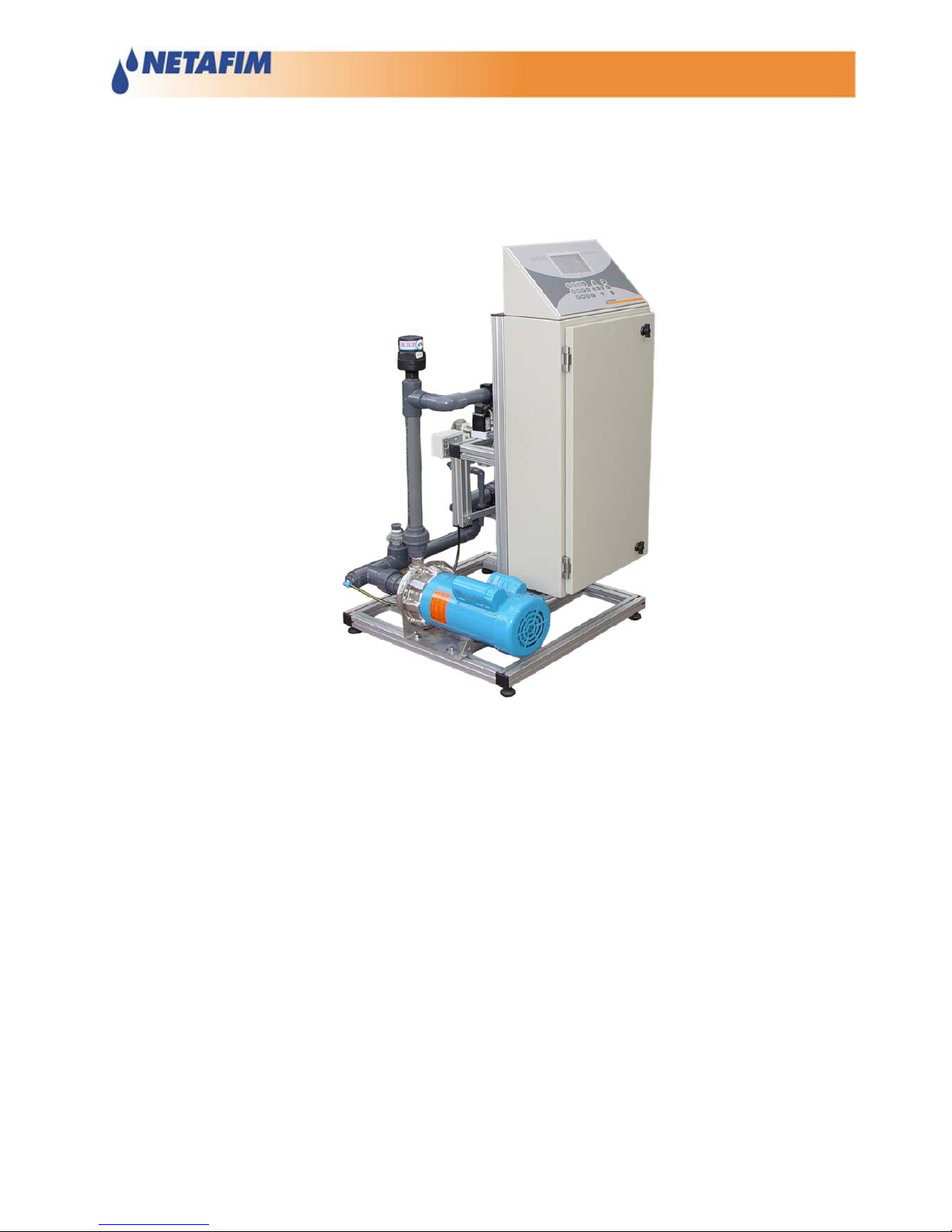
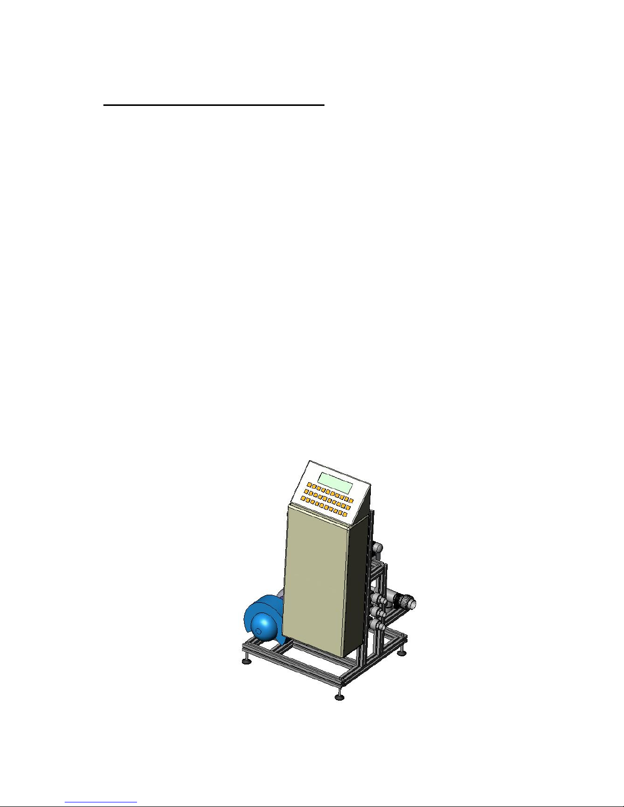
Schemes and Drawings:
Figure 2 - Netajet Front View
7
Page 8
NetaJet Dosing Unit
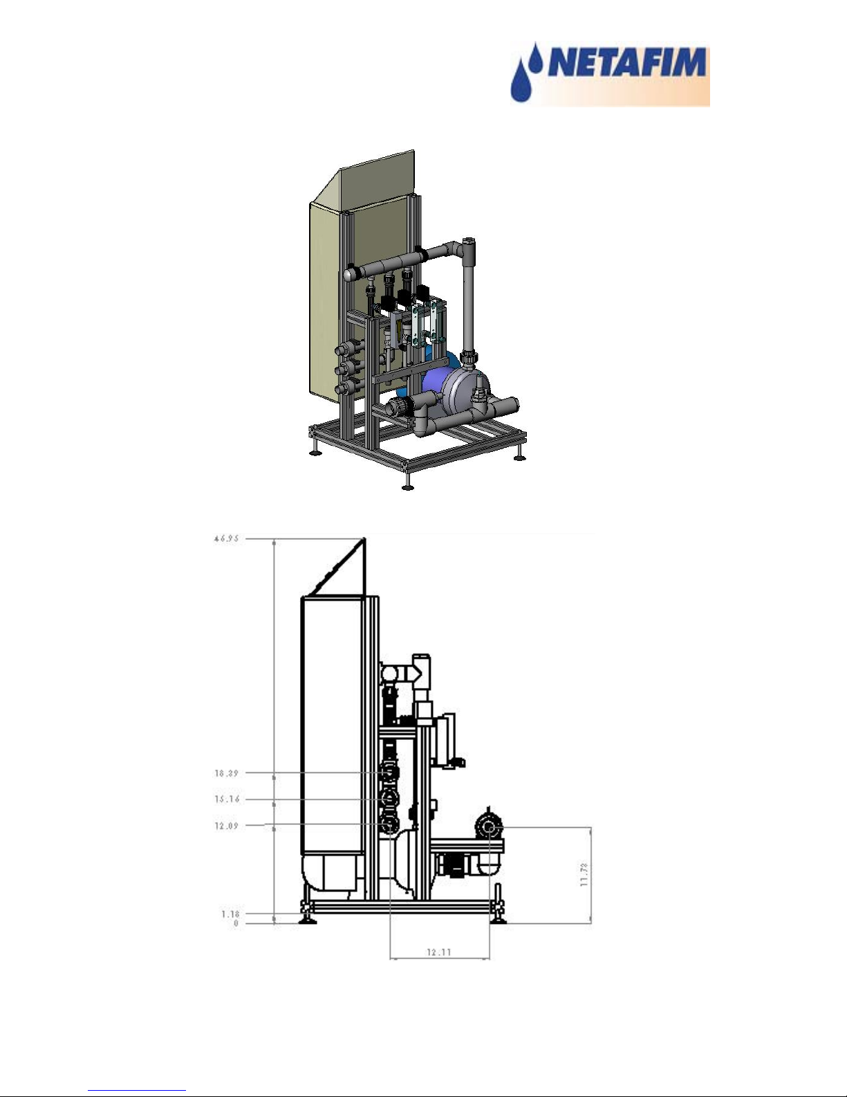
Figure 3 - Netajet Back View
Figure 3 – Side drawing (inches dimensions)
8
Page 9
NetaJet NMC User & Installation Manual Structure & Specifications
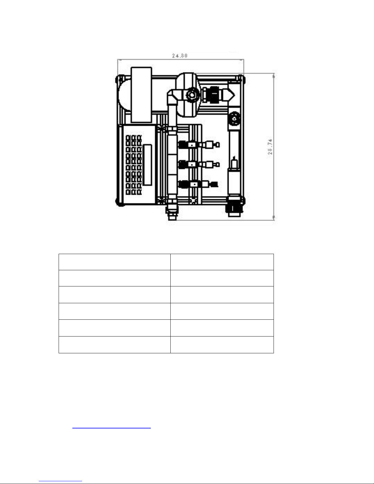
Figure 4 – Upper drawing (inches dimensions)
Inlet / Outlet Dimensions
Netajet
Inlet Diameter 1½ inch NPT male thread
Fertilizer A Outlet Diameter 1 inch NPT male thread
Fertilizer B Outlet Diameter 1 inch NPT male thread
Acid Outlet Diameter 1 inch NPT male thread
Fertilizers & Acid supply ½ inch BSP male thread
Water supply:
The supply water to the NetaJet has to be:
• No more than 72 PSI.
• No less than 30 PSI.
• Constant in terms of pressure (not fluctuating). If there are fluctuations of more than
10 PSI in supply water pressure, a pressure sustaining valve must be installed (see
Pressure sustaining valve).
9
Page 10

NetaJet Dosing Unit
Fertilizer dosing capacity
• Maximum dosage capacity will be achieve in the minimum operating pressure of 30
PSI (in the main line), at this pressure, the dosage capacity per fertilizer channel is
60 Gallon/hour and per acid channel is 15 Gallon/hour.
• The dosage capacity is virtually independent of the operating pressure above the
specified minimum 30 PSI.
• Minimum dosage capacity of a dosing channel is 10% of the maximum dosage
capacity.
• Maximum and minimum dosing capacity can be adjusted per channel via the pinvalve located on the visual flow meter.
• Motive flow per fertilizer channel is around 700 Gallon/h and per acid channel is
around 235 Gallon/hour.
Notice: Motive and Suction flow of the venturis depends in the inlet and outlet
pressure of the venturi (
see venturis table).
10
Page 11

NetaJet NMC User & Installation Manual Installation
Installation
This chapter details the hydraulic and electrical installation instructions for the Netajet
dosing unit. The aim of this chapter is to enable and assist technicians and skilled
growers to install and commission the Netajet dosing unit.
Environmental conditions
The Netajet dosing unit has been designed for installation in service room or a shaded
area.
When installing the complete dosing unit, including water supply, fertilizer tanks, etc’
the following rules must be observed:
1. Install the dosing unit in a shaded area and make sure that it is not exposed to
direct sunlight, especially the electrical cabinet.
2. Install the dosing unit in an area with an ambient temperature of between 40 °F and
105 °F and a maximum relative air humidity of 85 % (without condensation). Make
sure it is properly ventilated.
3. Install the dosing unit in a dry area protected from splashes, direct spraying with
water or chemicals.
4. The dosing unit must be installed on a hard, leveled floor.
5. Ensure that suitable electrical power supply is available in the vicinity of the
installation for connection of the Netajet dosing unit.
6. Ensure that there is an electrical socket available in the Netajet vicinity both for
installation and for maintenance.
11
Page 12

NetaJet Dosing Unit
Hydraulic installation
There are a few rules and recommendation that must observed when installing the
Netajet dosing units:
General requirements
Water supply
Prior to Netajet installation the following points must be observed and dealt with:
• Filtering:
An 80-mesh filter must be installed before the Netajet dosing unit. Moreover it is
recommended that a filter that removes solid contaminants of more than 500 µm
should be installed before the Netajet. This will significantly reduce the risk of
gradual build-up of contaminants in the area of the pH measurement, venturi inlets,
etc’ and will reduce the risk of malfunctions associated with this.
• Water temperature:
It is important to verify that the irrigation water temperature is always kept in the
allowed values of 40°
to 105° F.
• Chemical conditioning:
In case of high levels of bicarbonate concentrations in the supply water it will be
practically impossible to accurately control the pH levels, moreover there will be a
difference between the levels measured by the Netajet to the levels measured in the
field. In this case it is recommended to pre-treat the supply water by means of
acidification. Acid pre treatment of the water is only desirable if the
bicarbonate/"dissolved carbon dioxide" concentration is too high, then injecting acid
into a storage tank can solve the problem. The reaction of the acid with the
bicarbonate will result in the release of CO
2
. It is essential that the CO2 be properly
removed before the water is injected with the fertilizers to prevent it from taking part
in the chemical reactions.
• Pressure:
• Maximum 72 PSI.
• Minimum 30 PSI.
• Constant, not fluctuating; If there are fluctuations of more than 0.5 bar in
supply water pressure a pressure sustaining valve must be installed (see
Pressure sustaining valve)
• Suitable for field requirements.
Fertilizer supply:
• Fertilizer tanks:
In order to ensure maximum and even fertilizer capacity the following rules
must be observed:
12
Page 13

NetaJet NMC User & Installation Manual Installation
• The fertilizer tanks must be installed as close as possible to the Netajet. It is
recommended to keep a maximum pipe length of 10 meters. Nevertheless
there has to be enough space between the fertilizer tanks themselves and
between the Netajet so that inspection and maintenance operations can be
carried out.
• The fertilizer tanks must be at least the same level as Netajet if not higher.
• Piping and fittings for all dosing channels must be kept as similar as possible
in terms of dimensions and length.
• All supply lines for water and fertilizer and output lines for fertilizer and acid
can be plumbed using PVC (Schedule 80 preferred), Flexible PVC hose (must
be protected from UV radiation) or polyethylene hose.
• For acid, the supply lines are normally installed and maintained by the acid
supplier. Teflon is the best material for acid supply lines. PVC and Stainless
Steel are acceptable but have a shorter life. No nylon, brass, galvanized or
steel fittings can be used.
• It is recommended that the suction from the fertilizer tanks be done about 5-10
cm higher than the bottom of the tank. This prevents suction of sediment and
reduces the risk of clogging and blockage.
• Filtering:
It is essential to ensure proper filtering before the Netajet dosing channels; the
minimum filter should be of 120-mesh screen. All sand must be removed from the
water.
• Piping:
The hose connection of the Netajet is suitable for a ½ inch flexible hose. Make sure
the hose used is chemical resistant. It is recommended to tighten the hose with a
stainless steel hose clip.
NetaJet Installation Instructions
• The ratio between irrigation water flow / Bypass water flow should be no less than
1.5 and no more than 100. This is essential because of the solubility of the
fertilizers in the Bypass water flow
Flow through the NetaJet should be calculated as follows:
• Flow per fertilizer channel is around 760 Gallon/h (700 Gallon/h motive flow +
60 Gallon/h fertilizer suction).
• Flow per acid channel is around 250 Gallon/h (235 Gallon/h motive flow + 15
Gallon/h acid suction).
13
Page 14

NetaJet Dosing Unit
• A distance of about 6.5 foot should be maintained between inlet and outlet
connections of the NetaJet to the irrigation mainline (see drawing below).
• It is important to ensure proper turbulent flow between Bypass water and irrigation
water in the mainline. There are a few alternatives to achieve the required turbulent
flow, for example:
• Adding a mixing chamber such as a filter on the mainline (see
Figure 6 -
Installation with Filter)
• Adding an injection tube fitted in the inlet and outlets of the irrigation mainline.
• Typically pH adjusting flow is injected upstream of filtration and fertilizer is
downstream of filtration. If products are injected upstream of filtration the increased
flow must be included in filtration design for total flow as the NetaJet flow will be
filtered twice.
water
meter
5 D
6.5 ft
5 ft
Figure 5 - NetaJet Hydraulic Installation
14
Page 15

NetaJet NMC User & Installation Manual Installation
water
meter
5 D
ACID
FERT A
FERT B
Figure 6 - Installation with Filter
15
Page 16

NetaJet Dosing Unit
Typical installation
16
Page 17

NetaJet NMC User & Installation Manual Installation
17
Page 18

NetaJet Dosing Unit
Electrical and controller installation
Electrical Grounding
Electrical equipment can be destroyed or slowly damaged by voltage spikes, lightning
hits, etc’. Proper electrical grounding in combination with the NMC-64 internal
protections is essential to protect the system, reduce the risk of damage and prolong its
lifetime.
Correct selection and installation of equipment will protect your system and reduce the
risk of human injury.
Proper grounding provides an easy path for electrical current to return to its source.
A grounding system should tie all non-current carrying conductors to earth ground (0
volts). The grounding system should present a minimum resistance to current flow.
Make sure all items used are in proper condition, for example, a corroded wire clamp
attaching a ground wire to a ground rod might add 100 ohms or more resistance to a
system.
Less than 5 ohm will be considered as a good ground.
A very good ground needs to be supplied using a minimum of 2 grounding rods
and 4 Gauge standard wire connecting the grounds to the NetaJet.
Ground Rods
Ground rods are used to efficiently connect the system to earth where current may be
dissipated in the soil.
• Material:
Ground rods should be copper clad.
• Diameter:
Minimum 5/8”, preferably 3/4”. Generally the larger the rod diameter, the lower it’s
resistance to current flow.
• Length:
Minimum 8 feet, preferably 10 foot. A longer ground rod will reach a soil with higher
moisture content. Moist soil carries current much better than drier soil.
• Single grounding:
It is important that there is only one grounding location where a rod or series of rods
are connected to each other using a ground wire.
18
Page 19

NetaJet NMC User & Installation Manual Installation
Independent ground rods will increase the risk of current, from a lightning strike for
example, being dissipated through one rod and reentering the system through an
adjacent rod.
• Location;
Close to the main circuit breaker panel and in moist soil. For example in an area
that is usually wet from a drip or a low spot where water drains. Make sure the area
is well protected from damage by lawnmowers, tractors, etc’.
• Rod installation
Drive the rod into the earth until about 10 cm (4 inches) is left above grade. If it is
impossible to drive the rod to the proper depth, it is acceptable to lay the rod
horizontally, 2.5 feet below grade.
In case the rod is exposed to damage, for example by lawnmowers or tractors it can
be installed in a hole, about 8 inches deep so that the rod is about 0.3 feet under
grade and 0.3 feet above hole level.
Notice: The National Electric Code (NEC) mandates two ground rods unless you
can show less than 10 ohms resistance with one rod.
Ground Wire
The ground wire is a large copper wire that connects the main circuit breaker panel to
the ground rod.
• Diameter:
Typically, 6-gauge copper standard wire is sufficient. If the wire run is greater than
20 feet, 4 - gauge wire should be used.
The ground wire should be protected from damage by lawnmowers, tractors, etc’. It
should be buried minimum 6 inches under grade for protection and enter the house as
soon as possible. It is important that the wire not be cut; it should remain continuous.
Ground Clamps
Ground wires should not be merely wrapped around a ground rod. Ground clamps are
used to attach a ground wire to a ground rod. The most common clamp is known as an
acorn clamp.
Make sure the ground clamps you select are rated for outdoor use. Do not use pipe
clamps rated for inside water lines or hose clamps to attach the ground wire.
19
Page 20

NetaJet Dosing Unit
Ground connection
What Should Be Grounded?
Any equipment that is or could become energized, even accidentally, should be
grounded. Current from lightning, strikes objects in a random fashion. Accounts of
lightning strikes reveal scenarios most of us could not predict.
Electric circuits should be wired with a 3-wire conductor consisting of hot, neutral and
grounding wires. The grounding wire should be attached cleanly and securely to
devices or systems to be grounded. The other end of the grounding wire should be
attached to the ground bus on the main panel.
Supply power
Installer needs to supply power to NetaJet in conduit with disconnects. The NetaJet
includes power protection for the controller and motor controls for the motor.
Electrical connection to NetaJet divided per 2:
• Controller - 1Phase, 2 amps at 120 VAC with disconnect.
• Booster pump – 2 HP at 240 VAC or 480 VAC 3 phase (optional) with
disconnect.
Electrical connection – 2X240VAC
Main power
t
o
the Net
aJe
t
Supply power
to the NMC
controlle
r
Power to the
Booster pump
20
Page 21

NetaJet NMC User & Installation Manual Installation
Electrical connection – 3X480VAC
Pictures will be change
21
Page 22

NetaJet Dosing Unit
PH Transmitter & Sensor connection and calibration
Typically the pH transmitter will be supplied wired and connected to the NMC-64,
nevertheless it should be checked and calibrated after system installation.
Connecting pH sensor to Transmitter:
1. Connect wire (HI) to connector 10.
2. Connect shield (LO) to connector 11.
Warning!
•
Do not remove resistors from connectors 3-4 and 5-6.
• Do not switch between shield and wire connections.
• Do not connect/press “wire ends” on the sensor’s cable.
pH Transmitter Calibration
The calibration procedure requires calibration fluids of two levels, the recommended
values are: pH 7 for the high-level calibration fluid and pH 4 for the low-level calibration
fluid. If calibration fluids of these values are not available other calibration values can
be used.
1. Remove the sensor from its socket and wipe fluids off it.
2. Insert the sensor into the higher-level calibration fluid, for instance with a pH value
of 7 (Milwaukee pH 7.01 buffer).
3. Using the ZERO (and according to measured temp) adjust the reading to fit the pH
value as on the calibration fluid (example – if temp is 25C°, the pH value shall be
7.01).
4. Wipe the sensor and insert it to the lower value calibration fluid, for instance with pH
4 (Milwaukee pH 4.01 buffer). Keep the sensor in the buffer for 1 minute before
starting calibrate.
5. Calibrate with the SENS until the pH reading is as on the calibration fluid, according
to 25
o
C (example – using 4.01 buffer and temp is 25C°, the pH value shall be 4.01).
6. Carefully insert the sensor back to its socket.
7. Repeat sensor calibration every two weeks.
Warning!
The pH should not be dry, make sure to put it in fluid immediately after calibrating.
22
Page 23

NetaJet NMC User & Installation Manual Installation
Allowing the PH sensor to dry out, will damage and is not covered by warenty.
Connecting pH transmitter to NMC-64 controller
1. Connect pH transmitter to NMC-64 analog input card as follows:
2. pH transmitter’s connector 1 to analog card’s connector Red.
3. pH transmitter’s connector 2 to analog card’s connector T6.
4. Check that analog card’s jumper 2 (from left) is set to 4-20mA.
Figure 7 – pH sensor & transmitter’s connections to Analog input card
23
Page 24

NetaJet Dosing Unit
EC Transmitter & Sensor connection and calibration
Typically the EC transmitter will be supplied wired and connected to the NMC-64
(if ordered as option), nevertheless it should be checked and calibrated after system
installation.
Connecting EC sensor to Transmitter:
1. Remove resistors from connectors 3-4 and 5-6.
2. Connect Green wire to connector 4.
3. Connect Red wire to connectors 5 and 6.
4. Connect Black wire to connectors 10 and 11.
5. Connect White wire to connectors 12 and 13.
6. Adjust the Dip-switches (white ON) as follow:
EC Transmitter Calibration
1. Remove the sensor from its socket and wipe fluids off it.
2. Using the ZERO, bring the reading to 0 (no calibration fluid is needed here).
3. Insert the sensor into the calibration fluid (Milwaukee 1413 µS/cm solution).
4. Calibrate with the SENS until the EC reading is as on the calibration fluid and
according to 25
o
(example – using Milwaukee 1413 µS/cm solution transmitter
should be calibrated to show a value of 1.41 mS).
5. Insert the sensor back to the socket and tighten it.
6. Repeat sensor calibration once every two months.
Connecting EC transmitter to NMC-64 controller
1. Connect EC transmitter to NMC-64 analog input card as follows:
2. EC transmitter’s connector 1 to analog card’s connector Red.
3. EC transmitter’s connector 2 to analog card’s connector T5.
4. Check that analog card’s jumper 1 (from left) is set to 4-20mA.
24
Page 25

NetaJet NMC User & Installation Manual Installation
12VDC
Red
Inpu
t
2
1
Figure 8 – EC sensor & transmitter’s connections to Analog input card
25
Page 26

NetaJet Dosing Unit
NMC-64 EC & pH definitions and calibration
1. Menu 8.2 - Install / Analog Input 1:
Define pH sensor No. 1 on input number 6.
2. Menu 7.7 - CONFIGURATION / EC pH SENSOR RANGE:
Define table as follows:
Sensor 4 mA 20 mA
EC (Ms) 0 20
pH 0 14
3. Menu 6.6 - SETUP / EC pH CALIBRATION:
Change factor by pressing on the right and left arrows until value displayed on
controller screen is identical to the value displayed on transmitter screen:
Sensor Value Factor
EC 1.41 0.00
pH 7.00 0.00
26
Page 27

NetaJet NMC User & Installation Manual Installation
NNM-64 Installation - Getting started
This paragraph briefly explains how to get started with the NMC-64 software setup
procedure. For further explanations please refer to the NMC-64 User & Installation
Manual.
For initial configuration of the controller start with Menu 6: Setup.
Later steps might depend on earlier ones; therefore it is essential to go through all the
steps.
You can use the following chart for assistance.
Table # Table description NMC-64
Setup
6.1 Time & date Set your local Time and Date
6.2 System Setup Define system definitions such as measurement
units, PC communication etc’.
Installation
8.1 Device Definition Define which devices are needed in you application.
8.2 Device Layout Assign an output (Relay) to each device.
8.3 Analog Input Assign inputs to analog sensors, for example
EC/pH, temp sensors etc’.
8.5 Digital Input Assign inputs to digital sensors, for example water
meters, Dry contact, etc’.
Configuration
7.1 Pump Valve Delay Choose whether to start first with pump or valve and
define operation order.
7.2 Valve Configuration Configure a valve to a pump, mainline and water
meter. .
7.3 Valve Flow Rate Define valve flow rate.
7.4 Water meter Define volume per pulse of the water meter.
7.5 Fertilizer Setting Define fertilizer channel definitions; pump type,
operation method, ratio etc’.
27
Page 28

NetaJet Dosing Unit
7.6 EC/pH Setting Define whether fertigation is according to EC/pH
and set injection definitions.
Table # Table description NMC64
Setup
6.6 EC PH calibration Adjust the calibration factor so that the Value is
similar to the value shown on the EC&pH
transmitters
Test
5.1 Relays Verify the functionality of each output/device.
Program
1.2 Run Time program Define water programs; method (quantity/time),
total water quantity/time, water before and
water after.
Notice: water before/after are deducted from
total water quantity/time.
1.3 Fertilizer Program Define fertilizer programs; method (proportional
quantity/time, total quantity/time), quantities/time
per channel and EC/pH set points.
1.1 Irrigation Program Define irrigation program; start times, number of
cycles, time between cycles, participant valves,
run-time programs, fertilizer program, etc’.
Manual start
2.3 Manual Start Valve Manually start each valve and verify that the set
nominal flow rate is similar to the measured one.
2.2 Manual Start Program Manually start the programs to check whether
they are operative as set/expected. The
program can manually be shut down after
proper operation has been verified.
For detailed explanations please refer to NMC-64 User & Installation Manual.
28
Page 29

NetaJet NMC User & Installation Manual Installation
NetaJet Commissioning
When commissioning the NetaJet, keep to the following procedure:
• Ensure that the outlet of the NetaJet to the water distribution system is closed;
• Fully bleed the NetaJet pump. The pump must not run dry. Consult the pump
supplier's documentation for how to bleed the pump.
• Open the NetaJet switch box and start the NetaJet pump manually (see below in
this paragraph on how to start the NetaJet manually);
• Verify that the NetaJet pump is rotating in the correct direction (see arrow on pump
casing).
• Check the pressure in the venturi with the pressure gauge on the NetaJet. When the
NetaJet outlet for the water distribution is closed, the pressure must agree with the
value indicated in the documentation for the NetaJet pump;
• Ensure that the fertiliser lines are filled completely with fertiliser up to the venturis;
When commissioning is concluded, clean the filter on the NetaJet running
towards the EC tubes and the venturis
29
Page 30

NetaJet Dosing Unit
Installation requirements
Pressure sustaining valve
The pressure sustaining valve is used to ensure that the NetaJet works against
constant pressure and should be added to the system whenever the mainline pressure
fluctuates more than 0.5 bars.
The pressure sustaining valve (PSV) is installed on the main line after the NetaJet inlet
and ensures the pressure doesn’t drop below the set value.
Install that PSV on the mainline after the NetaJet.
1. Check the maximum pressure on the main line, this can be done by making sure all
pumps are operative and opening the smallest crop section to be irrigated at once.
In case the water supply is from a municipal source or a source that supplies to a
few systems at once make sure you check the pressure when the pressure is
maximal, this will usually be when a minimal number of consumers are operative.
2. Calibrate the PSV so that it maintains a pressure that is 3-4 meters higher than the
maximal pressure measured on the mainline.
PSV
Inlet valve
(Optional)
Figure 11 - PSV Installation
30
Page 31

NetaJet NMC User & Installation Manual Installation
Maintenance
In order to ensure reliable and optimal operation and extend system life cycle regular
maintenance must be cried out.
The NetaJet dosing unit and its immediate environment must be kept clean by
removing dust, water and chemicals from the dosing unit. It is important that all filter
elements on and in the vicinity of the NetaJet are cleaned regularly.
The NetaJet, supply water and irrigation water system must be checked regularly for
leaks, air bubbles in fertilizer and/acid/alkali lines and the pump pressure.
Description How often See link
PH sensor calibration Every 2 –4 weeks
EC sensor calibration Every 2 months
Fertilizer filters cleaning Once a week
Supply water filters cleaning Once a week
Leak inspection Once a week
Winterization:
• Pump draining
• PH & EC sensors
• Plumbing drain
31
Page 32

NetaJet Dosing Unit
Parts list & Description
Item Description Netafim serial # USA Part #
1 Goulds Pump N/A
2 Switch Board N/A
3 Controller’s display N/A
4 Aluminum frame 45000-008740
5 Half union 50
Adaptor nipple 50x1½”
77300-019660
77300-012200
6 EC&PH inlet manifold 33000-005550
7 Geka PVC connector 3/4" Male
Geka PVC connector 3/4" Female
77300-022700
77300-022800
8 Half union 50
Adaptor nipple 50x1¼”
77300-019660
77300-012100
9 Half union 40
Adaptor nipple 40x1”
77300-019950
77300-013600
10 Upper manifold 33000-005600
11 Acid outlet 33000-005650
12 Fertilizer B outlet 33000-005700
13 Fertilizer A outlet 33000-005750
14 1” Rubber washer 77300-029200
15 3/4” Rubber washer 77300-003050
16 Adaptor nipple ¼” x ¾” 77300-022600
17 Half union for dosing valve 77300-011550
77300-021400
18 Half union (Nut) for dosing valve 77300-021100
19 Burkert dosing valve, type 124 77800-004000
20 Nipple ¼” x ¼” 77300-011200
32
Page 33

NetaJet NMC User & Installation Manual Installation
21 Inlet unit for Fertilizers and Acid
channels
33000-005800
22 Glass flow meter for Acid channel 77540-008300
23 Flow meter for fertilizer channel 77540-007500
24 EC sensor (optional) 45000-006660
25 PH sensor 45000-006680
26 Tube clip 50mm = 2” 77300-024300
27 Tube clip 32mm = 1¼” 77300-024150
28 Tube clip 40mm = 1½” 77300-024200
29 Mazzei injector 878 1”, 60 Gallon/hour 77800-003470
30 Mazzei injector 484-A ¾”, 15 Gallon/hour 77800-003450
31 Tube clip 16mm 77300 - 024000
33
Page 34

NetaJet Dosing Unit
Figure 12 – Service parts
34
Page 35

NetaJet NMC User & Installation Manual Installation
Venturis & Booster Pump Specifications
Water Suction Capacity – Injector Inlet Pressure 5 – 50 PSI
* Number in parenthesis indicate the injector outlet pressure when suction stop (Zero Suction Point)
35
Page 36

NetaJet Dosing Unit
Water Suction Capacity – Injector Inlet Pressure 60 – 120 PSI
* Number in parenthesis indicate the injector outlet pressure when suction stop (Zero Suction Point)
36
Page 37

NetaJet NMC User & Installation Manual Installation
Goulds Pump – Model NPE
37
Page 38

NetaJet Dosing Unit
D2
D3
D4
D1
H 1
H 2
H 3
Dimensions and weight
System type D 1
[Inch]
D 2
[Inch]
D 3
[Inch]
D 4
[Inch]
H 1
[Inch]
H 2
[Inch]
H 3
[Inch]
NetaJet NMC 1 ½ 1 1 1 46.95 28.34 24.8
System type Package Net weight (lb) Gross weight (lb)
NetaJet NMC
38
Page 39

NetaJet NMC User & Installation Manual Installation
Tips for calibrations
Before running the NetaJet, a calculation has to be done in order to understand what
are the dosing capabilities.
The following data is part of the calibration process and has to be consider before the
system operation:
• Minimum and Maximum flow rate that required from the field.
• Suction capacity of each venturi which is influenced by the pressures around the
system.
• Fertilizers concentrations which is influence on the EC value of the irrigated
water.
Example A: System calculation according a specific case
Data:
Flow rate demand from the field: 1500 Gallon/min
Fertilizer injection capacity: 60 Gallon/hour =
mi
n
60
/60 hourGallon
= 1 Gallon/min
Acid injection capacity: 15 Gallon/hour =
mi
n
60
/15 hourGallon
= 0.25 Gallon/min
Calculation:
Fertilizer injection capacity
Maximum quantity that can be delivered by a fertilizer channel:
mi
n
/
1500
min/1
Gallon
Gallon
=
Main line capacity
Gallon
Gallon
1500
1
Gallon
Gallon
X
Gallon
Gallon
1000
67.0
1000
1500
1
=
This formula is demonstrate how to calculate the higher limit of a fertilizer channel,
means when the NMC controller will open the Dosing Valve for 100% the NetaJet
will inject 0.67 Gallon from the fertilizer channel to every 1000 Gallons of water that
flows through the main line to the field.
39
Page 40

NetaJet Dosing Unit
The same calculation can be done for the acid channel:
Acid injection capacity
Maximum quantity that can be delivered by an acid channel:
=
mi
n
/
1500
min/25.0
Gallon
Gallon
Main line capacity
Gallon
Gallon
1500
25.0
1000
1500
25.0
X
Gallon
Gallon
=
Gallon
Gallon
1000
17.0
Example B: Ec calibration according the system capabilities
After the calculations in Example A, Ec definition can be done as follow:
Data:
Maximum quantity of fertilizers that can be delivered by the NetaJet per every 1000
Gallons of water that flows through the main line to the field:
0.67 X 2 channels = 1.34 Gallon
Because Ec reaction is linear, the following procedure can be implement in order to
know the Ec value that will be reached after the NetaJet:
0.67 Gallon = 86 Ounce
• Take sample of 86 ounce from each fertilizer tank and mix it in sample of 1
Gallon from the water source.
• Measured by Ec meter the Ec value of the mixed solution.
This is the maximum Ec that will be achieved according to the examples above.
TANK B
86 Ounce 86 Ounce
TANK A
1 Gallon
When the fertigation process is done by the proportional quantity method, always
keep a difference to be able to make corrections up or down in order to control the
Ec value.
40
Page 41

NetaJet NMC User & Installation Manual Installation
The recommended value is between 50% - 70% of the fertilizer channel limitation,
means: 0.67 X 70% = 0.47 Gallon of fertilizer from each channel to be inject per
1000 Gallons that flows through the main line.
Notice: Do not use too concentrated fertilizers in order to achieve a higher Ec
value, using too concentrated fertilizers can bloke the injectors (venturies) because
of solidification.
41
Page 42

NetaJet Dosing Unit
Warranty and safety
Safety instructions
This chapter describes the safety instructions that should be applied when installing,
using and maintaining all NetaJet dosing units.
Installation and maintenance
The dosing unit must always be switched off before installation or maintenance work
is carried out on it.
If installation work has to be carried out on the supply, the lighting circuit group to
which the dosing unit has been or is connected must first be isolated from the
supply.
Preparing the stock of acid/lye
Observe the following rules when working with acids:
• Protect your eyes: wear safety goggles!
• Never add water to acid or lye, but always acid to water! This is because of the
large amount of heat developed and the danger of acid splashes when you add
water to acid.
• Never allow water to back flow or enter acid tank. This will cause a severe reaction
and possibly melt the acid holding tank if it is made of plastic.
42
 Loading...