

Page 1

V 002.01 - JULY 2017
MEGANET
TM
USER MANUAL
ROTATING IMPACT
SPRINKLER
Page 2

© COPYRIGHT 2016, NETAFIM™
NO PARTS OF THIS PUBLICATION MAY BE REPRODUCED, STORED IN AN AUTOMATED DATA FILE OR MADE PUBLIC IN
ANY FORM OR BY ANY MEANS, WHETHER ELECTRONIC, MECHANICAL, BY PHOTOCOPYING, RECORDING OR IN ANY
OTHER MANNER WITHOUT PRIOR WRIT TEN PERMISSION OF THE PUBLISHER.
ALTHOUGH NETAFIM™ TAKES THE GREATEST POSSIBLE CARE IN DESIGNING AND PRODUCING BOTH ITS PRODUCTS
AND THE ASSOCIATED DOCUMENTATION, THEY MAY STILL INCLUDE FAULTS.
NETAFIM™ WILL NOT ACCEPT RESPONSIBILIT Y FOR DAMAGE RESULTING FROM USE OF NETAFIM'S PRODUCTS OR
USE OF THIS MANUAL.
NETAFIM™ RESERVES THE RIGHT TO MAKE CHANGES AND IMPROVEMENTS TO ITS PRODUCTS AND/OR THE
ASSOCIATED DOCUMENTATION WITHOUT PRIOR NOTICE.
FOREIGN LANGUAGES
If you are reading this manual in a language other than the English language, you acknowledge and
agree that the English language version shall prevail in any case of inconsistency or contradiction in
interpretation or translation.
NOTE
All the drawings in this document are for the purpose of illustration only. The actual product details
and infrastructure condition may differ in any actual application.
Page 3

CONTENTS
Introduction
Use of symbols
Aim of this manual
Safety instructions
MegaNet™ rotating impact sprinkler
Description
Applications
Features and benefits
Specifications
Technical data
Performance
Max. lateral length - 10% flow variation
Sprinkler water trajectory
Head loss in riser tube
Installation
Introduction
Various installation configurations
Maintenance
Rinsing the filter
Checking the turbine and the cover
Cleaning the nozzle
Parts and complementary products
Parts
Complementary products
Models for specific uses
Appendix 1: Special applications
Special model for cement connection
Special model with anti-drain valve
Adding a PRV
Road protector
Warranty
4
4
4
5
5
5
6
7
9
11
11
12
12
13
14
15
17
18
19
20
21
21
22
23
Page 4

4
MegaNet
TM
USER MANUAL
INTRODUCTION
WARNING
The following text contains instructions aimed at preventing bodily injury or direct damage to
the crops, the product and/or the infrastructure.
CAUTION
The following text contains instructions aimed at preventing unwanted system operation,
installation or conditions that, if not followed, might void the warranty.
ATTENTION
The following text contains instructions aimed at enhancing the effective use of the instructions
in the manual.
NOTE
The following text contains instructions aimed at emphasizing certain aspects of the installation
or operation of the product.
SAFETY FOOTWEAR
The following text contains instructions aimed at preventing foot injury.
TIP
The following text provides clarification, tips or useful information.
Use of symbols
The symbols used in this manual refer to the following:
Aim of this manual
The aim of this manual is to guide the user in setting up, installation, operaton and maintenance of the
MegaNet™ sprinkler in its various applications.
Safety instructions
• All applicable safety instructions and regulations must be observed and applied.
• The effectiveness of the equipment may be jeopardized or impaired if the equipment is used in a manner
other than that specified by the manufacturer.
WARNING
In an agricultural environment - always wear protective footwear.
CAUTION
When opening or closing any manual valve, always do so gradually, to prevent damage to the
system by water hammer.
Page 5

MegaNetTM USER MANUAL
5
MEGANET™ ROTATING IMPACT SPRINKLER
Description
Applications
High water trajectory angle - 24D
- for vegetables and open field crops, open field nurseries,
crops germination, frost mitigation, cooling fruit orchards and roof dust cleaning.
Low water trajectory angle - 15D
- for under-tree irrigation and shade/net houses.
Features and benefits
Ensures high and uniform yield
• The MegaNet™ has a symmetrical structure that splits the water into two equal jets. That
contributes to the balanced of the sprinkler, providing very high water distribution uniformity.
Increased germination percentage
• Thanks to the gentle water jet, and relatively small drops near the ground, the MegaNet™ does not
groove the soil along the whole irrigation event (including startup and shut off), which prevents the
seeds from being exposed - out of the soil.
Reduced maintenance cost
• The MegaNet™ has a popup mechanism that opens only during irrigation, this mechanism protects
the nozzle and protects the sprinkler's moving parts by preventing insects and dirt particles from getting
inside the sprinkler.
• Each MegaNet™ sprinkler has an integral filter that ensures clean water inside the nozzle. In addition,
this filter can be easily cleaned if needed.
• Extended product life achieved by superior raw material composition resistant the chemicals, fertilizers,
and exposure to sunlight.
Cover
Base
Upper
body
½" male thread
Pin
Cement connector Non-leakage valve
Thread connector model Cement connector model
ISO C 20 mm / ASTM C ½"
Thread connector model
with non-leakage valve
Page 6

6
MegaNet
TM
USER MANUAL
MEGANET™ ROTATING IMPACT SPRINKLER
Specifications
• 7 different nominal flow rates: 200, 250, 350, 450, 550, 650, 750 l/h.
Nominal flow rates at 2.3 bar pressure.
• Recommended working pressure: 2.0 to 3.0 bar (at the sprinkler head).
• Can be installed on solid sets or in removable field stands.
• Made of UV-protected materials, durable to all climate conditions and nutrients injected in agricultural
applications
• 2 types of water trajectory:
• High, 24 degrees
• Low, 15 degrees
• Inlet connector:
• 1/2" Threaded inlet connector
• 20 MM ISO inlet connector (to be glued to PVC)
• 1/2" ASTM inlet connector (to be glued to PVC)
• Code-colored locking pins and caps for easy identification.
• 2 balanced water jets.
• Individual filter in each sprinkler.
• MegaNet™ sprinklers meet ISO 8026 standards (SI 1406) with production certified by the
Israel Standards Institute (SII).
• Recommended filtration: 400 micron / 40 mesh.
Selection of the filtration method should be based on the kind and concentration of dirt particles in the
water.
ATTENTION
• For water containing over 2 ppm of sand, a hydrocyclone sand separator must be installed
upstream from the main filter.
• For water containing over 100 ppm of sand/silt/clay solids, pretreatment must be performed
according to the instructions of the Netafim™ expert team.
Page 7

MegaNetTM USER MANUAL
7
TECHNICAL DATA
Performance
Rectangular spacing
MegaNet™ 15D
Water trajectory angle: 15 degrees. Pin color code: Gray
Nozzle
size
(mm)
Color
code
Working
pressure
(bar)
Flow
rate
(l/h)
Wetted
diameter
*
(m)
Spacing - rectangular (m x m)
7 x 8 8 x 8 9 x 8 10 x 8 9 x 9 9 x 10 10 x 10
Precipitation rate (mm/h)
2.44 Green
2.5 362
14
6.4 5.6 5.0 4.5 4.4 4.0 3.6
3.0 396 7.1 6.2 5.5 5.0 4.9 4.4 4.0
2.79 Blue
2.5 461
16
8.3 7.2 6.4 5.8 5.7 5.1 4.6
3.0 505 9.0 7. 9 7.0 6.3 6.2 5.6 5.0
3.08 Brown
2.5 553
16
9.9 8.6 7.7 6.9 6.8 6.1 5.5
3.0 605 10.8 9.5 8.4 7.6 7. 5 6.7 6.1
3.37 Orange
2.5 678
16
12.1 10.6 9.4 8.5 8.4 7. 5 6.8
3.0 74 3 13.3 11.6 10.3 9.3 9.2 8.3 7. 4
3.68 Red
2.5 785
17
14.0 12.3 10. 9 9.8 9.7 8.7 7. 9
3.0 860 15.3 13.4 11. 9 10.7 10.6 9.5 8.6
* Performance table prepared under laboratory conditions, sprinkler head 0.5 meter above ground.
At least 0.5 mm/h.
MegaNet™ 24D
Water trajectory angle: 24 degrees. Pin color code: Black
Nozzle
size
(mm)
Color
code
Working
pressure
(bar)
Flow
rate
(l/h)
Wetted
diameter
*
(m)
Spacing - rectangular (m x m)
7 x 8 8 x 8 8 x 10 9 x 9 10 x 10 10 x 11 10 x 12
Precipitation rate (mm/h)
1.85 Yell ow
2.5 210
11
3.6 3.3
3.0 230 3.8 3.6
2.06 Purple
2.5 258
12
4.4 4.0
3.0 283 4.8 4.4
2.44 Green
2.5 362
14
5.9 5.6 4.5 4.4 3.6
3.0 396 6.5 6.2 5.0 4.9 4.0
2.79 Blue
2.5 461
17
8.1 7. 2 5.8 5.7 4.6 4.2 3.9
3.0 505 8.7 7. 9 6.3 6.2 5.0 4.6 4.2
3.08 Brown
2.5 553
18
10.0 8.6 6.9 7. 2 5.5 5.0 4.6
3.0 605 10 .1 9.5 7.6 7. 5 6 .1 5.5 5.1
3.37 Orange
2.5 678
18
11. 5 10.6 8.5 8.4 6.8 6.2 5.7
3.0 74 3 12. 3 11. 6 9.3 9.2 7. 4 6.8 6.2
3.68 Red
2.5 785
18
13.4 12. 3 9.8 9.7 7. 9 7.1 6.6
3.0 860
19
15.0 13. 4 10.7 10.6 8.6 7. 8 7.2
* Performance table prepared under laboratory conditions, sprinkler head 1.0 meter above ground.
At least 0.5 mm/h.
%CU
≥ 92% ≥ 88% and < 92% ≥ 86% and < 88% < 86%
(a)
(b)
Sprinkler
Lateral
* Nominal flow rate at 2.3 bar working pressure.
**Sprinkler height above ground: 15D = 0.5 m, 24D = 1.0 m. At least 0.5 mm/h.
Page 8

8
MegaNet
TM
USER MANUAL
Performance (cont'd)
Triangular spacing - isosceles**
MegaNet™ 15D
Water trajectory angle: 15 degrees. Pin color code: Gray
Nozzle
size
(mm)
Color
code
Working
pressure
(bar)
Flow
rate
(l/h)
Wetted
diameter
*
(m)
Spacing - triangular (m x m)
7 x 8 8 x 8 9 x 8 10 x 8 9 x 9 9 x 10 10 x 10
Precipitation rate (mm/h)
2.44 Green
2.5 362
14
6.4 5.6 5.0 4.5 4.4 4.0 3.6
3.0 396 7.1 6.2 5.5 5.0 4.9 4.4 4.0
2.79 Blue
2.5 461
16
8.3 7.2 6.4 5.8 5.7 5.1 4.6
3.0 505 9.0 7. 9 7.0 6.3 6.2 5.6 5.0
3.08 Brown
2.5 553
16
9.9 8.6 7.7 6.9 6.8 6.1 5.5
3.0 605 10.8 9.5 8.4 7.6 7. 5 6.7 6.1
3.37 Orange
2.5 678
16
12.1 10.6 9.4
3.0 74 3 13.3 11.6 10.3
3.68 Red
2.5 785
17
14.0 12. 3 10.9 9.8 9.7 8.7
3.0 860 15.3 13.4 11.9 10.7 10.6 9.5
* Performance table prepared under laboratory conditions, sprinkler head 0.5 meter above ground.
At least 0.5 mm/h.
MegaNet™ 24D
Water trajectory angle: 24 degrees. Pin color code: Black
Nozzle
size
(mm)
Color
code
Working
pressure
(bar)
Flow
rate
(l/h)
Wetted
diameter
*
(m)
Spacing - triangular (m x m)
7 x 8 8 x 8 8 x 10 9 x 9 10 x 10 10 x 11 10 x 12
Precipitation rate (mm/h)
1.85 Yell ow
2.5 210
11
3.6 3.3
3.0 230 3.8 3.6
2.06 Purple
2.5 258
12
4.4 4.0
3.0 283 4.8 4.4
2.44 Green
2.5 362
14
5.9 5.6 4.5 4.4 3.6
3.0 396 6.5 6.2 5.0 4.9 4.0
2.79 Blue
2.5 461
17
8.1 7. 2 5.8 5.7 4.6 4.2 3.9
3.0 505 8.7 7. 9 6.3 6.2 5.0 4.6 4.2
3.08 Brown
2.5 553
18
10.0 8.6 6.9 7. 2 5.5 5.0 4.6
3.0 605 10 .1 9.5 7.6 7. 5 6 .1 5.5 5.1
3.37 Orange
2.5 678
18
11. 5 10.6 8.5 8.4 6.8 6.2 5.7
3.0 74 3 12. 3 11. 6 9.3 9.2 7. 4 6.8 6.2
3.68 Red
2.5 785
18 13.4 12. 3 9.8 9.7 7. 9 7.1 6.6
3.0 860
19
15.0 13. 4 10.7 10.6 8.6 7. 8 7.2
* Performance table prepared under laboratory conditions, sprinkler head 1.0 meter above ground.
At least 0.5 mm/h.
**Do not confound isosceles with equilateral:
• An isosceles triangle is a triangle in which two sides are of equal length. The distance between 2
adjacent sprinklers on the same lateral (a) is not equal to the distance between 2 sprinklers on adjacent
laterals. The height of the triangle represents the distance between adjacent laterals (b).
Isosceles is usually referred to in open-field applications.
• An equilateral triangle is a triangle in which all three sides are equal. The distance between 2 adjacent
sprinklers on the same lateral is equal to the distance between 2 sprinklers on adjacent laterals.
Equilateral is occasionally referred to in orchards due to the tree planting pattern.
(a)
(b)
Sprinkler
Lateral
%CU
≥ 92% ≥ 88% and < 92% ≥ 86% and < 88% < 86%
TECHNICAL DATA
Page 9

MegaNetTM USER MANUAL
9
TECHNICAL DATA
Slope
Distance between sprinklers (m)
6 7 8 9 10
Max. lateral length (m)
Uphill
2% 102 112 120 126 140
1% 108 119 128 14 4 150
Flat terrain 0 120 133 144 153 170
Downhill
-1% 126 140 152 171 180
-2% 132 147 160 180 190
Nominal
flow rate:
200 l/h*
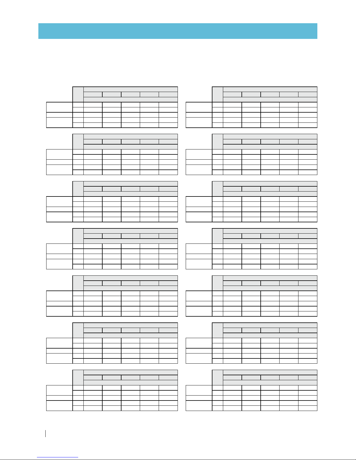
Max. lateral length - 10% flow variation
Inlet pressure: 3.0 bar
Lateral: PE 32 mm ID: 27.2 mm Lateral: PE 40 mm ID: 36.8 mm
Slope
Distance between sprinklers (m)
6 7 8 9 10
Max. lateral length (m)
Uphill
2% 90 98 112 117 120
1% 96 10 5 120 126 13 0
Flat terrain 0 102 119 12 8 135 150
Downhill
-1% 10 8 126 136 144 160
-2% 114 126 14 4 15 3 17 0
Nominal
flow rate:
250 l/h*
Slope
Distance between sprinklers (m)
6 7 8 9 10
Max. lateral length (m)
Uphill
2% 78 84 88 99 100
1% 84 91 96 108 11 0
Flat terrain 0 84 98 10 4 108 120
Downhill
-1% 90 98 112 117 130
-2% 96 105 112 126 130
Nominal
flow rate:
350 l/h*
Slope
Distance between sprinklers (m)
6 7 8 9 10
Max. lateral length (m)
Uphill
2% 66 77 80 90 90
1% 72 77 88 90 100
Flat terrain 0 72 84 88 99 100
Downhill
-1% 78 84 96 99 11 0
-2% 78 91 96 108 120
Nominal
flow rate:
450 l/h*
Slope
Distance between sprinklers (m)
6 7 8 9 10
Max. lateral length (m)
Uphill
2% 60 70 72 81 80
1% 66 70 80 81 90
Flat terrain 0 66 77 80 90 90
Downhill
-1% 72 77 88 90 100
-2% 72 77 88 99 10 0
Nominal
flow rate:
550 l/h*
Slope
Distance between sprinklers (m)
6 7 8 9 10
Max. lateral length (m)
Uphill
2% 54 63 64 72 80
1% 60 63 72 72 80
Flat terrain 0 60 63 72 81 80
Downhill
-1% 60 70 72 81 90
-2% 60 70 80 81 90
Nominal
flow rate:
650 l/h*
Slope
Distance between sprinklers (m)
6 7 8 9 10
Max. lateral length (m)
Uphill
2% 54 56 64 63 70
1% 54 56 64 72 70
Flat terrain 0 54 63 64 72 80
Downhill
-1% 54 63 72 72 80
-2% 60 63 72 81 80
Nominal
flow rate:
750 l/h*
Slope
Distance between sprinklers (m)
6 7 8 9 10
Max. lateral length (m)
Uphill
2% 15 0 161 176 180 190
1% 174 189 200 216 230
Flat terrain 0 198 217 240 252 270
Downhill
-1% 216 238 264 288 310
-2% 234 259 288 315 340
Nominal
flow rate:
200 l/h*
Slope
Distance between sprinklers (m)
6 7 8 9 10
Max. lateral length (m)
Uphill
2% 13 8 147 160 171 18 0
1% 15 6 168 184 198 210
Flat terrain 0 174 189 208 225 240
Downhill
-1% 18 6 210 232 252 270
-2% 204 224 248 270 290
Nominal
flow rate:
250 l/h*
Slope
Distance between sprinklers (m)
6 7 8 9 10
Max. lateral length (m)
Uphill
2% 120 12 6 13 6 14 4 150
1% 12 6 14 0 152 162 170
Flat terrain 0 138 154 168 180 200
Downhill
-1% 150 168 184 198 220
-2% 162 17 5 200 216 230
Nominal
flow rate:
350 l/h*
Slope
Distance between sprinklers (m)
6 7 8 9 10
Max. lateral length (m)
Uphill
2% 102 112 12 0 126 140
1% 114 126 136 14 4 150
Flat terrain 0 120 13 3 14 4 162 170
Downhill
-1% 126 14 0 160 171 180
-2% 138 15 4 168 180 200
Nominal
flow rate:
450 l/h*
Slope
Distance between sprinklers (m)
6 7 8 9 10
Max. lateral length (m)
Uphill
2% 96 10 5 112 117 13 0
1% 10 2 112 120 126 14 0
Flat terrain 0 108 119 128 14 4 150
Downhill
-1% 114 126 14 4 153 160
-2% 120 133 14 4 162 170
Nominal
flow rate:
550 l/h*
Slope
Distance between sprinklers (m)
6 7 8 9 10
Max. lateral length (m)
Uphill
2% 84 91 104 108 11 0
1% 90 98 112 117 120
Flat terrain 0 96 105 120 12 6 130
Downhill
-1% 102 112 12 0 135 140
-2% 108 119 128 14 4 150
Nominal
flow rate:
650 l/h*
Slope
Distance between sprinklers (m)
6 7 8 9 10
Max. lateral length (m)
Uphill
2% 78 84 96 99 110
1% 84 91 96 108 11 0
Flat terrain 0 90 98 10 4 117 120
Downhill
-1% 90 105 112 126 130
-2% 96 105 120 126 140
Nominal
flow rate:
750 l/h*
*Nominal flow rate at 2.3 bar working pressure.
Page 10
10
MegaNet
TM
USER MANUAL
TECHNICAL DATA
Slope
Distance between sprinklers (m)
6 7 8 9 10
Max. lateral length (m)
Uphill
2% 192 203 216 225 230
1% 234 252 272 288 300
Flat terrain 0 282 308 336 360 390
Downhill
-1% 318 357 392 423 460
-2% 348 392 432 477 520
Nominal
flow rate:
200 l/h*
Max. lateral length - 10% flow variation (cont'd)
Inlet pressure: 3.0 bar
Lateral: PE 50 mm ID: 45.4 mm Lateral: FlexNet™ 2" ID: 50.4 mm
Slope
Distance between sprinklers (m)
6 7 8 9 10
Max. lateral length (m)
Uphill
2% 174 18 9 200 207 220
1% 210 224 240 261 270
Flat terrain 0 246 273 296 315 340
Downhill
-1% 276 308 336 369 400
-2% 300 336 376 405 440
Nominal
flow rate:
250 l/h*
Slope
Distance between sprinklers (m)
6 7 8 9 10
Max. lateral length (m)
Uphill
2% 15 0 161 176 180 190
1% 174 189 208 216 230
Flat terrain 0 198 217 240 261 280
Downhill
-1% 222 245 272 297 320
-2% 234 266 296 324 350
Nominal
flow rate:
350 l/h*
Slope
Distance between sprinklers (m)
6 7 8 9 10
Max. lateral length (m)
Uphill
2% 13 8 147 160 171 18 0
1% 15 6 168 184 189 210
Flat terrain 0 174 189 208 225 240
Downhill
-1% 18 6 210 232 252 270
-2% 198 224 248 270 290
Nominal
flow rate:
450 l/h*
Slope
Distance between sprinklers (m)
6 7 8 9 10
Max. lateral length (m)
Uphill
2% 126 13 3 14 4 153 160
1% 138 15 4 168 180 190
Flat terrain 0 156 168 184 198 210
Downhill
-1% 16 8 18 2 200 216 240
-2% 174 196 216 234 260
Nominal
flow rate:
550 l/h*
Slope
Distance between sprinklers (m)
6 7 8 9 10
Max. lateral length (m)
Uphill
2% 114 126 136 144 150
1% 12 6 13 3 14 4 16 2 170
Flat terrain 0 138 147 160 180 190
Downhill
-1% 144 161 176 18 9 210
-2% 156 16 8 19 2 207 220
Nominal
flow rate:
650 l/h*
Slope
Distance between sprinklers (m)
6 7 8 9 10
Max. lateral length (m)
Uphill
2% 10 8 112 120 13 5 140
1% 114 126 136 14 4 160
Flat terrain 0 126 14 0 15 2 162 170
Downhill
-1% 132 147 160 171 19 0
-2% 138 15 4 168 189 200
Nominal
flow rate:
750 l/h*
Slope
Distance between sprinklers (m)
6 7 8 9 10
Max. lateral length (m)
Uphill
2% 210 224 232 243 250
1% 264 287 304 324 340
Flat terrain 0 336 371 400 432 460
Downhill
-1% 390 434 480 522 560
-2% 432 483 536 585 640
Nominal
flow rate:
200 l/h*
Slope
Distance between sprinklers (m)
6 7 8 9 10
Max. lateral length (m)
Uphill
2% 19 8 210 216 225 230
1% 240 259 280 297 310
Flat terrain 0 294 322 352 378 410
Downhill
-1% 336 378 416 450 490
-2% 372 413 464 504 550
Nominal
flow rate:
250 l/h*
Slope
Distance between sprinklers (m)
6 7 8 9 10
Max. lateral length (m)
Uphill
2% 174 182 192 207 210
1% 204 224 240 252 270
Flat terrain 0 240 259 288 306 330
Downhill
-1% 264 294 328 360 380
-2% 288 322 360 396 430
Nominal
flow rate:
350 l/h*
Slope
Distance between sprinklers (m)
6 7 8 9 10
Max. lateral length (m)
Uphill
2% 15 6 16 8 176 18 9 200
1% 180 196 208 225 240
Flat terrain 0 204 224 248 270 280
Downhill
-1% 228 252 280 297 320
-2% 246 273 304 333 360
Nominal
flow rate:
450 l/h*
Slope
Distance between sprinklers (m)
6 7 8 9 10
Max. lateral length (m)
Uphill
2% 14 4 15 4 168 171 180
1% 16 2 175 19 2 207 220
Flat terrain 0 180 203 216 234 250
Downhill
-1% 19 8 224 248 270 290
-2% 216 238 264 288 310
Nominal
flow rate:
550 l/h*
Slope
Distance between sprinklers (m)
6 7 8 9 10
Max. lateral length (m)
Uphill
2% 132 140 15 2 162 170
1% 14 4 161 168 180 190
Flat terrain 0 162 175 192 207 220
Downhill
-1% 174 19 6 216 234 250
-2% 186 210 232 252 270
Nominal
flow rate:
650 l/h*
Slope
Distance between sprinklers (m)
6 7 8 9 10
Max. lateral length (m)
Uphill
2% 120 13 3 14 4 153 160
1% 132 147 16 0 171 180
Flat terrain 0 150 161 176 18 9 210
Downhill
-1% 156 17 5 192 207 230
-2% 168 189 208 225 240
Nominal
flow rate:
750 l/h*
*Nominal flow rate at 2.3 bar working pressure.
Page 11

MegaNetTM USER MANUAL
11
TECHNICAL DATA
Sprinkler water trajectory
A
B
A. Distance
- Distance of max. trajectory height from sprinkler nozzle.
B. height
- Elevation of max. trajectory height above ground.
Trajectory height above sprinkler nozzle
The maximum trajectory height above the sprinkler nozzle is relevant in the following cases:
• When sprinklers are used under the canopy to prevent wetting the foliage.
• When sprinklers are used in a net-house or inside a roofed structure such as a glasshouse, to prevent
wetting the net or the ceiling.
* Nominal flow rate at 2.3 bar working pressure.
Flow
rate
*
(l/h)
Nozzle
size
(mm)
Color
code
MegaNet
™
15D
Water trajectory angle: 15 degrees
Pin color code: Gray
MegaNet™ 24D
Water trajectory angle: 24 degrees
Pin color code: Black
Height (m) Distance from head (m) Height (m) Distance from head (m)
200 1. 85 Yellow
1.0 0 4.75 1.42 4.88250 2.06 Purple
350 2.44 Green
450 2.79 Blue
1.11 5.13 1.61 5.47
550 3.08 Brown
650 3.37 Orange
750 3.68 Red
Riser tube: OD ½"
, ID 15.0 mm
Riser tube: OD ¾"
, ID 20.5 mm
Head loss in riser tube
Riser tube: OD 12.0 mm
, ID 9.0 mm
Flow
rate*
(l/h)
Riser tube length (m)
1.2
Head loss (bar)
200
0. 017
250
0.025
350
0.045
450
0.070
550
0.10 0
650
0.134
750
0.172
Flow
rate*
(l/h)
Riser tube length (m)
0.4 0.8 1.2
Head loss (bar)
200
0.000 0.001 0.001
250
0.001 0.001 0.002
350
0.001 0.003 0.004
450
0.002 0.004 0.006
550
0.003 0.006 0.009
650
0.004 0.008 0.012
750
0.005 0.010 0.015
Flow
rate*
(l/h)
Riser tube length (m)
0.4 0.8 1.2
Head loss (bar)
200
0.000 0.000 0.000
250
0.000 0.000 0.000
350
0.000 0.001 0.001
450
0.000 0.001 0.001
550
0.001 0.001 0.002
650
0.001 0.002 0.003
750
0.001 0.002 0.003
Page 12

12
MegaNet
TM
USER MANUAL
INSTALLATION
Introduction
CAUTION
Assembly must be done gently. Do not overtighten or use excessive force.
Tools required
• 20 mm spanner
• 30 mm spanner
Various installation configurations
Netafim™ sprinklers can be installed at a convenient height in different configurations, to suit the needs of
various crops and field conditions.
Among the various installation options:
•
Mega Stand™
- a ½" diameter robust and durable modular sprinkler stand suitable for a variety of
agriculture and mining irrigation applications.
•
IMP SPR stand™
- a ½" diameter stand, satisfactorily used by farmers all over the globe for many years.
It became a classic in open field and orchard irrigation due to its durability, simplicity and versatility.
It can accommodate any type of ½" sprinkler.
•
Solid set
- Netafim™ offers a comprehensive range of sockets and reducer couplings dedicated to
the proper connection of sprinklers to solid-set riser pipes (PVC or other rigid pipes). Usage of these
accessories ensures appropriate, safe operation and longevity of the sprinklers.
See the installation manual for each one of the above installation options at
http://www.netafim.com/irrigation-products-technical-materials
Page 13

MegaNetTM USER MANUAL
13
To assure proper operation of the sprinkler, a simple inspection and maintenance procedure should be
carried out regularly.
Rinsing the filter
Frequency:
Before the beginning of each growing season
or in case one the following symptoms occurs:
• The sprinkler doesn't emit water.
• The flow of water emitted is low.
Action:
1.
Open the sprinkler by unscrewing the upper body of the
sprinkler from its base.
2.
Detach the filter by pulling it down.
3.
Clean the filter from the inside with a water jet or pressurized air.
4.
Put the filter back in place.
CAUTION
Never operate the sprinkler without the filter.
Failure to comply with this instruction will clog the sprinkler,
and may damage it and void the warranty.
5.
Reassemble the sprinkler.
MAINTENANCE
1
2
3
Page 14
14
MegaNet
TM
USER MANUAL
MAINTENANCE
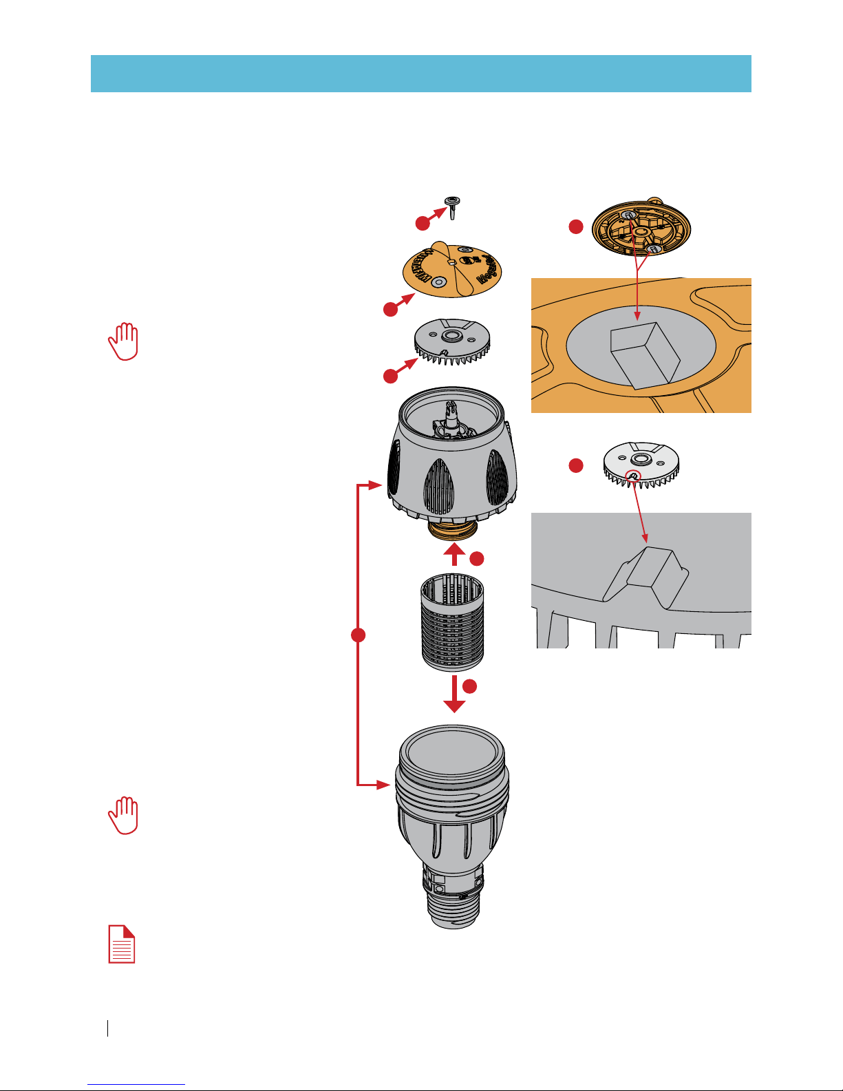
Checking the turbine and the cover
Frequency:
Before the beginning of each growing season
Action:
1.
Open the sprinkler by unscrewing the
upper body of the sprinkler from its base.
2.
Detach the filter by pulling it down.
3.
Remove the pin by pulling it up with your
fingernail or with a small screwdriver.
CAUTION
Be sure not to lose the pin. It is
esential to the operation of the
sprinkler. Aside from indicating
the sprinkler trajectory angle it
also serves to hold the cover
and the turbine in place.
4.
Push the sprinkler's top mechanism
up and hold it.
5.
Remove the colored cover
by pulling it up.
6.
Remove the turbine by pulling it up.
7.
Visually check the 2 black tabs on
the underside of the colored cover
for wear.
8.
Visually check the tab on the
top side of the turbine for wear.
If any of them is worn, replace both
parts - the cover and the turbine.
9.
Put the filter back in place.
10.
Reassemble the sprinkler.
CAUTION
Do not forget to put the pin
back in place. It is esential to
the operation of the sprinkler.
1
2
3
4
5
6
7
8
NOTE
It is recommended to replace the
cover and the turbine every 2000
irrigation hours.
Page 15

MegaNetTM USER MANUAL
15
Cleaning the nozzle
CAUTION
Never operate the sprinkler without the filter.
Failure to comply with this instruction will clog the sprinkler, and may damage it and void the warranty.
If the above instruction is followed, the sprinkler nozzle should never get clogged.
In the event that the sprinkler has been operated without the filter in place, it is possible to clean the nozzle.
Follow the instructions below:
NOTE
The drawings below present the sprinkler's upper body without the pin, the colored cover and the
turbine, to show the actions described. In practice, these 3 parts are connected to the top of the
diverter throughout the dismantling and reassembling process, and do not interfere with it.
NOTE
2 service keys are supplied with each box of MegaNet™ sprinklers. Additional service keys can be
ordered separately (Cat. No. 63620-004500).
1.
Open the sprinkler by unscrewing the upper body of the sprinkler from its base (see page 21, step 1).
2.
Push the sprinkler's top mechanism up and hold it (see page 21, step 4).
MAINTENANCE
Groove
TabTab
Slot
3.
Insert the slotted end of a service key
underneath the diverter holder.
4.
Push the far end of the service key down to the horizontal
position with the groove underneath the key resting on the rim
of the sprinkler's upper body. In this position, the service key
should hold in place.
ATTENTION
There are 2 opposing tabs on the underside
of the diverter holder. Make sure that the
slot of the service key holds one of the tabs.
Page 16

16
MegaNet
TM
USER MANUAL
MAINTENANCE
Diverter
5.
Release the diverter using the other end of the
second service key.
Clean
6.
Clean the nozzle from the top with a water jet or
pressurized air.
7.
To reassemble the sprinkler perform the
steps above in reverse order.
When putting the diverter back in place, turn the
key clockwise until the diverter snaps in place.
A click should be heard.
CAUTION
When reassembling the sprinkler, do not
forget to put the filter in place to avoid
clogging the nozzle in the future.
Hold the first service key in place and turn the
second service key counterclockwise to release the
diverter.
Page 17

MegaNetTM USER MANUAL
17
Parts
MegaNet™ -
½" threaded inlet connector,
head only
Flow
rate*
(l/h)
Nozzle
size
(mm)
Color
code
Catalog number
24D 15D
200 1.8 5 Yel low 63600-001700 63600-004900
250 2.06 Purple 63600-0 01750 63600-004950
350 2.44 Green 63600-001000 63600-005000
450 2.79 Blue 63600-002000 63600-006000
550 3.08 Brown 63600-003000 63600-007000
650 3.37 Orange 63600-004000 63600-008000
750 3.68 Red 63600-004500 63600-009000
* Nominal flow rate at 2.3 bar working pressure.
Packaging data
MegaNet™
Units
p/box
Box size
(cm)
Box weight
(Kg)
Boxes
p/pallet
Total unit s
p/pallet
Pallet weight
(Kg)
Head only 200 18 x 34 x 79 11. 0 20 4000 232
MegaNet™ cover
Flow
rate*
(l/h)
200 250 350 450 550 650 750
Color
code
Yellow Purple Green Blue Brown Orange Red
Catalog
number
63620
-
004850
63620
-
004900
63620
-
005000
63620
-
005100
63620
-
005200
63620
-
005300
63620
-
005400
* Nominal flow rate at 2.3 bar working pressure.
MegaNet™ parts
PARTS AND COMPLEMENTARY PRODUCTS
Part description Catalog number
Turbine (black)
for 24D models
with flow rates 200-350 l/h
63600-002000
Turbine (grey)
for all 15D models
and 24D models
with flow rates 450-750 l/h
63600-006000
Part description Catalog number
Pin for 24D (black) 63600-00175 0
Pin for 15D (grey)
63600-004950
Part description Catalog number
Filter 63620-004400
Page 18

18
MegaNet
TM
USER MANUAL
PARTS AND COMPLEMENTARY PRODUCTS
MegaNet™ accessories
Product
description
Road protector
Catalog
number
63620-007000
Product
description
Ser vice key
Catalog
number
63620-004500
Complementary products
Product
description
In-line pressure regulator,
¾" female - ½" female.
2.5 bar nominal outlet pressure.
Catalog
number
31000-002200
Pressure regulator
Page 19

MegaNetTM USER MANUAL
19
PARTS AND COMPLEMENTARY PRODUCTS
Special model for cement connection (blue base)
Product description
20 mm ISO inlet connector ½" ASTM inlet connector
Flow
rate*
(l/h)
Nozzle
size
(mm)
Color
code
Catalog number Catalog number
24D 15D 24D 15D
200 1.8 5 Yel low
** ** ** **
250 2.06 Purple
** ** ** **
350 2.44 Green
** ** ** **
450 2.79 Blue
**
63600 -010100
**
63600-010500
550 3.08 Brown
**
63600-010200
**
63600-010600
650 3.37 Orange
** ** ** **
750 3.68 Red
** ** ** **
Models for specific uses, head only
Special model with anti-drain valve
Product description
½" threaded inlet connector + AD
Flow
rate*
(l/h)
Nozzle
size
(mm)
Color
code
Catalog number
24D 15D
200 1.8 5 Yel low 63600-001720
**
250 2.06 Purple
** **
350 2.44 Green 63600-001900
**
450 2.79 Blue 63600-002010 63600-005010
550 3.08 Brown 63600-003010 63600-006010
650 3.37 Orange 63600-004010
**
750 3.68 Red 63600-004510
**
* Nominal flow rate at 2.3 bar working pressure.
**Missing catalog numbers available upon request.
Page 20

20
MegaNet
TM
USER MANUAL
Special model for cement connection (blue base)
Can be cemented to the end of a PVC riser tube in solid set installations. Effective for theft prevention.
2 types are available:
• ISO C 20 mm
• ASTM C ½"
Cementing to a ½" (or 20 mm) PVC pipe
NOTE
Read and understand all the instructions before performing this procedure.
1.
Use WELD-ON 717 PVC cement and P68 primer or their equivalents.
2.
Trim the application brush to the desired shape.
3.
Dip the application brush in the P68 primer. Squeeze the brush to remove excess solvent.
4.
Using the brush, clean the inner surface of the socket with the primer.
5.
Using the brush, clean the outer surface of the sprinkler housing with the primer.
6.
Wait 60 seconds for the primer to dry befor applying the cement and then neatly apply the cement to
the outer surface of the sprinkler housing.
7.
Apply the cement to the cylindrical part of
the sprinkler housing below the circular rib.
8.
Insert the sprinkler housing into the socket
in a rotational motion (1/4 turn) to spread the
cement over the entire surface. Make sure
the sprinkler is fully inserted into the socket.
9.
Hold the sprinkler and socket together
for about 30 seconds to make sure they are
firmly connected.
10.
Remove any excess cement with a dry cloth.
11.
Repeat all the steps above when cementing
the socket to the riser tube.
12.
Wait at least 6 hours for the cement to fully
solidify before running water through the
sprinkler.
APPENDIX 1: SPECIAL APPLICATIONS
8 11 12
Page 21

MegaNetTM USER MANUAL
21
Special model with anti-drain valve
For use in slopped fields in order to prevent drainage of the distribution pipe and
possible over-saturation of the soil, unwanted puddles or landslide.
Features and benefits
• Automatic end-of-irrigation shut-off valve.
• Prevents water backflow or drainage of the system into low areas.
• Eliminates the need for system water refill at the beginning of the next irrigation cycle.
• Shut-off pressure: 0.6 bar
Installation
The installation process of this model is similar to that of the regular model
(see pages 10-19).
Screwing and tightening of the sprinkler can be done by hand. The use of a 20 mm
spanner is not necessary.
Adding a PRV (pressure regulating valve)
Install a PRV at the sprinkler inlet when a 100% flow rate and
distribution uniformity is required.
The presented model is suitable for an exit pressure of 2.5 bar.
For other exit pressure values, contact your local Netafim™
representative.
Installation
The installation process of the sprinkler and PRV is similar to that
of installation on solid set riser pipes (see page 12).
Screwing and tightening of the PRV should be done by hand.
ATTENTION
Make sure the PRV is connected to the sprinkler
with the arrow pointing towards the sprinkler (up).
NOTE
The PRV bottom thread is ¾" female. To connect the PRV to
a riser with a thread that is not ¾" male, use an apropriate
adapter/reducer from the vast selection offered by Netafim™
(see page 26 and at XXX).
APPENDIX 1: SPECIAL APPLICATIONS
Arrow
¾" male
thread
Page 22

22
MegaNet
TM
USER MANUAL
Road protector
To avoid wetting the roads around the field, Netafim™ offers a road protector to be used on the sprinklers
at the boundaries of the field.
Installing the road protector
1.
Place the road protector on top of the
sprinkler with its back side facing the
road you want to protect from water.
2.
Push the road protector down onto the
sprinkler head. Clicks should be heard.
3.
Slightly rotate the road protector until
more clicks are heard.
Removing the road protector
1.
Push the 2 ears outwards and up to release the road protector from the sprinkler.
APPENDIX 1: SPECIAL APPLICATIONS
CLICK!
CLICK!
2 3
Page 23

MegaNetTM USER MANUAL
23
WARRANTY
Netafim™ warrants all the components of the MegaNet™ sprinkler to be free of substantial defects in
material and workmanship for a period of 1 (one) year from the date of purchase.
If a defect is discovered during the applicable warranty period, Netafim™ will repair or replace, at its
discretion, the product or the defective part.
This warranty does not extend to repairs or replacements of a MegaNet™ sprinkler or part resulting from
misuse, negligence, alteration, force majeure, lightning, improper installation or improper maintenance,
including any maltreatment of the MegaNet™ sprinkler or any part of the irrigation systems.
If a defect arises in your Netafim™ product during the warranty period, contact your Netafim™ supplier.
Limited warranty
This warranty is subject to the terms and conditions contained in Netafim's official warranty statement in
force at the time of application.
For the full text of Netafim's official warranty statement, go to:
http://www.netafim.com/irrigation-products-technical-materials
Page 24

GROW MORE WITH LESS
WW W.NE TAFIM.COM
 Loading...