

Page 1

TM
User
Guide
MAX T1/E1
VoIP Gateway
Version 1.0
Page 2

THE SPECIFICATIONS AND INFORMATION REGARDING THE PRODUCTS IN THIS MANUAL ARE
SUBJECT TO CHANGE WITHOUT NOTICE. ALL STATEMENTS, INFORMATION, AND
RECOMMENDATIONS IN THIS MANUAL ARE BELIEVED TO BE ACCURATE BUT ARE PRESENTED
WITHOUT WARRANTY OF ANY KIND, EXPRESS OR IMPLIED. USERS MUST TAKE FULL
RESPONSIBILITY FOR THEIR APPLICATION OF ANY PRODUCTS.
THE SOFTWARE LICENSE AND LIMITED WARRANTY FOR THE ACCOMPANYING PRODUCT ARE
SET FORTH IN THE INFORMATION PACKET THAT SHIPPED WITH THE PRODUCT AND ARE
INCORPORATED HEREIN BY THIS REFERENCE. IF YOU ARE UNABLE TO LOCATE THE
SOFTWARE LICENSE OR LIMITED WARRANTY, CONTACT YOUR NET2PHONE REPRESENTATIVE
FOR A COPY.
The following information is for FCC compliance of Class A devices: This equipment has been tested and
found to comply with the limits for a Class A digital device, pursuant to part 15 of the FCC rules. These
limits are designed to provide reasonable protection against harmful interference when the equipment is
operated in a commercial environment. This equipment generates, uses, and can radiate radio-frequency
energy and, if not installed and used in accordance with the instruction manual, may cause harmful
interference to radio communications. Operation of this equipment in a residential area is likely to cause
harmful interference, in which case users will be required to correct the interference at their own expense.
The following information is for FCC compliance of Class B devices: The equipment described in this
manual generates and may radiate radio-frequency energy. If it is not installed in accordance with
Net2Phone's installation instructions, it may cause interference with radio and television reception. This
equipment has been tested and found to comply with the limits for a Class B digital device in accordance
with the specifications in part 15 of the FCC rules. These specifications are designed to provide
reasonable protection against such interference in a residential installation. However, there is no
guarantee that interference will not occur in a particular installation.
Modifying the equipment without Net2Phone's written authorization may result in the equipment no longer
complying with FCC requirements for Class A or Class B digital devices. In that event, your right to use the
equipment may be limited by FCC regulations, and you may be required to correct any interference to
radio or television communications at your own expense.
You can determine whether your equipment is causing interference by turning it off. If the interference
stops, it was probably caused by the Net2Phone equipment or one of its peripheral devices. If the
equipment causes interference to radio or television reception, try to correct the interference by using one
or more of the following measures:
· Turn the television or radio antenna until the interference stops.
· Move the equipment to one side or the other of the television or radio.
· Move the equipment farther away from the television or radio.
· Plug the equipment into an outlet that is on a different circuit from the television or radio. (That is, make
certain the equipment and the television or radio are on circuits controlled by different circuit breakers or
fuses.)
Modifications to this product not authorized by Net2Phone could void the FCC approval and negate your
authority to operate the product.
NOTWITHSTANDING ANY OTHER WARRANTY HEREIN, ALL DOCUMENT FILES AND SOFTWARE
OF THESE SUPPLIERS ARE PROVIDED "AS IS" WITH ALL FAULTS. NET2PHONE AND THE ABOVENAMED SUPPLIERS DISCLAIM ALL WARRANTIES, EXPRESSED OR IMPLIED, INCLUDING,
WITHOUT LIMITATION, THOSE OF MERCHANTABILITY, FITNESS FOR A PARTICULAR PURPOSE
AND NONINFRINGEMENT OR ARISING FROM A COURSE OF DEALING, USAGE, OR TRADE
PRACTICE.
IN NO EVENT SHALL NET2PHONE OR ITS SUPPLIERS BE LIABLE FOR ANY INDIRECT, SPECIAL,
CONSEQUENTIAL, OR INCIDENTAL DAMAGES, INCLUDING, WITHOUT LIMITATION, LOST PROFITS
OR LOSS OR DAMAGE TO DATA ARISING OUT OF THE USE OR INABILITY TO USE THIS MANUAL,
EVEN IF NET2PHONE OR ITS SUPPLIERS HAVE BEEN ADVISED OF THE POSSIBILITY OF SUCH
DAMAGES.
Net2Phone MAX, Net2Phone, the NET2PHONE logo and the Net2Phone logo are registered trademarks
of Net2Phone in the U.S. and certain other countries. All other trademarks mentioned in this document are
the property of their respective owners.
Net2Phone MAX User Guide
Copyright © 2000, Net2Phone
All rights reserved.
Printed in Korea.
Page 3

Contents
1. About This Guide...............................................................................................................................1
2. Setting Up IP Address.......................................................................................................................2
2.1. Connecting Console to Net2Phone MAX......................................................................2
2.2. Setting up the IP address of your Net2Phone MAX with console.............................2
3. Logging Into Net2Phone MAX.........................................................................................................4
4. Remote Access IVR Configuration .................................................................................................7
5. Max-to-Max IVR Configuration........................................................................................................9
6. Network and Voice Configuration..................................................................................................11
7. Account Configuration ....................................................................................................................13
8. Routing Table Configuration...........................................................................................................14
9. PBX Configuration...........................................................................................................................16
10. System Information and Commands....................................................................................19
11. System Software Upgrade.....................................................................................................24
11.1. Download Procedure......................................................................................................25
11.2. Upload Procedure...........................................................................................................26
12. T1/E1 Configuration Guide....................................................................................................30
12.1. Overview of Digital Trunk Interface..............................................................................30
12.2. Timing Clock mode Setup .............................................................................................30
12.3. Digital Trunk Setup.........................................................................................................32
12.4. Configuration Setting......................................................................................................42
i
Page 4

User Guide About This Guide
1. About This Guide
This guide contains instructions for configuring your Net2Phone MAX Internet telephony
gateway system using a web browser. (Internet Explorer 4.0 and up recommended)
This guide also contains instructions for setting up the IP address of your Net2Phone MAX
when DHCP service is not available.
The organization of this guide is as follows:
Section 1. About This Guide
Section 2. Setting Up IP Address
Section 3. Logging Into Net2Phone MAX
Section 4. Remote Access IVR Configuration
Section 5. Max-to-Max IVR Configuration
Section 6. Network and Voice Configuration
Section 7. Account Configuration
Section 8. Routing Table Configuration
Section 9. PBX Configuration
Section 10. System Information and Commands
Section 11. System Software Upgrade
Section 12. T1/E1 Configuration Guide & Example
1
Page 5

User Guide Setting Up IP Address
2. Setting Up IP Address
If your network has a DHCP(Dynamic Host Configuration Protocol) server, then there is no need
for manual IP address setting. The Net2Phone MAX system automatically configures IP related
parameter settings itself using the DHCP protocol.
The IP related parameter settings are displayed on console when system boots up. For
connecting console to Net2Phone MAX, refer to section 2.1.
If your network does not have a DHCP server, then you can manually configure IP address
settings through the console port. (Refer to section 2.2)
2.1. Connecting Console to Net2Phone MAX
① Prepare a serial communication cable. (D-sub 9-pin, male-to-female, straight-through
connection)
② Connect the cable from a computer to the Net2Phone MAX.
③ Start HyperTerminal (in windows95/98/NT)or equivalent terminal emulator application
program.
④ Set serial communication parameters as following table
Baud rate 19200
Parity None
Character size 8
Stop Bit 1
Flow Control None
⑤ Execute disconnect command and then execute connect command again.
⑥ Power on the Net2Phone MAX, then wait while the booting messages of Net2Phone MAX
are displayed.
⑦ If login prompt is displayed, login by using one of the following user ID’s.
user ID Password [factory default]
root n2p
manager n2p
sysadm n2p
⑧ Net2Phone MAX supports only 3 management users. You can change each user’s
password, but you cannot add or delete new user for management.
2.2. Setting up the IP address of your Net2Phone MAX with console
This section describes changing the IP related parameters for Net2Phone MAX.
2
Page 6

User Guide Setting Up IP Address
IP address related parameters used in Net2Phone MAX are IP address of Net2Phone MAX,
subnet mask of Net2Phone MAX, and IP address of default gateway. Prepare these values
before starting configuration.
① Make a console connection from your computer to Net2Phone MAX (refer to section 2.1)
② After login to Net2Phone MAX, change directory to “/config/ip” (just type “/config/ip” at
prompt)
③ Change IP address, subnet mask, and default gateway settings using “change” command.
(type “change”, then interactive menu will appear)
④ Reset Net2Phone MAX to reflect changes to the Net2Phone MAX. This is done by issuing
“/system/reset” command or just power-off and after 10 seconds later, power-on.
⑤ Using “ping” command from another computer, confirm the correct IP related parameters
are configured to Net2Phone MAX.
3
Page 7
User Guide Logging Into Net2Phone MAX
3. Logging Into Net2Phone MAX
After obtaining the IP address of your Net2Phone MAX system, you can use a web browser to
configure the Net2Phone MAX. First, you must log into the Net2Phone MAX by following steps
below.
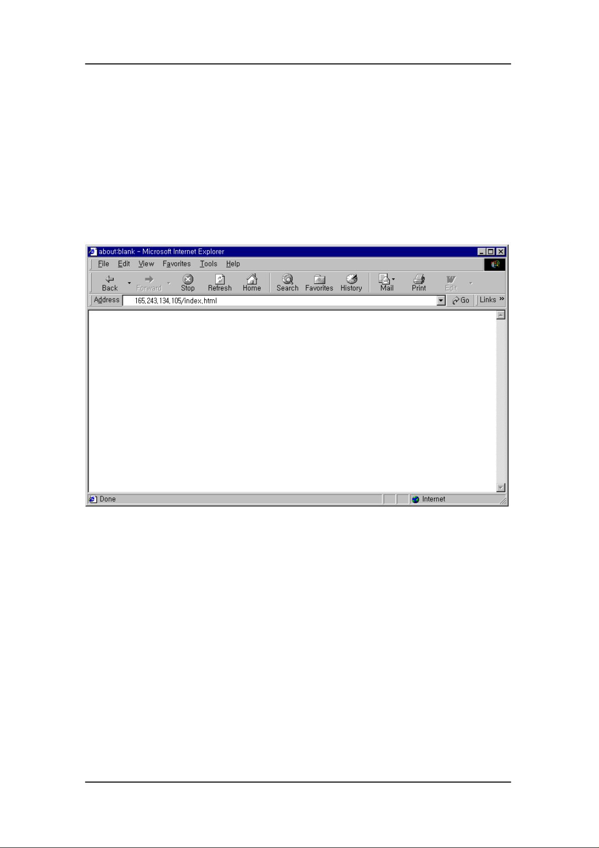
Open a new browser window and enter the IP address in the http address box.
4
Page 8
User Guide Logging Into Net2Phone MAX
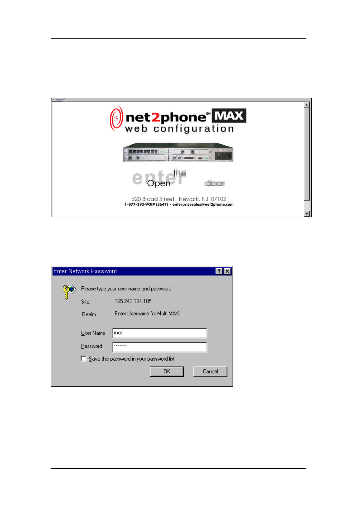
When the intro page is displayed, click the “Open the door” area.
When the network password dialog box appears, enter username and password.
{The default username is root, and the default password is n2p}
5
Page 9
User Guide Logging Into Net2Phone MAX
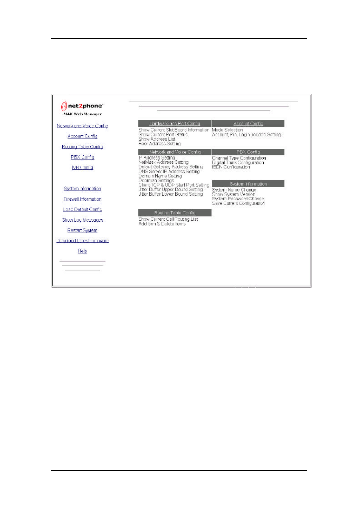
A site map will be displayed. You are now logged in.
6
Page 10
User Guide Remote Access IVR Configuration
4. Remote Access IVR Configuration
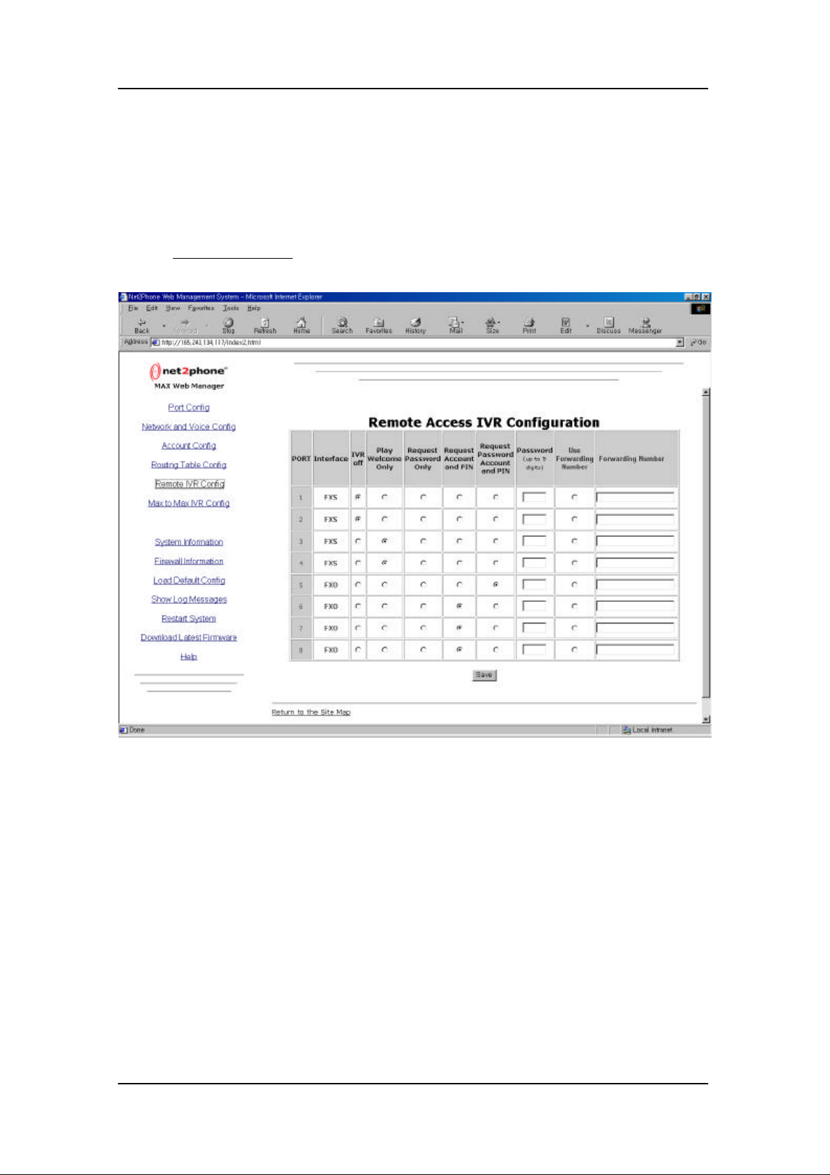
Remote access IVR (Interactive Voice Response) configuration table can be accessed by
clicking “Remote IVR Config” link.
This page shows remote access IVR configurations of the Net2Phone MAX system.
The remote access IVR Configuration table displays current IVR settings for remote dial-in
connection.
User can change these settings for controlling unauthorized access to Net2Phone MAX system.
There are 6 access modes which are :
A. IVR Off : When IVR Off is selected for a port, callers to the port get an immediate
VoIP dial tone and can make VoIP calls without restriction.
7
Page 11

User Guide Remote Access IVR Configuration
B. Play Welcome Only : When this option is selected, callers to the port hear a welcome
message, “Welcome to Net2Phone. Please enter the number you wish to call.” Callers
can then make VoIP calls without restriction.
C. Request Password Only : This option prevents unauthorized access to the T1/E1 on
which it is set. Callers are asked to enter a password through the telephone keypad
before access to VoIP calling is permitted. Callers can then make VoIP calls without
restriction. To configure this option, you must create a password (in the port’s
Password column) which may consist of up to 5 (numeric only) characters.
D. Request Account and PIN : This feature requires the caller to enter a Net2Phone
account number and PIN before VoIP calling is enabled. If the caller then incurs
charges while using the Net2Phone MAX, they will accrue to the caller’s account.
E. Request Password Account and PIN : This option combines the two functions
described above.
F. Use Forwarding Number : Select this IVR option for a port if you wish to have
incoming calls to that port forwarded to a specified number automatically, without
notice to the caller. Any PSTN telephone number, or a Net2Phone account number
preceded by *72, may be entered in the Forwarding Number column. If a PSTN
number is entered, it must include any required preliminary digits, such as a 1 for longdistance calling.
8
Page 12
User Guide Max-to-Max IVR Configuration
5. Max-to-Max IVR Configuration
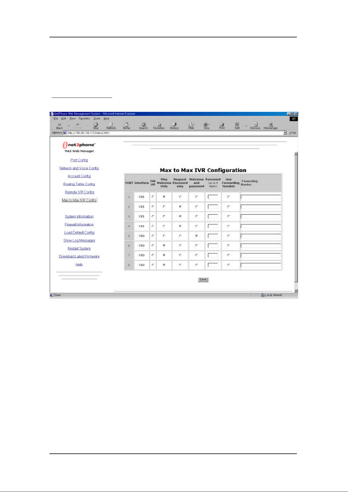
Max-to-Max IVR (Interactive Voice Response) configuration table can be accessed by clicking
“Max-to-Max IVR Config” link.
This figure shows the Max-to-Max IVR Configuration table.
Max-to-Max IVR Configuration table displays current IVR settings for Max-to-Max connection.
User can change these settings for controlling unauthorized access to Net2Phone MAX system.
There are 5 access modes which are :
A. IVR Off : When IVR Off is selected for a port, callers to the port get an immediate
VoIP dial tone and can make VoIP calls without restriction.
B. Play Welcome Only : When this option is selected, callers to the port hear a welcome
message, “Welcome to Net2Phone. Please enter the number you wish to call.” Callers
can then make VoIP calls without restriction.
9
Page 13

User Guide Max-to-Max IVR Configuration
C. Request Password Only : This option prevents unauthorized access to the T1/E1 on
which it is set. Callers are asked to enter a password through the telephone keypad
before access to VoIP calling is permitted. Callers can then make VoIP calls without
restriction. To configure this option, you must create a password (in the port’s
Password column) which may consist of up to 5 (numeric only) characters.
D. Welcome and Password : This option combines the two functions described above.
E. Use Forwarding Number : Select this IVR option for a port if you wish to have
incoming calls to that port forwarded to a specified number automatically, without
notice to the caller. Any PSTN telephone number, or a Net2Phone account number
preceded by *72, may be entered in the Forwarding Number column. If a PSTN
number is entered, it must include any required preliminary digits, such as a 1 for longdistance calling.
10
Page 14
User Guide Network and Voice Configuration
6. Network and Voice Configuration
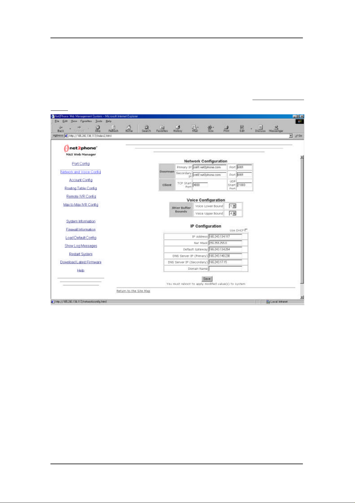
The network and voice configuration page can be accessed by clicking “Network and Voice
Config” link.
This page shows network and voice configurations of the Net2Phone MAX system.
Network configuration figure displays the doorman IP addresses/ports and TCP/UDP start ports.
User can change the IP addresses and port numbers in these boxes.
If your network uses firewall system, then you must make following request to the network
administrator.
{The network administrator must open up at least 3 UDP port and 2 TCP port.}
The following ports must be opened through the firewall:
UDPPORT=6801
UDPPORT=21000,21001
11
Page 15

User Guide Network and Voice Configuration
TDPPORT=21000,21001
The ports must be allowed to make an external connection and a connection back in.
The network administrator must make sure that UDP port 6801 is open. The other UDPPORT &
TCPPORT can be anything in the range from 21000.
Once these port numbers are decided, the end user (Net2Phone MAX user) must set up the
TCP start port and UDP start port parameters in the Network configuration table as specified by
the network administrator.
If there are more than one user, then the network administrator must open up extra 2
UDPPORT & 2 TCPPORT per additional user in consecutive order.
If the customer uses a proxy server, then there is no solution. The Net2Phone Firewall
Information web page states that Net2Phone cannot work through a proxy server under any
circumstance.
Voice configuration figure displays the jitter buffer bounds, which are used for controlling QoS.
User can change the lower/upper bounds where large lower/upper bound means less packet
loss and small lower/upper bound means more packet loss. However, larger lower/upper bound
increases packet delay.
IP configuration figure displays IP related addresses/parameters. User can change IP address
of Net2Phone MAX, netmask, default gateway address, DNS server addresses, and domain
name. User can also enable/disable DHCP client. User must fill in the default gateway and DNS
server address boxes with the number 0.0.0.0 if not used. If these boxes are left blank, then
configuration settings are not saved.
User must click the Save button to save the modified settings, and must reboot to apply the new
settings.
12
Page 16
User Guide Account Configuration
7. Account Configuration
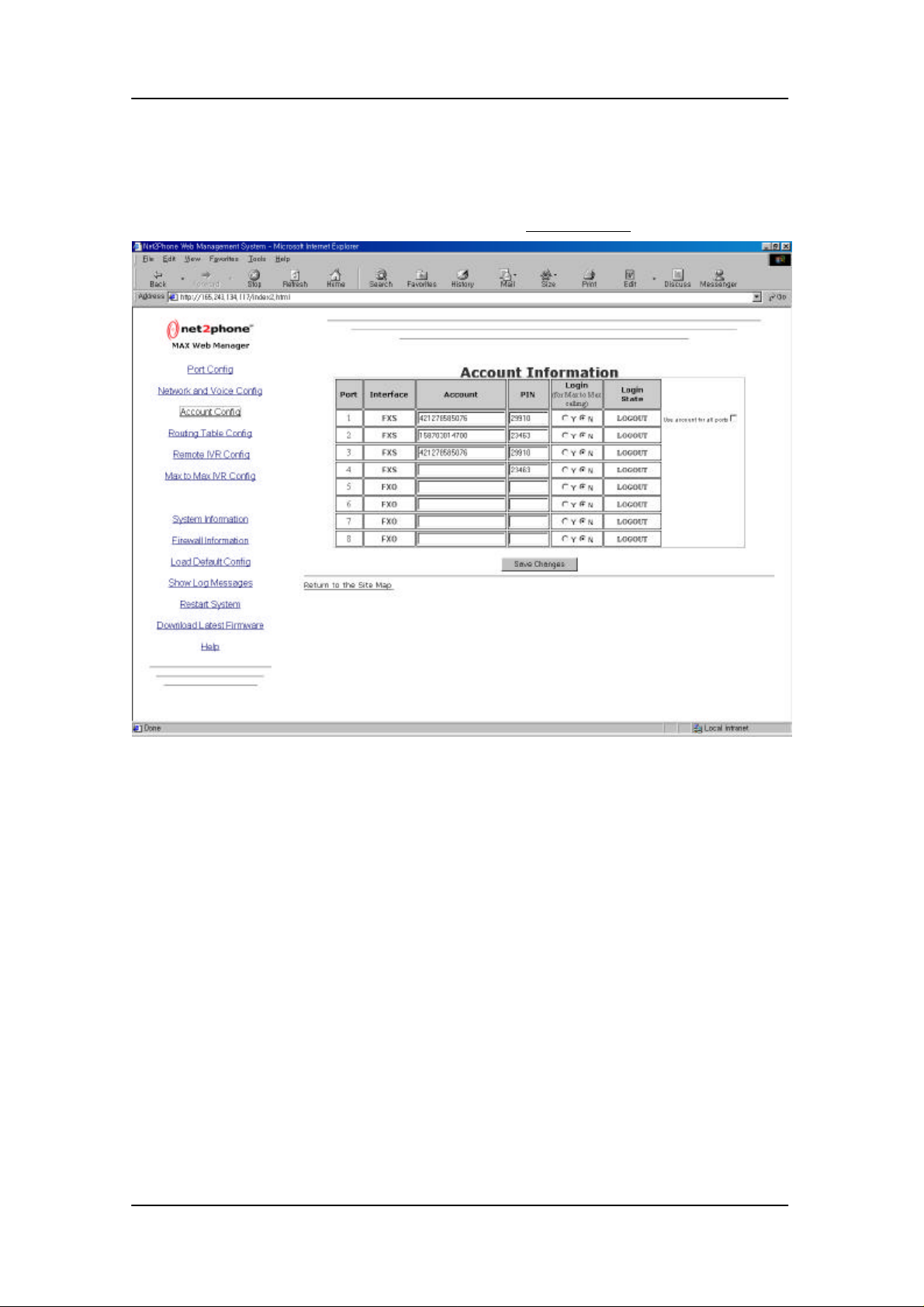
Account configuration page can be accessed by clicking “Account Config” link.
This page shows account configurations of the Net2Phone MAX system.
Account information figure displays the Net2Phone account number, PIN, and the need for login.
If the user of the port want to receive incoming call, then the user must click the “Yes” radio
button.
If the user of the port don’t want to receive incoming call, then the user must click the “No” radio
button.
If the user wants to use the same account number and PIN for all ports with the same login
selection, then the user must check the box named “Use account for all ports”. Then port
number 2 to 8 will use the account number and PIN of port number 1.
User must click the Save button to save the modified settings
13
Page 17
User Guide Routing Table Configuration
8. Routing Table Configuration
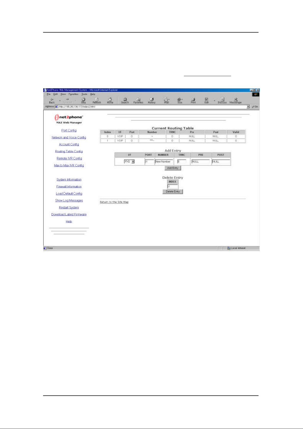
Routing table configuration page can be accessed by clicking “Routing Table Config” link.
This page shows the routing table configurations of the Net2Phone MAX system.
Current routing table figure displays the entry index, the interface type (I/F), the logical port
number (PORT), the phone number to be routed (NUMBER), the truncation length (TRNC), the
prefix number (PRE), postfix number (POST), and the validity of table entry.
For normal use, there is no need for modifying the routing table. However, if you want to support
the in-office calling function, then you must add a new entry for routing calls to other telephones
connected to the Net2Phone MAX system. Also, if you want to have your own numbering plan,
then you can add various entries. To add entries, you fill out the input boxes in the Add Entry
figure, and click the Add Entry button.
To add a new entry, first select the interface type of the port that you want the calls to be routed.
14
Page 18

User Guide Routing Table Configuration
Interfaces type Description
FXS interface for analog telephone
FXO interface for analog PBX port
VOIP interface for IP network
Next, type in the logical port number of the port. This number can be viewed at the hardware
and port configuration page.
The third step is to specifying the call numbers that are to be directed to the port. You can use
following characters.
0,1,2,3,4,5,6,7,8,9,* used for ordinary digits which user can input from telephone
? Represents any one of ordinary digits.
~ Represents any length of any one of ordinary digits.
(Note : ‘#’ characters are used for end-digit indicator, so # character does not appear in number
field of call routing table)
<Example 1>
‘1???’ represents the number which starts with digit 1 followed by any 3 digits.
<Example 2>
‘011~’ represents the number which starts from 011 followed by any length of any digits.
The rest of the input boxes representing the truncation length (TRNC), the prefix number (PRE),
postfix number (POST) are for reserved use and don’t need to be modified.
To delete any unwanted entry, simply type in the entry index number in the Delete Entry box,
and click the Delete Entry button.
However, the VOIP entries with the number field ~ and ***~ can not be deleted, since these 2
entries are necessary for correct operation of the Net2Phone MAX system.
15
Page 19
User Guide Routing Table Configuration
9. PBX Configuration
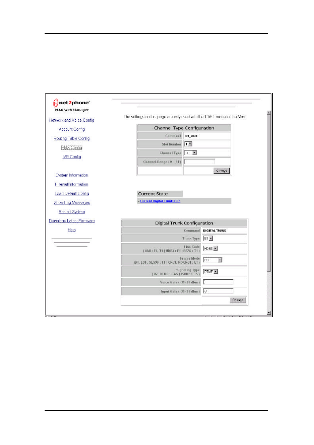
PBX configuration page can be accessed by clicking “PBX Config” link.
This page shows the PBX configurations of the Net2Phone MAX T1/E1 system.
Channel type configuration table enables the user to change the attribute of each channel which
is one of 3 types : incoming(ic)/outgoing(og)/bothway(bw).
User must select the slot number (1~3), channel type (ic/og/bw), and the range of channel
numbers (0~31).
16
Page 20

User Guide Routing Table Configuration
The channel range is limited by the trunk type and the signaling type. If T1 trunk is used, then
the range is reduced to 0~23. And if ISDN PRI signaling with T1 trunk is used, then the range is
reduced to 0~22.
{ * For the E1 trunk, channel 0 and 16 is reserved for sync & signaling channel. So attribute
change is not possible.}
Current state table shows the current attributes of available channels.
Digital trunk configuration table displays the trunk type, line coding method, frame format,
signaling method, voice gain, and input gain. Following table shows possible input parameters.
{Since voice gain and input gain parameter controls are only used when signaling or echo
problem is encountered, it is recommended that average user does not modify these values.}
Digital Trunk Configuration
Trunk Type E1 ,T1
Line Code * AMI, HDB3, B8ZS
Frame Mode ** D4, ESF, SLS96, CRC4, NOCRC4
Signaling Type *** R2, DTMF, ISDN
Voice Gain -31~31 dbm
Input Gain -31~31 dbm
* AMI is used by both E1, T1 while HDB3 is used only by E1 and B8ZS is used only by T1
** D4, ESF, SLS96 are used only by T1, and| CRC4, NOCRC4 are used only by E1
*** R2 signaling is not used in North America.
17
Page 21
User Guide Routing Table Configuration
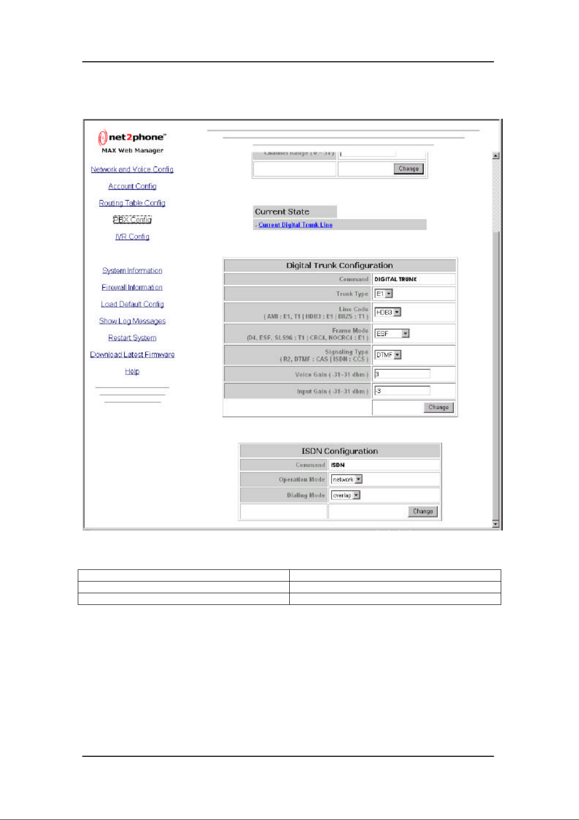
ISDN configuration table displays the operation mode and the dialing mode for ISDN service.
ISDN Configuration
Operation mode User, Network
Dialing mode Overlap, enbloc
User mode is used when the ISDN PRI board is in network mode.
Network mode is used when the ISDN PRI board is in user mode.
Overlap mode is used when user wants to send phone number digits separately one by one.
Enbloc mode is used when user wants to send phone number digits as one continuous frame.
18
Page 22
User Guide System Information and Commands
10. System Information and Commands
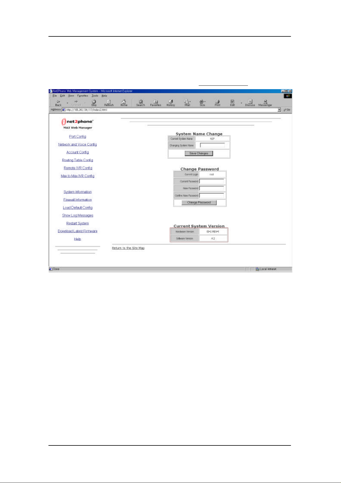
The system information page can be accessed by clicking “System Information” link.
This page shows the system name, the current user name, and the current system version of
the Net2Phone MAX system. User can change the system name and the user password.
19
Page 23
User Guide System Information and Commands
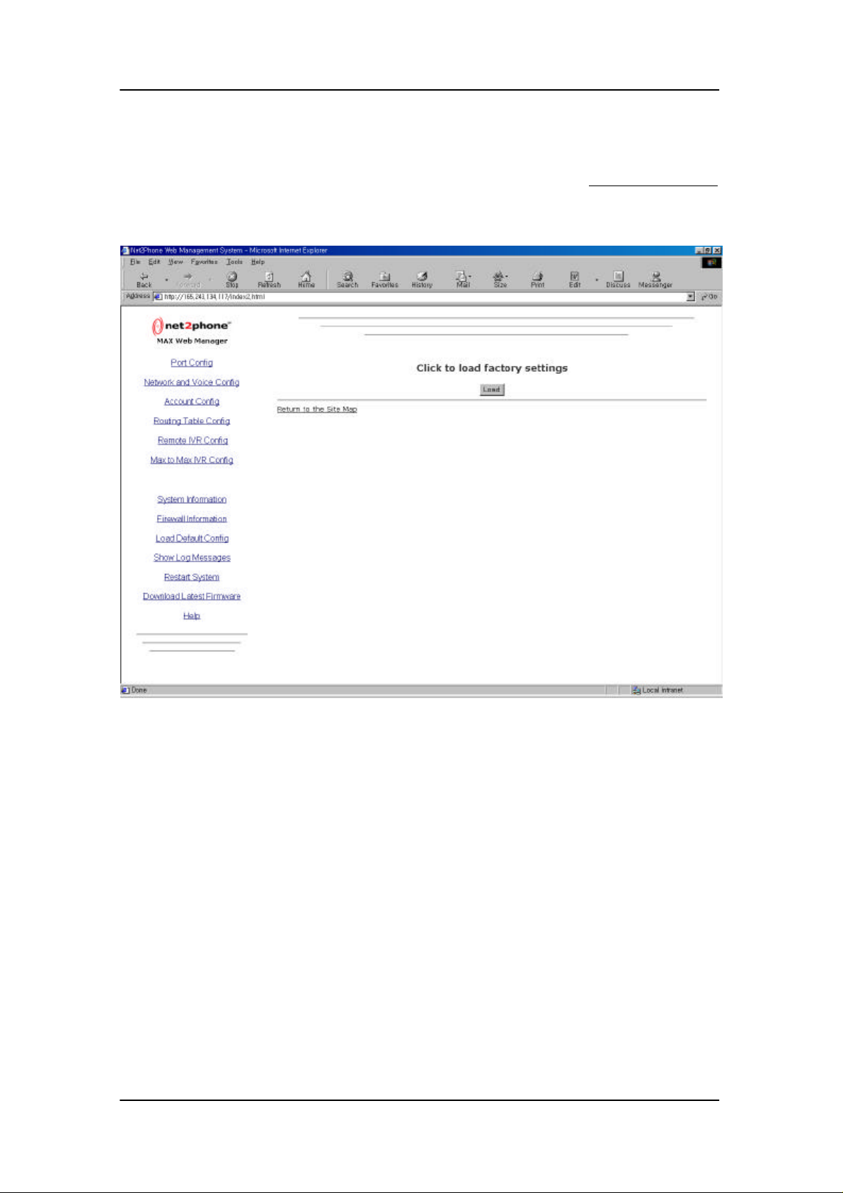
The page for default configuration loading can be accessed by clicking “Load Default Config”
link.
You can load the default configurations by clicking the Load button. (Refer to Net2Phone MAX
User Guide for system default settings)
20
Page 24
User Guide System Information and Commands
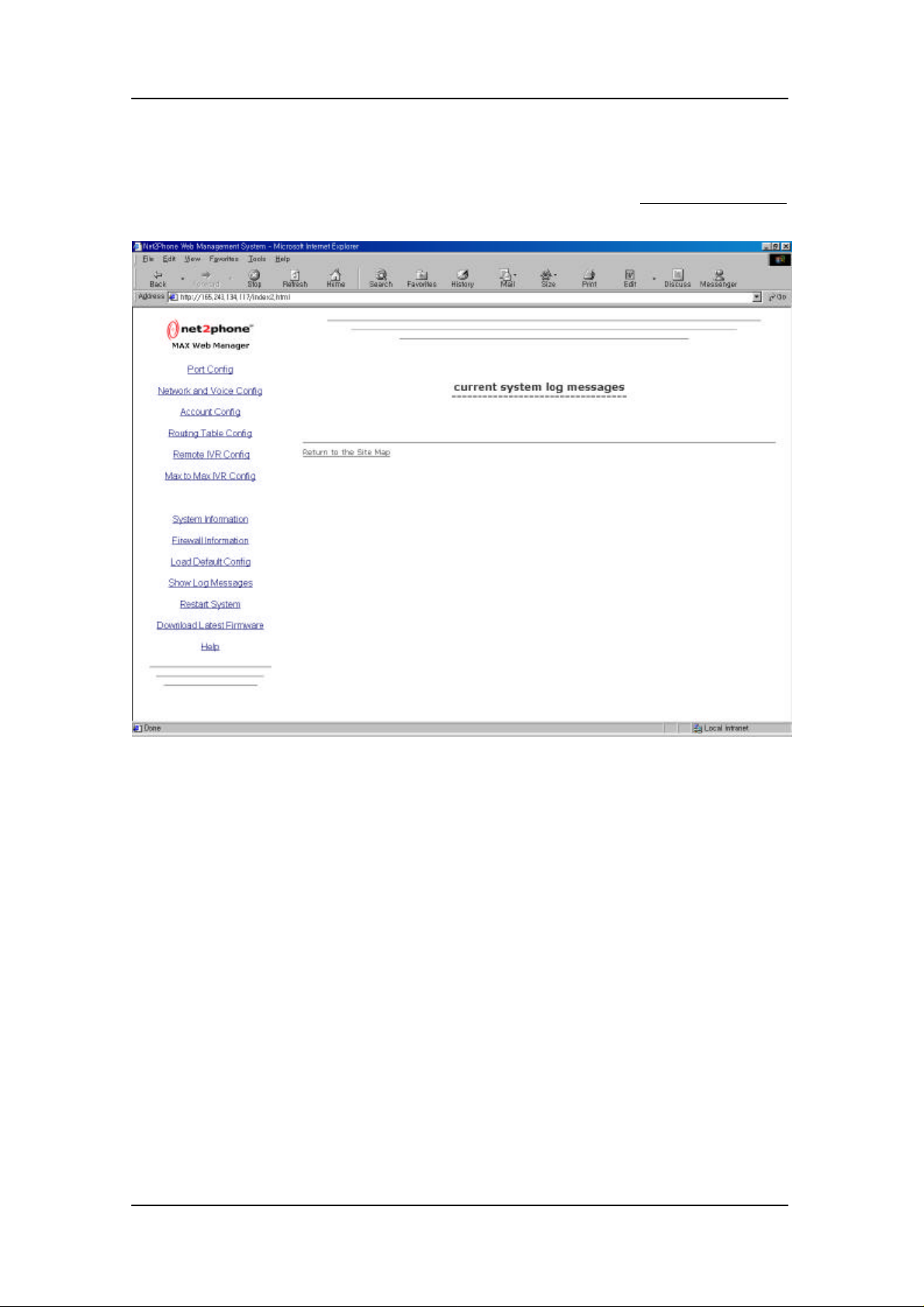
The page for system log message display can be accessed by clicking “Show Log Messages ”
link.
21
Page 25
User Guide System Information and Commands
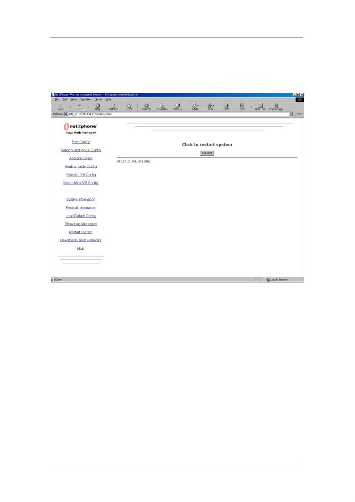
The page for system reboot command can be accessed by clicking “Restart System” link.
You can reboot the system by clicking the Restart button.
22
Page 26
User Guide System Information and Commands
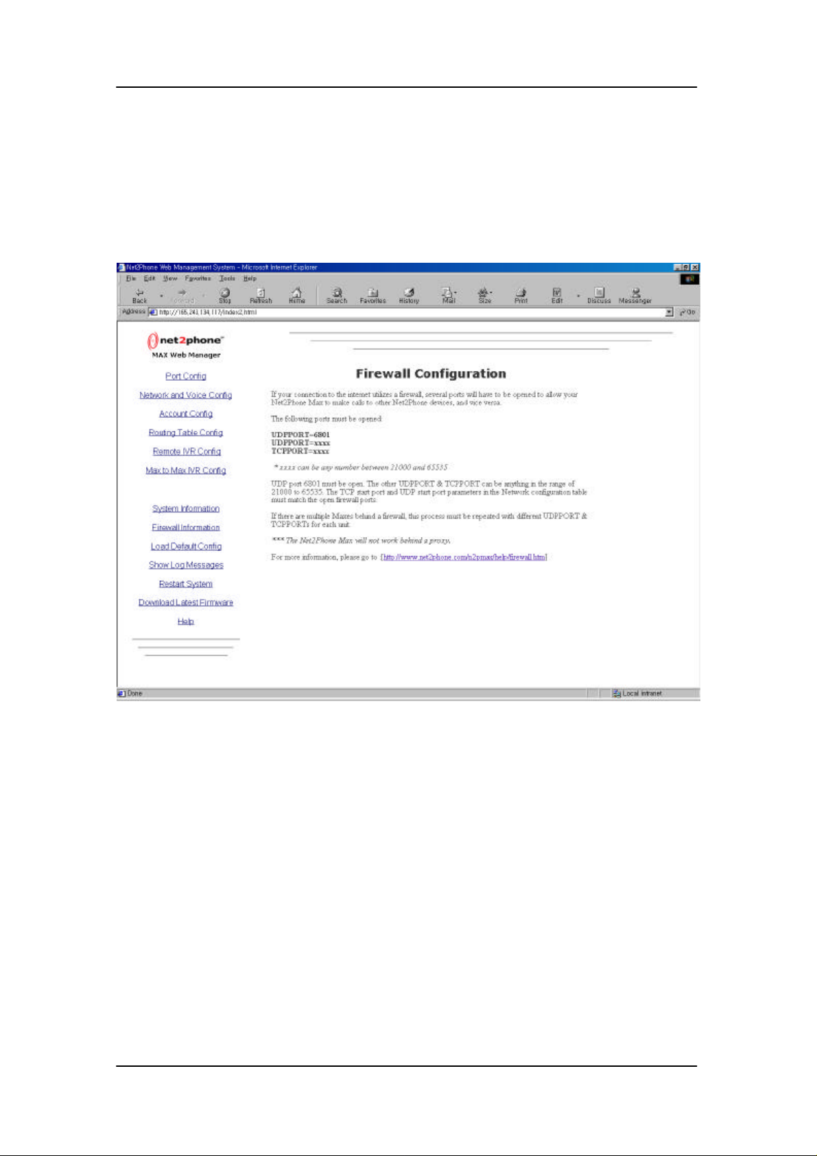
The “Firewall Information” link opens a web page describing procedures for enabling net2phone
access through the firewall system.
23
Page 27
User Guide System Software Upgrade
11. System Software Upgrade
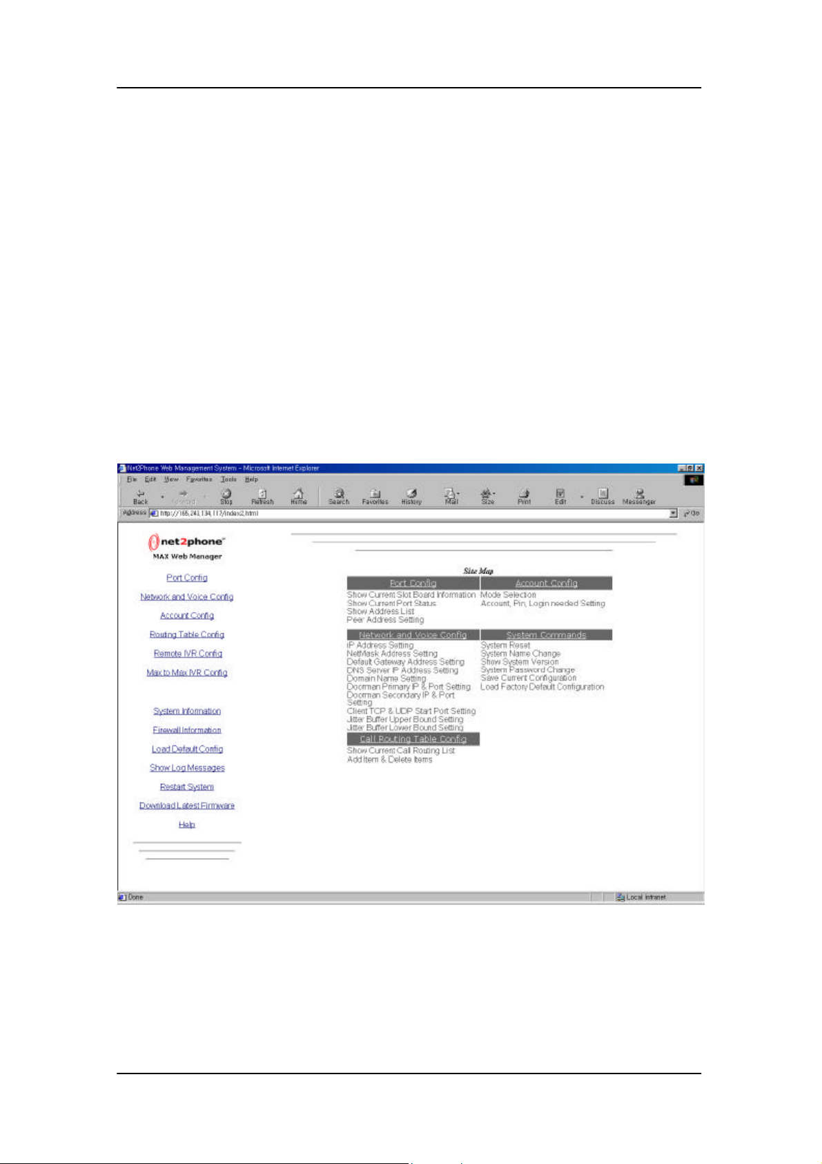
The software upgrade procedure for Net2Phone MAX is divided into 2 parts. The first part is to
download necessary files for upgrade from Net2Phone FTP server. The second part is to
upload the new software to the Net2Phone MAX system. Before beginning the upgrade,
following information must be prepared.
ü Username
ü Password
ü IP address of Net2Phone MAX
To upgrade the system software of Net2Phone MAX, you also need create a new directory
named “C:\net2phone\upgrade” in your PC.
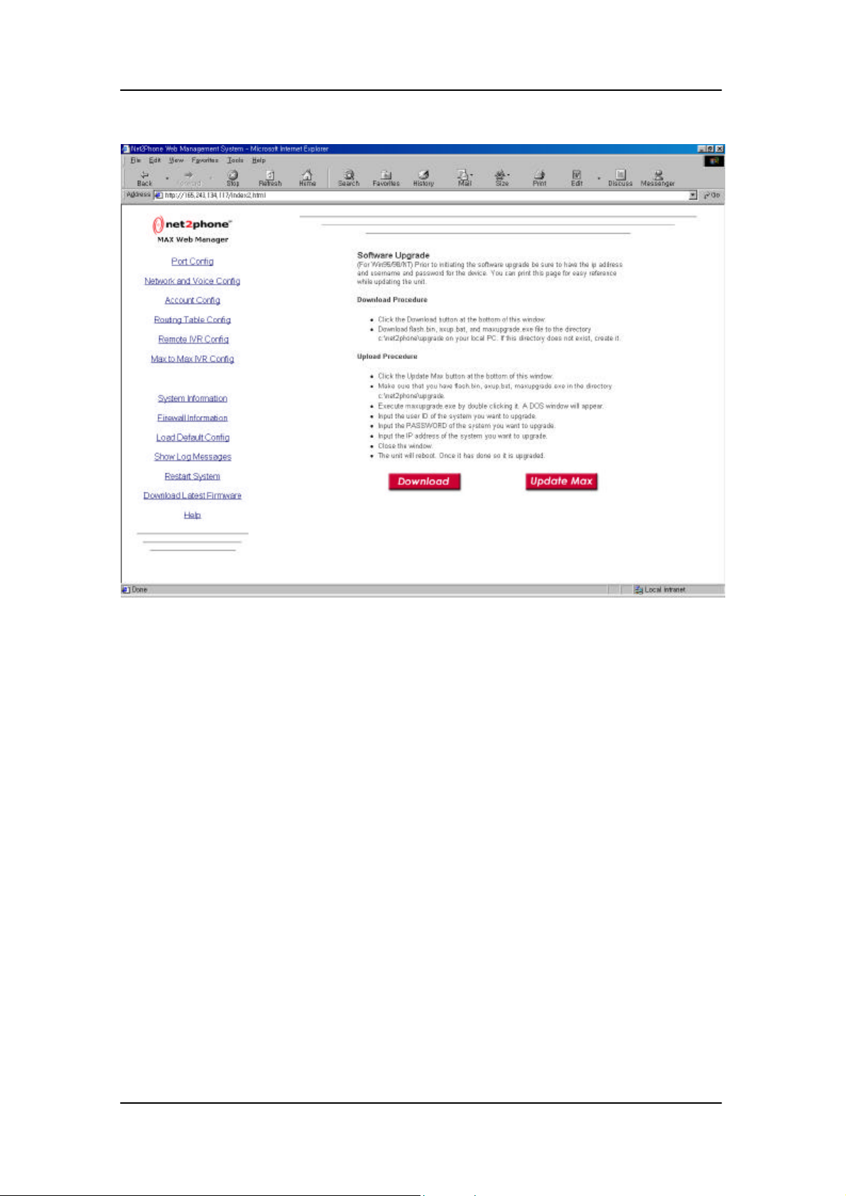
The upgrade procedure is started by clicking the “Download Latest Firmware” link.
After clicking the “check for software upgrade” image, the software download/upload page will
appear which explains the upgrade procedure.
24
Page 28
User Guide System Software Upgrade
11.1. Download Procedure
Download procedure obtains the necessary files for upgrading Net2Phone MAX from
Net2Phone FTP server.
Make sure that you have a directory named “C:\net2phone\upgrade” in your PC.
Click the download button at the bottom of this window. A browser window will pop up which is
automatically connected to the FTP server with anonymous login.
25
Page 29
User Guide System Software Upgrade
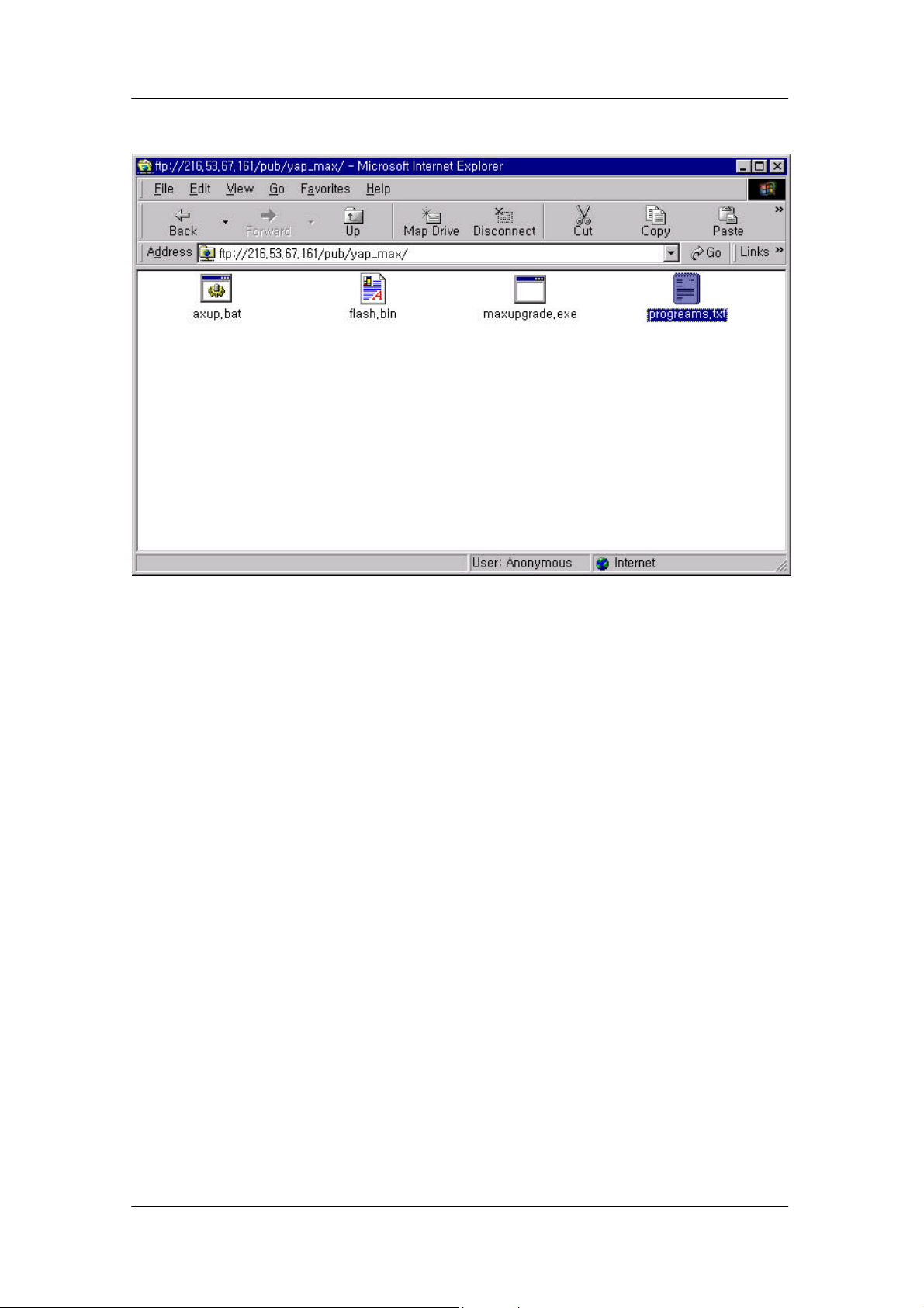
Check the readme file for software update information. If a new software version is currently in
the FTP server, then download flash.bin, vocfile.bin, axup.bat, and maxupgrade.exe file to
C:/net2phone/upgrade directory. Make sure that the downloaded software version is newer than
the installed software version. You can go to “System Information” page for current software
version number.
11.2. Upload Procedure
Upload procedure installs the new software to the Net2Phone MAX system.
Make sure that you have flash.bin, vocfile.bin, axup.bat, and maxupgrade.exe in the directory
C:/net2phone/upgrade.
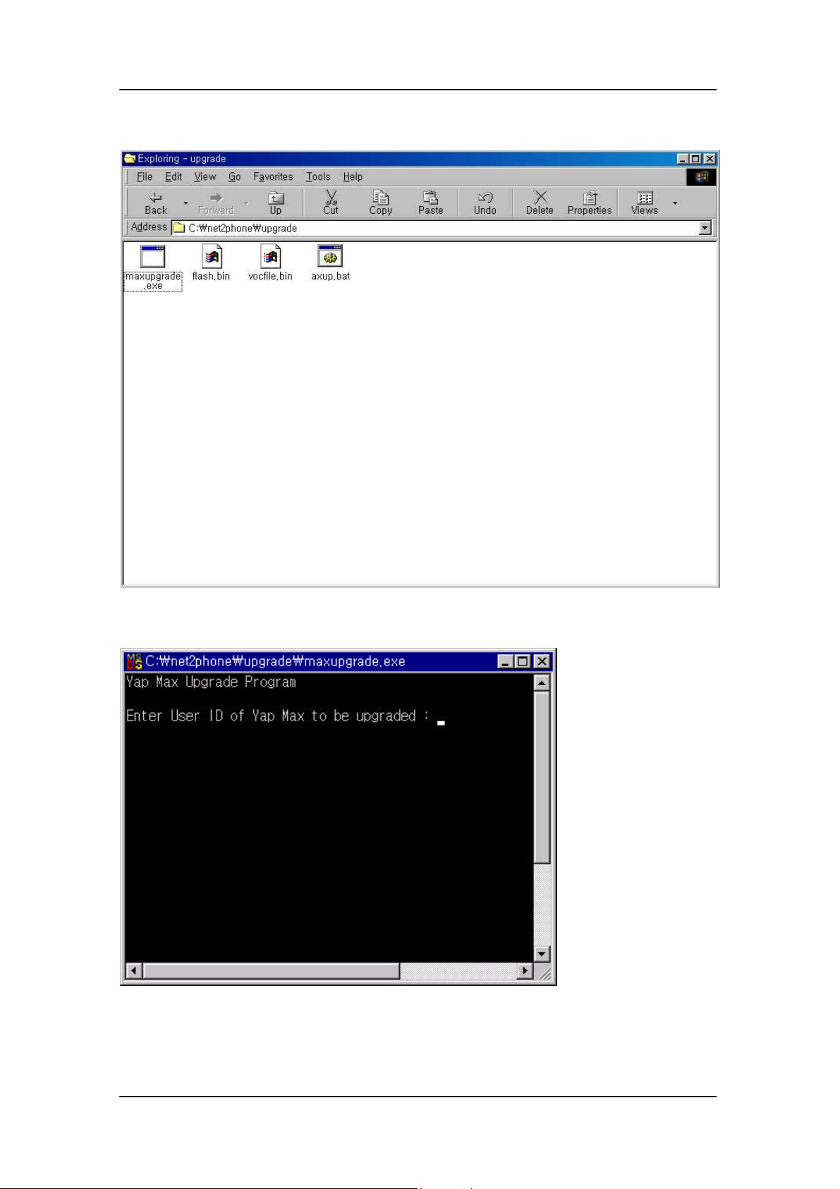
Click the upload button at the bottom of this window. An explorer window will pop up with the
address C:/net2phone/upgrade. There will be 4 files present, which are flash.bin, vocfile.bin,
axup.bat, and maxupgrade.exe
26
Page 30
User Guide System Software Upgrade
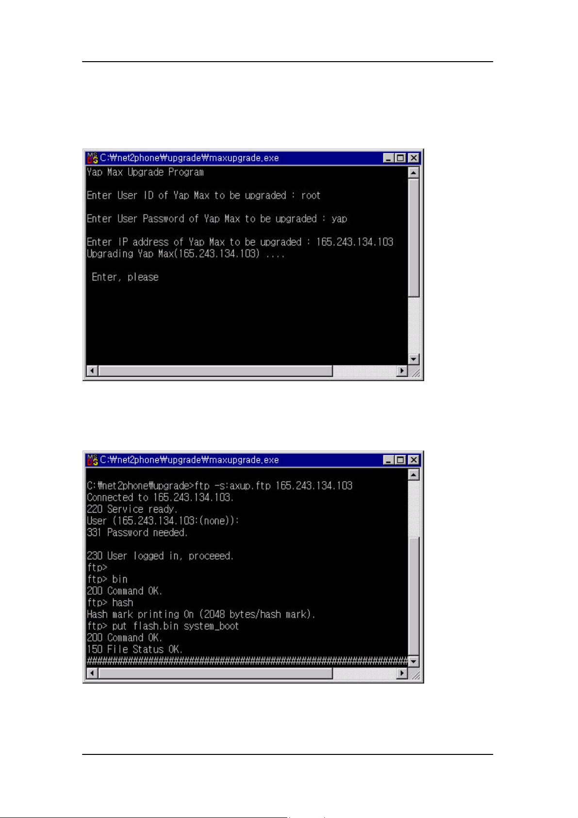
Execute maxupgrade.exe by double clicking it. A DOS window will appear.
27
Page 31
User Guide System Software Upgrade
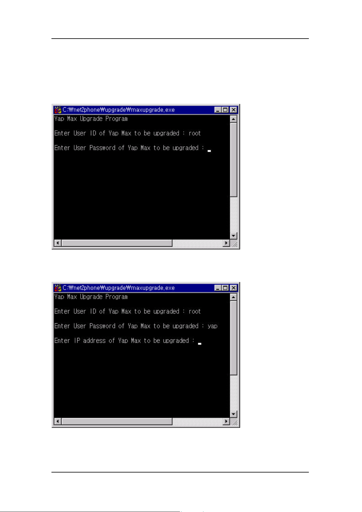
Input your ID of the system you want to upgrade and press enter.
Input your PASSWORD of the system you want to upgrade.
28
Page 32
User Guide System Software Upgrade
Input IP address of the system you want to upgrade.
Enter return key two times. An FTP application starts to upload the new software to Net2Phone
MAX.
After upload is completed, a “press any key to continue” message will appear. Close the window
by pressing enter key. The Net2Phone MAX system reboots itself after the software upgrade.
29
Page 33

User Guide T1/E1 configuration guide
12. T1/E1 Configuration Guide
12.1. Overview of Digital Trunk Interface
Digital trunk interface is used for transferring a large volume of call traffic between exchange
equipments (PBX or KTS) or between Exchange equipment and peripherals.
Digital trunk interface has signaling function, which exchanges information needed for traffic
path setup, release and monitoring, and supervisory control function, which performs status
management function and error diagnosis for trunk line.
Digital trunk interface is generally classified into E1 interface and T1 interface depending on
transmitting speed and has various types of interface depending on timing, frame mode, line
encoding, signaling, etc.
12.2. Timing Clock mode Setup
To maintain error-free communication state between two exchange equipments connected
by digital trunk, timing clock signal must be synchronized for exact clock extraction and data
tranceiving.
One of them generates timing clock signal, sends it to remote side, this clock generating
system is called clock source or clock master, and the remote side receiving timing clock
from clock master makes itself synchronization with clock master system using phase
locked loop circuit, this system is called clock slave.
Yap Max system has a chip, this chip contains phase locked loop circuit, so that this system
can be used as clock master or clock slave.
Commands for timing clock mode setup of MAX system are executed in the directory of
‘MAX:/CONFIG/COMMON’.
MAX:/CONFIG/COMMON>change clkp <value>
MAX:/CONFIG/COMMON>change clks <value>
‘Clkp’ is the parameter to set primary system clock source and has option values like
‘freerun’ and ‘dvu’.
The former option value ‘freerun’ means clock master and the latter option value ‘dvu’
means clock slave.
‘Clks’ is the parameter to set secondary system clock source but this parameter is used only
when several DVU boards are inserted into a system.
‘Clks’ parameter can be set with the same value as ‘clkp’.
30
Page 34
User Guide T1/E1 configuration guide
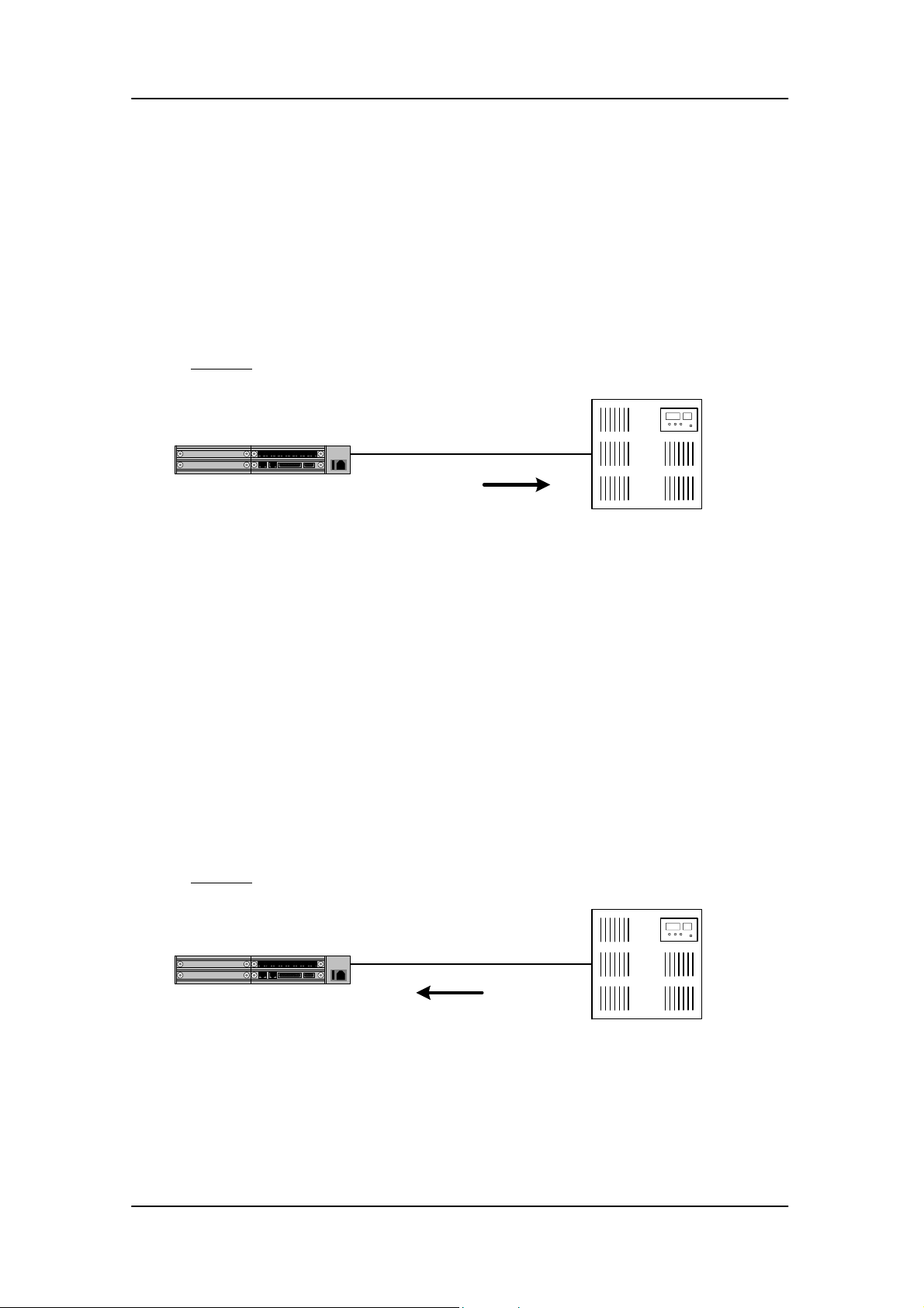
12.2.1. When MAX is set as clock master.
In this case, timing clock signal that MAX system generates is used for
telecommunication over digital trunk interface between AX-200 and exchange
equipment (PBX in the figure 1)
Figure 1. Clock Master Diagram
T1/E1
clock
MAX
PBX
The command settings for clock master are as follows:
MAX:/CONFIG/COMMON>change clkp freerun
MAX:/CONFIG/COMMON>change clks freerun
12.2.2. When MAX is set as clock slave.
In this case, MAX system receives timing clock signal that exchange equipment (PBX
in the figure 2) generates and have to make own system clock synchronization to this
timing clock signal.
Figure 2. Clock Slave Diagram
MAX
T1/E1
clock
PBX
The command setting for clock slave are as follows:
MAX:/CONFIG/COMMON>change clkp dvu
MAX:/CONFIG/COMMON>change clks dvu
31
Page 35

User Guide T1/E1 configuration guide
12.3. Digital Trunk Setup
Digital trunk is classified into E1 (2.048Mhz) and T1 (1.544Mhz) depending on transmission
speed.
Command for digital trunk setup is executed in the directory of ‘MAX:/CONFIG/DTRUNK>’.
MAX:/CONFIG/DTRUNK>change cfg type <value>
The option value can be defined as ‘T1’ or ‘E1’.
12.3.1. Line Coding
Line coding means transformation of original digital bit stream to optimized bit pattern
for easy clock extraction and error detection.
AMI (Alternate mark inversion) and B8ZS (Binary 8-zero substitution) line codings are
used in the T1 trunk and HDB3 (High-Density Bipolar-3 zeros) and AMI line codings are
used in the E1 trunk.
The line coding of MAX must be identical to that of counterpart exchange
equipments.(PBX)
Command to set line coding is executed in the directory of ‘MAX:/CONFIG/DTRUNK>’.
MAX:/CONFIG/DTRUNK>change cfg lcode <value>
The option value can be defined as ‘AMI’, ‘HDB3’, or ‘B8ZS’.
12.3.2. Frame Type
Data transmitted and received through digital trunk forms a bundle of bit, is called as
frame.
Frame types like SF (Super Frame), ESF (Extended Super Frame) and D3/D4 are used
in the T1 trunk and CRC4 and non-CRC4 frames are used in the E1 trunk.
The frame type of MAX must be identical to that of counterpart exchange
equipments.(PBX)
Command to set frame type is executed in the directory ‘MAX:/CONFIG/DTRUNK>’.
MAX:/CONFIG/DTRUNK>change cfg frame <value>
The option value can be defined as ‘D4’, ‘ESF’, ‘SLS96’, ‘CRC4’, or ‘NOCRC4’.
32
Page 36

User Guide T1/E1 configuration guide
12.3.3. Signaling Setup
Signaling is a protocol to exchange information needed for line monitoring, call setup or
release between exchange equipments, between extension line and exchange equipment,
or between network equipments.
Digital trunk has two types of signaling as below.
- Common Channel Signaling (CCS)
- Channel Associated Signaling (CAS)
Command for signaling setup is executed in the directory of ‘MAX:/CONFIG/DTRUNK>’.
MAX:/CONFIG/DTRUNK>change cfg sig <value>
The option value can be selected as ‘R2’, ‘DTMF’, or ‘ISDN’.
‘R2’ and ‘DTMF’ are CAS signaling type and ‘ISDN’ is CCS signaling type.
12.3.4. CCS
CCS is a signaling type used to send signaling information as out-band signal.
The most notable and widely used form of this signaling type is ISDN. One
disadvantage to using an ISDN primary rate interface (PRI) is the removal of one DS0,
or voice channel in this case, for signaling use. Therefore, one T1 may have 23 DSOs,
or B channels for user data, and one DSO, or D channel for signaling. It is possible to
control multiple PRIs with a single D channel each using Non Facility Associated
Signaling (NFAS), and therefore, you can configure the other PRI's in the NFAS group
to use all 24 DS0s as B channels
MAXN supports T1 ISDN PRI and E1 ISDN PRI.
T1 ISDN PRI or E1 ISDN PRI depends upon digital trunk type.
12.3.5. ISDN PRI
The commands and parameters used for ISDN PRI setup are as follows:
promode – ISDN protocol mode
This parameter is used to set ISDN protocol mode. (ETSI, National ISDN-2)
This setting must be identical to that of the counterpart PBX and support
MAX:/CONFIG/ISDN>change promode <value>
33
Page 37

User Guide T1/E1 configuration guide
etsi - ETSI
ni2 - National ISDN-2
opmode
This parameter is used to choose user-side protocol or network-side protocol.
If the counterpart exchange equipment is user-side, network-side have to be
chosen.
If the counterpart exchange equipment is network-side, user-side have to be
chosen.
MAX:/CONFIG/ISDN>change opmode <value>
user – ISDN PRI user-side pr otocol
net – ISDN PRI network-side protocol
dmode
dsend
dtype
This parameter is used to set the mode to send destination number.
In case of collecting numbers and sending them at a time in SETUP message,
enbloc is to set.
In case of sending them one by one in INFO message, overlap is to set.
MAX:/CONFIG/ISDN>change dmode <value>
overlap – overlap sending mode
enbloc – enbloc sending mode
This parameter is used to choose sending a dial tone to the current channel in
receiving overlap.
In case of setting to ‘ON’ and SETUP message doesn’t have a destination
number, a dial tone will be sent to the current channel.
MAX:/CONFIG/ISDN>change dsend <value>
This parameter is used to send continuous dial tone or discontinuous dial tone.
t1
MAX:/CONFIG/ISDN>change dtype <value>
This parameter is used to set the time waiting the first INFO message sent from
the counterpart exchange equipment in receiving overlap.
MAX:/CONFIG/ISDN>change t1 <value>
34
Page 38

User Guide T1/E1 configuration guide
t2
This parameter is used to set the max interval time between INFO messages in
receiving overlap. If one INFO message is not followed by the next message
within the t2 time, digit information received up to the latest is regarded as
destination address.
MAX:/CONFIG/ISDN>change t2 <value>
t3xx
This parameter is used to set the value of the timer related to ISDN hierarchy
defined in ITU-T Q.931. For further details, refer to ITU-T Q.931
Recommendation.
MAX:/CONFIG/ISDN>change t303 <value>
cnpn, cdpn
12.3.6. CAS
CAS is a signaling type used to send signaling information into information band.
CAS signaling is divided largely into line signaling and address signaling.
Line signaling indicates on-hook/off-hook status changes occurred in the network and
performs call setup, call connection monitoring and release operation.
MAX:/CONFIG/ISDN>change t304 <value>
………..
MAX:/CONFIG/ISDN>change t310 <value>
This parameter is used to set numbering plan needed to use in case of sending
calling party number or called party number. For further details, refer to ITU-T
Q.931 Recommendation.
MAX:/CONFIG/ISDN>change cnpn <value>
MAX:/CONFIG/ISDN>change cdpn <value>
Address signaling performs processing related caller-dialed number, that is, destination
number.
T1 line signaling :
CAS signaling means that instead of having a specific time slot(such as an ISDN D
channel in PRI) designated to provide signaling only, signaling bits are within the sixth,
35
Page 39

User Guide T1/E1 configuration guide
twelfth, eighteenth and twenty-fourth frames of each time slot. CAS signaling is often
called robbed-bit signaling because it takes bits from bearer channels and uses them
for signaling.
Various types of CAS signaling are available in the T1 world. The most common forms
of CAS signaling are loop-start, ground-start, and EM signaling.
E1 line signaling :
The Conference of European Postal and Telecommunications administrations (CEPT)
defines how bits of a PCM carrier system in E1 areas will be used and in what
sequence. E1 circuits use the Channel Associated Signaling(CAS) protocol. Frames
using CAS share time slot 16, which carries signaling information for two time slots or
voice channels at a time.
Address signaling :
In CAS signaling, address signal is transmitted as audio tone through the voice channel.
International standard for audio tone transmission is R2MFC signaling but most of
countries has adapted different form each other in the number of tones used and
frequency range
DTMF can be used as audio tone in PBX.
12.3.7. T1 CAS
Line signaling used in MAX is E&M signaling that includes ‘E&M wink-start’,
‘E&M immediate-start’ and ‘E&M delay-start’.
The command to set line signaling is executed in the directory of
‘N2P:/CONFIG/R2>’.
MAX:/CONFIG/R2> change stype <value>
The option value can be selected as ‘emi’, ‘emd’, or ‘emw’.
‘emi’ is for E&M immediate, ‘emd’ for E&M delay-start and ‘emw’ for E&M wink-
start.
Address signaling used in MAXN is R2MFC signaling and DTMF signaling.
The command to set address signaling is executed in the directory of
‘N2P:/CONFIG/DTRUNK>’.
N2P:/CONFIG/DTRUNK>change cfg sig <value>
The option value can be selected as ‘r2’ or ‘dtmf’.
‘r2’ is for R2MFC signaling and ‘dtmf” for DTMF signaling.
36
Page 40

User Guide T1/E1 configuration guide
The command and parameter used in T1 CAS are as follows:
Dialing(address sending) mode
This parameter is used to select ‘overlap’ or ‘enbloc’.
In Net2Phone protocol, only ‘enbloc’ is supported.
MAX:/CONFIG/R2>change dmode <value>
Robbed bit reverse
In E&M Protocol, signaling bit means line status, that is, on-hook or off-hook
status.
When signaling bit is ‘0’, the line status is on-hook. If ‘1’, the line status is offhook.
However, other system may indicate the value vice versa.
When robbed bit reverse parameter is set to ‘off’ in MAX, on-hook state has ‘0’
value and and off-hook state has ‘1’ value.
If robbed bit reverse parameter is is set to ‘on’, each state becomes vice versa..
MAX:/CONFIG/R2>change rbr <value>
The option value can be selected as ‘on’ or ‘off’.
Ringback tone send in alert
This parameter is used to generate ringback tone to the current voice channel in
case of receiving an alert message from Internet (or Net2Phone network)
MAX:/CONFIG/R2>change rsend <value>
The option value can be selected as ‘on’ or ‘off’.
Alert Msg send to network
This parameter is used to send an alert message to Internet in case of sending
dialing information through digital trunk in the overlap dialing mode.
MAX:/CONFIG/R2>change asend <value>
The option value can be selected as ‘on’ or ‘off’.
O/G II-Group signal
This parameter is used to set class of calling extension in R2 MFC signaling.
For further details, refer to ITU-T Q.441 recommendation.
MAX:/CONFIG/R2>change categ <value>
The option value can be selected from 1 to 15.
Request Charge
This parameter is used to set billing in case of receiving a call in R2 MFC
signaling..
For further details, refer to ITU-T Q.441 recommendation.
MAX:/CONFIG/R2>change charge <value>
The option value can be selected as ‘on’ or ‘off’.
37
Page 41

User Guide T1/E1 configuration guide
I/C A-Group signal (acomp)
This parameter is used to set group-changing mode after receiving address
information in case of receiving a call in R2 MFC signaling.
For further details, refer to ITU-T Q.441 recommendation.
MAX:/CONFIG/R2>change acomp <value>
The option value can be selected as ‘on’ or ‘off’.
I/C Calling Party Addr Request (sareq)
This parameter is used to request source address information in case of
receiving a call in R2 MFC signaling.
MAX:/CONFIG/R2>change sareq <value>
The option value can be selected as ‘on’ or ‘off’.
max number of digits to receive(mrxd)
This parameter is used to set the maximum length of the digits of an incoming
call in case of receiving a call in R2 MF signaling.
MAX:/CONFIG/R2>change mrxd <value>
The option value can be selected from 0 to 20 (0:unlimitted).
R2-MFC Tone Output Gain (gain)
This parameter is used to set output gain of R2 MFC tone.
MAX:/CONFIG/R2>change gain <value>
The option value can be selected from -31 dB to 0 dB.
Dial tone send in seizure (dsend)
This command is used to send dial tone to voice channel after receiving seizure
signal in DTMF signaling.
MAX:/CONFIG/R2>change dsend <value>
The option value can be selected as ‘on’ or ‘off’.
wait first DTMF timer (fdwt)
This parameter is used to set the time to wait for the first DTMF message after
receiving seizure signal in DTMF signaling. If the first DTMF message is not
received until this timer gets to time out, the call is released.
MAX:/CONFIG/R2>change fdwt <value>
The option value can be selected from 1 second to 30 seconds.
wait second DTMF timer (sdwt)
This parameter is used to set the time to wait for DTMF message for each digit
number after receiving seizure signal and the first DTMF message in DTMF
signaling. the next DTMF message is not received until this timer gets to time out,
the number of the incoming call will be regarded as collected.
38
Page 42

User Guide T1/E1 configuration guide
MAX:/CONFIG/R2>change sdwt <value>
The option value can be selected from 1 second 30 seconds.
Dial guard time (guard)
This parameter is used to set the time from the point of sending seizure signal or
receiving seizure ack signal preceded by sending seizure signal, to the point of
DTMF tone being sent, in case of an outgoing call in DTMF signaling.
MAX:/CONFIG/R2>change guard <value>
The option value can be selected from 10 ms to 1000 ms.
Dial duration (dur)
This parameter is used to set the time to maintain DTMF tone in sending DTMF
tone in DTMF signaling.
MAX:/CONFIG/R2>change dur <value>
The option value can be selected from 10 ms to 1000 ms.
Dial interval (intv)
This parameter is used to set the inter-digit time between DTMF tones in DTMF
signaling.
MAX:/CONFIG/R2>change intv <value>
The option value can be selected from 10 ms 1000 ms.
Dial Tone Type (dtype)
This parameter is used to set dial tone type to send through voice channel after
receiving seizure signal in DTMF signaling.
MAX:/CONFIG/R2>change dtype <value>
The option value can be selected as ‘cont’ or ‘dcont’(discontinuous).
‘cont’ means continuous dial tone and ‘dcont’ indicates discontinuous tone.
Seizure Guard Time (t1)
This parameter is used to set the time needed to recognize as seizure signal.
To be recognized as seizure signal, the value of signaling bit must be maintained
and unchanged for a certain time (seizure guard time) after receiving seizure
signaling bit in CAS line signaling.
MAX:/CONFIG/R2>change t1 <value>
The option value can be selected from 0 ms to 1000 ms.
39
Page 43

User Guide T1/E1 configuration guide
Clear Forward Guard Time (t2)
This parameter is used to set the time needed to recognize as clear forward
guard signal.
To be recognized as clear forward signal, the value of signaling bit must be
maintained and unchanged for a certain time (clear forward guard time) after
receiving clear forward signaling bit in CAS line signaling.
MAX:/CONFIG/R2>change t2 <value>
The option value can be selected from 0 ms to 1000 ms.
Clear Forward Wait Guard Time (t3)
This parameter is used to set the time wait for clear forward guard signal after
sending clear backward signal in CAS line signaling.
IF clear forward signal is not received within this time, the voice channel will be
blocked. AX-MAX:/CONFIG/R2>change t3 <value>
The option value can be selected from 1000 ms to 60000 ms.
Seizure Ack Guard Time (t4)
This parameter is used to set the time needed to recognize as seizure ack signal.
To be recognized as seizure ack signal, the value of signaling bit must be
maintained and unchanged for a certain time (seizure ack guard time) after
receiving seizure ack signaling bit in CAS line signaling.
MAX:/CONFIG/R2>change t4 <value>
The option value can be selected from 0 ms to 1000 ms.
Glare Guard Time (t5)
This parameter is used to set seizure ack duration in CAS line signaling.
MAX:/CONFIG/R2>change t5 <value>
The option value can be selected from 0 ms to 1000 ms.
Answer Guard Time (t6)
This parameter is used to set the time needed to recognize as answer signal.
To be recognized as answer signal, the value of signaling bit must be
maintained and unchanged for a certain time (answer guard time) after
receiving answer signaling bit in CAS line signaling.
MAX:/CONFIG/R2>change t6 <value>
The option value can be selected from 0 ms to 1000 ms.
40
Page 44

User Guide T1/E1 configuration guide
Clear Backward Guard Time (t7)
This parameter is used to set the time needed to recognize as clear backward
signal.
To be recognized as clear backward signal, the value of signaling bit must be
maintained and unchanged for a certain time (clear backward guard time) after
receiving clear backward signaling bit in CAS line signaling.
MAX:/CONFIG/R2>change t7 <value>
The option value can be selected from 0 ms 1000 ms.
Release Guard Time (t8)
This parameter is used to set the time needed to recognize as release guard
signal.
The voice channel must be maintained in idle state for a certain time (release
guard time) between release state and seizure state.
MAX:/CONFIG/R2>change t8 <value>
The option value can be selected from 0 ms~ 1000 ms.
Reanswer Guard Time (t9)
This parameter is used to set the time needed to maintain for a certain time
(reanswer guard time) after receiving answer signaling bit preceded by clear
backward signal in CAS line signaling.
MAX:/CONFIG/R2>change t9 <value>
The option value can be selected from 0 ms to 1000 ms.
Release Wait Guard Time (t10)
This parameter is used to set the time to wait until the channel is released after
sending clear forward in CAS line signaling.
If the channel is not released within this time, it will be blocked.
MAX:/CONFIG/R2>change t10 <value>
The option value can be selected from 0 ms to 1000 ms.
Block Detect Guard Time (t11)
This parameter is used to set the time needed to recognize as block signal.
To be recognized as block signal, the value of signaling bit must be maintained
and unchanged for a certain time (block detect guard time) after receiving block
detect signaling bit in CAS line signaling.
MAX:/CONFIG/R2>change t11 <value>
The option value can be selected from 0 ms to 1000 ms.
41
Page 45

User Guide T1/E1 configuration guide
Glare Detect Guard Time (t12)
This parameter is used to set the time needed to recognize glare occurring
when both communication sides in CAS line signaling seize a voice channel
simultaneously.
MAX:/CONFIG/R2>change t12 <value>
The option value can be selected from 100 ms to 10000 ms.
Glare Detect Seizure Maintain Time (t13)
This parameter is used to set the time needed to maintain seizure state after
recognizing glare in CAS line signaling.
MAX:/CONFIG/R2>change t13 <value>
The option value can be selected from 100 ms to 10000 ms.
12.3.8. E1 CAS
Wink-start signaling is used in E1 digital trunk of the MAX.
MAX:/CONFIG/R2>change stype wink
E1 line signaling must be set to “wink”.
R2 MFC and DTMF can be set for address signaling in E1 CAS of MAX.
Command to set address signaling is executed in the directory of
‘MAX:/CONFIG/DTRUNK>’.
MAX:/CONFIG/DTRUNK>change cfg sig <value>
The option value can be selected as “R2” or “DTMF”.
“R2” means R2 MF type and “DTMF” indicates DTMF type.
Other commands and parameters related to E1 CAS are used in the same way
as T1 CAS.
12.4. Configuration Setting
In interoperability test of MAX with PBX using digital trunk, the configuration must be set as
below.
1) PCM Coding Law Setting
Set PCM coding law identical with interoperating PBX.
42
Page 46

User Guide T1/E1 configuration guide
2) Clock Source Setting
Refer to the above article ‘2. Timing Clock mode Setup’ and set clock mode.
3) Trunk Type Setting
Set a trunk type fit for digital trunk to interoperate with.
4) Signaling Type Setting
Set signaling type needed for interoperability test.
5) Line Coding and Frame Mode Setting
Set line coding and frame mode respectively fit for the trunk type and signaling type as
set in the above step of 3) and 4).
6) Channel Type Setting
Set each voice channel type.
Each voice channel may be set to ‘incoming’, ‘outgoing’, or ‘bothway’.
- Incoming : Receiving call is only available.
- Outgoing : Sending call is only available.
- Bothway : Both receiving and sending call are available.
7) Signaling-related Parameter Setting
Adjust parameters of directory corresponding to signaling type set in the above step of 4).
8) Saving Setting Value
Save setting values to apply changed values even after rebooting system.
The command for saving can be executed in the directory of ‘MAX:/CONFIG>‘.
9) Reset
Reset the system to apply the above changed.
43
Page 47

User Guide T1/E1 configuration guide
12.4.1. Configuration Example 1
Below is an example of T1 CAS setting.
MAX:/CONFIG/COMMON> change pcm ulaw
Configuration is not saved. You must save the changed configurations
Command successfully end.
You Must RESET to apply modified value(s) to system.
MAX:/CONFIG/COMMON> change clkp dvu
Configuration is not saved. You must save the changed configurations
Command successfully end.
MAX:/CONFIG/COMMON> change clks dvu
Configuration is not saved. You must save the changed configurations
Command successfully end.
MAX:/CONFIG/COMMON>
MAX:/CONFIG/COMMON> show
==========================================================================
MAX System Configurations
==========================================================================
pcm_coding_law (pcm) : U-LAW
nv-memory save mode (save) : MANUAL
yes/no prompt mode (prompt) : ENABLE(ON)
watchdog timer (wdt) : ENABLE(ON)
primary clock source (clkp) : LOCAL TRUNK(DVU)
secondary clock source (clks) : LOCAL TRUNK(DVU)
==========================================================================
MAX:/CONFIG/DTRUNK> change cfg type t1
PCM coding setting : µ-law
Clock source setting
: clock slave
Configuration is not saved. You must save the changed configurations
Command successfully end.
You Must RESET to apply modified value(s) to system.
MAX:/CONFIG/DTRUNK> change cfg sig dtmf
Configuration is not saved. You must save the changed configurations
Command successfully end.
44
Page 48

User Guide T1/E1 configuration guide
signaling, line
mode and
voice channels are
You Must RESET to apply modified value(s) to system.
MAX:/CONFIG/DTRUNK> change cfg lcode ami
Configuration is not saved. You must save the changed configurations
Command successfully end.
You Must RESET to apply modified value(s) to system.
MAX:/CONFIG/DTRUNK> chang cfg frame d4
Configuration is not saved. You must save the changed configurations
Command successfully end.
You Must RESET to apply modified value(s) to system.
MAX:/CONFIG/DTRUNK>
MAX:/CONFIG/DTRUNK> show cfg
==========================================================================
In T1 CAS DTMF
Digital Trunk Configurations
code is meant for “AMI”
==========================================================================
trunk type (type) : T1
line code (lcode) : AMI(T1, E1)
frame mode (frame) : D4(T1)
signaling type (sig) : DTMF(CAS)
Voice Output Gain (vgain) : -3 dbm
PCM Input Gain (igain) : -3 dbm
==========================================================================
MAX:/CONFIG/DTRUNK> show line
==========================================================================
Channel Type configurations
==========================================================================
channel type | I=Incoming O=Outgoing B=Bothway
| S=Signaling-CH F=Frame-Sync X=undefined
--------------------------------------------------------------------------
frame for “D4” mode.
channel number | 1 2 3
| 01234567890123456789012345678901
--------------------------------------------------------------------------
[slot/port] [3/0] | BBBBBBBBBBBBBBBBBBBBBBBBXXXXXXXX
==========================================================================
MAX:/CONFIG/R2>
MAX:/CONFIG/R2> ch stype emi
All
used as bothway.
45
Page 49

User Guide T1/E1 configuration guide
start type. If there is any trouble in
interoperation, the value of each
Configuration is not saved. You must save the changed configurations
Command successfully end.
You Must RESET to apply modified value(s) to system.
MAX:/CONFIG/R2> show
==========================================================================
R2 Configurations
==========================================================================
Dialing Mode (dmode) : 1(ENBLOC)
R2 Line signaling type (stype) : E&M IMM
robbed bit reversion(rbr) : DISABLE(OFF)
Ringback tone send in alert (rsend) : ENABLE(ON)
Alert Msg send to network (asend) : ENABLE(ON)
Seizure Guard Time (t1) : 30 ms
Line signaling is E&M immediate-
timer is selected as default value.
Clear Foward Guard Time (t2) : 200 ms
Clear Foward Wait Guard Time (t3) : 30000 ms
Seizure Ack Guard Time (t4) : 1000 ms
Glare Guard Time (t5) : 360 ms
Answer Guard Time (t6) : 200 ms
Clear Backward Guard Time (t7) : 200 ms
Release Guard Time (t8) : 200 ms
Reanswer Guard Time (t9) : 200 ms
Release Wait Guard Time (t10) : 1000 ms
Block Detect Guard Time (t11) : 640 ms
Glare Detect Guard Time (t12) : 200 ms
If glare is detected, stay seizure(t13): 500 ms
==========================================================================
MAX:/CONFIG> save
This command isn't recoverable. Are you sure(y/n)?y
Configurations in working memory is saved to NV-Memory.
46
Page 50

User Guide T1/E1 configuration guide
12.4.2. Configuration Example 2
Below is an example of T1 PRI setting.
MAX:/CONFIG/COMMON> change pcm ulaw
Configuration is not saved. You must save the changed configurations
Command successfully end.
You Must RESET to apply modified value(s) to system.
MAX:/CONFIG/COMMON> change clkp dvu
Configuration is not saved. You must save the changed configurations
Command successfully end.
MAX:/CONFIG/COMMON> change clks dvu
Configuration is not saved. You must save the changed configurations
Command successfully end.
MAX:/CONFIG/COMMON>
MAX:/CONFIG/COMMON> show
==========================================================================
MAX System Configurations
==========================================================================
pcm_coding_law (pcm) : U-LAW
nv-memory save mode (save) : MANUAL
yes/no prompt mode (prompt) : ENABLE(ON)
watchdog timer (wdt) : ENABLE(ON)
primary clock source (clkp) : LOCAL TRUNK(DVU)
secondary clock source (clks) : LOCAL TRUNK(DVU)
==========================================================================
MAX:/CONFIG/COMMON> show
MAX:/CONFIG/DTRUNK> change cfg type t1
Configuration is not saved. You must save the changed configurations
Command successfully end.
You Must RESET to apply modified value(s) to system.
MAX:/CONFIG/DTRUNK> change cfg sig isdn
47
Page 51

User Guide T1/E1 configuration guide
In T1 PRI, B8ZS is usually used as line code
Configuration is not saved. You must save the changed configurations
Command successfully end.
You Must RESET to apply modified value(s) to system.
MAX:/CONFIG/DTRUNK> change cfg locode b8zs
Configuration is not saved. You must save the changed configurations
Command successfully end.
You Must RESET to apply modified value(s) to system.
MAX:/CONFIG/DTRUNK> change cfg frame esf
Configuration is not saved. You must save the changed configurations
Command successfully end.
You Must RESET to apply modified value(s) to system.
MAX:/CONFIG/DTRUNK> show cfg
==========================================================================
Digital Trunk Configurations
==========================================================================
trunk type (type) : T1
line code (lcode) : B8ZS(T1)
and frame mode as ESF.
frame mode (frame) : ESF(T1)
signaling type (sig) : ISDN(CCS)
Voice Output Gain (vgain) : -3 dbm
PCM Input Gain (igain) : -3 dbm
==========================================================================
MAX:/CONFIG/DTRUNK>
MAX:/CONFIG/DTRUNK> show line
==========================================================================
Channel Type configurations
==========================================================================
channel type | I=Incoming O=Outgoing B=Bothway
| S=Signaling-CH F=Frame-Sync X=undefined
------------------------------------------------------------------------- channel number | 1 2 3
| 01234567890123456789012345678901
------------------------------------------------------------------------- [slot/port] [3/0] | BBBBBBBBBBBBBBBBBBBBBBBSXXXXXXXX
48
Page 52

User Guide T1/E1 configuration guide
voice channel is used
==========================================================================
MAX:/CONFIG/DTRUNK>
MAX:/CONFIG/DTRUNK>
MAX:/CONFIG/DTRUNK> cd ..
MAX:/CONFIG> isdn
MAX:/CONFIG/ISDN> show
==========================================================================
ISDN Configurations
==========================================================================
Protocol Mode (prmode): (NI2)
Operation Mode (opmode): (NETWORK-MODE)
Dialing Mode in O/G Call SETUP (dmode) : (ENBLOC-MODE DIAL)
Dial tone send in seizure (dsend) : DISABLE(OFF)
The last
as signaling channel.
Dial Tone Type (dtype) : CONTINUOUS
wait first INFO timer (t1) : 5 sec
wait second INFO timer (t2) : 3 sec
Q931 Timer - Call Delivered (t301) : 180 sec
Q931 Timer - Call Initiated (t303) : 4 sec
Q931 Timer - Overlap Sending (t304) : 4 sec
Q931 Timer - Disconnect Request (t305) : 30 sec
Q931 Timer - Release Request (t308) : 4 sec
Q931 Timer - Outgoing Call Proceeding (t310) : 10 sec
ISDN Calling Party Numbering Plan (cnpn) : (UNKNOWN)
ISDN Called Party Numbering Plan (cdpn) : (UNKNOWN)
==========================================================================
MAX:/CONFIG> save
This command isn't recoverable. Are you sure(y/n)?y
Configurations in working memory is saved to NV-Memory.
MAX:/CONFIG/ISDN
49
 Loading...