

Page 1
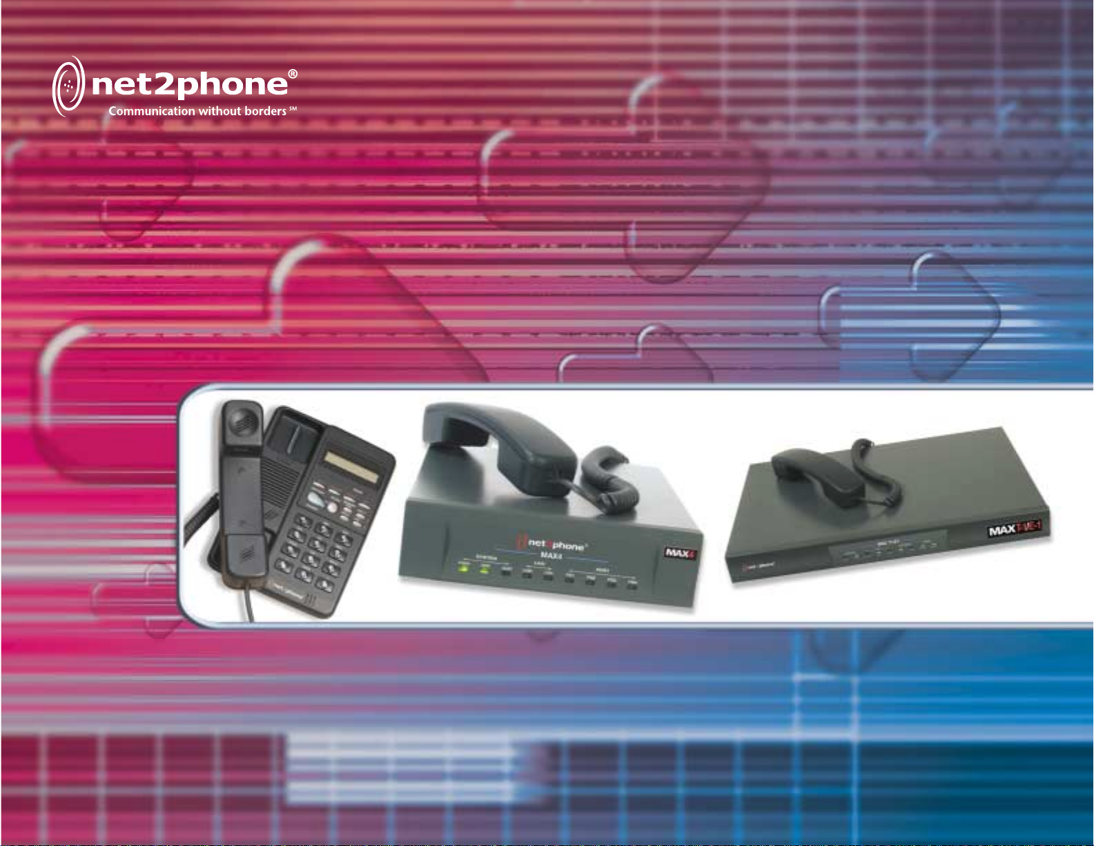
Max Sales Guide
Page 2

Contents
Introduction 2
Max™ Product Family Comparison 3
Product Snapshots 4
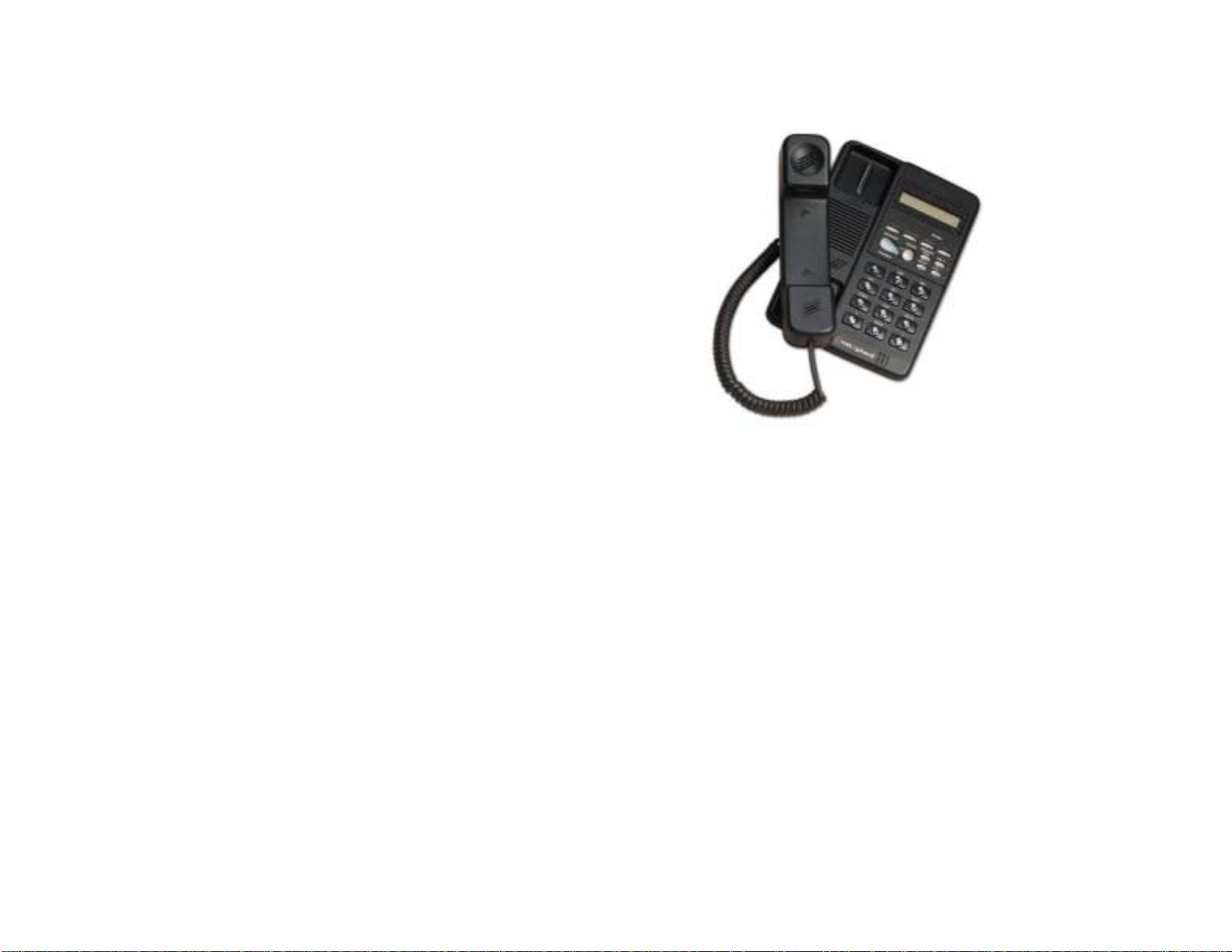
IP Phone™ 4
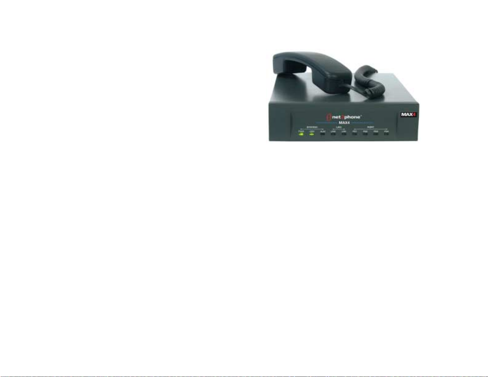
Max 4™ 5
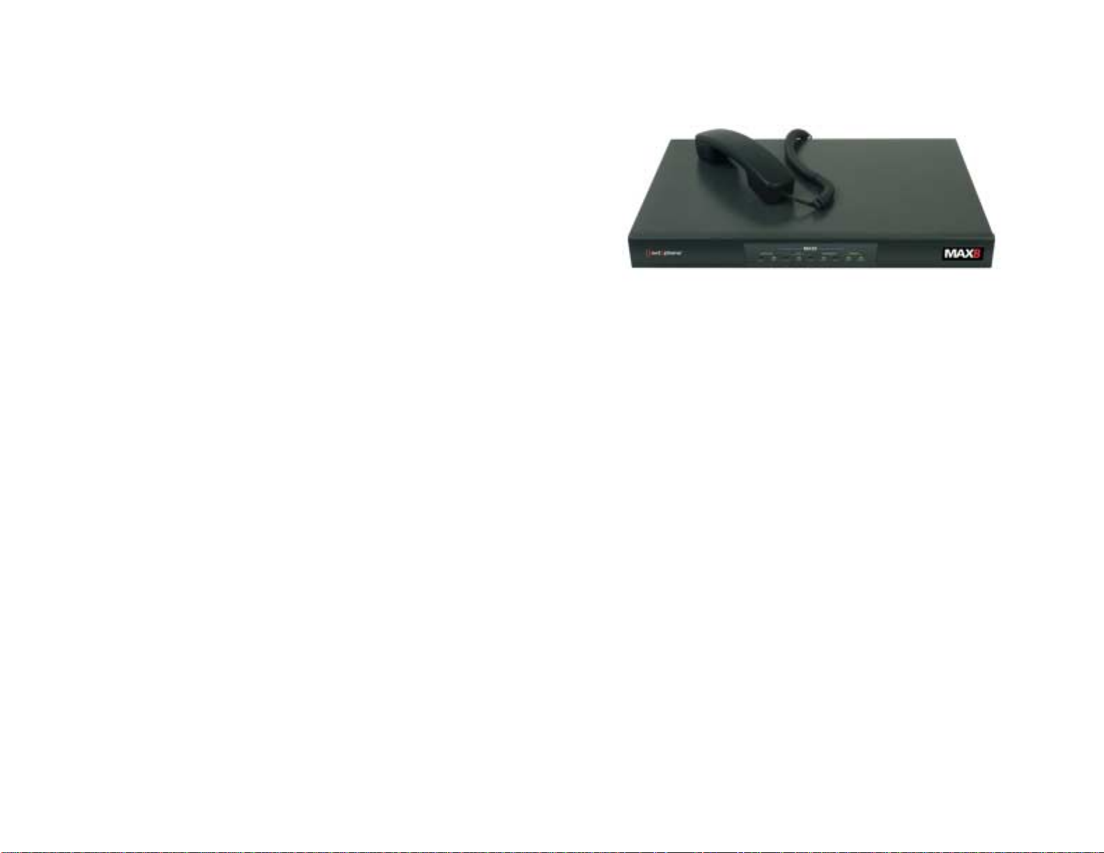
Max 8™ 6
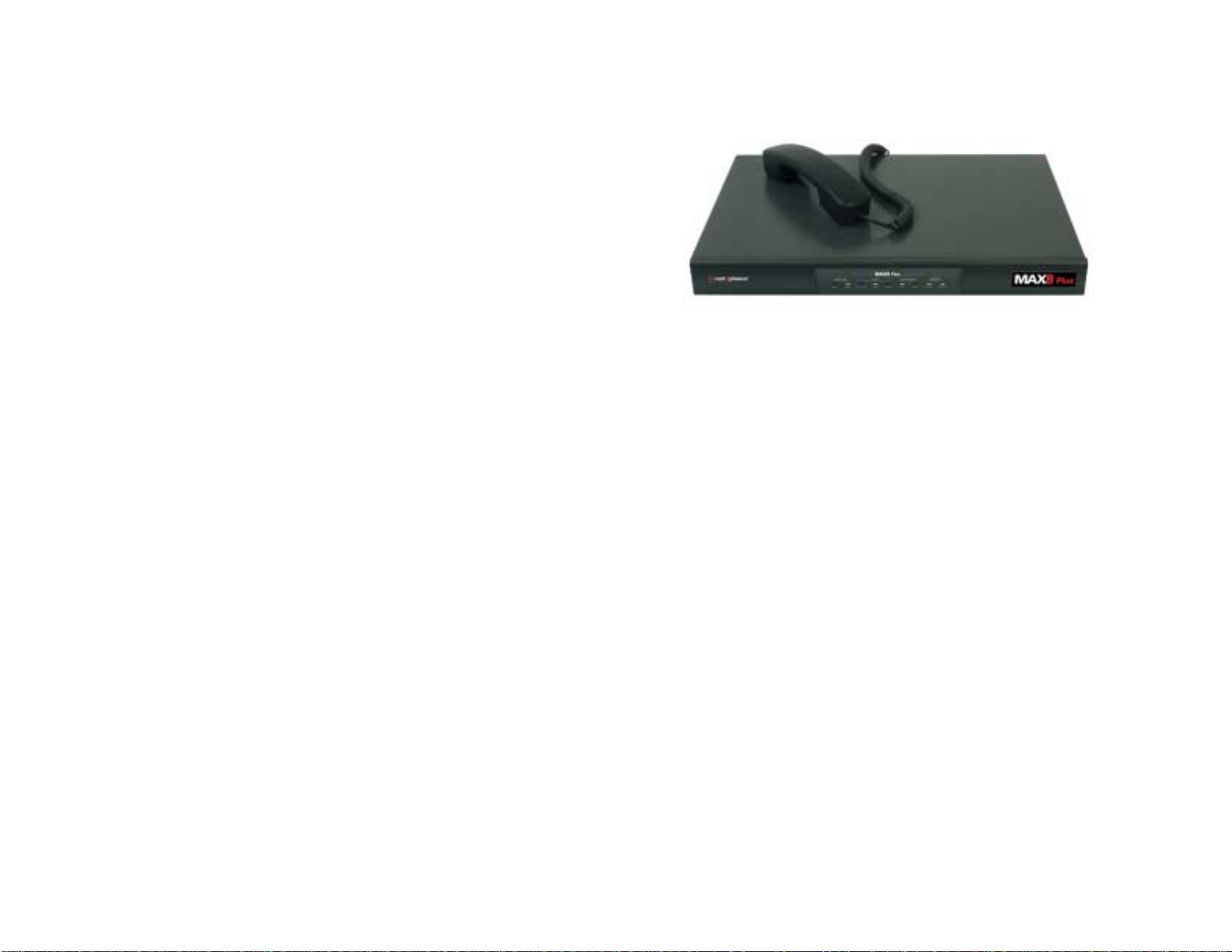
Max 8 Plus™ 7
Max 8/16™ 8
Max T1/E1™ 9
Max Series Benefits 10
Which Version of the Max Do I Need? 12
FXS vs. FXO 12
Flowchart 13
Connecting analog phones to the Max (FXS version) 14
Connecting the Max to a PBX 15
PBX basics 15
Analog PBXs (Max FXO solution) 17
Analog PBXs (Max FXS solution) 18
Digital PBXs (Max T1/E1 solution) 19
Application Diagrams 20
Calling from one Max to another 20
Hotel/Motel or Internet Café Application 21
Reference 22
Frequently Asked Questions 22
Technical Specifications 24
Max Bandwidth Requirements 30
VoIP Overview 31
Glossary 32
Contacts 39
1
Page 3

Introduction
Net2Phone® is recognized as the first company to bridge the Internet with the public switched telephone
network (PSTN), currently routing millions of VoIP (Voice over Internet Protocol) minutes daily,
transmitted by thousands of customers worldwide. Net2Phone delivers voice and enhanced services over
IP networks for businesses, telecommunications companies and consumers worldwide and is now rolling
out a sophisticated class of business products.
These products feature solutions for a variety of corporate environments, ranging from the IP Phone™,
perfect for a SOHO or single office user, to the Max T1/E1™, which connects to a digital PBX and can
support an office of over 100 users.
The Max™ gateway technology provides the ability to make inexpensive business calls over Net2Phone’s
managed IP network, bypassing much of the traditional phone network. By simply connecting these
devices to a LAN or any Ethernet connection, corporate customers can now call or fax anywhere in the
world at incredibly low rates and also utilize a new suite of business level telecommunication services.
As these products integrate seamlessly with a current corporate LAN and phone system, the return on
investment can be easily measured and quickly realized. No additional infrastructure is necessary. In
fact, the addition of these products can actually extend the life of a company’s PBX system.
2
Page 4
Max™ Product Family Comparison
The versatile Max series can support a wide range of office environments. The product line starts with the
Max 4, which is ideal for offices with up to 16 users.* The series features scalable solutions all the way to
the Max T1/E1 that can support users on a digital PBX system. The Max series connects to the Ethernet
port on a network (LAN or DSL/cable modem/ISDN with router). Then, it simply integrates with or
compliments a current phone system by accepting standard analog phones/faxes or connecting to a PBX
system.
Product # of Ports # of Users
Interface Configuration
Supported*
Max 4™ 4 16 FXS only 4 FXS
Max 8™ 8 32 FXS only 8 FXS
Max 8 Plus™ 8 32 FXS or FXO 8 FXS or 8 FXO or 4
FXS + 4 FXO
Max 8/16™ 8/16 32/64 FXS or FXO Customizable
Max T1/E1™ 24 (T1)/30
(E1)
96/120 Digital 24(T1)/30(E1) virtual
ports
*Based on calling patterns of 4-1. For example, this is assuming approximately one out of every four
people in the office would be using the phone at a given time. Calling patterns may be heavier or lighter
in certain environments.
3
Page 5
Product Snapshots
IP Phone™
Primary Customers:
SOHO, satellite office or single user in
a corporate environment (ease of
installation allows for end user setup)
Network Interface:
• 10BaseT interface (connects to LAN
or DSL/cable modem/ISDN with
router through Ethernet port)
• RJ-45
Item #: 401-7601
UPC Code: 685343-07601-3
4
Page 6
Max 4™
Primary Customers:
Small businesses, satellite offices, call
centers
Telephone Interface:
• Features four RJ-11 ports to
accepts up to four standard
(analog) phones or fax machines
• Can also connect to a PBX or KPS
through the analog trunk card
(COIC/COIB)
• FXS only
Network Interface:
Item #: 404-7704
UPC Code: 685343-07704-1
• 10/100BaseT
• RJ-45 connection
5
Page 7
Max 8™
Primary Customers:
Small businesses, satellite offices and
call centers not necessarily concerned
with adding additional users to the
same unit in the future
Telephone Interface:
• Features eight RJ-11 ports to
accept up to eight standard
(analog) phones or fax machines
• Can also connect to a PBX or KPS
through the analog trunk card
(COIC/COIB)
• FXS only
Network Interface:
• 10/100BaseT
• RJ-45 connection
Item #: 408-7702
UPC Code: 685343-07702-7
6
Page 8
Max 8 Plus™
Primary Customers:
Small businesses, satellite offices and
call centers, especially those looking to
integrate the unit with the analog
connections on a PBX
Telephone Interface:
• Features eight ports (8 FXS or 8 FXO
or 4 FXS + 4 FXO) for flexibility in
connecting to the analog
connections on a PBX
• FXO ports enable integration with a
PBX/KPS through an analog line card
(SLIC/SLIB)
Item #: 404-7705
UPC Code: 685343-07705-8
• FXS ports accept standard (analog)
phones and/or fax machines or also
connect to an analog trunk card
(COIC/COIB) of a PBX
Network Interface:
• 10/100BaseT
• RJ-45 connection
7
Page 9

Max 8/16™
Primary Customer:
Businesses looking for flexible connectivity
options and the ability to expand usage
Telephone Interface:
• Features eight ports (customizable in any
combination of FXS or FXO) for flexibility
in connecting to the analog connections
on a PBX
• Can add an eight port upgrade for a total
of 16 ports (item # 408-7708)
• FXO ports enable integration with a
PBX/KPS through an analog line card
(SLIC/SLIB)
• FXS ports accept standard (analog)
phones and/or fax machines or also
connect to an analog trunk card
(COIC/COIB) of a PBX
Network Interface:
• 10BaseT
• RJ-45 connection
8
Item #: 408-7701
UPC Code: 685343-07701-0
Page 10

Max T1/E1™
Primary Customer:
Corporations looking to integrate the
unit with a digital PBX system
Telephone Interface:
• Connects to a digital PBX through the
T1 or E1 card
• Digital connection enables 24 (T1) or
30 (E1) simultaneous calls
Network Interface:
• 10BaseT
• RJ-45 connection
Item #: 408-7901
UPC Code: 685343-07901-4
9
Page 11

Max™ Series Benefits
The benefits of the Max series include:
1) Reduced rates on calls to phones or faxes anywhere in the world
2) Even greater savings on calls from one Net2Phone device to another
3) Easily added to a corporate network and seamlessly interfaces with a current phone system
4) Provides a platform for value-added telephony services
5) Simple solution for end-user, who will not have to learn a complicated new phone system
6) Improved call quality versus standard VoIP calling
1) Reduced rates on calls to phones or faxes anywhere in the world
With the Max, low-cost calls can be placed to any phone or fax machine in the world. The caller and the
receiver of the call need not be on the same network or have the same hardware in order to realize
savings. Corporations can dramatically reduce their domestic and international communication costs,
saving up to 70%.
2) Even greater savings on calls from one Net2Phone device to another
Calls placed from any Max or Net2Phone IP Phone to another are billed at an extremely low per minute
rate. With this in mind, corporations with overseas or satellite offices can place a Max in each office, or an
IP Phone in a single-user office, to experience even greater savings. So, in addition to the cost-savings on
calls to any phone in the world, these products enable even greater savings for calls from one device to
another.
3) Easily added to a corporate network and seamlessly interfaces with a current phone system
Very simply, a business can reap the cost-saving benefits of the Max without upsetting their current
infrastructure. The Max connects seamlessly to an existing corporate LAN/Ethernet port and can be easily
integrated into a PBX system. By ensuring high-quality calling without additional investment in
infrastructure, corporations can easily measure and realize a fast return on investment. (Please see Max
Bandwidth Requirement chart on page 30 for more details on connectivity options).
10
Page 12

4) Provides a platform for value-added telephony services
In addition to low-cost calling, the Max provides a gateway to a host of value-added telephony services.
Current and future services include voice activated dialing, unified messaging, voice email retrieval, global
“800” numbers and remote dial-in.
5) Simple solution for end-user, who will not have to learn a complicated new phone system
Whether a user is calling from a standard phone connected to the Max or a phone on the PBX that is
integrated with the Max, their calling experience is seamless. Normally, users just need to dial a specific
digit to access the Max, much like they would normally dial a “9” to access the PBX. In this way,
productivity is not lost in the process of learning a complicated new phone system. The PBX can also be
programmed to route long distance calls automatically through the Max, making the dialing process
seamless to the end user.
6) Improved call quality versus standard VoIP calling
As calls are routed over Net2Phone’s private network and not just the public Internet, the quality of
service is greatly improved. The Max also features G.168 echo cancellation technology, further improving
the call quality.
11
Page 13

Which Version of the Max™ Do I Need?
FXS vs. FXO
Feature FXS FXO
Can attach standard analog
_
phones or faxes
Can attach to a PBX through an
_
analog trunk card
Can attach to a PBX through an
_
analog line card
Features IVR functionality _
Supports inbound PSTN calling _
Can support a Hospitality
_
Management System (HMS) billing
system
Supports inbound calling from
__
another Max or IP Phone
Supports remote calling _
12
Page 14
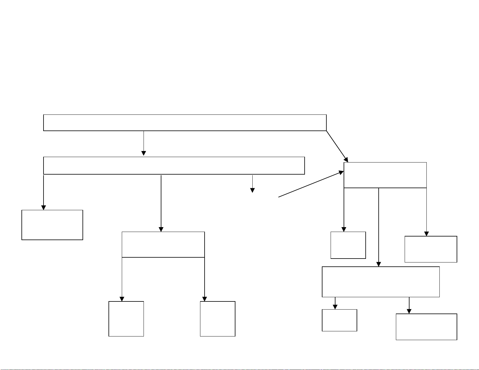
Flowchart
)
First, you must qualify that your customer has:
1) A network
2) At least 17 Kbps throughput per line
3) A static or DHCP Internet connection
Then, you need to ask:
Will you be connecting the Max to a PBX or to analog phones?
PBX
Analog phones/Fax
machines
What type of PBX do you have?
Digital PBX (with
T1/E1 connection
Max T1/E1
How many users
are in the office?
32 and
this #
will
not
grow
Max 8
Plus
(FXO)
PBX/KPS w/
Analog Line
Card
(SLIC/SLIB)
32 and
this #
may
grow
Max
8/16
(FXO)
PBX/KPS w/
Analog Trunk Card
(COIC/COIB)
How many users
are in the office?
16 or
less
Max 4
(FXS)
32
and
this
# will
not
grow
Max 8/16
(FXS)
Do you want the flexibility
to be able to change to
FXO ports in the future?
No Yes
Max 8
Max 8 Plus
(FXS)
32 and
this #
may
grow
13
Page 15
Connecting analog phones to the Max™ (FXS version)
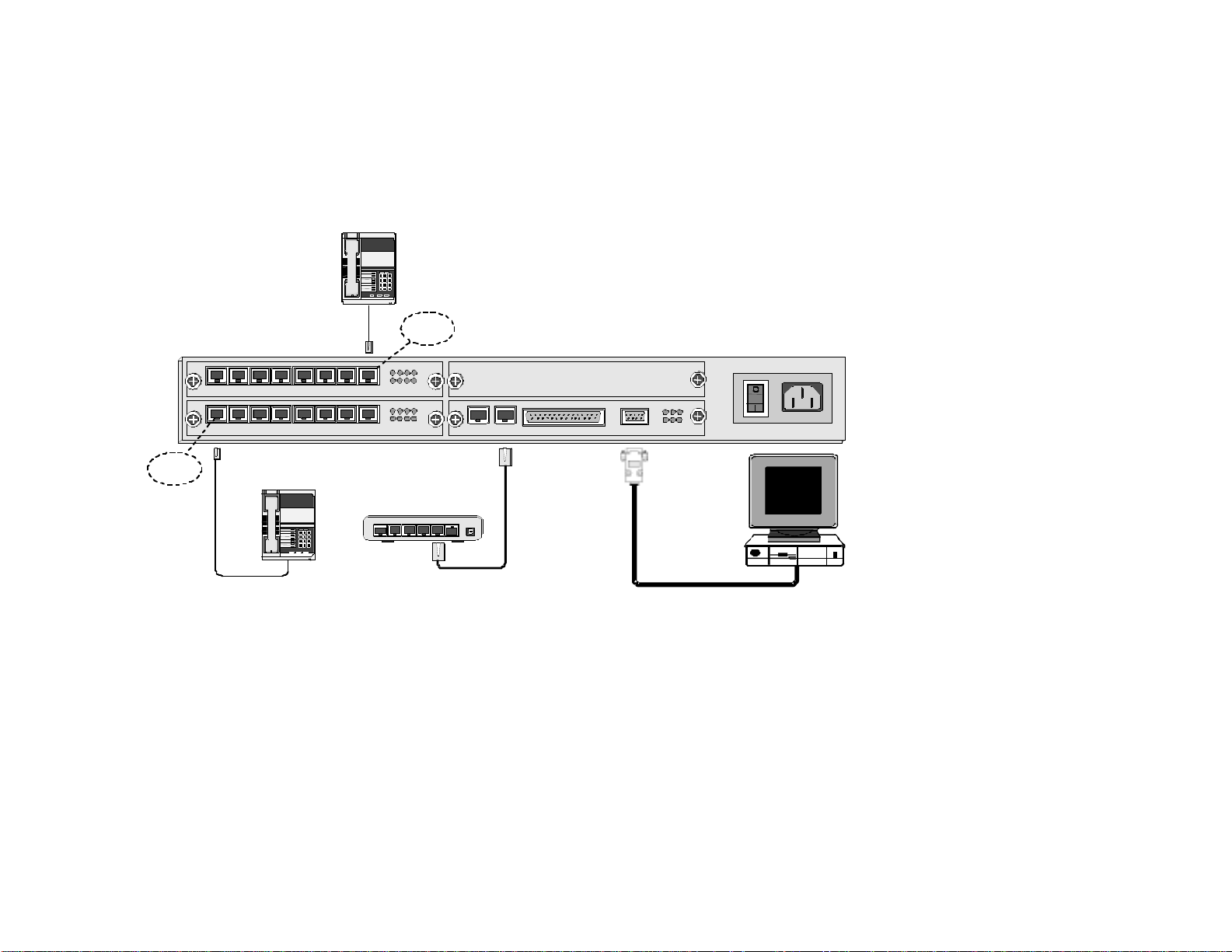
If your customer plans to connect analog phones or fax machines to the Max, they would need an FXS (Foreign Exchange Station) version.
Standard analog phones simply connect to an FXS version of the Max with an RJ-11 cable. The diagram below shows all the connections
necessary to operate an FXS version of the Max:
Analog
Telephone
12 3
45 6
78 9
8#
*
FXS Port
1 2 3 4
1 2 3 4 5 6 7 8
AVU
1 2 3 4 5 6 7 8
AVU
5 6 7 8
1 2 3 4
5 6 7 8
BLK
OPR LTX STX
SYN LRX SRX
CONSOLESERIALLANE1/T1MPU
PWR AC 110-240V
FXS Port
Analog
Telephone
Hub
or
Switch
123
456
789
*8#
4 3 2 1 Uplink
5
Power
1 Telephone/Fax Connections
Standard analog telephones and fax machines connect to the analog FXS ports with RJ-11 cables.
2 LAN Ethernet Connections
To connect the Max to the LAN, plug the RJ-45 LAN jack from the hub or router into the LAN port on the Max.
3 PC Connection
To initially configure the Max, you can either:
a) Connect it to a PC by using a 9-pin RS-232C cable to connect the PC’s COM1 serial port to the Max console (pictured above) OR
b) Use a telephone connected to an FXS port to acquire an IP address. Then, you will need to use a PC for the initial account setup. This PC should be on the
same network but does not have to be connected directly to the Max.
4 AC Power Connection
Plug the Max into a power outlet.
Note: When only analog phones are connected, the FXS version of the Max does not support inbound PSTN calling, but
you can receive calls (via *72) from other Max units.
14
Page 16

Connecting the Max™ to a PBX
By connecting the Max to a PBX, additional features such as inbound PSTN calling and remote calling can be supported.
Basically, an analog PBX would require an FXS or FXO version of the Max. The primary determinant between FXS and FXO is
the type of card and available ports present on the PBX. On the other hand, a digital PBX would require the Max T1/E1. To
better understand all of the terminology involved, below is a basic PBX overview as it relates to the Max.
PBX basics
As you know, a PBX (Private Branch Exchange) is a phone system that takes a number of telephone lines from the outside
world and makes them available throughout an office. Users on a PBX share a certain number of outside lines within the
company and have to dial a special number, such as “9”, to access an outside line. Theoretically, not everyone within the
company uses an outside line at the same time, so the number of outside lines on the PBX is usually equal to some number less
than the number of employees. In this way, utilizing a PBX is more cost effective than connecting an external telephone line to
every telephone within an organization. Here are a few key terms you should be familiar with:
Analog Line Card An analog line card is a type of card featured on a PBX. The analog line card is used to connect an
FXO version of the Max. Another name for an analog line card is a SLIC/SLIB (Subscriber Line
Interface Card/Board).
Analog Trunk Card An analog trunk card (ATC) is another type of card featured on a PBX. The analog trunk card is
used to connect an FXS version of the Max. Another name for an analog trunk card is a COIC/COIB
(Central Office Interface Card/Board).
CO/CO Line/Trunk Line CO stands for Central Office, typically the location where the phone company stores their telco
equipment. CO lines are physically run from this location to a business or home. A CO line is a
line with a phone number (i.e. 973-412-4444) that carries calls into and out of a residence or
business. In a business environment, these lines are typically connected to a PBX, allowing phones
connected to the PBX to carry phone calls into and out of the building.
Extension Lines Extension lines refer to the individual telephone stations on a PBX that have a separate extension
number. An extension line is a line to the PBX, not an actual outside telephone line. Extension
lines can be connected to a multi-port extension card that is attached to the PBX. When one
extension is used to dial another, the PBX acts as a voice router to transport and carry the call to
the appropriate extension.
15
Page 17

Hunt Group A hunt group refers to a group of related phones that can be set up to share particular lines. For
example, a hunt group can be established when connecting a Max FXO unit to a PBX. When
multiple FXO ports on the Max are connected to the PBX, the phones on the PBX can be
programmed to share these lines. Users would dial their hunt group code, such as “4000”, to have
access to any of the available lines. The PBX accomplishes this by handing off the calls to the next
available FXO port on the Max. The user would only receive a busy signal if all of the lines of the
hunt group were busy. Or, in this case, the PBX could be programmed to automatically hand the
call off to the traditional PSTN phone system. A hunt group can also be established for a Max FXS
unit connected to a PBX.
IVR IVR (Interactive Voice Response) refers to the voice message options that can greet a Max FXO
caller. For example, a Max connected to a PBX extension can be set to greet the caller with a
message such as “Welcome to Net2Phone”, can require a password prior to granting access, or be
set to simply provide a standard dial-tone once accessed. As mentioned above, only FXO ports
provide IVR access. Instructions for customizing the IVR, such as providing personalized voice
messages in another language, are included in the user documentation.
Key System A key system is a telephone system that, for our purposes, is similar to a PBX in most respects.
One of the major differences, however, is that each extension on the system has buttons to directly
reach an outside line. Users on a key system do not have to dial a special number, such as “9”, to
reach an outside line. Key systems are sometimes referred to as a KTS (Key Telephone System) or
a KPS (Key Phone System). The Max product line has the same connection requirements for a Key
System as a PBX.
RJ-11 RJ-11 refers to the physical connection utilized in standard analog phones. An RJ-11 cord connects
an analog phone to a standard, home phone jack.
16
Page 18
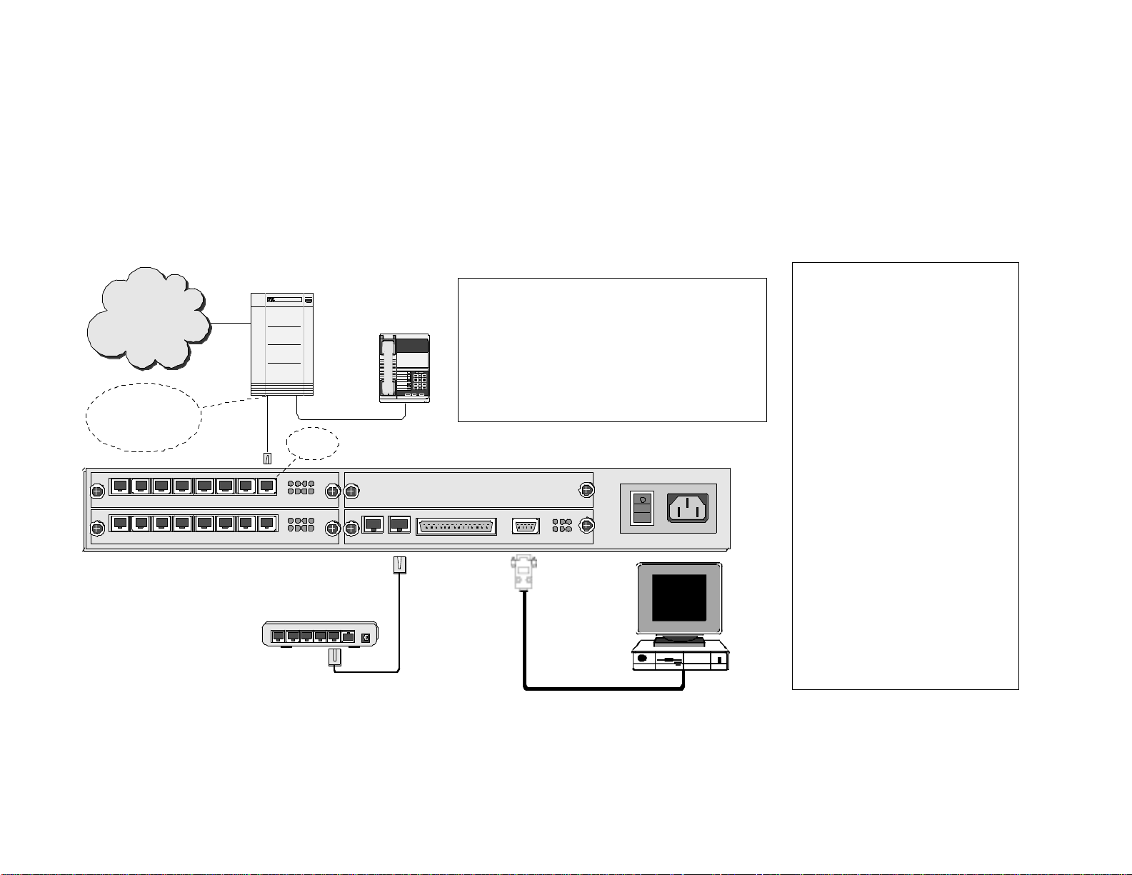
Analog PBXs (Max™ FXO solution)
T
T
If your customer has an analog PBX with an available analog line card (SLIC/SLIB), the optimal Max solution is an FXO (Foreign
Exchange Operator) version. To connect an FXO version of the Max to an analog PBX, simply use RJ-11 cables to connect the
analog line card to the FXO ports on the Max. If only one FXO port on the Max is connected to the PBX, all of the users on the
PBX will be sharing this one line. If more lines are desired, simply connect multiple FXO ports to the PBX. Then, a hunt group
can be established so that the users are sharing multiple lines. The diagram below shows all the connections necessary to
operate an FXO version of the Max:
1 PBX Connections
PBX: Private Branch Exchange
PSTN
PBX
Switch
PBX
Telephone
PSTN: Public Switched Telephone Network
SLIC/SLIB: Subscriber Line Interface Card/Board
123
456
789
8#
*
Connects to SLIC
(SLIB or SLT) card,
FXS card or Station
card of PBX
1 2 3 4 5 6 7 8
AVU
1 2 3 4 5 6 7 8
AVU
1 2 3 4
5
6 7
1 2 3 4
5
6 7
FXO
Port
8
8
BLK
Hub
or
Switch
Power4 3 2 1 Uplink5
SLT: Single Line Terminal or Telephone
(analog telephone)
Trunk /CO Line: Line from Central Office switch
OPR LTX STX
SYN LRX SRX
SERIALLANE1/T1MPU
CONSOLE
PWR AC 110-240V
3
Connect the analog line card to the
FXO ports on the Max with RJ-11
cables.
2 LAN Ethernet Connections
o connect the Max to the LAN,
plug the RJ-45 LAN jack from the
hub or router into the LAN port on
the Max.
3 PC Connection
o initially configure the Max, you
must connect it to a PC. Use a 9pin RS-232C cable to connect the
PC’s COM1 serial port to the Max
console. (Note: If there is an FXS
port also available on the Max, you
can configure it with a phone
connected to the Max and a PC on
the same network, as outlined
earlier)
4 AC Power Connection
Plug the Max into a power outlet.
Note: IVR functionality is
available with an FXO version of
the Max.
17
Page 19
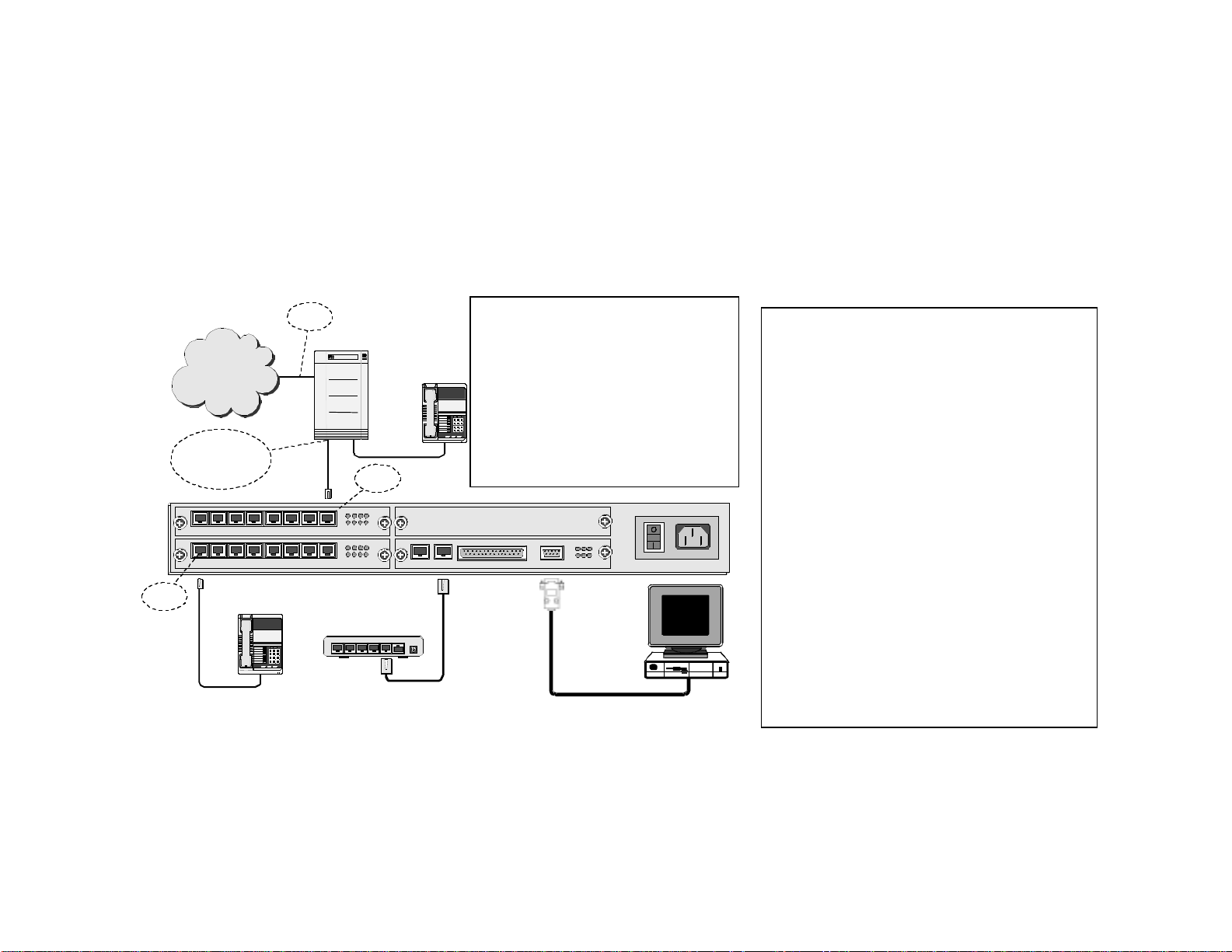
Analog PBXs (Max™ FXS solution)
If your customer has an analog PBX with an available analog trunk card (ATC, COIC/COIB), an FXS (Foreign Exchange Station)
version of the Max can be used. To connect an FXS version of the Max to an analog PBX, simply use RJ-11 cables to connect
the analog line card to the FXS ports on the Max. If only one FXS port on the Max is connected to the PBX, all of the users on
the PBX will be sharing this one line. If more lines are desired, simply connect multiple FXS ports to the PBX. Then, a hunt
group can be established so that the users are sharing multiple lines. The diagram below shows all the connections necessary
to operate an FXS version of the Max with an analog PBX:
Connects to COIC
(COIB or Trunk) card,
or FXO card of PBX
AVU
AVU
FXS Port
CO Line
PSTN
1 2 3 4 5 6 7 8
1 2 3 4 5 6 7 8
Analog
Telephone
123
456
789
8#
*
12 34
56 78
12 34
56 78
PBX
Switch
FXS Port
Hub
or
Switch
BLK
Power4 3 2 1 Uplink5
PBX
Telephone
COIC/COIB: Central Office
Interface Card/Board
PBX: Private Branch
Exchange
PSTN: Public Switched
123
456
789
8#
*
Telephone Network
Trunk/CO Line: Line from Central
Office switch
OPR LTX STX
SYN LRX SRX
CONSOLESERIALLANE1/T1MPU
3
PWR AC 110-240V
1 PBX Connections
Connect the analog trunk card to the FXS ports
on the Max with RJ-11 cables.
2 LAN Ethernet Connections
To connect the Max to the LAN, plug the RJ-45
LAN jack from the hub or router into the LAN
port on the Max.
3 PC Connection
To initially configure the Max, you must connect
it to a PC. Use a 9-pin RS-232C cable to connect
the PC’s COM1 serial port to the Max console.
(Note: You can configure an FXS version with a
phone connected to the Max and a PC on the
same network, as described earlier)
4 AC Power Connection
Plug the Max into a power outlet.
Note: IVR functionality is not available with an
FXS version of the Max. If the PBX only has an
available analog trunk
card and this feature is
required, an analog line card must be added and
an FXO version of the Max must be used.
18
Page 20
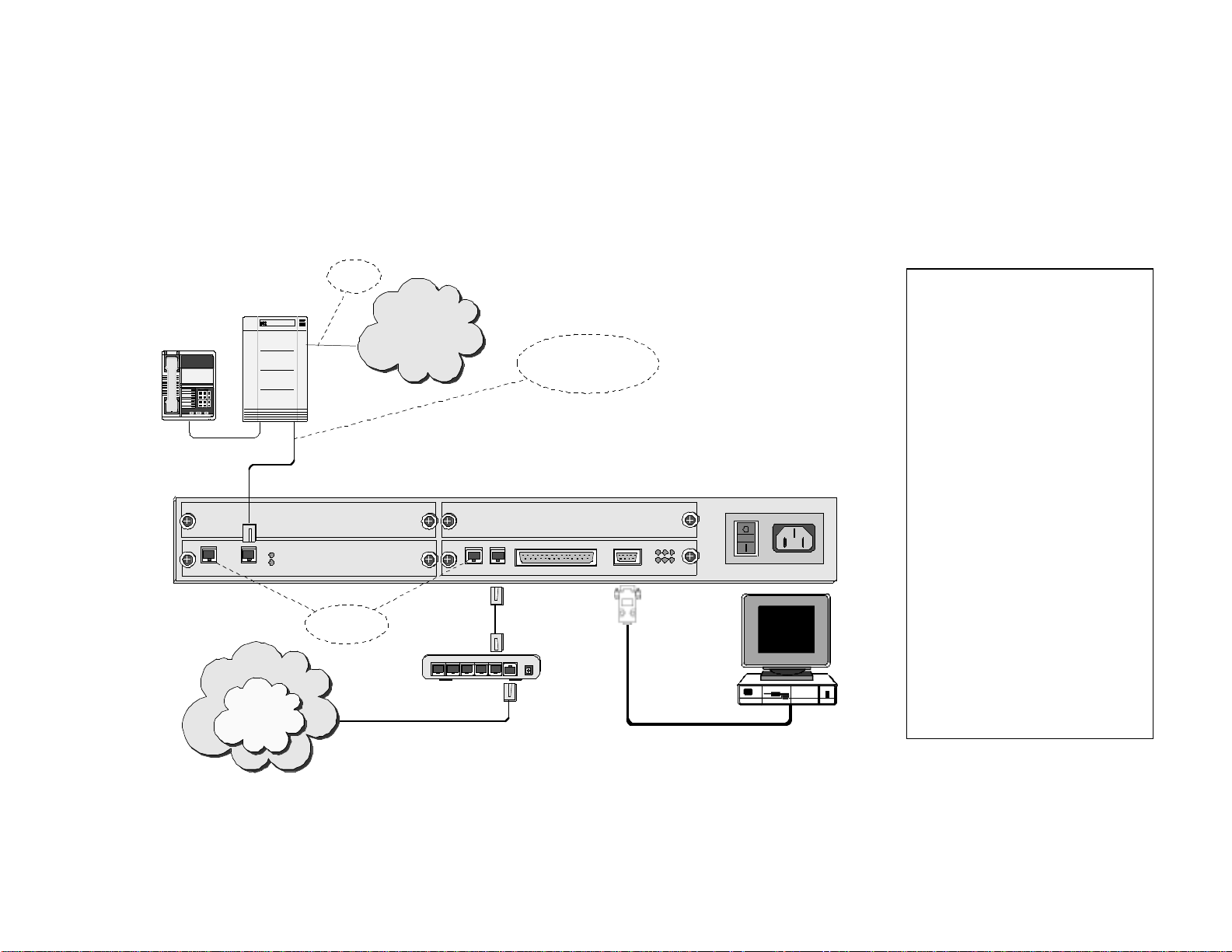
Digital PBXs (Max T1/E1™ solution)
T
T
Most new PBXs are digital. If your customer has a digital PBX, the optimal Max solution is the Max T1/E1. To connect the Max
T1/E1 to a digital PBX, simply use an RJ-48 cable to connect the T-1/E-1 port on the Max to the T-1/E-1 port on the PBX. With
a Max T1/E1, users on the PBX share either 24 (T-1 connection) or 30 (E-1 connection) virtual lines. For example, if there are
50 phones on the PBX and the Max is connected to an E-1, these 50 users will be sharing 30 lines. The diagram below shows
the basic connections of a Max T1/E1 in a digital PBX environment:
CO Line
1 PBX Connections
With an RJ-48 cable, connect the
right-side T-1/E-1 port on the Max
PBX
Telephone
PSTN
PBX
Switch
123
456
789
8#
*
RJ-48 shielded cable -
connects to T1/E1 interface
on PBX
to the T-1/E-1 port on the PBX.
2 LAN Ethernet Connections
o connect the Max to the LAN,
plug the RJ-45 LAN jack from the
hub or router into the LAN port on
the Max.
3 PC Connection
o initially configure the Max, you
must connect it to a PC. Use a 9pin RS-232C cable to connect the
PC’s COM1 serial port to the Max
BLK
E1/T1 E1/T1
DVU
SYN 1
SYN 2
BLK
SERIALLANE1/T1MPU
CONSOLE
OPR LTX STX
SYN LRX SRX
PWR AC 110-240V
For factory
use only
432
Internet
5
Net2Phone
Network
1 Uplink
Router
Power
3
console.
4 AC Power Connection
Plug the Max into a power outlet.
Note: Certain digital PBXs may
feature analog ports in addition to
the T-1/E-1 interface. If this is the
case, it is possible to connect a
Max FXO or FXS version to the
digital PBX, depending on whether
there is an available analog trunk
card or analog line card.
19
Page 21
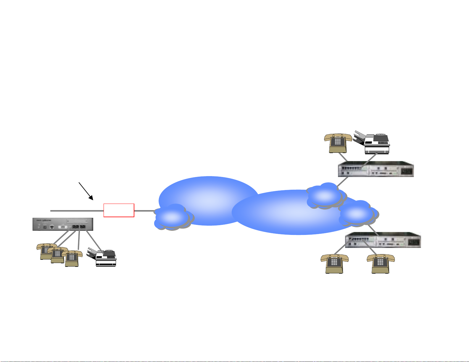
Application Diagrams
Calling from one Max™ to another
The following diagram shows how branch office communications can be established through the Max to cut
costs dramatically. Calls from one Max to another are billed at the same low per minute rate, no matter
where in the world they are being made.
London
Net2Phone Max
an Francisco
Router
ISP
Net2Phone
Net2Phone Max
20
ISP
Net2Phone Max
ISP
Hong Kong
Page 22
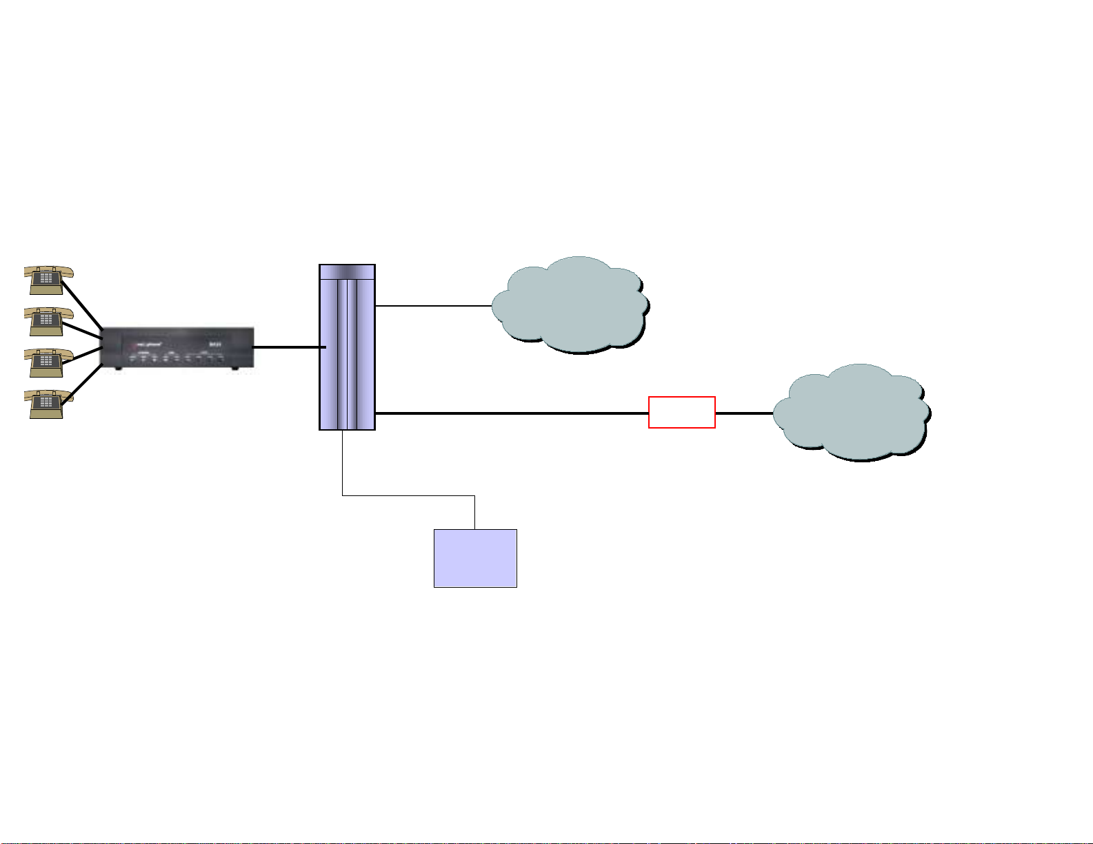
Hotel/Motel or Internet Café Application
r
The following diagram shows how a Max unit can be integrated into a hotel/motel or Internet Café
environment with a PBX system to take advantage of an existing billing system.
Analog
PBX/KTS
CO line
PSTN
SMDR/CDR
from PBX
(Subscriber Message
Detail Recording)
HMS
21
Route
N2P Network
Hospitality Management
System (HMS)
(Connects PBX CDR output
to billing systems)
Page 23

Reference
FAQs
1) What is the FXS functionality of the Max?
FXS stands for “Foreign Exchange Station”. Very basically, you can plug standard analog phones into a
Max FXS unit. The FXS version of the Max does not support inbound PSTN calling, but you can receive
calls (via *72) from other Max units. It is possible to attach FXS lines to a PBX through an analog
trunk card (COIC/COIB).
2) What is the FXO functionality of the Max?
FXO stands for “Foreign Exchange Operator”. Basically, FXO allows you to connect the Max to a PBX
through an analog line card (SLIC/SLIB). With an FXO unit, inbound PSTN calls and remote calling are
supported.
3) What does T-1/E-1 mean?
T-1/E-1 is the standard digital interface for high capacity transmission of telephony and data
communications. North America uses the T-1 standard, which supports up to 24 simultaneous calls on
the Max, while Europe utilizes the E-1 standard, which supports up to 30 simultaneous calls. The T1/E-1 interface is a single port on the Max.
4) How do I connect a Max T1/E1 to a PBX?
Very simply, connect the T-1/E-1 port on the Max unit to the T-1/E-1 port on the PBX with an RJ-48
cable.
5) What bandwidth is required to use the Max?
The Max requires 17k bandwidth per line in order to maintain the Quality of Service (QoS).
6) How do I upgrade the Max?
Upgrading the Max unit is a relatively quick and easy process. Connect to the Web interface, click on
“upgrade” and follow the instructions. During the upgrade procedure, no calls should be made through
the Max. Upgrade times vary depending on available bandwidth, but normally take no longer than five
minutes.
22
Page 24

7) Can I call from one Max or IP Phone to another?
Yes. You can place calls from any one of the Max units to another. You can also call from the IP Phone
to a Max and vice versa.
8) How do I call from one Max to another?
To call from one Max unit to another, dial “*72” followed by the account number of the person you are
calling. If the device is connected to a PBX, the PBX can be programmed to allow for simpler dialing
conventions. For example, if the user calls a particular account number frequently (such as a Max in a
satellite office), the PBX can be programmed for speed dialing.
9) Can I call any number through the Max (i.e. 911)?
Please be aware that special emergency and informational numbers (i.e. 411, 611, 911, 0) cannot
normally be accessed through the Max. However, if you have a Max with at least one FXO port, it can
be configured so that these calls are routed through the PSTN.
10) What issues will the presence of a proxy raise?
If a proxy is present, the Max unit will not operate.
11) If I already have a Max and want to add more, what are the installation issues involved?
You would add additional Max units to a network just as you would add additional computers to a
network. Make sure there is enough bandwidth present and the appropriate IP addresses are
available.
12) What will happen if all of the lines from the Max are in use? Can I still place a call?
The PBX can be programmed so that if all of the Max lines are in use, calls will be routed through
the PSTN. If this happens frequently, it may be time to add an additional Max or additional ports in
the case of the Max 8/16.
13) Will the Max work with LCR (Least Cost Routing) systems?
FXS and T1/E1 versions of the Max will work in conjunction with PBXs that feature least cost routing.
23
Page 25

Technical Specifications
IP Phone™
LAN Interface 10BaseT, RJ-45
Communications Protocol
Voice Compression G.723.1
Power Supply
Operation Temperature
Operation Humidity 5 ~ 95%
Graphical Display 3” x 2” LCD
Physical Size (L x W x H) 8.5” x 7.5” x 3”
Weight 2 lbs.
TCP/IP
DHCP client or static IP addressing
12V AC
1000 mA
5 ~ 40° C
24
Page 26
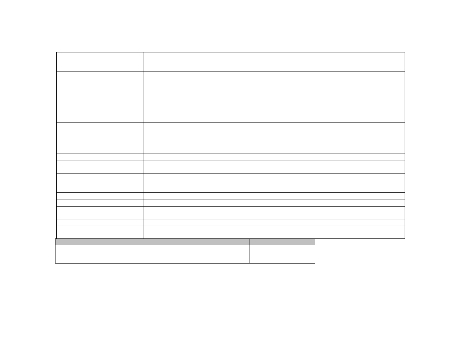
Max 4™
Analog Voice Interface FXS, RJ-11, 4 ports
LAN Interface
Serial Interface EIA-232 {old RS-232C}, DB-9, 1 port Asynchronous serial communication at 19200bps
LED indicators
VoIP protocol Net2Phone propriety protocol
Voice Processing Capabilities
{compression/decompression}
{QoS related capabilities}
Management interface Command line interface via console port or telnet client Web interface via any Web browser
Physical Size (H x W x D) 55 x 210 x 256 mm
Weight 1.6 Kg.
Input power
Main processor Motorola MPC855T
Operation temperature
Storage temperature
Operation humidity 5 ~ 95%, non-condensing
Noise level 15 dB @ 1 m
Ringer Equiv. No. 0.5B
External AC/DC Adapter
LED Meaning LED Meaning LED Meaning
PWR Power OPR Operational ALM Alarm
LINK Link active LRX Receive data PS1 FXS port 1 status
PS2 FXS port 2 status PS3 FXS port 3 status PS4 FXS port 4 status
10/100BaseT, RJ-45, 1 port
{Ethernet/Fast Ethernet auto-detection}
One system power indicator
One active status indicator for system
One alarm indicator for system malfunction
One active status indicator for each analog voice port
One LAN link indicator
One LAN data receive indicator
G.711
G.723.1
Echo Cancellation (G.168)
Voice Activity Detection
Comfort Noise Generation
-48VDC, 0.5A(max.)
External AC/DC Adapter
0 ~ 50° C
40 ~ 85° C
Input: 110~240VAC 60Hz
Output: -48VDC, 0.5A(max.)
25
Page 27
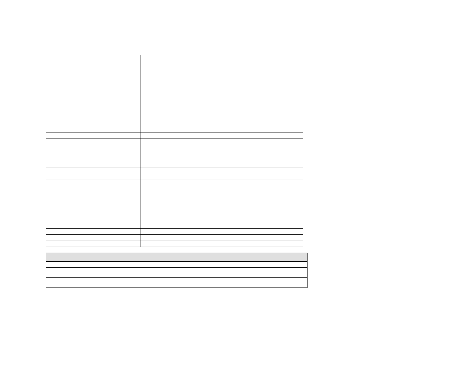
Max 8™
Analog Voice Interface FXS, RJ-11, 8 ports
LAN Interface
Serial Interface
LED indicators
VoIP protocol Net2Phone propriety protocol
Voice Processing Capabilities
{compression/decompression}
{QoS related capabilities}
Management interface
Physical Size (H x W x D)
Weight 2 Kg.
Input power
Main processor Motorola MPC855T
Operation temperature 0 ~ 50o C
Storage temperature 40 ~ 85o C
Operation humidity 5 ~ 95%, non-condensing
Noise level 15 dB @ 1 m
Ringer Equiv. No. 0.5B
10/100BaseT, RJ-45, 1 port
{Ethernet/Fast Ethernet auto-detection}
EIA-232 {old RS-232C}, DB-9, 1 port
Asynchronous serial communication at 19200bps
one active status indicator for system; one alarm indicator for
system malfunction
one active status indicator for each analog voice port; one Fast
Ethernet indicator
one LAN link indicator; one LAN data receive indicator
one serial port transmit indicator; one serial port receive
indicator
one voice transmit indicator; one voice receive indicator
G.711
G.723.1
Echo Cancellation(G.168)
Voice Activity Detection
Comfort Noise Generation
Command line interface via console port or telnet client
Web interface via any Web browser
45 x 439 x 310 mm
{mounting handles for 19 inch rack are available}
100 - 240 VAC, 1.5 A (max.),
50/60 Hz , 50 W (max.)
LED Meaning LED Meaning LED Meaning
ALM Alarm OPR Operational 10/100 Fast Ethernet
LINK Link active LRX
SRX Serial port receive
TXHW
Receive data
Voice transmit RXHW Voice receive
STX Serial port transmit
26
Page 28
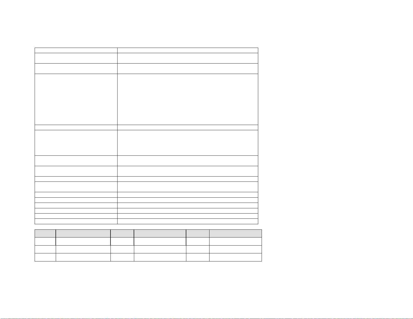
Max 8 Plus™
Analog voice interface FXS, RJ-11 (if present)
LAN interface
Serial interface
LED indicators
VoIP protocol Net2Phone proprietary protocol
Voice processing capabilities
{compression/decompression}
{QoS related capabilities}
Management interface
Physical Size (H x W x D)
Weight 2 Kg.
Input power
Main processor Motorola MPC855T
Operation temperature 0 ~ 50o C
Storage temperature 40 ~ 85o C
Operation humidity 5 ~ 95 (NOTE: non-condensing)
Noise level 15 dB @ 1 m
Ringer Equiv. No. 0.5B
10/100BaseT, RJ-45, 1 port
{Ethernet/Fast Ethernet auto-detection}
EIA-232 {old RS-232C}, DB-9, 1 port
Asynchronous serial communication at 19200bps
one active status indicator for system
one alarm indicator for system malfunction
one active status indicator for each analog voice port
one Fast Ethernet indicator
one LAN link indicator
one LAN data receive indicator
one serial port transmit indicator
one serial port receive indicator
one voice transmit indicator
one voice receive indicator
G.711
G.723.1
Echo Cancellation(G.168)
Voice Activity Detection
Comfort Noise Generation
Command line interface via console port or telnet client
Web interface via any Web browser
45 x 439 x 310 mm
{mounting handles for a 19-inch rack are available}
100 - 240 VAC, 1.5 A (max.),
50/60 Hz , 50 W (max.)
LED Meaning LED Meaning LED Meaning
ALM Alarm OPR Operational 10/100 Fast Ethernet
LINK Link active LRX Receive data STX Serial port transmit
SRX Serial port receive TXHW Voice transmit RXHW Voice receive
27
Page 29

Max 8/16™
Analog Voice Interface
Digital Voice Interface
LAN Interface
Console Interface
LED indicators
VOIP protocol
Voice Processing Capabilities
{compression/decompression}
{QoS related capabilities}
Management interface
Physical Size (H x W x D)
Weight
Input power
Main processor
Operation temperature
Storage temperature
Operation humidity
Noise level
FXS or FXO, RJ-48, 8/16 ports
T1 or E1, RJ-48, 1 port
{R2-MFC support}
10/100BaseT, RJ-45, 1 port
{Ethernet/Fast Ethernet auto-detection}
EIA-232 {old RS-232C}, DB-9, 1 port
Asynchronous serial communication at
19200bps
one active status indicator for operating
system
one active status indicator for each
analog voice port
one active status indicator for each digital
voice port
one LAN data transmit indicator
one LAN data receive indicator
Net2Phone propriety protocol
G.711
G.729.a
G.723.1
Echo Cancellation(G.168)
Voice Activity Detection
Comfort Noise Generation
Command line interface via console port
or telnet client
Web interface via any Web browser
53.5 x 439 x 300 mm
{mounting handles for 19 inch rack are
available}
Max. 5.5 kg
{depends on hardware configurations}
110-220 VAC, 1 A (max.),
50/60 Hz , 60 W (max.)
Motorola MPC860T
o
0 ~ 50
–40 ~ 85
5 ~ 95 %, non-condensing
30 dB @ 1 m
C
o
C
28
Page 30
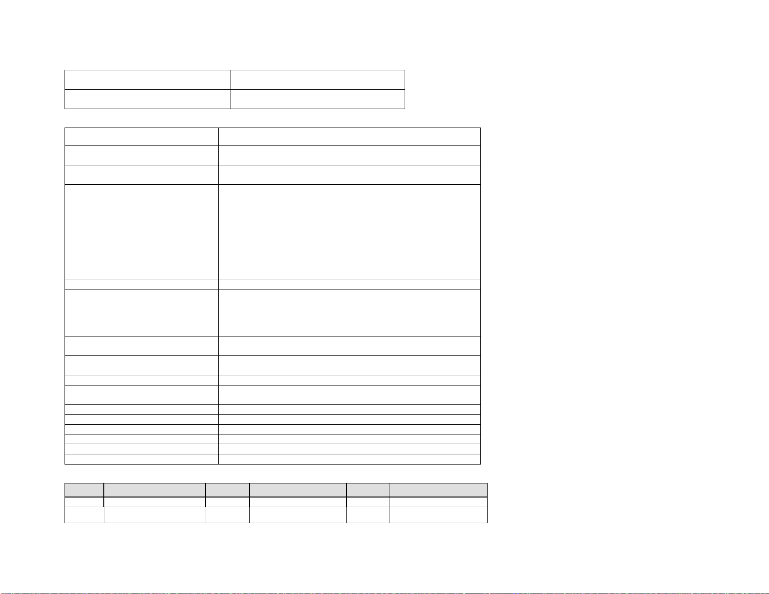
Grounding wire specification
Fuse specification
AWG18, GREEN/YELLOW
SCHURTER, T2AL250V
Max T1/E1™
Analog voice interface
LAN interface
Serial interface
LED indicators
VoIP protocol Net2Phone proprietary protocol
Voice processing capabilities
{compression/decompression}
{QoS related capabilities}
Management interface
Physical Size (H x W x D)
Weight 2 Kg.
Input power
Main processor Motorola MPC855T
Operation temperature 0 ~ 50o C
Storage temperature 40 ~ 85o C
Operation humidity 5 ~ 95 (NOTE: non-condensing)
Noise level 15 dB @ 1 m
Ringer Equiv. No. 0.5B
FXS, RJ-11 (if present)
10/100BaseT, RJ-45, 1 port
{Ethernet/Fast Ethernet auto-detection}
EIA-232 {old RS-232C}, DB-9, 1 port
Asynchronous serial communication at 19200bps
one active status indicator for system
one alarm indicator for system malfunction
one active status indicator for each analog voice port
one Fast Ethernet indicator
one LAN link indicator
one LAN data receive indicator
one serial port transmit indicator
one serial port receive indicator
one voice transmit indicator
one voice receive indicator
G.711
G.723.1
Echo Cancellation(G.168)
Voice Activity Detection
Comfort Noise Generation
Command line interface via console port or telnet client
Web interface via any Web browser
45 x 439 x 310 mm
{mounting handles for a 19-inch rack are available}
100 - 240 VAC, 1.5 A (max.),
50/60 Hz , 50 W (max.)
LED Meaning LED Meaning LED Meaning
ALM Alarm OPR Operational 10/100 Fast Ethernet
LINK Link active LRX
Receive data
STX Serial port transmit
29
Page 31

SRX Serial port receive
TXHW
Voice transmit RXHW Voice receive
30
Page 32
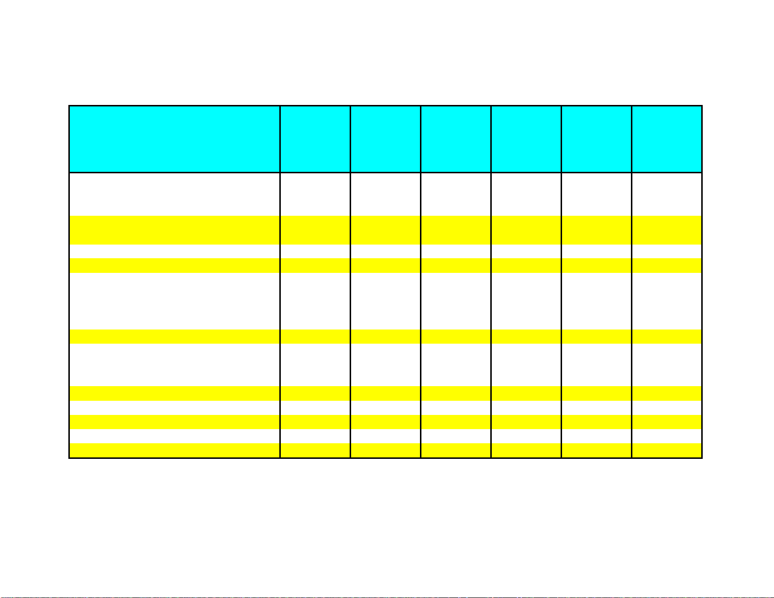
Max™ Bandwidth Requirements
Types of Broadband Services and
Connection Speeds
28.8 Kbps dial up modem 1 1 N/A N/A N/A N/A
33.6 Kpbs dial up modem (>30K actual) 1 1 N/A N/A N/A N/A
56 Kbps dial up modem (>40K actual) 2 2 N/A N/A N/A N/A
ISDN modem with 1B (64 Kbps) 3 3 3 3 3 3
ISDN modem with 2B (128 Kbps) 7 4 7 7 7 7
ISDN-BRI (IDSL) 144 Kbps 8 48888
Cable Modem 1.5M/384Kbps down/up speed 22 4 8 16 22 22
Cable Modem 4M/384 Kbps down/up speed 22 4 8 16 22 22
Satellite Modem 150K~400K down speed 8 48888
Fixed Wireless 512K~2M down speed 30 4 8 16 24/23 30
ADSL-Lite 64K~1.5M/64K~520K 3 33333
ADSL 768K/128K down/upload speed 7 4 7 7 7 7
HDSL 1.5M/128K down/upload speed 7 47777
ADSL 1.5M/384K down/upload speed 22 4 8 16 22 22
ADSL 7.1M/768K down/upload speed 45 4 8 16 24/23 30
SDSL 384K/284K down/upload speed 16 4 8 16 16 16
SDSL 768K/768K down/upload speed 45 4 8 16 24/23 30
HDSL-II 1.544M/1.544M Legacy T1 Service 90 4 8 16 24/23 30
VDSL (FITL apps DSL) 12~52M/1~20M 3kft 58 4 8 16 24/23 30
Legacy E1 service 2.048M/2.048M 120 4 8 16 24/23 30
Maximum
possible total
number of
simultaneous
IP calls
Number of
simultaneous
IP calls using
Max 4
Number of
simultaneous
IP calls using
Max 8
Number of
simultaneous
IP calls using
Max 8/16
Number of
simultaneous
IP calls using
Max T1
Number of
simultaneous
IP calls using
Max E1
Notes:
* Shading denotes most popular broadband services in the current market
* Bandwidth requirement for best voice quality is 17Kbps per IP call using 1 frame/packet. It is possible to make calls with less than 17Kpbs bandwidth, but call quality issues may result.
* Dial-up internet connections are not recommended to avoid possible call quality issues due to network congestion.
* The bandwidth is conserved less if silence compression is used when there is no voice traffic during the call.
31
Page 33

VoIP Overview
Overview
Traditionally, phone calls have been made over a dedicated voice network. These calls are circuit switched in that
when a call is placed, a dedicated circuit is opened to transmit voice. On the other hand, a data network is one that
is packet switched. For example, when a call is placed, a source address sends data packets to a destination
address.
Very simply, VoIP enables the integration of voice and data on one existing network, transmitting voice utilizing
Internet Protocol. Voice is broken into pieces, encoded into individual data packets and then sent over a data
network. These data packets are then converted back from digital data to analog sound waves at the terminating
end.
VoIP primarily utilizes a private, managed network for its transmission, but can secondarily rely on the public
Internet for some transmission. Services that primarily use the public Internet are usually referred to as Internet
Telephony or Voice-over-the-Net (VON).
Advantages
As the transport costs are less expensive, VoIP can offer lower-cost calling than traditional voice networks. Lower
infrastructure costs for VoIP calling versus circuit switched calling can add to the savings.
VoIP can be seamlessly integrated into a current infrastructure and is access independent. Computers, standard
telephones, cellular phones, broadband connections, PDAs and home networking devices can all be used to access
VoIP calling.
In addition to voice, value-added telephony services can also be accessed to increase productivity. Services such as
voice activated dialing, unified messaging and voice email retrieval can all be accessed through VoIP technology.
Finally, VoIP has the advantage of sharing resources across an entire network. Thus, resources on a network are
not dedicated to a particular customer or product.
32
Page 34

Glossary
Number(s)
10BaseT
10BaseT is a LAN transmission specification. The cable utilized with 10BaseT is an unshielded twisted pair, similar to a
telephone wire, and the transmission speed is 10 Mbps.
100BaseT
100BaseT is a LAN transmission specification. Sometimes referred to as “Fast Ethernet”, 100BaseT has a transmission speed of
100 Mbps and utilizes three different cabling variations.
A
Analog Line Card
An analog line card is a type of card featured on a PBX. The analog line card is used to connect an FXO version of the Max to a
PBX. Another name for an analog line card is a SLIC/SLIB (Subscriber Line Interface Card/Board).
Analog Trunk Card
An analog trunk card (ATC) is another type of card featured on a PBX. The analog trunk card is used to connect an FXS version
of the Max to a PBX. Another name for an analog trunk card is a COIC/COIB (Central Office Interface Card/Board).
B
Bandwidth
Bandwidth refers to the transmission capacity of an electronic line. In digital communications, bandwidth is measured in bits
per second (bps).
bps (Bits Per Second)
bps is a unit of measure for the speed of data transfer in a communications system.
C
Circuit Switching
Circuit switching is a networking technology used in the transmission of data. In circuit switching, a dedicated, albeit
temporary connection is established between two points, unlike packet switching.
33
Page 35

CO/CO Line/Trunk Line
CO stands for Central Office, typically the location where the phone company stores their telco equipment. CO lines are
physically run from this location to a business or home. A CO line is a line with a phone number (i.e. 973-412-4444) that
carries calls into and out of a residence or business. In a business environment, these lines are typically connected to a PBX,
allowing phones connected to the PBX to carry phone calls into and out of the building.
Codec
Codec is an acronym for Compression/Decompression. A codec is software or hardware that compresses digital data into a
smaller format to allow for faster transmission.
Compression
Compression is a manner of reducing the size of digital data to enable faster transmission.
D
DSL (Digital Subscriber Line)
DSL is a technology that greatly increases the digital capacity of normal telephone lines. DSL features “always-on” functionality
and is available in a variety of formats.
DNS (Domain Name System) Server
A DNS server stores IP addresses and their corresponding domain names.
DTMF (Dual Tone Multi Frequency)
DTMF refers to the audio signals generated through touch-tone dialing.
E
E-1
E-1 is the European standard digital interface for high capacity transmission of telephony and data communications. E-1
transmits at 2.048 Mbps and features two signaling channels and thirty voice channels.
Ethernet
Ethernet is the most widely used method to access a LAN. Ethernet is so common that general terms such as “LAN connection”
and “network card” usually imply an Ethernet connection. Different types of Ethernet include 10BaseT and 100BaseT.
Extension Lines
Extension lines refer to the individual telephone stations on a PBX that have a separate extension number. An extension line is
a line to the PBX, not an actual outside telephone line. Extension lines can be connected to a multi-port extension card that is
attached to the PBX. When one extension is used to dial another, the PBX acts as a voice router to transport and carry the call
to the appropriate extension.
34
Page 36

F
Full-Duplex
In telephony and data communications, full-duplex refers to the ability for communicating parties to simultaneously send and
receive information without degrading the quality of the content.
FXO Interface
FXO stands for “Foreign Exchange Operator”. With regards to the Max series, FXO enables you to connect the Max to a PBX
through an analog line card (SLIC/SLIB). With an FXO Max unit, inbound PSTN calls and remote calling are supported.
FXS Interface
FXS stands for “Foreign Exchange Station”. With regard to the Max series, you can plug standard analog phones into a Max
FXS unit. The FXS version of the Max does not support inbound PSTN calling, but you can receive calls (via *72) from other
Max units. It is possible to attach FXS lines to a PBX through an analog trunk card (COIC/COIB).
G
Gateway
A gateway is an entrance and an exit for a communications network. For example, a gateway can bridge the PSTN (Public
Switched Telephone Network) with the Internet, or an Intranet. A gateway is the link which connects both communication
mediums and allows telephone-to-telephone calls via the Internet.
H
H.323
The H.323 specification, popular for IP Telephony, defines packet standards for voice and video conferencing over LANs and the
Internet. H.323 utilizes several audio codecs, including G.711 and G.723.1.
Half-Duplex
Unlike full-duplex communications, half-duplex does not allow for the simultaneous data transmission from two parties. An
example of half-duplex communications would be a walkie-talkie.
Hunt Group
A hunt group refers to a group of related phones that can be set up to share particular lines. For example, a hunt group can be
established when connecting a Max FXO unit to a PBX. When multiple FXO ports on the Max are connected to the PBX, the
phones on the PBX can be programmed to share these lines. Users would dial their hunt group code to have access to any of
the available lines. The PBX accomplishes this by handing off the calls to the next available FXO port on the Max. The user
would receive a busy signal if all of the lines of the hunt group were busy, or the PBX could be programmed to automatically
hand the call off to the traditional PSTN phone system. A hunt group can also be set up for a Max FXS unit connected to a PBX.
35
Page 37

I
Internet
The Internet is the global public computer network, comprised of millions of computers throughout hundreds of countries.
Within the Internet, smaller ISPs connect to regional ISPs that tie into major backbones across the world.
Internet Telephony
Internet Telephony, sometimes referred to as IP Telephony, is the two-way transmission of audio over a packet-switched
(TCP/IP) network. While sometimes used interchangeably with the term VoIP, Internet Telephony normally refers to a
transmission made primarily over the public Internet while VoIP primarily utilizes a private network for transmission.
Intranet
The Intranet is a private network that serves employees of a corporation.
IP (Internet Protocol)
Part of the standard TCP/IP protocol, IP protocol is used to route a message to a different network.
IP Address
An IP address is the address of a computer on a TCP/IP network. Every client and server on the network must have a unique IP
address.
ISDN (Integrated Services Digital Network)
ISDN is an international telecommunications standard for providing digital service to the dial-up telephone network.
ISP (Internet Service Provider)
An ISP is an organization that provides subscriber-based access to the Internet.
IVR (Interactive Voice Response)
IVR is a technology that automates a telephone answering system and allows it to respond to a user with a voice menu. Users
can then make choices, entered through their telephone keypad, which can generate additional responses. IVR technology is
popular in environments such as call centers.
J
Jitter
Jitter refers to fluctuations in transmission delay time. In the case of voice data, conversations are packaged into packets and
transmitted. Individual packets can take different routes through the varied networks that comprise the Internet. When the
time interval for the arrival of the packets is not constant, the timing fluctuations that may occur are referred to as "jitter".
36
Page 38

K
Key System
A key system is a telephone system that, for our purposes, is similar to a PBX in most respects. One of the major differences,
however, is that each extension on the system has buttons to directly reach an outside line. Users on a key system do not
have to dial a special number, such as “9”, to reach an outside line. Key systems are sometimes referred to as a KTS (Key
Telephone System) or a KPS (Key Phone System). The Max product line has the same connection requirements for a Key
System as for a PBX.
L
LAN (Local Area Network)
A LAN is a network in a confined geographical area, usually in a building or complex. A LAN consists of servers, workstations, a
network Operating System and a communications link.
P
Packet
A packet refers to a logically grouped unit of data. Packets contain a payload (the information being transmitted), originator,
destination and synchronizing information so that they can be transmitted over the most optimal route possible.
Packet Switching
Packet switching is a networking technology used in the transmission of data. Transmitted data is subdivided into individual
packets of data, each with its own unique identification and destination address. The packets can reach their destinations
through different routes, unlike circuit switching, and may also arrive in a different order than how they were sent.
PBX (Private Branch Exchange)
A PBX is a phone system that takes a number of telephone lines from the outside world and makes them available throughout
an office. Users on a PBX share a certain number of outside lines within the company and normally have to dial a special
number, such as “9”, to access an outside line. Theoretically, not everyone within the company uses an outside line at the
same time, so the number of outside lines on the PBX is usually equal to some number less than the number of employees. In
this way, utilizing a PBX is more cost effective than connecting an external telephone line to every telephone within an
organization.
POTS
POTS stands for Plain Old Telephone System.
PPP (Point-to-Point Protocol)
PPP is a communications protocol used to connect to the Internet through serial lines (i.e. POTS, ISDN).
37
Page 39

PSTN (Public Switched Telephone Network)
The PSTN is the worldwide telephone network.
Q
QoS (Quality of Service)
QoS is used to describe the level of service of a data communications system. As related to VoIP or IP Telephony, a QoS level
is normally compared to POTS quality.
R
Rack mounted
A rack mounted unit is one that is built into a cabinet with a standard panel width of 19 or 23 inches.
Real Time
Real time refers to communication where any perceptible delay is extremely minimal.
RJ-11 (Registered Jack-11)
RJ-11 refers to the physical connection utilized in standard analog phones. An RJ-11 connector holds either four or six wires
and connects an analog phone to a standard, home phone jack.
RJ-45 (Registered Jack-45)
RJ-45 is a telephone connector that holds up to eight wires and is commonly used in Ethernet devices.
RJ-48 (Registered Jack-48)
RJ-48 is a telephone connector with the same plug and socket as an RJ-45, but with different pin configurations. There are
different types of RJ-48 connectors. For example, the RJ-48C is commonly used with T-1 connections and the RJ-48S can be
utilized with 56 Kbps digital lines.
RTP/RTCP (Real time Transport Protocol/Real time Control Protocol)
RTP is an IP protocol that supports real time voice and video transmission, while RTCP is the companion protocol utilized to
maintain the QoS.
S
SLIP (Serial Line Internet Protocol)
SLIP is a communications protocol that was superseded by PPP.
38
Page 40

T
T-1
T-1 is the North American standard digital interface for high capacity transmission of telephony and data communications. T-1
transmits at 1.544 Mbps and features twenty-four voice channels.
TCP (Transmission Control Protocol)
Part of the TCP/IP networking protocol, TCP is a transport protocol that verifies correct data delivery between two systems. TCP
detects errors, or lost data, and triggers retransmission until the destination receives the correct data.
TCP/IP (Transmission Control Protocol/Internet Protocol)
TCP/IP is a networking protocol that provides communication across interconnected networks, between computers with diverse
hardware architectures, and between various operating systems.
U
UDP (User Datagram Protocol)
UDP is a transport protocol within TCP/IP that is utilized when TCP is not required. For example, UDP is used in real time voice
and video, where lost packets are ignored because there is no time to retransmit them.
V
Voice compression
Voice compression is the technology of encoding digital speech to take up less storage space for transmission.
VoIP (Voice over Internet Protocol)
VoIP refers to the two-way transmission of audio over a packet-switched IP network. (Please see page 31 for an overview of
VoIP).
W
WAN (Wide Area Network)
A WAN is a communications network that covers a wide geographic area, such as a state or a country.
39
Page 41

Contacts
• For the latest information on our products, please visit us at www.net2phone.com/max
• For pre-sales support, please email us at [email protected]
• If you are interested in becoming a Net2Phone reseller, please email us at [email protected]
or visit www.net2phone.com/max
40
Page 42

For more information
please visit us at
www.net2phone.com/max
520 Broad Street
Newark, New Jersey 07102
© 2001 Net2Phone,Inc.All rights reserved.No part of this document may be reproduced of copied without the prior written notice of Net2Phone,Inc.Net2Pone, IP Phone and Max are trademarks of Net2Phone, Inc.
Item #PN1101-1
 Loading...