

Page 1
Page 2

The specifications and information regarding the products in this manual are subject to change without notice.
All statements, information, and recommendations in this manual are believed to be accurate but are
presented without warranty of any kind, express or implied. Users must take full responsibility for their
application of any products.
The software license and limited warranty for the accompanying product are set forth in the information packet
that shipped with the product and are incorporated herein by this reference. If you are unable to locate the
software license or limited warranty, contact your Net2Phone representative for a copy.
The following information is for FCC compliance of Class A devices: This equipment has been tested and
found to comply with the limits for a Class A digital device, pursuant to part 15 of the FCC rules. These limits
are designed to provide reasonable protection against harmful interference when the equipment is operated in
a commercial environment. This equipment generates, uses, and can radiate radio-frequency energy and, if
not installed and used in accordance with the instruction manual, may cause harmful interference to radio
communications. Operation of this equ ip ment in a reside ntia l area is lik ely to cause harmf ul interf eren ce, in
which case users will be required to correct the interference at their own expense.
The following information is for FCC compliance of Class B devices: The equipment described in this manual
generates and may radiate radio-frequency energy. If it is not installed in accordance with Net2Phone's
installation instructions, it may cause interference with radio and television reception. This equipment has been
tested and found to comply with the limits for a Class B digital device in accordance with the specifications in
part 15 of the FCC rules. These specifications are designed to provide reasonable protection against such
interference in a residential installation. However, there is no guarantee that interference will not occur in a
particular installation.
Modifying the equipment without Net2Phone's written authorization may result in the equipment no longer
complying with FCC requirements for Class A or Class B digital devices. In that event, your right to use the
equipment may be limited by FCC regulations, and you may be required to correct any interference to radio or
television communications at your own expense.
You can determine whether your equipment is causing interference by turning it off. If the interference stops, it
was probably caused by the Net2Phone equipment or one of its peripheral devices. If the equipment causes
interference to radio or television reception, try to correct the interference by using one or more of the following
measures:
· Turn the television or radio antenna until the interference stops.
· Move the equipment to one side or the other of the television or radio.
· Move the equipment farther away from the television or radio.
· Plug the equipment into an outlet that is on a different circuit from the television or radio. (That is, make
certain the equipment and the television or radio are on circuits controlled by different circuit breakers or
fuses.)
Modifications to this product not authorized by Net2Phone could void the FCC approval and negate your
authority to operate the product.
Notwithstanding any other warranty herein, all document files and software of these suppliers are provided "as
is" with all faults. Net2Phone and the above-named suppliers disclaim all warranties, expressed or implied,
including, without limitation, those of merchantability, fitness for a particular purpose and non-infringement or
arising from a course of dealing, usage, or trade practice.
In no event shall Net2Phone or its suppliers be liable for any indirect, special, consequential, or incidental
damages, including, without limitation, lost profits or loss or damage to data arising out of the use or inability to
use this manual, even if Net2Phone or its suppliers have been advised of the possibility of such damages.
Net2Phone Max , net2phone, and the Net2Phone logo are registered trademarks of Net2Phone, Inc. in the US
and certain other countries. All other trademarks mentioned in this document are the property of their
respective owners.
Copyright © 2003, Net2Phone, Inc. All rights reserved
The use, disclosure, modification, transfer, or transmittal of this work for any purpose, in any form, or by any
means, without the written permission of Net2Phone, is strictly forbidden.
Printed in Korea
Max 8/16 and T1/E1 User’s Guide
Rev. 1.4.30 February 2003
Page 3

Max 8/16 and T1/E1 User’s Guide Table of Contents
Table of Contents
1. Overview 1
1.1 System Features .................................................................................................................1
1.2 New System Features.........................................................................................................2
1.3 About This Guide.................................................................................................................3
1.4 Hardware Setup...................................................................................................................3
1.4.1 Hardware Requirements............................................................................................3
1.4.2 Additional Requirements ...........................................................................................4
1.4.3 The Hardware Setup Procedure................................................................................4
1.5 Locating Your FXS and/or FXO Ports.................................................................................5
1.5.1 Physical Port Numbering...........................................................................................5
1.5.2 Identifying FXS and FXO Ports .................................................................................6
1.6 Installing the Max 8/16 or T1/E1..........................................................................................7
1.6.1 Connecting the Max’s FXS Ports to a PBX ...............................................................8
1.6.2 Connecting the Max’s FXO Ports to a PBX...............................................................9
2. Connecting the Max 8/16 or T1/E1 to a LAN...........................................................................10
2.1 Connecting the Max 8/16 or T1/E1 to a DHCP LAN .........................................................10
2.1.1 Obtaining the Max 8/16’s DHCP IP Address via a Telephone Keypad...................10
2.1.2 Connecting to the Max 8/16 or T1/E1 Through a Serial Cable ...............................11
2.2 Connecting to a LAN with Static IP Addresses .................................................................13
2.2.1 Entering Static IP addresses from a Telephone Keypad.........................................13
2.3 Entering Static IP Addresses via HyperTerminal ..............................................................15
2.3.1 Turning DHCP On (or Off) from HyperTerminal......................................................16
2.3.2 Entering an IP Address............................................................................................16
3. Logging In to the Max Web Manager.......................................................................................18
4. Using the Max Web Manager ...................................................................................................20
4.1 Network and Voice Configuration [NIC feature added].....................................................20
4.2 Configuring Firewalls.........................................................................................................22
4.3 Port Identification with the Web Manager..........................................................................24
4.4 Account Configuration with Multiple DID/Account Balance Announcement .....................26
4.4.1 Single Account Management...................................................................................27
4.4.2 Multiple Account Managem ent ................................................................................27
4.4.3 The Login Button .....................................................................................................27
4.5 IVR (Interactive Voice Response) Configuration...............................................................28
4.5.1 The Remote Access IVR Configuration Table.........................................................28
4.5.2 The Max-to-Max IVR Configuration Table...............................................................31
4.6 Routing Table Configuration..............................................................................................35
4.6.1 Logical Port Numbering...........................................................................................36
4.6.2 Adding an Entry to the Current Routing Table ** explain.......................................37
4.7 PBX Configuration.............................................................................................................38
Page i
Page 4

Max 8/16 and T1/E1 User’s Guide Table of Contents
4.8 Local Dialing System.........................................................................................................39
4.9 Class of Service Configuration..........................................................................................40
4.10 Port Class Configuration ...................................................................................................41
4.11 Inbound Allow List Configuratio n.......................................................................................41
4.12 System Information and Commands.................................................................................43
4.13 Other Web Manager Functions.........................................................................................44
4.13.1 Load Default Config.................................................................................................44
4.13.2 Show Log Messages ...............................................................................................45
4.13.3 Restart System ........................................................................................................46
4.13.4 Upgrading the System Software..............................................................................47
4.14 Other New Features..........................................................................................................48
4.14.1 Multiple Call Completion..........................................................................................48
4.14.2 Call Transfer ............................................................................................................48
4.14.3 Reverse Polarity for PBX Billing..............................................................................49
4.14.4 IVR Modification by T1/E1/FXO Users....................................................................49
5. Configuring Voice Messages...................................................................................................50
5.1 Voice Message Files .........................................................................................................50
5.2 Recording a Custom Voice Message File.........................................................................53
5.3 Voice Message File Upload/Download Procedure............................................................53
5.3.1 Voice Message File Download Procedure ..............................................................54
5.3.2 Voice Message File Upload Procedure...................................................................55
6. Placing Calls..............................................................................................................................56
6.1 The Pound Key..................................................................................................................56
6.2 Placing Calls to the PSTN.................................................................................................56
6.2.1 Placing calls to destinations within North America..................................................56
6.2.2 Placing international calls ........................................................................................56
6.3 Max-to-Max Calling............................................................................................................56
6.3.1 Calling a Max 8/16 or T1/E1’s FXS port from another Max.....................................56
6.3.2 Calling a Max 8/16’s FXO port from another Max ...................................................56
APPENDICES ...................................................................................................................................58
Appendix A – The PBX Interface Cable......................................................................................58
Appendix B – Troubleshooting....................................................................................................59
B. 1 Common mechanical installation problems and corrective actions.........................59
B. 2 Common network connection problems..................................................................60
B. 3 Common configuration problems.............................................................................61
B. 4 Problems using the Max 8/16..................................................................................62
Appendix C – Technical Support.................................................................................................63
Appendix D – System Specifications ..........................................................................................64
Appendix E – Physical and Logical Port Numb er Table .............................................................66
Appendix F – Approvals and Listings..........................................................................................67
Page ii
Page 5

Max 8/16 and T1/E1 User’s Guide Table of Contents
Page iii
Page 6

Max 8/16 and T1/E1 User’s Guide Section 1 – Overview
1. Overview
1.1 System Features
Congratulations on your purchase of the Max 8/16!
The Max 8/16 is a VoIP device that allows you to make multiple outgoing calls over the
Internet using a single Ethernet LAN connection. The Max 8/16 works like a gateway to
convert the analog signal from your telephones to VoIP (Voice over Internet Protocol). It then
uses the LAN’s broadband connection to send calls over the Internet via Net2Phone’s service
platform. Since Net2Phone calls bypass most of the PSTN (Public Switched Telephone
Network), the result is significant savings on long distance communications services.
The Max 8/16 is a rack-mountable device that connects directly to an existing LAN through an
RJ-45 port. It is capable of accommodating up to sixteen (16) RJ-11 ports. These ports may
be one of two types: FXS or FXO. Your Max 8/16 may have only FXS ports, or only FXO
ports, or any combination of the two, and they may be installed in any order. A separate port
with its own telephone line connection to the PBX (or to an analog telephone) is required for
each concurrent telephone call (or conversation) desired. For example, if you need the
capability for five concurrent calls, then the Max must have at least five ports, each connected
to the PBX or to an analog telephone.
FXS ports are used to connect standard analog devices such as corded and cordless
telephones or fax machines. Optionally, they may be connected to the analog trunk card on
PBX, or KPS (Key Phone System) systems. They are used to place outgoing calls over the
Internet and to receive incoming calls from other Net2Phone devices.
FXO ports connect to the analog line card on a PBX, or KPS (Key Phone System), or to an
analog phone jack, to provide connectivity to the Max from phones both inside and outside of
the PBX system. In addition to the FXS functions, FXO ports include IVR (Interactive Voice
Response) functionality, which includes multiple options for caller greetings, passwords, and
Internet call forwarding to remote Max units and PSTN telephones worldwide, providing an
extensive range of economical communications options for enterprise users.
If you are unsure of which kinds of ports your unit has, refer to Locating Your FXS and/or
FXO Ports in Section 1.5 of this guide.
Page 1
Page 7

Max 8/16 and T1/E1 User’s Guide Section 1 – Overview
The Max 8/16 features several proprietary QoS (Quality of Service) enhancements, including:
1) G.168 echo cancellation
2) Voice activity detection (VAD)
3) Comfort noise generation (CNG)
4) Dynamic jitter buffer control
1.2 New System Features
The new software version 1.4.30 of the Max 8/16 and T1/E1 provides the following ne w
features:
Improved Call Quality – The Max 8/16 and T1/E1 is now compatible with more state-
of-the-art gateways, such as Nuera and Cisco (when available), which greatly improves
the quality of calls with reduced latency.
Dropped Call Prevention – The Max 8/16 and T1/E1 is now more reliable in retaining
calls in progress by re-establishing connections to call controllers if TCP connection is
lost. This feature will greatly improve dropped call problems for ADSL or Cable modem
users, as well as LAN network users.
Enhanced Long Silence Detection – The Max 8/16 and T1/E1 uses bi-directional
silence detection, which means the Max FXO port will detect silence in both directions
to initiate a hang up. The detection is bi-directional, meaning that it will recognize
silence for a pre-configured period of time for both incoming and outgoing connections.
It recognizes when there is silence for a pre-configured period of time on both ends,
initiating a hang-up, but also recognizes when one party is talking for an extended
period of time and does not initiate a hang-up. This allows the Max 8/16 and T1/E1 to
terminate calls more effectively, increasing customer call completion while decreasing
billing time for the customer.
Multiple Call Completion (MCC) – When callers call into the Max 8/16 and T1/E1 to
place outgoing calls, after each call has been completed, they can simply press the #
key to initiate their next call instead of hanging up and re-entering their account number
and ID.
New Minutes Announcement – The Max 8/16 and T1/E1 now support an
announcement of the minutes remaining, as well as an account balance.
IVR Selection Enhancemen t – The Max 8/16 and T1/E1 no longer require the user to
press the # key to complete a selection or a function. The Max 8/16 and T1/E1 will now
automatically complete the user’s selection within three seconds.
Outbound Call Allow List – Max administrators can now set a class list on a port. The
class list can restrict certain numbers from being dialed on that port. For example, by
setting port 1 as a Class A port, and then setting Class A to restrict all calls beginning
Page 2
Page 8

Max 8/16 and T1/E1 User’s Guide Section 1 – Overview
with “011” (all configurable in the Web Configuration page), the administrator restricts
users from placing international calls from port 1.
Inbound Port Allow List – Max administrators can now restrict an FXO port to receive
specific incoming caller ID numbers. For example, FXO port 1 can be set to only
receive calls from one telephone number (e.g., a call center’s help number, or the
administrator’s cell phone number).
Dedicated Fax Port Selection – The Max 8/16 and T1/E1 now enables administrators
to select a dedicated port for faxing via the Web Configuration page.
Updated Country List in ‘Local Dialing’ Web Configuration Page – There is a more
complete country list for setting up Local Dialing in the Web Configuration page.
Call Detail Record (CDR) Generation – Administrators can select to have CDRs
generated and sent to the Max Automated Billing System (ABS).
RFC 2833 DTMF Enhancement – The Max 8/16 and T1/E1 now automatically corrects
the order sequence of data packets when they are received.
Direct Inward Dialing (DID) Hunt Group – The Max 8/16 and T1/E1 can now receive
multiple incoming calls using a single DID account.
1.3 About This Guide
This User’s Guide, as well as the other instructional literature that accompanies the Max
products, is intended for people who have a moderate degree of experience installing
networking equipment such as: routers, hubs, servers, and switches, and are familiar with
basic wiring and cabling prac tices .
In addition to this User’s Guide, three other product manuals are available:
A Quick Start Guide that describes hardware installation, cabling, and configuration for
a basic, uncomplicated installation.
A Hardware Installation Guide that describes hardware installation, cabling, and
safety-related issues .
A Command Reference Guide for advance configuration of the Max through a serial
connection.
1.4 Hardware Setup
1.4.1 Hardware Requirements
To use the Max 8/16 and T1/E1, you will need:
1. A Max 8/16 and T1/E1 unit and power cord.
2. A Local Area Network (LAN) with a broadband connection, which must not
have proxy server caching.
Page 3
Page 9

Max 8/16 and T1/E1 User’s Guide Section 1 – Overview
3. If your LAN uses static addresses: an IP address, netmask, and gateway
address for the Max E1/T1.
4. With FXS interfaces: a corded or cordless analog telephone, and additional
analog devices as desired for each port. Optional: a PBX, APBX, or KPS with
an analog trunk card installed.
5. With FXO interfaces: a PBX, APBX, or KPS with an analog line card installed.
6. A Net2Phone account number and PIN (available from your reseller).
7. A separate port with its own telephone line connection to the PBX, or to an
analog telephone, is required for each concurrent telephone call (or
conversation) desired. For example, if you need the capability for five
concurrent calls, then the Max must have at least five ports, each connected to
the PBX or to an analog telephone.
1.4.2 Additional Requirements
To configure and manage the unit, you will need:
A PC or Mac workstation with any recent Web browser, connected to the LAN.
For a Max with FXO interfaces only (for initial LAN configuration):
HyperTerminal PC application (included in all Microsoft operating systems),
or an equivalent terminal-emulator application.
Standard serial cable (see Section 2.1.1, Con nect ing t o the Max 8/16 or
T1/E1 Through a Serial Cable).
NOTE: On a Max 8/16 or T1/E1 without FXS ports installed, the LAN settings must be configured
using a PC with a serial cable connection. For details, see Section 2.1.1, Connecting to the Max
8/16 or T1/E1 Through a Serial Cable, in this Guide.
1.4.3 The Hardware Setup Proced ure
1.4.3.1 The Hardware Installation Guide
A Hardware Installation Guide that describes hardware installation, cabling,
and safety-related issues was provided along with your Max 8/16 or T1/E1
unit. Please read that manual in its entirety before beginning your
hardware installation. Make sure you completely understand the issues
discussed and, in particular, the safety warnings given.
1.4.3.2 Steps in the Hardware Setup Procedure
The steps you will follow to set up your Net2Phone Max 8/16 or T1/E1 are:
1. Determine what kind of ports your unit contains and their locations
(if you do not already know).
2. Install the Max 8/16 or T1/E1 unit and connect the cabling.
3. Configure the LAN settings on the Max 8/16 or T1/E1 so that it
communicates with your LAN.
Page 4
Page 10
Max 8/16 and T1/E1 User’s Guide Section 1 – Overview
4. Log into the Max 8/16 or T1/E1 Web manager.
5. Finish configuring your FXS ports via the Web Manager.
6. Test your installation by making an Internet telephone call.
1.5 Locating Your FXS and/or FXO Ports
You need to be able to identify the Max’s ports before you can begin configuring its LAN
settings. After the LAN settings are configured, the Max Web Manager will identify the Max’s
ports. But before the Web Manager is available, if you do not already know which ports are
present and where they are located, you can identify your ports by physically inspecting the
Max’s AVU (Analog Voice Unit) cards.
AVU cards are removable boards that contain the port interface cards whose RJ-11 ports are
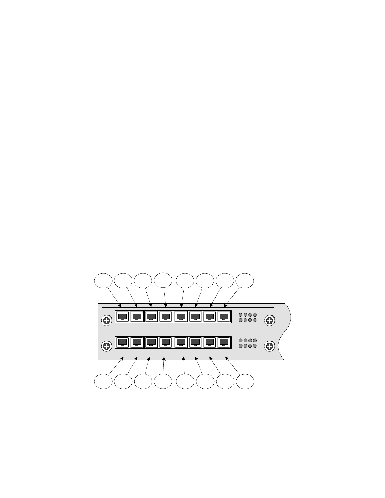
visible on the Max’s rear panel. Figure 1, below, shows the rear panel of a Max with two AVU
cards installed, each containing eight ports.
This section will explain how to remove the cards to conduct an inspection, and how to
differentiate between the port interface types. Again, this process is only required once,
before the Max’s LAN settings are configured.
1.5.1 Physical Port Numberi ng
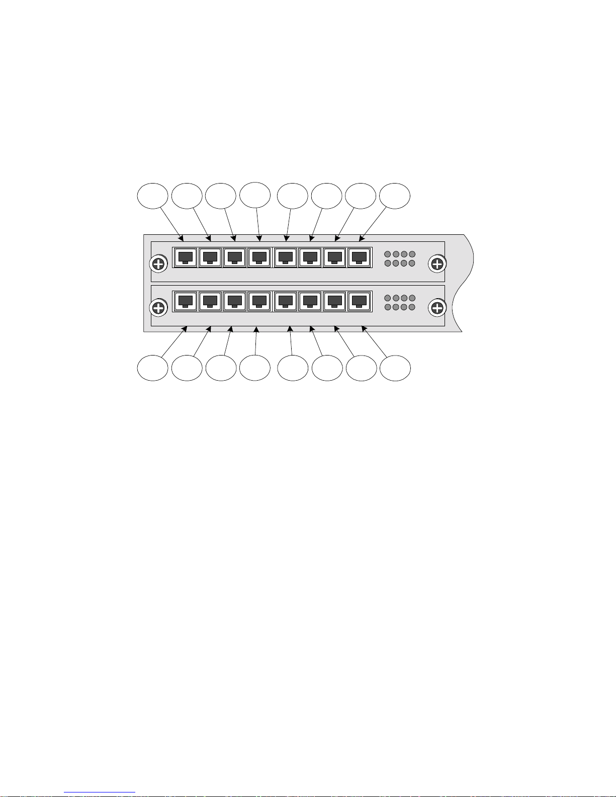
Figure 1 illustrates the physical port numbering on the Max’s rear panel for a unit with
16 ports installed. (Your unit may only have eight ports.) The Max Web Manager
references these numbers when identifying ports, setting up the Max’s features and
configuring Net2Phone calling accounts.
11
Port
3
4
Port
12
Port1Port
AVU
AVU
Port9Port
Port
2
1 2 3 4 5 6 7 8
1 2 3 4 5 6 7 8
Port
10
Figure 1 – Physical Port Numbers on the Max’s Rear Panel
As the illustration shows, the ports are numbered from upper left to lower right. In the
top row, the left-most port is port number 1 and the last is number 8. If you have 16
ports, the first port in the bottom row is port number 9 and the last, at the lower right,
is number 16.
Port5Port6Port7Port
8
1 2 3 4
5
6 7
1 2 3 4
5
6 7
Port13Port
14
Port15Port
16
8
8
Page 5
Page 11
Max 8/16 and T1/E1 User’s Guide Section 1 – Overview
Ports also have logical numbers, used by the Routing Table, which are different from
their physical numbers. (See Section 4.5, Routing Table Configuration.)
1.5.2 Identifying FXS and FXO Ports
If you do not know which ports on your unit are FXS or FXO, you can slide out the
cards and read the labels on the individual port cards. This section will explain that
process.
CAUTION: THE AVU BOARDS CAN BE DAMAGED BY STATIC DISCHARGE!
1. Before beginning, prepare a static-free surface on which to place the cards
when they are removed from the unit.
2. Employ an approved static-neutralizing wrist-strap and ground wire to avoid
damaging your unit with static dischar g e.
1.5.2.1 Removing an AVU Card
To remove an AVU card:
1. Turn off the power to the Max unit and unplug the power cord.
2. Place the unit on a desktop or other secure surface with the ports
facing you.
3. Turn the two thumbscrews on the top card counter-clockwise until
they are fully unscrewed (you feel springs pushing the screws out).
4. Grasp the screws between your thumbs and forefingers and, while
pushing against the cabinet with the free fingers, pull the card
straight out of its slot. It should come free with slight resistance.
DO NOT USE TOOLS TO PRY THE CARD FROM ITS SLOT!
DO NOT REMOVE INDIVIDUAL PORTS FROM THE AVU CARD!
1.5.2.2 Finding the Port Labels
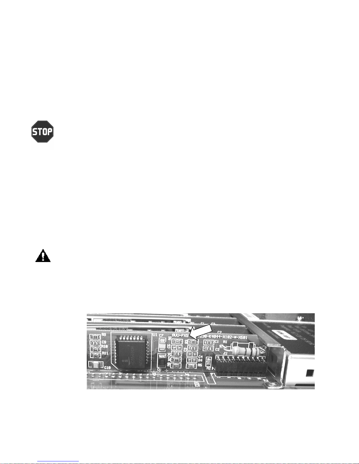
FXS port identification markings are visible on the right side of the port
card, as viewed with the AVU thumbscrews facing you. The label can
be seen at the arrow in Figure 2, below.
Figure 2 – FXS Ports
Page 6
Page 12
Max 8/16 and T1/E1 User’s Guide Section 1 – Overview
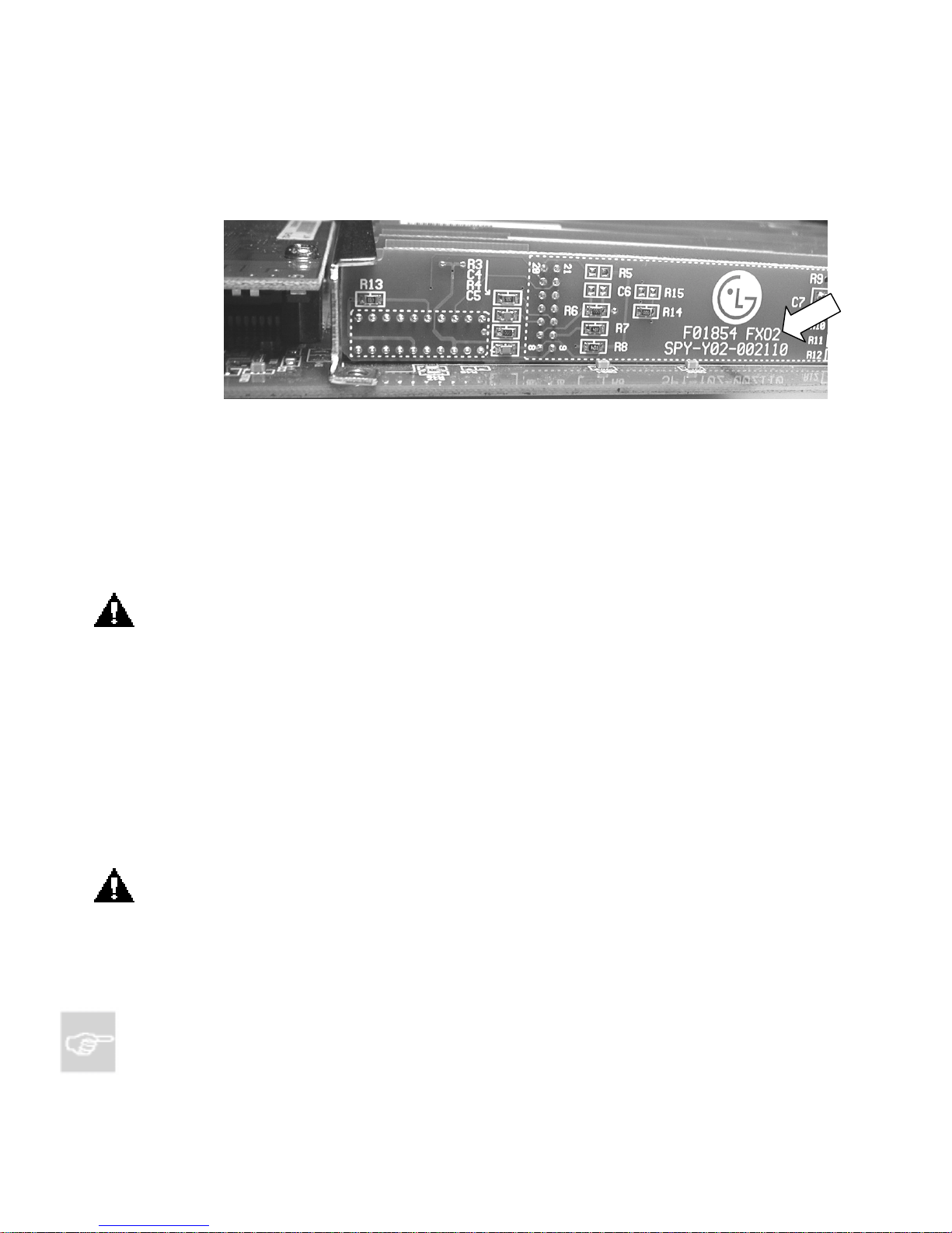
FXO port identification markings are visible on the left side of the port
card, as viewed with the AVU thumbscrews facing you. The label can
be seen at the arrow in Figure 3, below.
Figure 3 – FXS Ports
A Physical and Logical Port Number Table, Appendix D in this Guide, has
been provided for you to write down the positions of your FXS and FXO
ports so that they are available for future reference.
1.5.2.3 Replacing the AVU Card
To replace the AVU card in its slot:
1. Grasp the card securely by its two thumbscrews.
2. Slide the card into its socket. A slight resistance will be felt as the
card’s plug engages the receptacle inside the Max.
CAUTION: DO NOT FORCE THE CARD INTO ITS SLOT!
3. When the card’s bezel is flush with the rear panel of the Max, push
the two thumbscrews in and turn them clockwise to engage their
threads.
1.6 Installing the Max 8/16 or T1/E1
1. Install the unit in a well-ventilated area. If it is to be placed on a surface rather than in a
rack, be sure that all four rubber feet are in place to allow for proper air circulation. Do
not place objects in excess of 20 pounds on top of the unit.
PLEASE REFER TO THE NET2PHONE Max 8/16 AND T1/E1 HARDWARE INSTALLATION
GUIDE AND OBSERVE THE SAFETY PRECAUTIONS LISTED.
2. Connect an analog telephone to any one of the FXS ports. (Reminder: If you are not
sure which port or ports are FXS ports, refer to Section 1.5.2, Identifying FXS and
FXO Ports.)
NOTE: If no FXS ports are installed on the Max, initial LAN configuration is done via a PC
connected to the Max through its serial port, using the HyperTerminal terminal-emulator application
TM
(or equivalent), which is included wit h all Mic ros of t
Page 7
operating systems. (This is optional when
Page 13
Max 8/16 and T1/E1 User’s Guide Section 1 – Overview
FXS ports are present.) This procedure is explained in Section 2.1.1.1, Connecting to the Max
8/16 or T1/E1 Using HyperTerminal.
3. Connect the RJ-45 LAN port to a hub or switch.
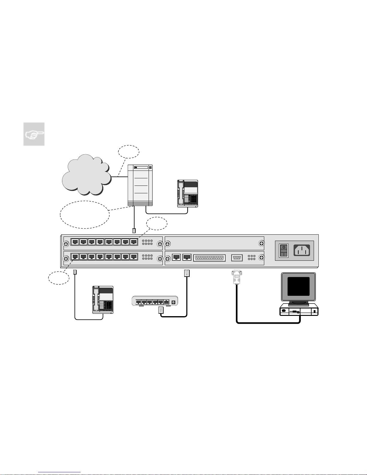
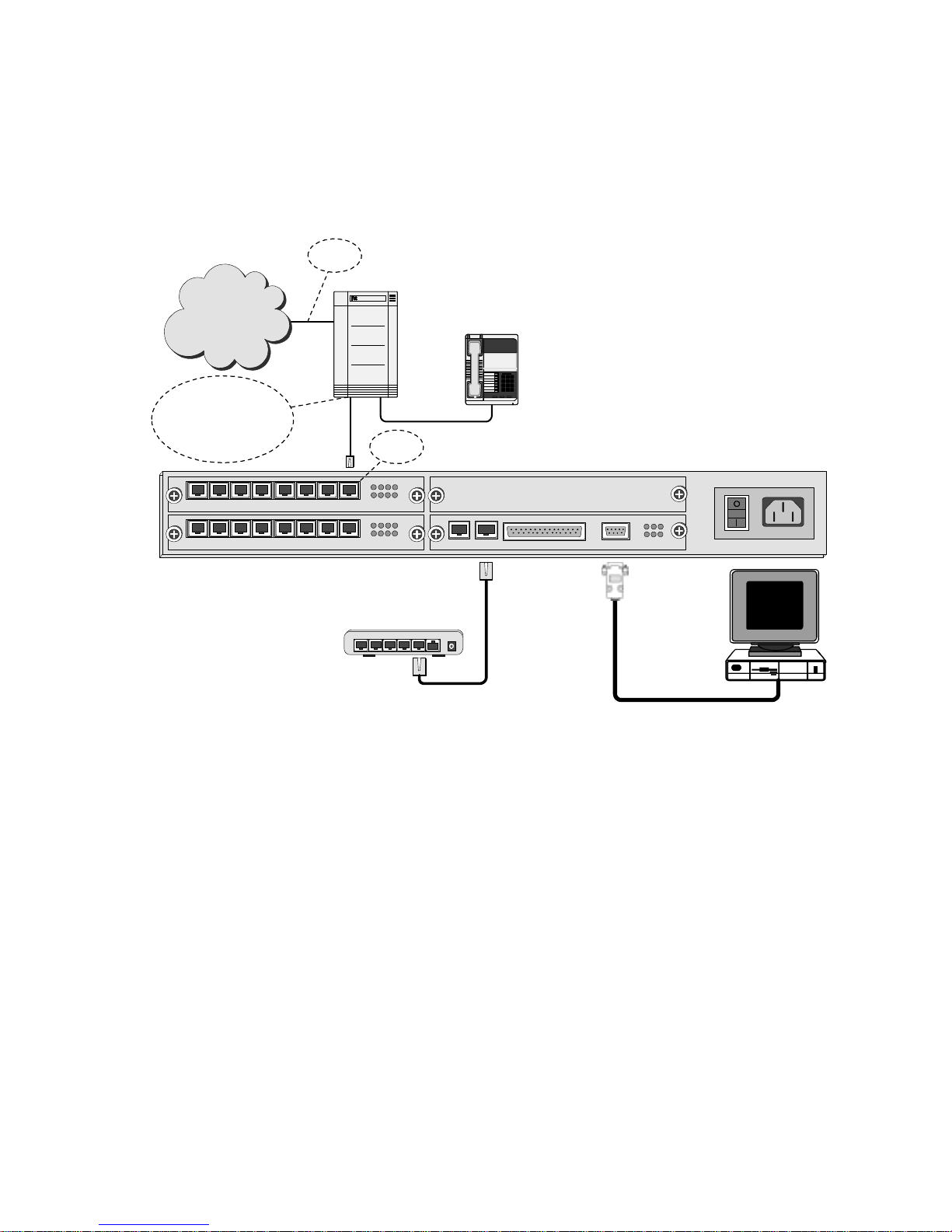
4. Connect your FXS and/or FXO ports to your PBX as per the illustrations in Figure 4 and
5, below.
1.6.1 Connecting the Max’s FXS Ports to a PBX
NOTE: FXS ports do not support IVR functionality.
PSTN
PBX
Connects to analog
trunk card, COIC
(COIB), or FXO card of
CO Line
PBX
Switch
FXS Port
PBX
Telephone
123
456
789
*
8#
COIC/COIB: Central Office Interface
Card or Board
PBX: Private Branch Excha nge
PSTN: Public Switched Telephone
Network
Trunk or CO Line: Line from Central
Office switch
1 2 3 4 5 6 7 8
AVU
1 2 3 4 5 6 7 8
AVU
1 2 3 4
6 7
5
1 2 3 4
6 7
5
8
BLK
8
SERIALLANE1/T1MPU
CONSOLE
OPR LTX ST X
SYN LRX SRX
PWR AC 110-240V
FXS Port
Analog
Telephone
123
456
789
*
Hub
or
Switch
432
5
8#
Uplink
1
Power
Figure 4 – Connecting the Max’s FXS Ports to a PBX
Page 8
Page 14
Max 8/16 and T1/E1 User’s Guide Section 1 – Overview
1.6.2 Connecting the Max’s FXO Ports to a PBX
CO Line
PBX: Private Branch Excha nge
PSTN: Public Switched Telephone
Network
PSTN
PBX
Switch
PBX
Telephone
SLIC/SLIB: Subscriber Line Interface
Card/Board
SLT: Single Line Terminal or
Telephone (analog
Connects to analog line
card, SLIC (SLIB or SLT)
card, FXS card, or station
card of PBX
1 2 3 4 5 6 7 8
AVU
1 2 3 4 5 6 7 8
AVU
1 2 3 4
5
6 7
1 2 3 4
5 6 7 8
FXO
Port
8
123
456
789
8#
*
BLK
SERIALLANE1/T1MPU
Trunk or CO Line: Line from Central
CONSOLE
OPR LTX STX
SYN LRX SRX
telephone)
Office switch
PWR AC 110-240V
Hub
5
Switch
432
or
1Uplink
Power
Figure 5 – Connecting the Max’s FXO Ports to a PBX
When you have finished connecting the Max’s FXS and FXO ports as illustrated
above, plug the unit into a power outlet and turn it on.
Your Net2Phone Max 8/16 and T1/E1 hardware setup is now complete. The next
step is to configure the unit to communicate with your LAN so that you can browse
the Max Web Manager.
Page 9
Page 15

Max 8/16 and T1/E1 User’s Guide Section 2 – Connecting the Max to a LAN
2. Connecting the Max 8/16 or T1/E1 to a LAN
Whether your LAN uses DHCP or static addressing, you can set the Max 8/16 or T1/E1 LAN
configuration in four ways:
via a touchtone keypad,
through a serial connection via the HyperTerminal terminal-emulator application, or
via the Web Management Tool (see Section 3, Logging Into the Max Web Manager, and
Section 4, Using the Max Web Manager).
This section explains how to set the Max 8/16 or T1/E1 LAN configuration using each method.
NOTE: On the Max 8/16 or T1/E1, LAN settings must be configured using a PC with a serial cable
connection using the Hyper T erminal terminal-emulator app lic at ion, which is included with all
TM
Microsoft
2.1 Connecting the Max 8/16 or T1/E1 to a DHCP LAN
operating systems.
Section 2.1 explains how to connect your Web browser to the Max 8/16 or T1/E1 if your LAN
uses DHCP addressing. If your LAN uses static IP addresses, skip to Section 2.2,
Connecting to a LAN with a Static IP Address.
The Max 8/16 or T1/E1 default configuration is for DHCP (Dynamic Host Configuration
Protocol). Therefore, if your LAN is using DHCP, the Max 8/16 or T1/E1’s IP address
parameters were configured automatically when you connected it to the LAN. In this case,
you only need to know the IP address that was assigned to the unit by the LAN before you
can browse the Max Web Manager, Max’s Web-based configuration system. If your LAN is
using DHCP, configuring the Max 8/16 or T1/E1 will entail the following steps:
1. Obtain the Max 8/16 or T1/E1’s current IP address.
2. Log in to the Max Web Manager.
3. Set the required configuration parameters in the Max Web Manager.
2.1.1 Obtaining the Max 8/ 16’s DHCP IP Address via a Telephone Keypad
The handiest way to query the Max 8/16’s current IP address is usually from a telephone
keypad (if an FXS port is present). To use this procedure you will need a standard analog
corded or cordless touch-tone telephone.
1. Get a pencil and paper to write down the IP address.
2. Connect an analog telephone to any FXS port on the Max 8/16 or T1/E1.
Page 10
Page 16
Max 8/16 and T1/E1 User’s Guide Section 2 – Connecting the Max to a LAN
3. Pick up the telephone handset and dial ***1 (***1 on the keypad).
The voice prompt responds, “Your address is…” and the IP address is
announced.
4. Write down the address and hang up the telephone. If you need to hear the
address again, hang up the telephone, then repeat step 3.
You are now ready to finish setting up the Max 8/16 or T1/E1 using the Max Web Manager.
Proceed to Section 3, Logging In to the Max Web Manager.
2.1.2 Connecting to the Max 8/16 or T1/E1 Throug h a Seri al Cable
Although the serial connection allows you to set many of the Max 8/16 parameters,
this section will only explain how to connect to the Max 8/16 or T1/E1 and obtain its
DHCP IP address. The remaining configuration tasks can then be completed more
easily via the Max Web Manager.
NOTE: If your Max 8/16 or T1/E1does not have any FXS ports installed, its LAN settings can
only be configured using this method.
2.1.1.1 Connecting to the Max 8/16 or T1/E1 Using HyperTerminal
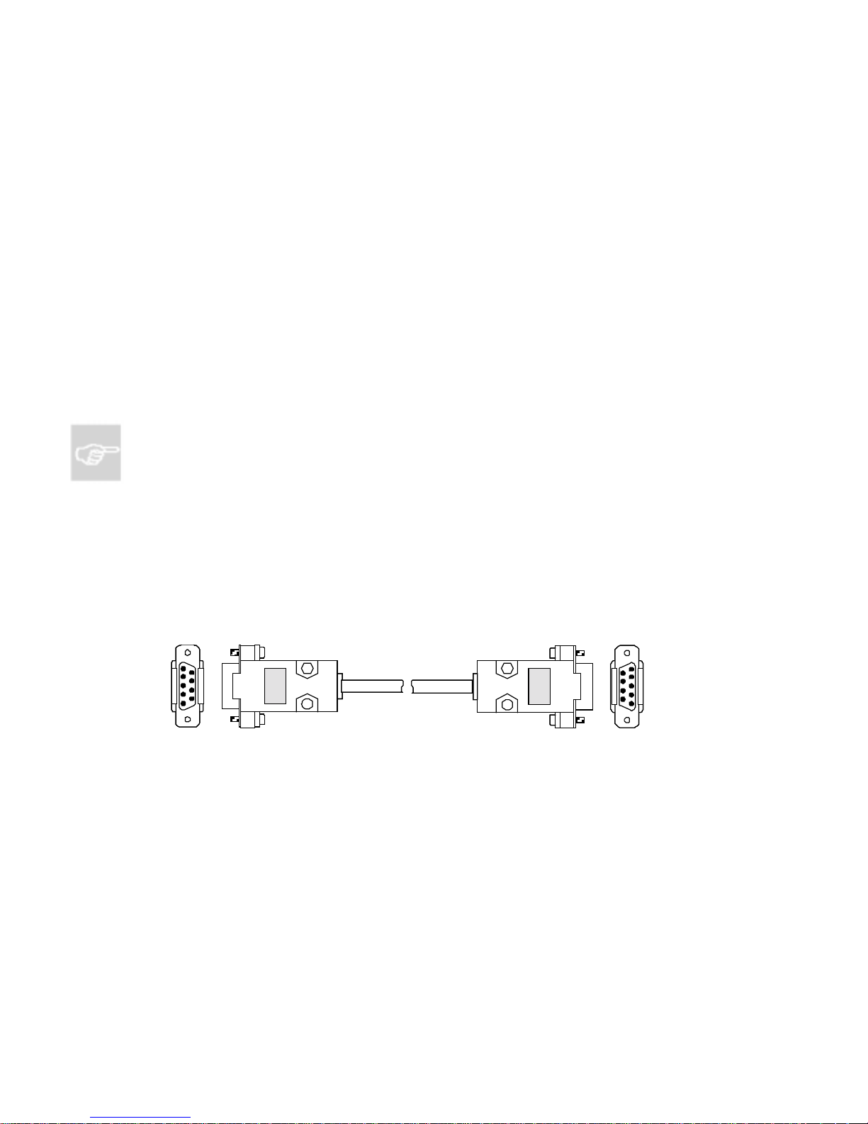
For this procedure, you will need a standard serial cable (D-sub 9-pin,
male-to-female, straight-through connection) and a PC or Mac running the
HyperTerminal terminal-emulator program (or an equivalent), which is
included in Microsoft operating systems. It is usually found in the Programs
menu, under Accessories.
Figure 6 – Console Cabl e for M ax 8/16 or T1/E1
1. With the power to the Max 8/16 or T1/E1 turned off, connect the cable
from the unit’s serial port to one of the PC’s serial ports. Note which of
the PC’s serial ports you are using.
2. Launch HyperTerminal and set up a new connection.
3. In the dialog box, specify the appropriate PC serial port, and set the
Page 11
serial communication parameters as follows:
Page 17

Max 8/16 and T1/E1 User’s Guide Section 2 – Connecting the Max to a LAN
Baud rate
Parity
Character size
Stop Bit
Flow Control
19200
None
8
1
None
4. Power-on the Max 8/16 or T1/E1, then press the Enter key on your
PC.
The boot messages are displayed, followed by the command prompt
n2p:>.
NOTE: n2p is the default system name with which the unit is shipped. This can be
replaced by a system name you select, such as
MY_Max:>. To change the system name,
see Section 4.11, System Information and Commands.
5. Press the Enter key.
The Login: prompt is displayed.
6. Three default user IDs are provided:
• root
• manager
• sysadm
Type one of these user IDs at the Login: prompt, followed by the
Enter key. For example, type
root, followed by the Enter key.
The Password: prompt appears.
7. At the Password: prompt, type the default password,
n2p, followed
by the Enter key.
The command line prompt n2p:> appears. You are now logged in.
NOTES:
Max 8/16 or T1/E1 provides three fixed user (or manager) names.
You can change any manager’s password, but managers cannot be created, deleted,
or renamed.
Manager names and passwords are case sensitive.
2.1.1.2 Obtaining the Max 8/16 or T1/E1’s DHCP IP address via HyperTerminal
If your LAN uses static addresses, refer to Section 2.2.1, Entering Static
IP Addresses via HyperTerminal (Max 8/16 and T1/E1).
1. Make a serial connection from your computer to the Max 8/16 or T1/E1.
Page 12
Page 18

Max 8/16 and T1/E1 User’s Guide Section 2 – Connecting the Max to a LAN
2. After logging in to the Max 8/16 or T1/E1, type /config/ip at the
command prompt.
The active directory changes to
becomes
n2p:/config/ip>.
/config/ip and the prompt
3. Type
show and then press the Enter key.
The Max 8/16 or T1/E1’s IP address and netmask are listed on the
screen. Write them down and keep them for future reference.
If your LAN uses DHCP, you are now ready to finish setting up the Max
8/16 or T1/E1 using the Max Web Manager. Proceed to Section 3,
Logging In to the Max Web Manager.
2.2 Connecting to a LAN with Static IP Addresses
This section explains how to connect your Web browser to the Max 8/16 or T1/E1 if your LAN
uses static IP addresses, using either a telephone keypad or serial connection. The process
will entai l the following steps:
1. Disable DHCP in the Max 8/16 or T1/E1.
2. Enter a static IP address.
3. Enter a netmask address.
4. Reset the unit.
5. Log in to the Max Web Manager.
6. Set the required configuration parameters in the Max Web Manager.
2.2.1 Entering Stati c I P ad dresses from a Telephone Ke ypad
If your LAN uses static IP addresses, the most practical way to set up the Max 8/16 or T1/E1
is to enter an IP address and netmask from a telephone keypad. You can then finish setting
up the unit while browsing the Max Web Manager.
2.2.1.1 Disabling DHCP from a Telephone Keypad
Since the Max 8/16 and T1/E1 are shipped with DHCP enabled, you need
to disable DHCP to use static IP addresses.
To disable DHCP:
1. Connect an analog telephone to any RJ-11 port on the Max 8/16.
2. Lift the handset and dial
***5 (the disable DHCP parameter code).
The voice prompt announces, “DHCP is disabled now. Please press
pound”.
Page 13
Page 19

Max 8/16 and T1/E1 User’s Guide Section 2 – Connecting the Max to a LAN
3. Press the pound key (#).
4. Hang up the telephone.
DHCP is now disabled.
2.2.1.2 Entering an IP Address from a Telephone Keypad
Ask your LAN administrator for the IP address that will be assigned, the
LAN’s netmask address, domain name, and any other IP parameters that
can be provided.
To enter the IP address:
1. Lift the telephone handset and dial
***2 (the IP address parameter
code).
The voice prompt responds, “Please enter your IP address.”
2. Dial the numbers for the IP address you wish to enter on the
telephone keypad. Use the star key (*) to replace the periods in the
address and end with the pound key (#).
For example, if you want to enter the IP address 192.168.172.19, you
would enter
192*168*172*19# from your telephone keypad.
The voice prompt responds, “Your IP address is…” and repeats the
address you entered.
3. If the new address is correct, simply hang up the telephone. If the
new address is incorrect, hang up the telephone and repeat from
step 1, above.
4. Reset the Max 8/16 or T1/E1 to activate the changes. To do this,
power-off the unit, wait 10 seconds, and turn it on again.
DHCP is now disabled.
You are now ready to finish setting up the Net2Phone Max 8/16 using the
Max Web Manager. Proceed to Section 3, Logging In to the Max Web
Manager.
2.2.1.3 Entering a Netmask Address from a Telephone Keypad
To enter a netmask address:
1. Lift the handset and dial
2. Proceed as in step 2, above, entering the desired netmask address
Page 14
***3 (the netmask parameter code).
The voice prompt responds, “Please enter your netmask.”
from the telephone keypad.
Page 20

Max 8/16 and T1/E1 User’s Guide Section 2 – Connecting the Max to a LAN
The voice prompt responds, “Your netmask address is…” and
repeats the address you entered.
3. Proceed as in step 3, above.
4. Reset the Max 8/16 or T1/E1 as directed in Step 4 in Section 2.2.1.2,
above.
The new netmask address is now in effect.
If you are using static IP addresses, you are now ready to finish setting up
the Max 8/16 or T1/E1 using the Max Web Manager. Proceed to Section 3,
Logging In to the Max Web Manager.
2.2.1.4 Re-enabling DHCP from a telephone keypad
If you need to re-enable DHCP in the Max 8/16 or T1/E1, proceed as
follows:
1. Lift the handset and dial
***4 (the enable DHCP parameter code).
The voice prompt announces, “DHCP is enabled now. Please press
pound.”
2. Press the pound key (#).
DHCP is now enabled.
The telephone keypad configuration parameter codes are as follows:
Read IP address
***1 DHCP disable ***5
Assign static IP address ***2 DHCP enable ***4
Assign netmask ***3
2.3 Entering Static IP Addresses via HyperTerminal
Although many of the Net2Phone Max 8/16’s IP parameters can be set manually
through the serial connection, if desired, this section will only show you how to set the
IP address and netmask parameters. The procedure is as follows.
NOTE: If your unit has no FXS ports, its LAN settings can be configured only by this method.
Page 15
Page 21

Max 8/16 and T1/E1 User’s Guide Section 2 – Connecting the Max to a LAN
2.3.1 Turning DHCP On (or Off) from Hy perTerminal
The Max 8/16 or T1/E1’s default DHCP setting is DCHP enabled. Before you can
enter a static IP address, you must first disable DHCP. (The same procedure is
used to re-enable it, if necessary.)
1. Make a serial connection from your computer to Max 8/16 or T1/E1.
2. After logging in to the Max 8/16 or T1/E1, type
prompt.
The active directory changes to
n2p:/netutil>.
3. Type
4. Type
dhset disable followed by the Enter key.
dhcpd disable followed by the Enter key.
The Max 8/16 or T1/E1’s DHCP feature is now disabled.
5. Type
6. At the
/SYS to move to the system directory.
n2p:/system> prompt, type reset.
7. At the confirmation line, type
2.3.2 Entering an IP Address
To connect to the Max 8/16 or T1/E1 Web Manager, you will need to enter at least an
IP address and netmask. From the DOS prompt, type:
IP configuration directory.
1. Type change to activate the interactive IP setting menu.
2. Type the number of the parameter you want to enter or change.
/netutil at the command
/netutil and the prompt becomes
y to proceed.
/CONFIG/IP to move to the
3. At the
Enter <parameter>: prompt, enter the desired value.
Example:
a. Enter 1 at the menu prompt to change the IP Address.
b. At the prompt, enter the IP address you wish to assign.
4. When you finish making changes, reset the Max 8/16 or T1/E1 to activate the
changes.
You may either:
Type
OR
Power-off the unit, wait 10 seconds, and turn it on again.
Page 16
/system/reset at the command line
Page 22
Max 8/16 and T1/E1 User’s Guide Section 2 – Connecting the Max to a LAN
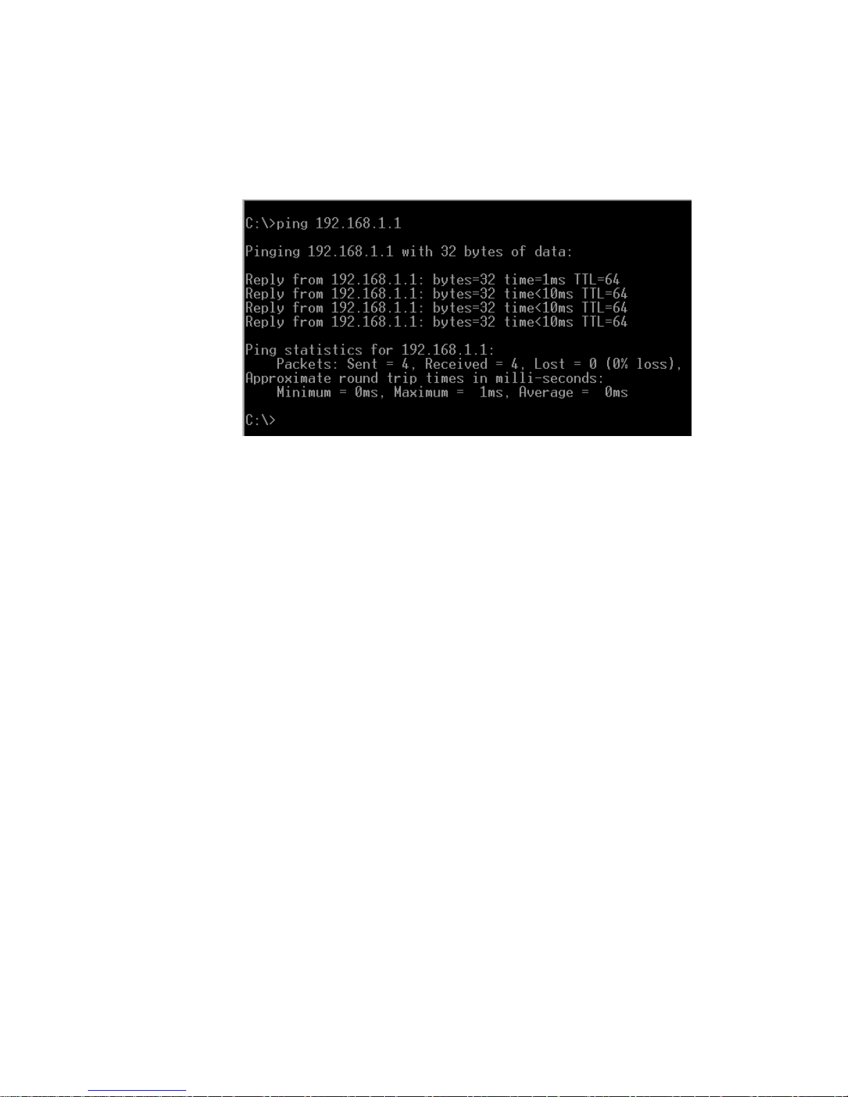
5. (Optional) Ping the Max 8/16 or T1/E1 from a PC, as illustrated below, using
the new IP address, to confirm that the correct parameters have been entered
and stored successfully.
Figure 7 – Pinging the M ax Unit
The new IP address and netmask are now in effect. If you are using static IP
addresses, you are now ready to finish setting up the Max 8/16 or T1/E1 using
the Max Web Manager. Proceed to Section 3, Logging In to the Max Web
Manager.
Page 17
Page 23
Max 8/16 and T1/E1 User’s Guide Section 3 – Logging Into the Max Web Manager
3. Logging In to the Max Web Manager
Before you can log in to the Max Web Manager, you need to know the Max 8/16 or T1/E1’s current
IP address. Refer to the procedures in Section 2 to obtain its IP address via serial connection.
Reminder: If you want to query the unit through a serial cable, see Section 2.1.1, Connecting
to the Max 8/16 or T1/E1 Through a Serial Cable.
Once you know the Max 8/16 or T1/E1’s IP address, you are ready to log in to the unit through a
Web browser as follows:
1. Open a new browser window and enter the Max 8/16 or T1/E1 ’s IP address in the address
box.
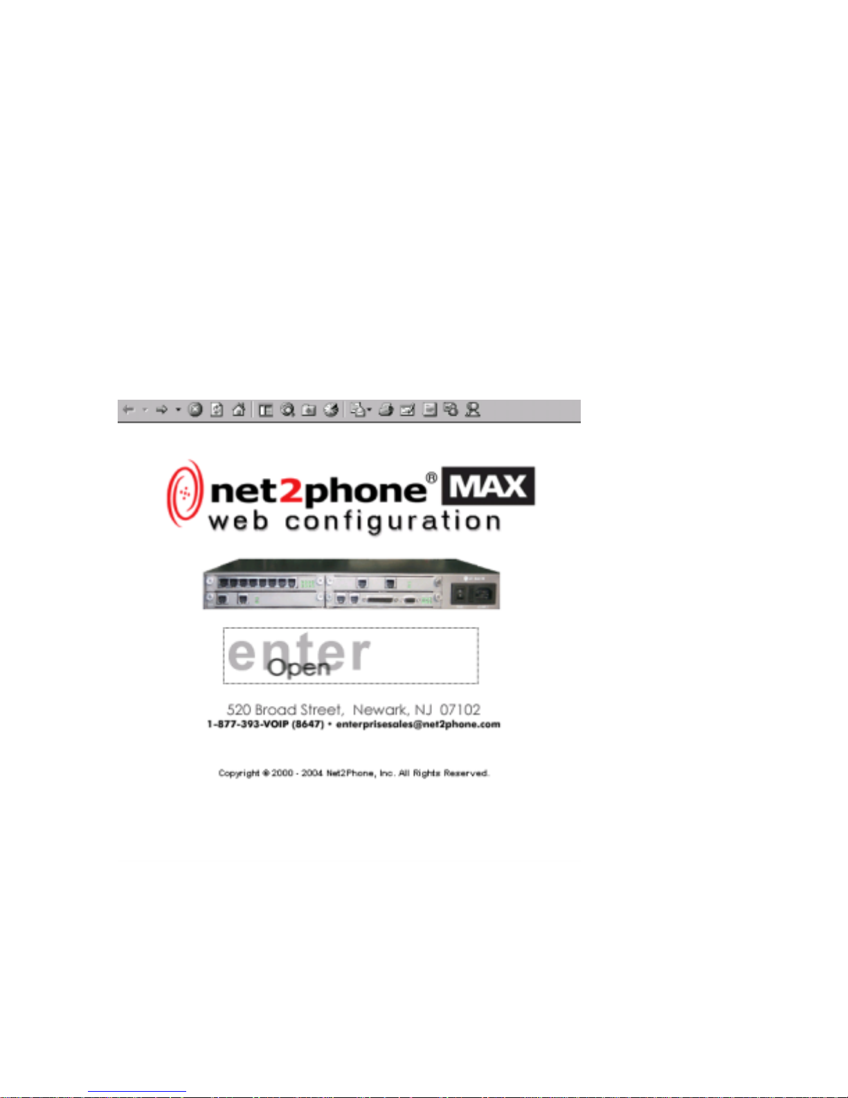
The Max Web Manager Door page appears.
Figure 8 – Max Web Manag er Door Pag e
Page 18
Page 24
Max 8/16 and T1/E1 User’s Guide Section 3 – Logging Into the Max Web Manager
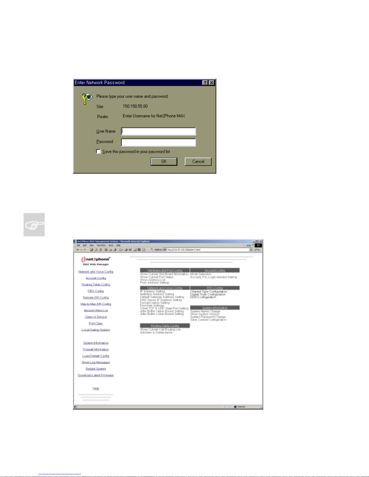
2. Click the ‘enter - Open‘ area.
The Enter Network Password dialog box appears.
Figure 9 – Network Password Dialog Box
3. Enter your user name and password and click the OK button.
You are now logged in. The Max Web Manager Site Map page app ear s.
NOTE: The default user name is root and the default password is n2p. If you changed your
password and have forgotten it, please email [email protected].
Figure 10 – Max Web M anager Site M ap
Page 19
Page 25
Max 8/16 and T1/E1 User’s Guide Section 4 – Using the Max Web Manager
4. Using the Max Web Manager
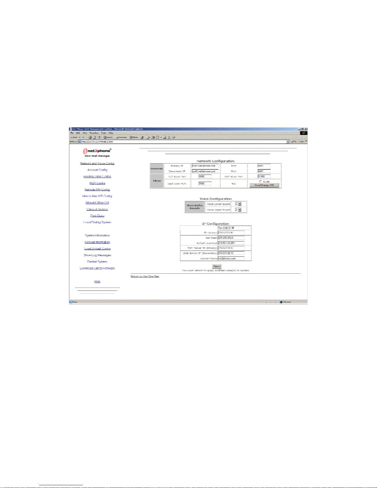
To access a particular configuration page, click the corresponding link on the Site Map page. For
example, click the Network and Voice Config link on the Site Map to access the Network and
Voice Configuration page, illustrated below.
4.1 Network and Voice Configu rati on [NIC feature added]
Figure 11 – Network and Voic e Configurat ion Page
Any of the parameters on the Network and Voice Configuration page can be modified by
simply entering the desired values into the respective boxes.
The IP Configuration table displays all the Max 8/16 or T1/E1 ’s IP-related parameters.
The Voice Configuration table displays the Jitter Buffer Bounds, which are used to control the
Quality of Service (QoS). The upper and lower bounds can be changed; larger bounds
produce less packet loss, while smaller bounds produce more packet loss. However, packet
delay increases with the bounds size. The default values in this table should not normally be
changed.
Page 20
Page 26

Max 8/16 and T1/E1 User’s Guide Section 4 – Using the Max Web Manager
DHCP users: If your LAN is using DHCP addresses, you do not have to configure this page.
You may proceed directly to Section 4.3, Configuring Accounts, below.
Static address users: Your IP address and netmask are already present in the IP
Configuration table (you entered them previously). Now you need to enter the additional IP
parameter information you obtained from your LAN administrator:
Default Gateway
DNS Server IP (Primary)
DNS Server IP (Secondary)
Domain Name (if applicable)
NOTE: If a default gateway address or a DNS server address is not used, the value 0.0.0.0 must be
entered into their respective boxes. If the boxes are left blank, the modified configuration settings
will not be saved.
The Network Configuration table displays the doorman IP addresses and ports, and the
TCP/UDP start ports.
The Port Numbers parameters must be changed to permit access when a LAN’s firewall
permits only pre-assigned TCP/UDP port numbers to be used.
The NIC code entry has been added to the Network Configuration table for controlling the
remote access to the Max 8/16 or T1/E1 device. Only the user with the account number
belonging to the designated NIC code can access the device. The NIC code can be obtained
from Net2Phone. To protect users, NIC configuration is password protected and can only be
changed by reseller support at Net2Phone.
Reminder: Configuration changes you make in the Max 8/16 or T1/E1 are not applied until you
reset the unit. To do this, you may either:
Go to the [email protected] System page (see Section 4.12.3, Restart
System, below) and click Restart;
Type
/system/reset at the command prompt; or
Power-off the unit, wait 10 seconds, and turn it on again.
Page 21
Page 27

Max 8/16 and T1/E1 User’s Guide Section 4 – Using the Max Web Manager
4.2 Configuring Firewalls
If your connection to the Internet utilizes a firewall, several ports will have to be opened to
allow your Max 8/16 or T1/E1 to make and receive calls to other Net2Phone devices.
UDP Port 6801 must be opened. The following port types/ranges must also be opened (the
numbers displayed are the default start points for each):
1. UDP Port (OPAL) 7000
2. TCP Port 4000
3. UDP Port 21000
The table below explains the procedure for opening firewall ports for your Max 8/16 or T1/E1.
This example illustrates the UDP Port (OPAL) assignments (with a default start point of 7000)
for an 8-port Max 8/16 or T1/E1.
Max Port # Firewall
Port Type
Firewall Port
Numbers
1 UDP Port (OPAL) 7000 - 7001
2 UDP Port (OPAL) 7002 - 7003
3 UDP Port (OPAL) 7004 - 7005
4 UDP Port (OPAL) 7006 - 7007
5 UDP Port (OPAL) 7008 - 7009
6 UDP Port (OPAL) 7010 - 7011
7 UDP Port (OPAL) 7012 - 7013
8 UDP Port (OPAL) 7014 - 7015
In this example, the range to be opened is 7000 to 7015. The range is determined by the
following formula:
Max Default Start Port + (Number of Max Ports * 2) – 1
or in this example:
7000 + (8*2) – 1 = 7015
The table shows the firewall port assignments based on the default start port. If the Max
gateway default start ports noted above are in conflict with your corporate firewall settings,
you may assign port numbers in the range of 4000 to 65000 by applying the same principle
illustrated in the table.
Page 22
Page 28

Max 8/16 and T1/E1 User’s Guide Section 4 – Using the Max Web Manager
The TCP Port and UDP Port start parameters in the Network Configuration table must match
the open firewall ports.
NOTE: If you have more than one Max behind the same firewall, you must repeat the process for
each unit, opening a different UDP PORT and TCP PORT for each.
NOTE: The Max 8/16 and T1/E1 gateway will not work behind a proxy server.
In Max-to-Max calling (when you call a Max unit from another Max), if either Max is connected
to a LAN that employs a firewall, you will need to configure settings on both the Max and the
firewall before Max-to-Max calls can be placed. This section will explain how to make the
necessary adjustments.
1. On the Firewall:
a. Open UDP Port 6801.
b. Open an additional UDP Port in the range of 21000-65535.
c. Open a TCP Port in the range of 4000 – 4015 for 8 ports and 4000 – 4031 for 16
ports. This must not be the same number port you opened in the previous step.
(The maximum number in the range is determined by the following formula:
Maximum = 4000 + (number of ports * 2) – 1.)
2. In the Network Configuration Table on Max’s Network and Voice Configuration page:
After opening the appropriate UDP Port and TCP Port on the firewall, you must specify
these open ports on the Max device(s):
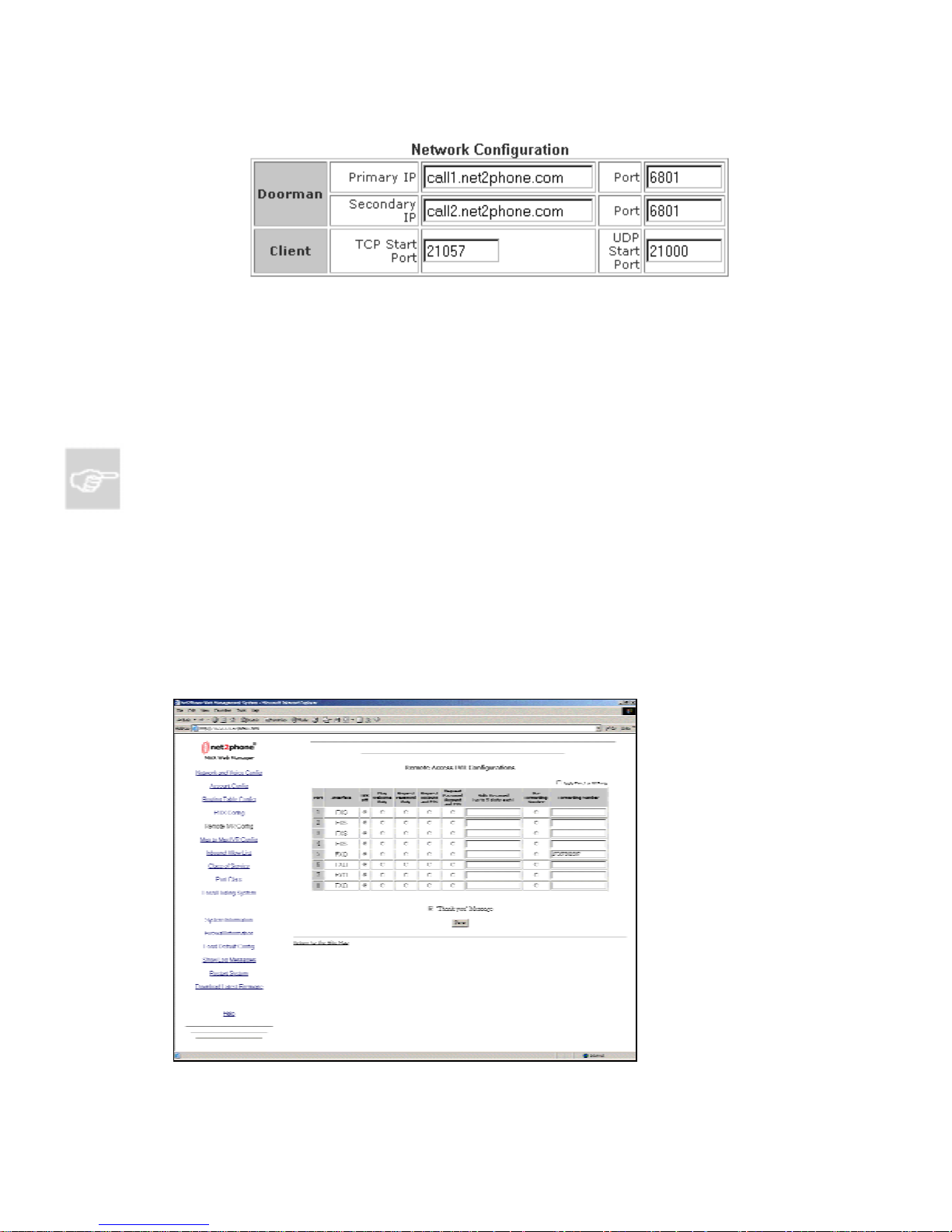
a. Change the TCP Start Port to the port you opened in step 1-c above. For
example, if you opened TCP Port 21057 in step 1-c, enter
21057 for the TCP
Start Port as shown in Figure 12 – Network Configuration Table, below,
illustrating the Network Configuration Table on the Network and Voice
Configuration page.
b. Change the UDP Start Port to the port you opened in step 1-b above. For
example, if you opened UDP Port 21000 in step 1-b, enter
21000 for the UDP
Start Port as illustrated in Figure 12 – Network Configuration Table, below.
Page 23
Page 29
Max 8/16 and T1/E1 User’s Guide Section 4 – Using the Max Web Manager
Figure 12 – Network Configuration Table
3. Save your settings and restart the Max 8/16 or T1/E1:
After you have made the desired changes, click the Save button at the bottom of the
page to save the new settings, then restart the unit.
The new settings should now be in effect.
NOTE: Some firewalls require the opened port to be forwarded to the Max 8/16 or T1/E1’s IP
address. Consult your LAN administrator to determine if this is the case with your firewall.
4.3 Port Identification with the Web Manager
The Web Manager makes it easy to determine which of the ports on the Max 8/16 are FXO
and which are FXS. The Configuration Manager allows you to do this by referring to the
Remote Access IVR Configuration Table.
To go to the Remote IVR Access Configuration Table, click the Remote IVR Config link on
the Site Map page.
Figure 13 – Remote Access IVR Configuration Page
Page 24
Page 30
Max 8/16 and T1/E1 User’s Guide Section 4 – Using the Max Web Manager
The Port and Interface columns of the Remote Access IVR Configuration Table show clearly
which interface is used by each port, using the physical port numbering scheme illustrated
below, which was discussed previously in Section 1. This numbering scheme is also used by
the Max-to-Max Configuration Table, and the Account Configuration Table, which are
discussed later in this Guide.
Port1Port
2
Port
Port
3
4
Port5Port6Port7Port
8
1 2 3 4 5 6 7 8
AVU
1 2 3 4
5
6 7
1 2 3 4
8
5
6 7
1 2 3 4 5 6 7 8
AVU
8
Port9Port
10
Figure 14 – Physical Port Numbers on the Max’s Rear Panel
Port
11
Port
12
Port13Port
14
Port15Port
16
It is also possible to slide out an AVU card and read the label on individual port cards (see
Section 1.5.2, Identifying FXS and FXO Ports), but this should seldom be necessary once
your LAN configuration is set.
A different port numbering scheme, called logical port numbering, is used by the Rout ing
Table. Logical port numbering is discussed in Section 4.5.1, Logical Port Numbering, of
this Guide.
Page 25
Page 31
Max 8/16 and T1/E1 User’s Guide Section 4 – Using the Max Web Manager
4.4 Account Configuration with Multiple DID/Account Balance Announcement
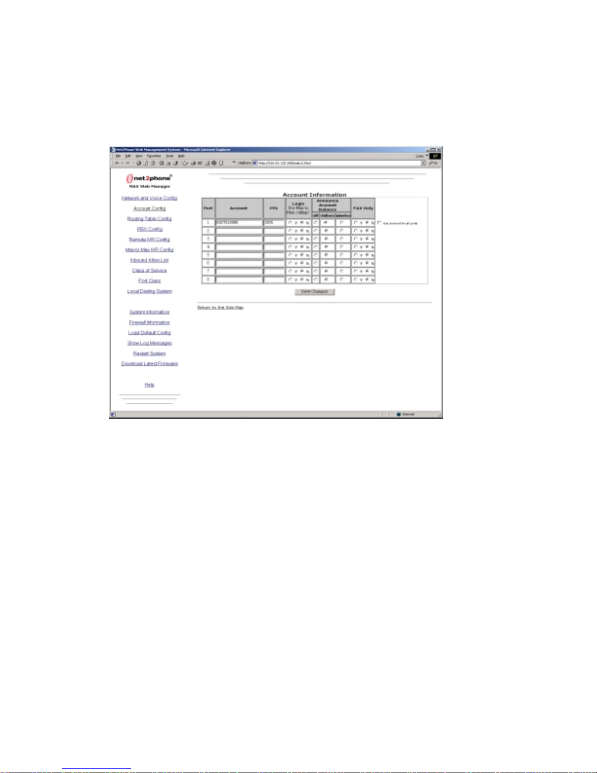
Click the Account Config link to access the Account Information page, illustrated below.
Figure 15 – Account Informati on Page
The Max 8/16 or T1/E1 allows accounts to be managed in either of two ways:
Single Account Management - All of the ports on the Max 8/16 or T1/E1 can operate
from a single account number and PIN, or
Multiple Account Management - You can use a different account and PIN for each
port.
The multiple DID feature enables Max 8/16 or T1/E1 to receive multiple incoming calls on a
single DID account. Simply enter a single DID account, and click the Use account for all
ports button. When you click the Announce Account Balance box in the Account
Information screen, you can now check the remaining balance on your Net2Phone account.
Page 26
Page 32

Max 8/16 and T1/E1 User’s Guide Section 4 – Using the Max Web Manager
4.4.1 Single Account Management
For single account management:
1. In the box for Port #1 in the Account column, enter a Net2Phone account
number.
2. In the PIN field, enter the Personal Identification Number for that account.
3. Check the Use account for all ports checkbox.
4. If you wish to be able to receive incoming Max-to-Max calls on a given port,
select the Y radio button in its Login column.
5. After the desired changes have been entered, click the Save button at the
bottom of the page to save them.
NOTES:
To receive Max-to-Max calls when multiple ports are sharing a single account, only one of
the ports sharing the account may have the Y selected.
Only one call at a time can be made using any given account number.
If a Net2Phone account number is entered for an FXO port in the Account Configuration
Table, the account entered acts as a “default” account for the port. Charges incurred by
callers through that port automatically accrue to this account.
Whenever a selection in the Login column is modified, the Max must be restarted before
the change will take effec t.
4.4.2 Multiple Acco unt Management
For multiple account management:
1. For each port that is connected to a telephone or PBX/KPS, enter the account
number and PIN you intend to use with that port.
2. Make sure that Use account for all ports is NOT checked.
6. Click the Restart System link on the Site Map page to reboot the system.
3. After the desired changes have been entered, click the Save button to save
them.
4. Click the Restart System link on the Site Map page to reboot the system.
4.4.3 The Login Button
The Yes radio buttons in the Login column are used to enable a port to receive
incoming Max-to-Max calls.
Page 27
Page 33
Max 8/16 and T1/E1 User’s Guide Section 4 – Using the Max Web Manager
4.5 IVR (Interactive Voice Respon se) Configuration
The remote access IVR and Max-to-Max IVR supports multiple passwords. Up to 10 different
passwords can be entered, separated by comma ( , ).
Remote access IVR is supported for FXS/FXO/T1/E1 ports, and Max-to-Max IVR is
supported for FXO/T1/E1 ports. For FXS/T1/E1 IVR, user must add the IVR access number
to the routing table for IVR access. The IVR access number can be generated by adding an
entry in the routing table with the IVR interface type.
4.5.1 The Remote Access IVR Configuration Table
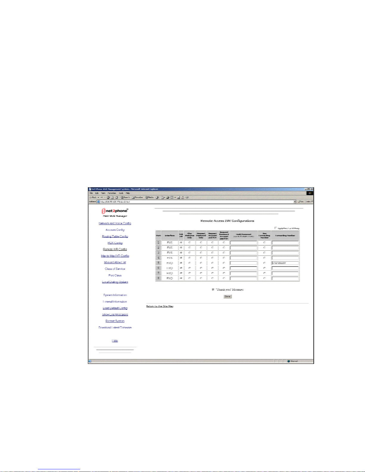
Click the Remote IVR Config link on the Site Map page to view the Remote Access
IVR Configuration Table, illustrated below.
Figure 16 – Remote Access IV R Configur ation Ta ble
Multiple passwords are supported for more flexibility.
A “Thank you” message can be enabled or disabled by using the check box.
Page 28
Page 34

Max 8/16 and T1/E1 User’s Guide Section 4 – Using the Max Web Manager
The Remote Access IVR function permits system managers to select the
announcement that will greet callers to an FXO port, as well as the security, call
forwarding, or other options that may be applied to the port.
The Remote Access IVR Configuration Table (Figure 16) allows you to configure
these options to suit your requirements.
To configure the Remote IVR Configuration Table, proceed as follows:
1. Make sure the FXO port you are configuring is connected to the analog line
card of a PBX unit.
2. Be certain that a PBX or PSTN telephone number has been assigned to the
port.
3. Select one of the following six modes for the port (only one mode at a time may
be selected):
IVR Off – When IVR Off is selected for a port, callers to the port get an
immediate VoIP dial tone and can make VoIP calls without restriction.
Play Welcome Only – When this option is selected, callers to the port hear
a welcome message, “Welcome to Net2Phone. Please enter the number
you wish to call.” Callers can then make VoIP calls without restriction.
Request Password Only – This option prevents unauthorized access to
the FXO port on which it is set. Callers are asked to enter a password
through the telephone keypad before access to VoIP calling is permitted.
Callers can then make VoIP calls without restriction.
To configure this option, you must create a password (in the port’s
Password column) which may consist of up to 5 (numeric only) characters.
Request Account and PIN – This feature requires the caller to enter a
Net2Phone account number and PIN before VoIP calling is enabled. If the
caller then incurs charges whi le using the Net2 Ph one Max , the y will acc r ue
to the caller’s account.
See IMPORTANT, below.
Request Password, Account and PIN – This option combines the two
functions described above.
Use Forwarding Number – Select this IVR option for a port if you wish to
have incoming calls to that port forwarded to a specified number
automatically, without notice to the caller. Any PSTN telephone number, or
a Net2Phone account number preceded by *72, may be entered in the
Forwarding Number column.
If a PSTN number is e nter e d, it must include any requ i r ed preliminary digits,
such as a 1 for long-distance calling.
Page 29
Page 35
Max 8/16 and T1/E1 User’s Guide Section 4 – Using the Max Web Manager
IMPORTANT: If a Net2Phone account number is entered for an FXO port in the Account
Configuration Table (see Configuring Accounts, Section 4.3), the account entered acts as a
“default” account for the port. Charges incurred by callers through that port automatically accrue to
this account.
If Request Account and PIN or Request Password Account and PIN is then selected, and a
caller enters an incorrect or invalid account number, the port will substitute this “default” account
number for the invalid one and the call will proceed using the default account.
Unless this arrangement suits your needs, you must clear any account number that may have been
entered for an FXO port in the Account Configuration Table when Request Account and PIN or
Request Password Account and PIN are selected.
2.
PBX hands
call off to first
available
port, in this
case, port
3504.
MAX 8/16
sends call
Network via
Ext. 3501
Ext. 3502
Ext. 3503
Ext. 3504
4.
to N2P
Internet.
LAN
Internet
Net2Phone
Network
5.
N2P
Network
sends call
to PSTN.
PSTN
1.
Caller dials
Ext. 4000, a
hunt group
with 4 FXO
ports.
Extension
PBX
Analog Line
Card
123
456
789
8#
*
MAX 8/16
FXO Ports
PBX
Switch
Port 3504's IV R resp ond s
(depending on opti ons
"Welcome to Net2Phone.
Please enter your password."
(Caller enters a password.)
IVR continues: "Please enter
the number you wish to call."
(Caller enters tel epho ne
number 12125556791.)
3.
selected):
6.
Telephone
connected to line
212 555-6791
rings.
123
456
789
*
8#
Figure 17 – Call Flow Through a M ax 8/16 or T1/E1’s FXO Po rt
Page 30
Page 36
Max 8/16 and T1/E1 User’s Guide Section 4 – Using the Max Web Manager
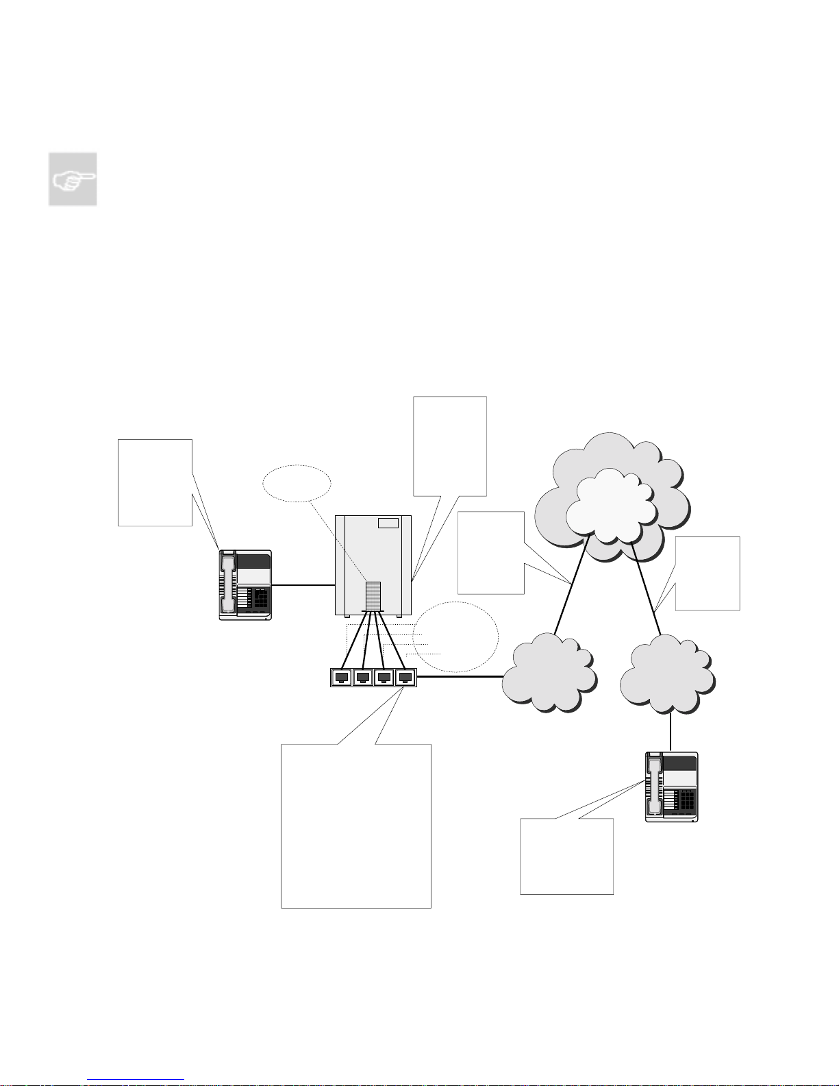
Figure 17, above, illustrates the call-flow of a telephone call placed through a Max 8/16’s
FXO port. In this scenario, four FXO ports are connected to the PBX in a hunt group set
up at extension 4000.
4.5.2 The Max-to-Max IV R C onfiguration Table
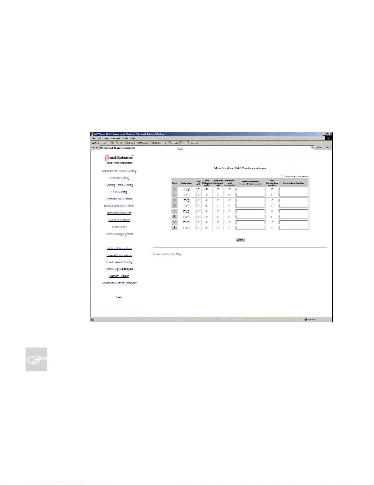
Click the Max to Max IVR Config link on the Site Map page to view the Max-to-Max
IVR Configuration Table, illustrated below.
Figure 18 -- Max-to-Max IVR C onfigur ation Ta ble
NOTES:
If the LAN to which either Max is connected employs a firewall, you need to configure settings
on both the Max unit and the firewall before you can place Max-to-Max calls. For information
Port about configuring a firewall, refer to Section 4.2, Configuring Firewalls, in this Guide.
In Max-to-Max calling, the receiving port’s Account Information table settings must be
configured to permit it to receive calls. For details, refer to Section 4.4.2.2, Recei v in g Max-to -
Max Calls in this Guide.
Page 31
Page 37

Max 8/16 and T1/E1 User’s Guide Section 4 – Using the Max Web Manager
4.5.2.1 Configuring Max-to-Max Calling
Callers may access a port on a remote Max 8/16 from another Max device
(Max-to-Max) by dialing *72 followed by the receiving port’s virtual
number, which is the first ten digits of its account number.
If the receiving port is an FXS port, the telephone connected to the port
will ring.
If the receiving port is an FXO port, it permits callers to use its PBX as
though they were on a local PBX telephone extension, subject to the
options set by the receiving unit’s system manager in its Max-to-Max IVR
Configuration Table. Callers must use the remote PBX’s dialing plan. For
example, if PBX users at the remote site dial 9 for an outside line, the
callers must also do so.
The Max-to-Max IVR Configuration Table allows the system manager to
configure the way a Max 8/16’s FXO ports will respond to VoIP calls it
receives from other Max units.
In the Max-to-Max IVR Configuration Table:
1. Make sure the FXO port you are configuring is connected to the
analog line card on the PBX unit.
2. Select one of the following five modes: (only one mode at a time may
be selected)
IVR Off – When IVR Off is selected for a port, callers to the port
get an immediate PBX dial tone and can use the PBX’s facilities
without restriction.
Play Welcome Only – When this option is selected, callers to
the port hear a welcome message, “Welcome to Net2Phone.
Please enter the number you wish to call.” It then permits them to
use the PBX as if they were on one of its local telephones.
Callers must use the remote PBX’s dialing plan. For example, if a
PSTN number is entered, it must include any required
preliminary digits, such as 9, to get an outside lin e.
Password Request Only – This option prevents unauthorized
access to the FXO port on which it is set. Callers are asked to
enter a password through the telephone keypad before access to
the PBX is permitted.
To configure this option, you must create a password in the
Password column. The password may consist of no more than 5
numeric characters.
Welcome and Password – This option combines the two
functions described above.
Page 32
Page 38

Max 8/16 and T1/E1 User’s Guide Section 4 – Using the Max Web Manager
Use Forwarding Number – Select this IVR option for a port if
you wish to have incoming calls to that port forwarded to a
specified number automatically, without notice to the caller. Any
PSTN telephone number, or a Net2Phone virtual number (*72
plus the first ten digits of a Net2Phone account number), may be
entered in the Forwarding Number column. If a PSTN number is
entered, it must be entered using the PBX’s dialing plan. For
example, if PBX users dial 9 for an outside line, the PSTN
telephone number must be preceded by a 9.
4.5.2.2 Receiving Max-to-Max Calls
For the Max 8/16 and T1/E1 to be able to receive Max-to-Max calls, the
Account Information Page (Section 4.4, Account Configuration with
Multiple DID/Account Balance Announcement, Figure 15 – Account
Information Page) must be configured.
To designate a port to receive incoming Max-to-Max calls, select the Y
radio button in its Login column.
NOTES:
Only one of the ports sharing a single account may have the Y in its Login column
selected, designating it to receive calls.
For example, if the same account has been entered in all the ports, each port can place
outgoing calls using the single account, which may be acceptable when account usage
is not tracked. But note that only one port has been designated to receive incoming
calls.
Only one call at a time can be made using any given account number.
Whenever settings on this page are changed, the Max must be rebooted before the
change will take effect.
See your reseller for Net2Phone Max-to-Max calling rates.
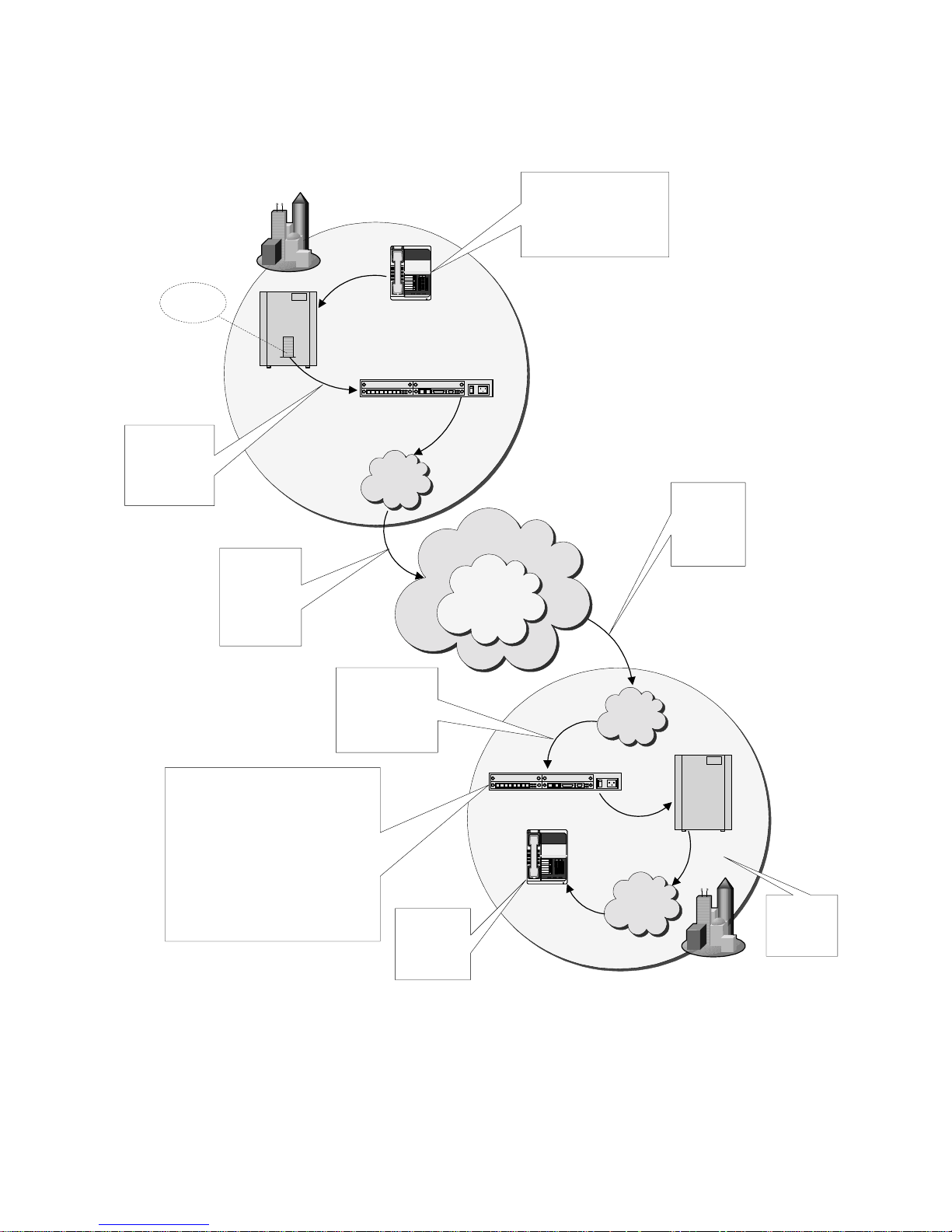
Figure 19, below, represents the call-flow in one type of Max-to-Max telephone call. Other calling
configurations are also possible.
See your reseller for Net2Phone Max-to-Max calling rates.
Page 33
Page 39
Max 8/16 and T1/E1 User’s Guide Section 4 – Using the Max Web Manager
New York City
Analog Line
Card
PBX
Switch
2.
PBX sends call
to NYC MAX's
FXO port, which
is set to IVR Off.
3.
NYC MAX
sends call via
the N2P
Network and
the Internet.
FXO port with account no. 1234123412
responds with MAX-to-MAX IVR prompt
(depending on options selected): "Please
(Caller enters a password.)
IVR continues: "Please enter the number
(Caller enters a local Lond on telephone
number, including London PBX's access
code for an outside line, such as "9";
for example, 9 123 4567.)
6.
enter your password."
you wish to call."
Figure 19 – Max-to-Max Call Flow
PBX
Extension
MAX 8/16
LAN
5.
London MAX sends
call to FXO port
with account no.
1234123412.
Telephone
connected to
line 123 4567
123
456
789
8#
*
8.
rings.
Internet
Net2Phone
Network
1.
Caller dia ls 5722, which i s
pre-set on PBX to dial
*721234123412#, account no.
of London MAX's FX O port.
LAN
MAX 8/16
123
456
789
8#
*
PSTN
Telephone
PSTN
4.
London MAX
receives call
from NYC via
the Internet.
PBX
Switch
London
7.
London PBX
sends call to
local PSTN.
Page 34
Page 40
Max 8/16 and T1/E1 User’s Guide Section 4 – Using the Max Web Manager
4.6 Routing Table Configuration
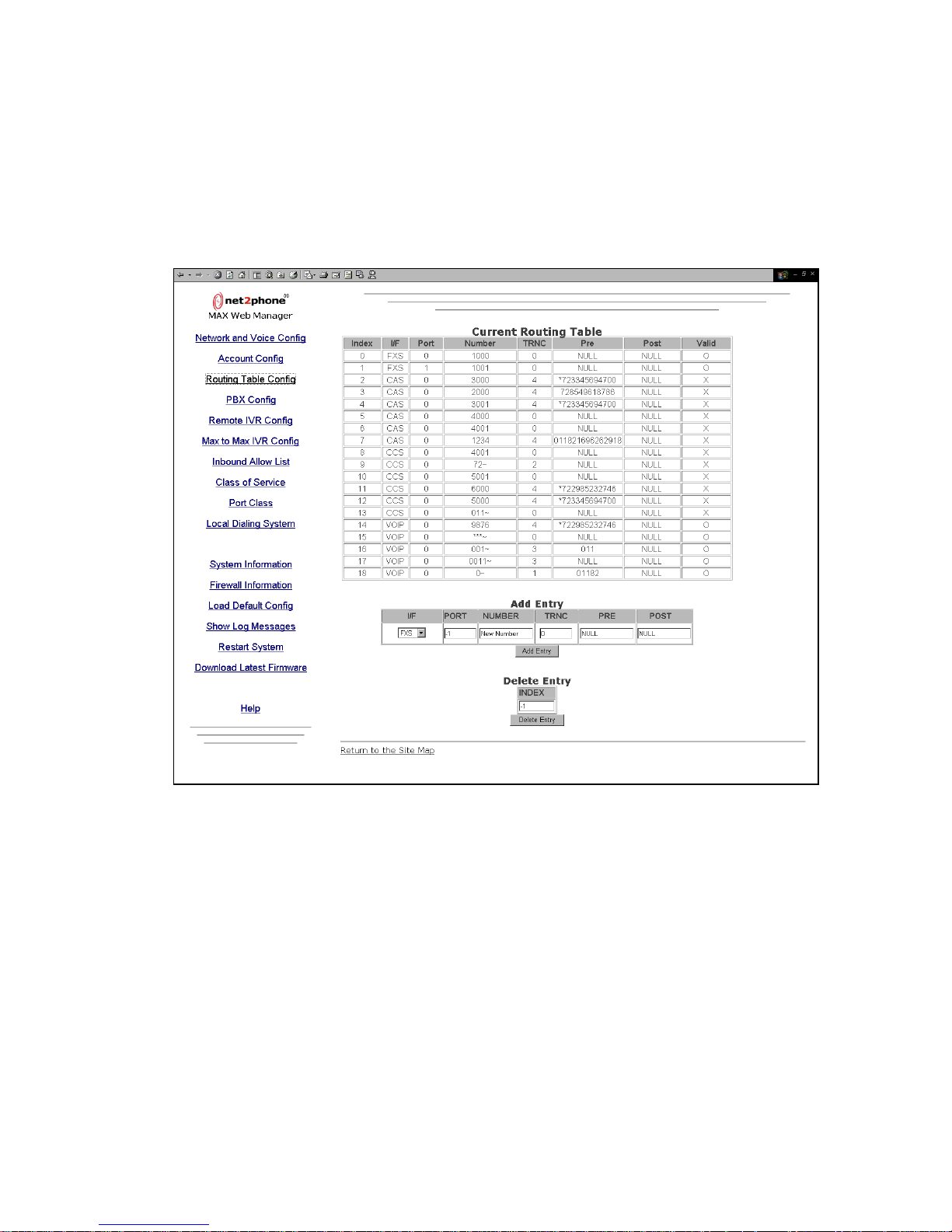
Click the Routing Table Config link to access the Current Routing Table page, illustrated
below.
Figure 20 – Current Routing Table
Many PBXs are unable to transmit the asterisk symbol ( * ) through their digital line card. The
T1/E1’s Routing Table can be configured to circumvent this limitation. In this case, when the
user dials 72 plus an account number, the Routing Table recognizes the 72 and adds a *
prefix to the number string. The N2P Network then recognizes the * 72 and places the call as
an “in network” call.
The Current Routing Table displays the following fields for each entry:
An index number (Index)
The interface type (I/F)
The logical port numbers (Port)
The phone number to be routed (Number)
Page 35
Page 41

Max 8/16 and T1/E1 User’s Guide Section 4 – Using the Max Web Manager
The truncation length (TRNC)*
The prefix number (Pre)*
The postfix number (Post)*
Validity of the table entry*
* The items marked with an asterisk are intended for special circumstances. The items should
be left unchanged in typical applications and setups.
4.6.1 Logical Port Numbering
The difference between physical and logical port numbering is that, in logical port
numbering, the FXS and FXO ports are counted separately, and the count starts
from zero instead of one. So the first FXS port will be FXS 0, and the first FXO port
will be called FXO 0.
If you have all FXS or all FXO ports:
Take the number of the port as it appears in the Account Setup page of the Max
Web Manager, and subtract one (since we count from 0 instead of 1). For
example, if you had all FXS ports, the logical port number for physical port 11
would be FXS 10 (11 – 1 = 10).
If you have both FXO and FXS ports:
Note which ports are FXS and which are FXO. If necessary, Refer to Section
4.3 in this Guide, Port Identification with the Web Manager. Write down the
physical port numbers in the table in Appendix D.
From the top left to the bottom right, count the FXS ports starting from 0, and
then count the FXO ports starting from 0. As you count, write down each port’s
logical number next to its physical number.
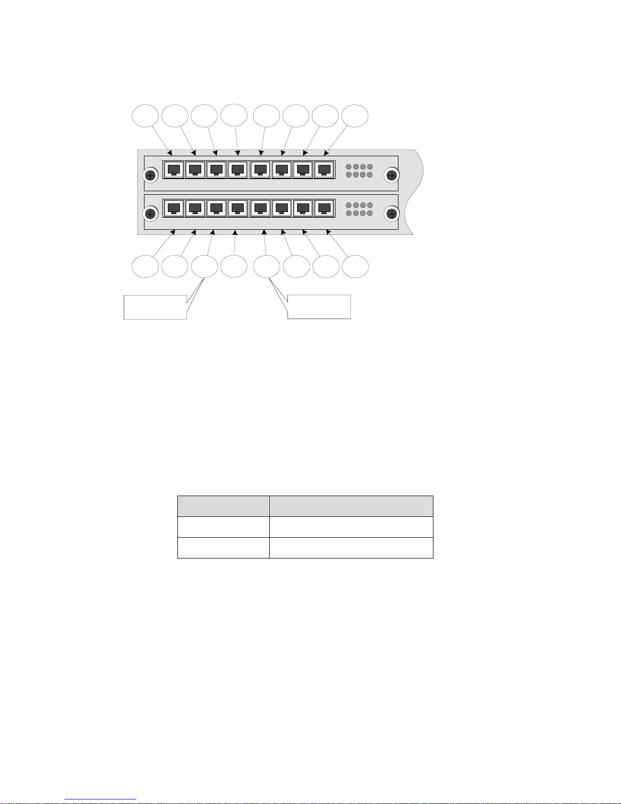
In Figure 21, for example, 3 FXO ports are present. The first one (at the upper
left) is logical port FXO 0, the second is logical port FXO 1, and the third is
logical port FXO 2.
Page 36
Page 42
Max 8/16 and T1/E1 User’s Guide Section 4 – Using the Max Web Manager
Port1Port
2
Port
3
Port
4
Port5Port6Port7Port
8
FXO FXO
AVU
FXS
AVU
Port9Port
10
FXS
1 2 3 4 5 6 7 8
FXSFXSFXS FXS
1 2 3 4 5 6 7 8
Port
Port
11
12
FXSFXS FXS
FXO
Port13Port
FXS
FXS
14
1 2 3 4
FXS
6 7
5
1 2 3 4
FXS
6 7
5
Port15Port
16
8
8
Logical Port
"FXS 8"
Logical Port
"FXO 2"
Figure 21 – Logical Port Numbering
A Physical and Logical Port Number Table, Appendix D in this Guide, has been provided
for you to write down the positions of your FXS and FXO ports so that they are available for
future reference.
4.6.2 Adding an Entry to th e Current Routing Table ** explain
To add an entry to the Current Routing Table (see Figure 20 in Section 4.6,
Routing Table Configuration):
1. In the I/F field (interface type), select the appropriate interface.
Interface type Description
FXS Interface for analog telephone
VoIP Interface for IP network
2. For the entry to apply to all the ports, enter 0 for the PORT number. Otherwise,
enter the logical port num ber that wil l corres pond with the g iven index num ber .
3. In the NUMBER field, type the number you would like to route.
4. In the TRNC field, enter the number of digits you would like truncated from the
number being dialed.
5. In the PRE field, enter the number of digits you would like added to the front
of the telephone number being truncated.
Page 37
Page 43
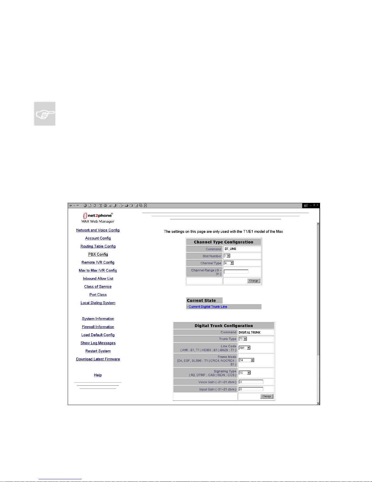
Max 8/16 and T1/E1 User’s Guide Section 4 – Using the Max Web Manager
6. In the POST field, enter the number of digits you would like added to the end
of the telephone number being truncated.
To delete an unwanted entry, simply type its index number in the Delete Entry box
and click the Delete Entry button.
NOTE: The two VoIP entries in the Current Routing Table cannot be deleted, as they are
necessary for correct operation of the Max 8/16 or T1/E1 system.
After the desired changes have been entered, click the Save button to save them.
The unit must then be rebooted as in Section 4.12.3, Restart Syst em, to activate the
new settings.
4.7 PBX Configuration
Click the PBX Config link to access the PBX Configuration page, illustrated below.
Figure 22 – PBX Configuration Page
Page 38
Page 44
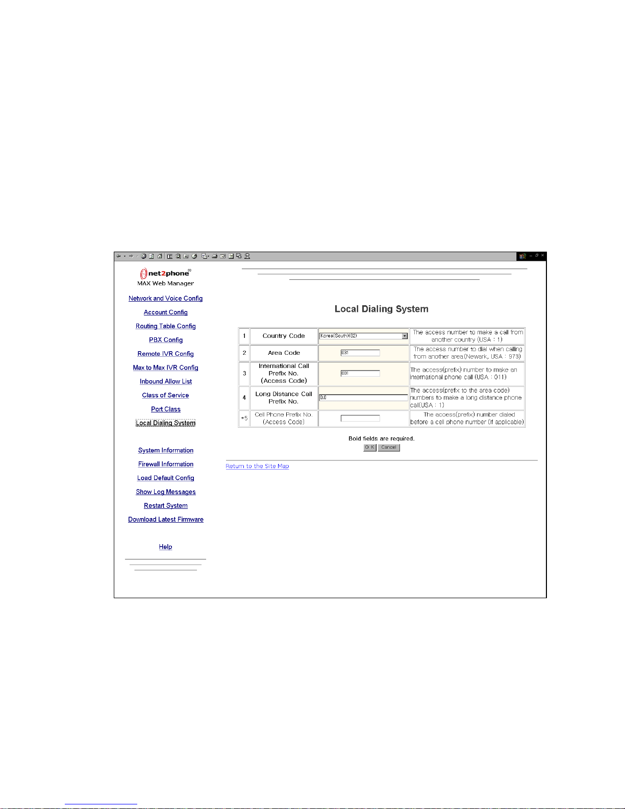
Max 8/16 and T1/E1 User’s Guide Section 4 – Using the Max Web Manager
For a detailed description of the parameters, refer to the Max Command Reference Guide.
4.8 Local Dialing System
The local dialing system feature enables the user to dial phone numbers to the Max 8/16 or
T1/E1 products as they normally do on their ordinary phone. That is, the user does not have
to dial an international call access number and country code number if the call destination is
in the same country where user lives. Similarly, the area code can be omitted for calls made
to the same area. A dialing pattern that is as close as possible to the host country's dialing
pattern can be configured by entering the following information in to Max 8/16 or T1/E1.
Figure 23 – Local Dialing Sys tem Pa ge
The country code number, area code number (city code), and international call prefix
(only single entry allowed).
The long distance call prefix number and cell phone prefix number (separate up to 10
multiple entries by a comma ( , )).
After finishing the number input, you must reset the Max 8/16 or T1/E1 to apply
modified values.
Page 39
Page 45
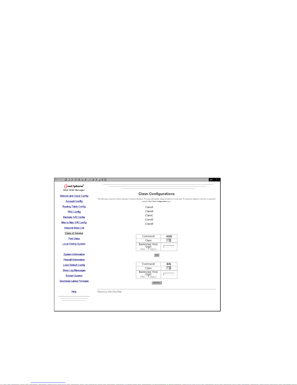
Max 8/16 and T1/E1 User’s Guide Section 4 – Using the Max Web Manager
The N2P call is made based on the local dialing system setup environment. All the
prefix numbers are automatically added to the actual dialed numbers. For example, if
the user dialed to a local phone number, the N2P call is made by the Max 8/16 or
T1/E1 with the international call access number, country code number, and area code
number added to the local phone number.
The user does not have to dial his/her telephone country code for domestic calls.
The user does not have to dial his/her telephone area code for local calls.
4.9 Class of Service Configurati on
This function is to set the call authorization classes for restricting outbound calls. There are 6
classes: A, B, C, D, E, and U. Class A has the most outbound call access capability. Class B
has the second most outbound call access capability, and so on. Applying the restricted first
digit string to a class means that the restriction is applied to all lower classes and not to
higher classes. Class U has the same meaning as OFF – there is no outbound call control.
The user inputs the restricted first digit string for each class. Users cannot make a call to the
restricted numbers that are in both his/her own class and a higher class. This feature must
work with the port class system and the local dialing system.
Figure 24 – Class Configuratio ns Page
Page 40
Page 46
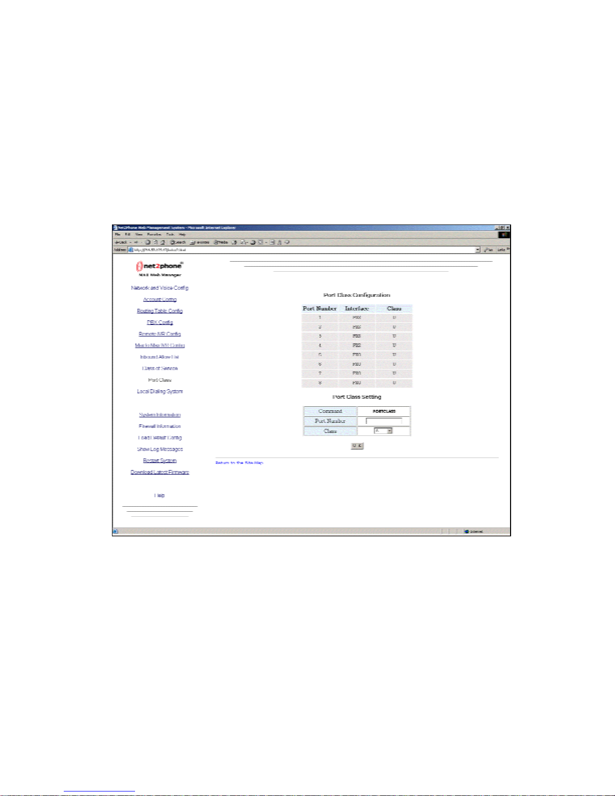
Max 8/16 and T1/E1 User’s Guide Section 4 – Using the Max Web Manager
4.10 Port Class Configuration
This function is to set call authorization class for each port to restrict outbound calls. There
are 6 classes: A, B, C, D, E, and U. Class A has the most outbound call access capability.
Class B has the second most outbound call access capability, and so on. Class U has the
same meaning as OFF – there is no outbound call control.
Refer to Section 4.8, Class of Service Configuration, for setting classes.
Figure 25 – Port Class Configuration Page
4.11 Inbound Allow List Configuration
This function blocks calls from unauthorized callers. The Max 8/16 and T1/E1 has remote
accessible ports, so an unauthorized person can use the port without admission control.
This feature allows the user to specify the allowable inbound numbers that can make use of
the port as shown in Section 4.11, Inbound Allow List Configuration, Figure 26 – Inbound
Allow List.
Page 41
Page 47
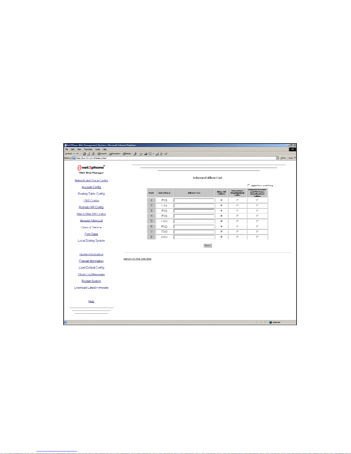
Max 8/16 and T1/E1 User’s Guide Section 4 – Using the Max Web Manager
When a call comes in to the Max 8/16 or T1/E1, it looks at the incoming caller ID, compares it
to the list for the port, and if the caller is in the allow list, admits the call through. The
maximum number of digits in the Web entry is 100. If one caller ID length is 10 digits, then
the total number of allowable callers will be 9, since the comma ( , ) occupies one digit.
There is a radio button for each port that indicates what the box should do if the caller is not
on the allow list or if the caller's phone does not support caller ID.
The options are “disconnect unauthorized caller,” “request account and PIN from
unauthorized caller,” or “allow all callers” (the default).
Figure 26 – Inbound Allow Li st
Page 42
Page 48
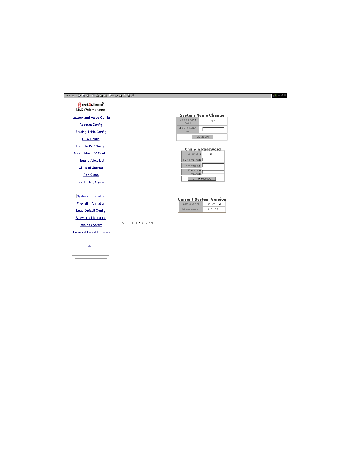
Max 8/16 and T1/E1 User’s Guide Section 4 – Using the Max Web Manager
4.12 System Information and Commands
Click the System Information link to access the System Information page, illustrated below.
Figure 27 – System Inform ation Pag e
The System Information page displays:
The Current System Name
The Current Login (user name)
The Hardware Version
The Software Version
The system manager has t he opt io ns of c hanging the system name and the c urr e nt pas sword.
To change entries on this page, just enter the new information into the desired fields, click the
Save button, and restart the Max 8/16 or T1/E1.
If changes are made on this page, the system must be restarted as discussed in Section
4.13.3, Restart System , before the changes take effect.
Page 43
Page 49
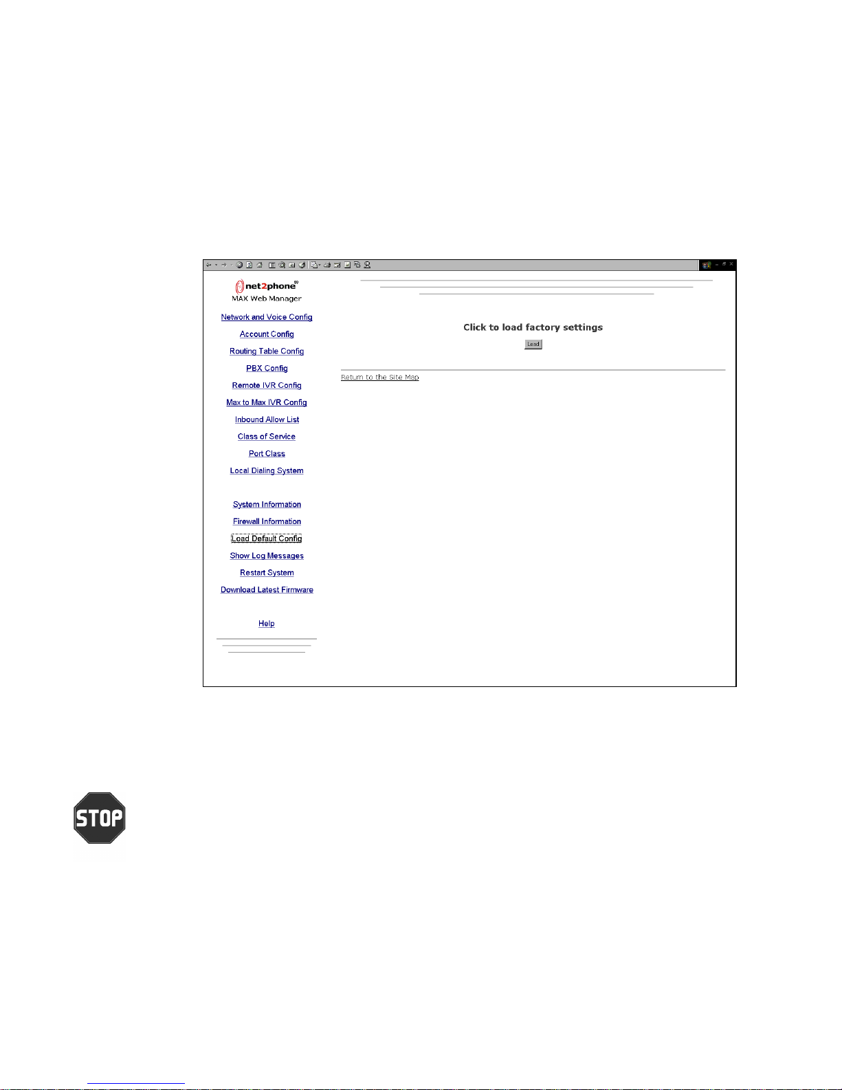
Max 8/16 and T1/E1 User’s Guide Section 4 – Using the Max Web Manager
4.13 Other Web Manager Functions
4.13.1 Load Default Confi g
Click the Load Default Config link to access the Click to load factory settings
page, illustrated below.
Figure 28 – Click to Load Fa ctory Sett ing s Page
Click the Load button to restore the Max 8/16 or T1/E1’s default factory configuration.
(Refer to the Max Command Reference Guide for system default settings.)
CAUTION: THIS COMMAND WILL DELETE ALL OF YOUR CONFIGURATION SETTINGS
AND PARAMETER VALUES.
Page 44
Page 50
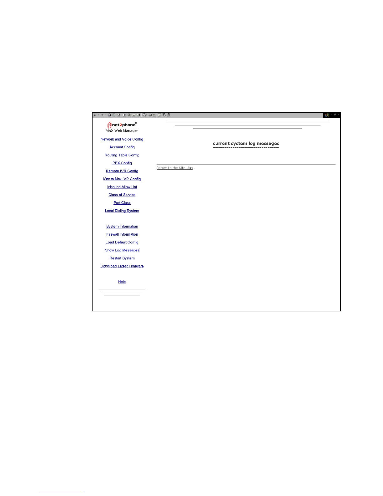
Max 8/16 and T1/E1 User’s Guide Section 4 – Using the Max Web Manager
4.13.2 Show Log Messages
Click the Show Log Messages link to access the Current System Log Messages
page, illustrated below.
Figure 29 – Current S ystem L og Messag es
Page 45
Page 51
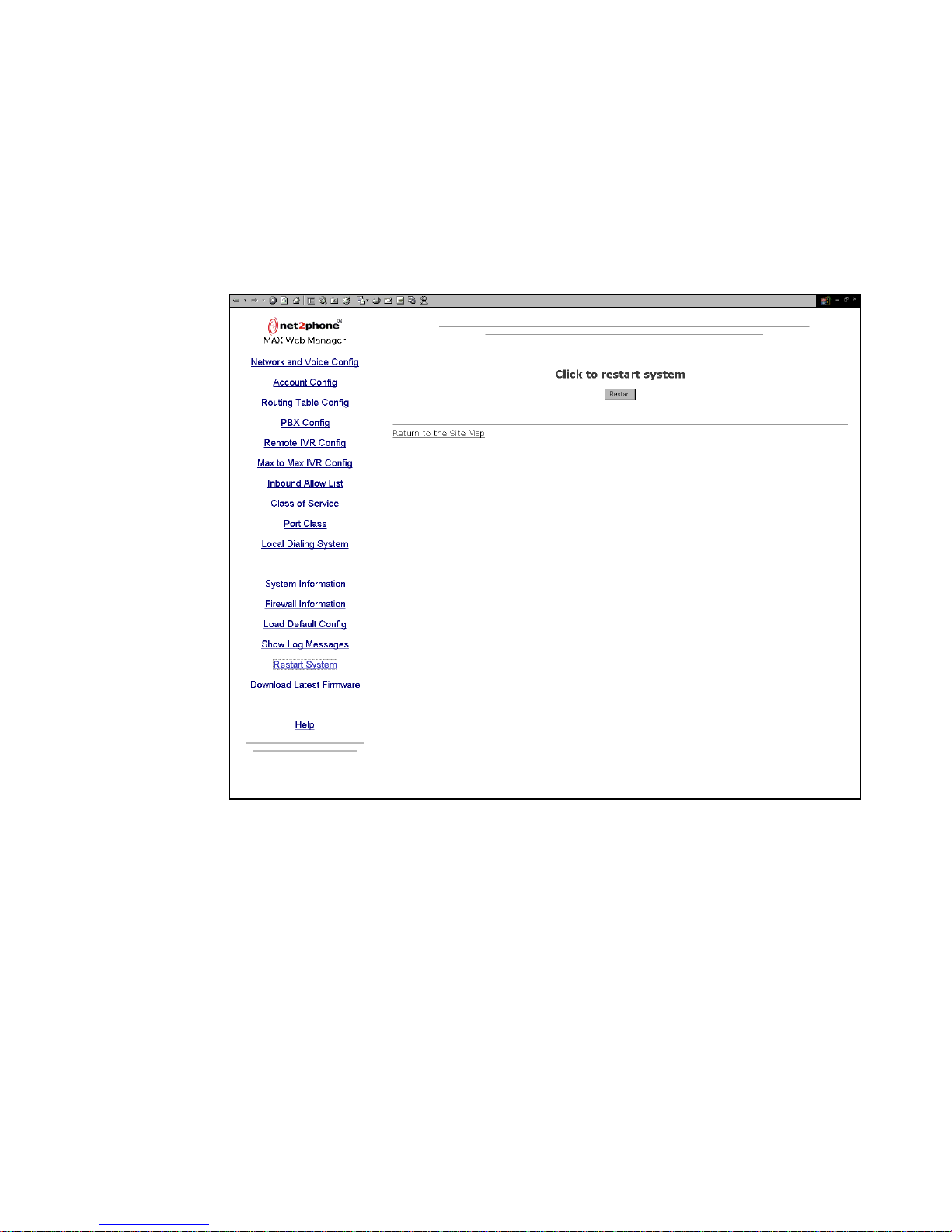
Max 8/16 and T1/E1 User’s Guide Section 4 – Using the Max Web Manager
4.13.3 Restart System
Click the Restart S ystem link to access the Restart System page, illustrated below.
To restart the system, click the Restart button.
Figure 30 – Restart Syst em Pa ge
Page 46
Page 52
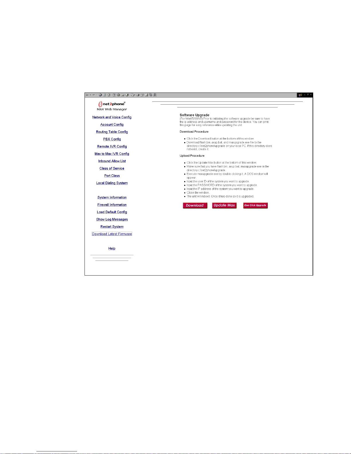
Max 8/16 and T1/E1 User’s Guide Section 4 – Using the Max Web Manager
4.13.4 Upgrading the System Software
Click the Download Latest Firm ware link to access the Software Upgrade page, illustrated
below.
Figure 31 – Software Upgr ade Page
For software versions older than v1.2.20, the software upgrade procedure for Max
8/16 or T1/E1 is divided into stages:
1. Click the Download button to download the files needed for upgrade from
Net2Phone’s FTP server to a client PC on the Max 8/16 or T1/E1’s LAN and
place the files in a folder called C:/Net2Phone/Upgrade.
2. Once the files are downloaded, click the Update Max button to upload the new
software to the Max 8/16 or T1/E1 system.
Page 47
Page 53

Max 8/16 and T1/E1 User’s Guide Section 4 – Using the Max Web Manager
For software version v1.2.20 or later, the software upgrade procedure for Max 8/16 or
T1/E1 is a one-click operation. You can simply click the One Click Upgrade button
and new software will be downloaded and then upgr a ded automatically.
4.14 Other New Features
4.14.1 Multiple Call Completion
This new feature allows users to make multiple calls without having to re-enter the
account number and PIN before every call.
1. After finishing a conversation, user A asks user B to hang up.
2. IVR will be activated and asks user A to press the # key to make another call.
If the # key is not pressed within 2 seconds, the call will be terminated.
3. User A dials the new number.
4. User A hears dial tone and waits for the other side to pick up the phone. When
the other side picks up the phone, a new call is made.
4.14.2 Call Transfer
This new feature allows users to transfer calls to other users within the Max 8/16 or
T1/E1. The Max 8/16 or T1/E1 provides the following local call transfer feature for
FXS ports in the Max 8/16 or T1/E1.
To use the local call transfer feature, the following command must be executed via a
HyperTerminal session (for the steps involved in setting up a HyperTerminal session
into the Max 8/16. please refer to section 2.1.2.1):
1. From the
SYS_NAME:/CONFIG/FXS> prompt, type:
change t3 100
This command sets the hook flash guard time to 100 milliseconds.
NOTE: The hook flash guard time must be shorter that the hook guard time but longer than 99
milliseconds.
2. While the user A and B are involved in a call, user A can press the hook flash
button.
User A hears a dial tone and user B hears hold music.
3. User A dials user C.
4. User C hears the phone ringing.
5. User A hangs up the phone once he/she hears the ring tone.
6. When user C picks up the phone, user B and user C are connected.
Page 48
Page 54

Max 8/16 and T1/E1 User’s Guide Section 4 – Using the Max Web Manager
7. If user C picks up the phone before user A hangs up the phone, user A and
user C are connected.
8. When user A hangs up the phone, user B and user C are connected.
4.14.3 Reverse Polarity for PBX Billing
The polarity reversal is supported for providing call connection time information.
The battery polarity is reversed by the Max's FXS port to indicate that a call is
connected. The polarity is reversed throughout the entire conversation. When the far
end disconnects, the battery polarity is changed back to normal by the FXS port to
indicate a call disconnect. (Some PBX systems use battery reversal indication to start
billing.)
To activate the polarity reversal feature, log into Max 8/16 or T1/E1 with the console
interface and type:
1. SYS_NAME:> /CONFIG/FXS
2. SYS_NAME:/CONFIG/FXS> change pola on
To deactivate the polarity reversal feature, log into Max 8/16 or T1/E1 with the
console interface and type:
1. SYS_NAME:> /CONFIG/FXS
2. SYS_NAME:/CONFIG/FXS> change pola off
4.14.4 IVR Modification by T1/E1/FXO Users
From version 1.2.00, the user has to create the voice prompts in *.wav format on PC
and convert the WAV files to *.axv format for downloading to Max devices. The
conversion software, vedit, is provided with the software upgrade. Refer to the Max
Command Reference Guide Addendum for more detailed instructions on modifying
the IVR (Section 29, Voice Prompt Conversion Software).
Page 49
Page 55
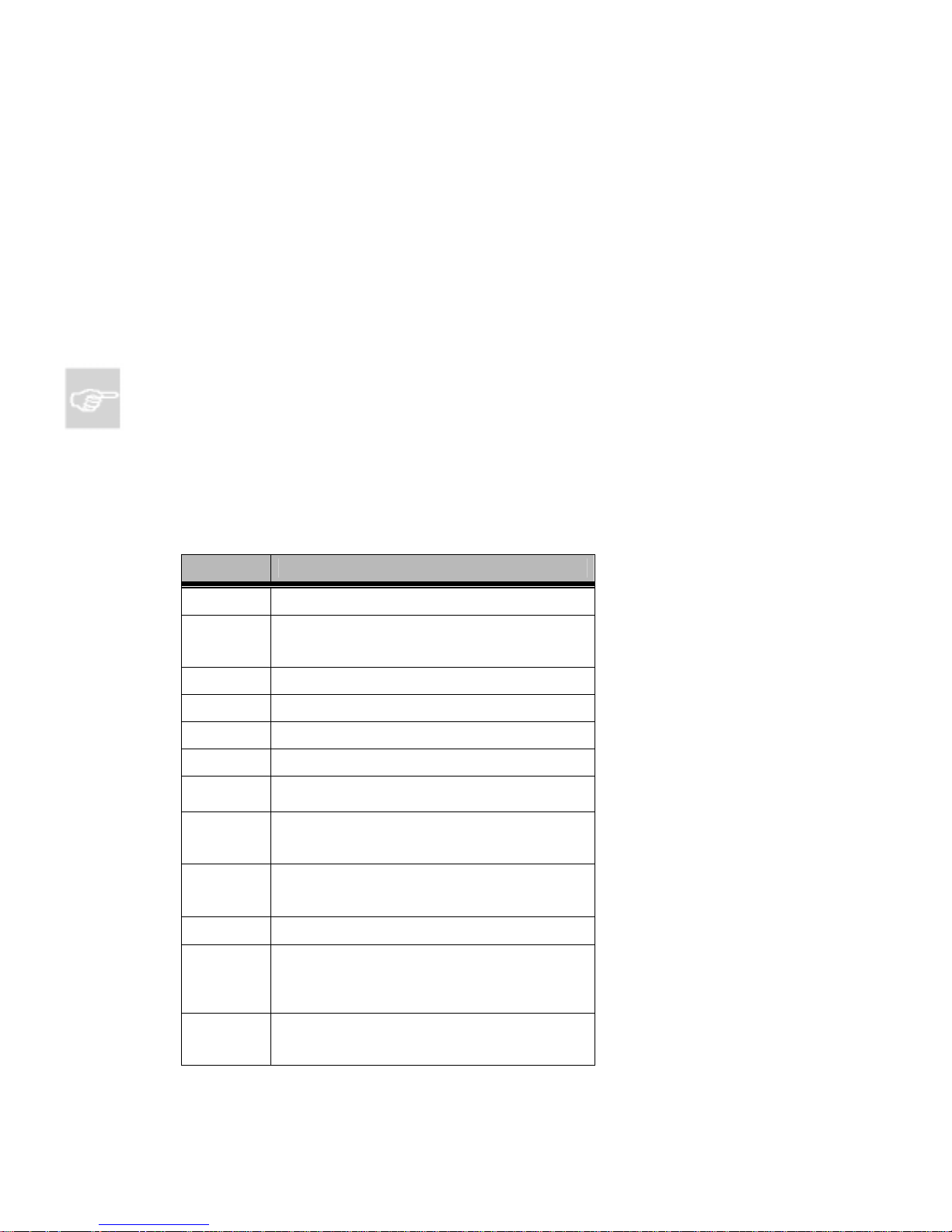
Max 8/16 and T1/E1 User’s Guide Section 5 – Configuring Voice Messages
5. Configuring Voice Messages
The Max 8/16 employs a set of default messages for the IVR voice prompts and responses callers
hear, and for the prompts and responses you hear when you configure the Max through a telephone
keypad.
If you wish, you can record custom voice message files (vocfiles) to replace the default ones. This
section will explain that procedure.
NOTE: Before attempting to record a new voice message file, review Connecting to the Max 8/16
or T1/E1 Through a Serial Cable, Section 2.1.2. in this Guide. For help with command-line
navigation, refer to Basic Command-line Navigation, Section 1 in your Max Command
Reference Guide.
5.1 Voice Message Files
The following table shows the Net2Phone Max 8/16 message file contents as shipped.
File Name Message that the file should contain
CA0000B The number you dialed is busy.
The number you are calling from is not
CA0001B
CA0002B Your call cannot be completed.
CA0003B Called party is not logged on.
CA0004B The number you called was not allowed.
CA0005B No channels are available.
CA0006B
CA0007B
CA0008B
CA0009B Your account is being used. Please try again..
CA0010B
CA0011B
authorized. Please contact your administrator for
more information.
You are using an invalid account number. Please
check the account number and try again.
The number in the forwarding field is not valid.
Please contact your administrator for more
information.
There is a problem with your Internet connection.
Please contact your administrator for more
information.
The number you are calling from is not
authorized. If you have an account number press
#. Otherwise, contact your administrator for more
information.
You have dialed a number that has been
restricted by the Max administrator. Please try
again.
Page 50
Page 56
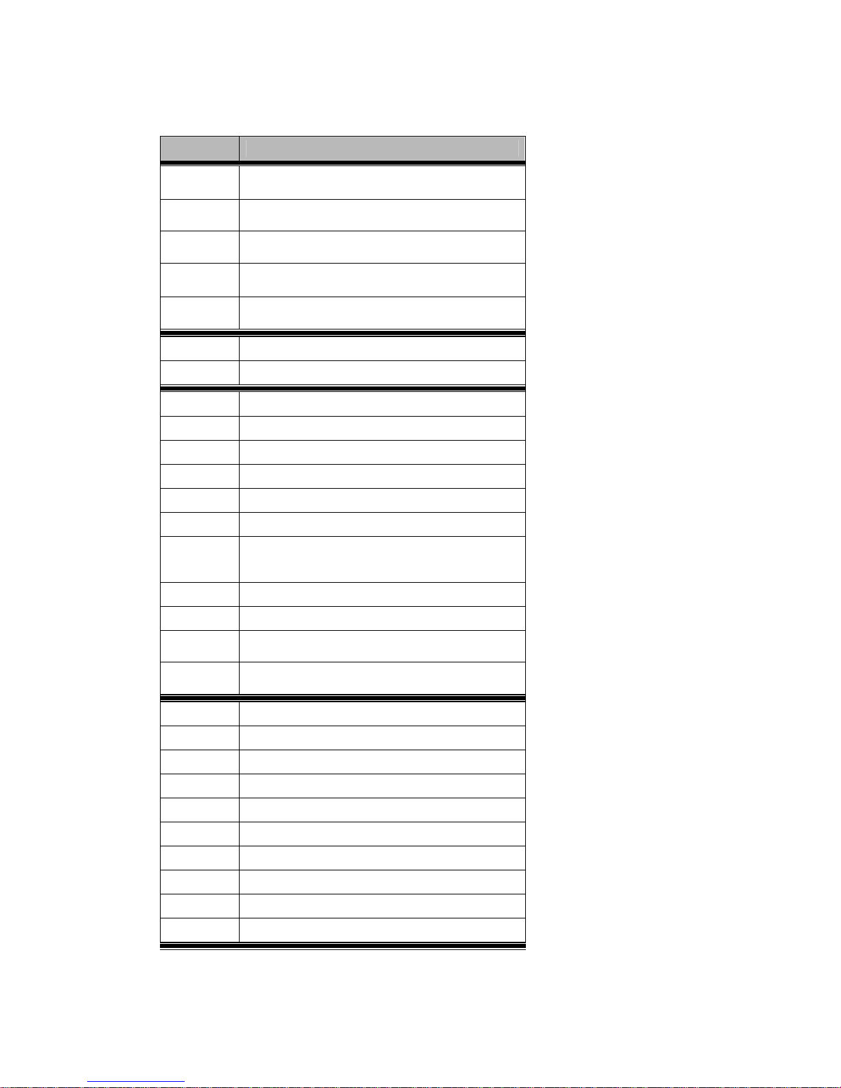
Max 8/16 and T1/E1 User’s Guide Section 5 – Configuring Voice Messages
File Name Message that the file should contain
CA0012B
CA0013B
CA0014B
You have dialed an invalid number. Please press
# to try again.
The person you are trying to call is already
making a PC-to-PC call.
Your account is disabled. Please check the
account number and try again.
CA0015B Please press ### to complete the call or hang up.
CA0016B
Your call is disconnected from IP address change
in DHCP. Please try to call later.
TN0001Z Hold Music
TN0002Z Wait Music
SN0000B Welcome to Net2Phone.
SN0001B Thank you for using Net2Phone.
SN0002B Please enter your password.
SN0003B Your password is incorrect. Please try again.
SN0004B Please enter the number you wish to call.
SN0005B Please enter your account number.
You do not have sufficient funds for this call.
SN0006B
Please contact your administrator to recharge
your account.
SN0007B You must be logged out before you trying to call.
SN0008B Please enter your PIN.
SN0009B
Welcome to Net2Phone. Please enter the
number you wish to call.
SN0010B Goodbye and thank you for using Net2Phone.
FE0000B Feature Complete (Dingdong) –Optional
FE0001B Please, enter your IP address.
FE0002B Your IP Address is
FE0003B Please, enter your netmask.
FE0004B Your net mask is
FE0005B DHCP is now enabled, please press #.
FE0006B DHCP is now disabled, please press #.
FE0007B You have
FE0008B Remaining in your account
FE0009B Please, reboot your Max
Page 51
Page 57

Max 8/16 and T1/E1 User’s Guide Section 5 – Configuring Voice Messages
File Name Message that the file should contain
DG0000B Zero
DG0001B One
DG0002B Two
DG0003B Three
DG0004B Four
DG0005B Five
DG0006B Six
DG0007B Seven
DG0008B Eight
DG0009B Nine
DG0010B Ten
DG0011B Eleven
DG0012B Twelve
DG0013B Thirteen
DG0014B Fourteen
DG0015B Fifteen
DG0016B Sixteen
DG0017B Seventeen
DG0018B Eighteen
DG0019B Nineteen
DG0020B Twenty
DG0030B Thirty
DG0040B Forty
DG0050B Fifty
DG0060B Sixty
DG0070B Seventy
DG0080B Eighty
DG0090B Ninety
DG0100B Hundred
DG0101B Thousand
DG0102B
Dot (.)
DG0103B Dollar
DG0104B Cent
Page 52
Page 58

Max 8/16 and T1/E1 User’s Guide Section 5 – Configuring Voice Messages
File Name Message that the file should contain
DG0105B And
DG0106B Minute
5.2 Recording a Custom Voice Message Fi le
1. Connect an analog telephone to FXS port #1 on the Max 8/16 or T1/E1. (If you need help
with port numbering, refer to Physical Port Numbering, Section 1.5.1.)
2. Establish a serial connection from your PC to the Max 8/16. (Refer to Connecting to the
Max 8/16 Through a Serial Cable, Section 2.1.2.)
3. Change the current directory to
n2p:test/vocfile>. (For help with navigating at a
command line, see the Max Command Reference Guide, Section 1.)
NOTE:
root directory prompt will contain the new name you assigned, instead of
n2p is the Max’s default system name. If you have assigned a new system name, your
n2p. For example,
my_name:test/vocfile>.
4. Lift the telephone handset.
5. Type
record <file number> <recording time in sec> at the command line on the PC.
Recording starts as soon as the Enter k e y is pressed, and ends after <rec or ding t ime in
sec> seconds.
6. Type
play <file number> to check the recorded message. If the recording is incorrect
or a different message is desired, repeat Step 5.
7. After you create (or upload) a new file, you must save it to NV (Non-Volatile) memory. To
save the file, change the current directory to
n2p:config> and type save.
The new vocfile is not activated until you reboot the Max 8/16 system.
8. Reset the system using one of the three options:
Type
/system/reset at the command line.
Power-off the unit, wait 10 seconds, and turn it on again.
Use the Restart System link in the Web Manager, as described in Section 4.13.3.
9. To confirm that the new message is functioning, dial ***1 from the telephone.
5.3 Voice Message File Upload/Download Procedure
To implement the file upload/download procedure, you will need:
a PC with LAN connection to Max 8/16 or T1/E1
the DOS FTP client program (included with all Microsoft operating systems).
Page 53
Page 59
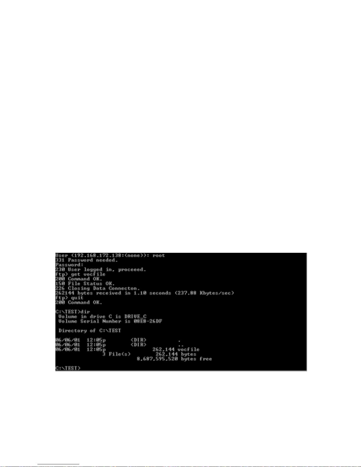
Max 8/16 and T1/E1 User’s Guide Section 5 – Configuring Voice Messages
the Max 8/16 or T1/E1 voice message binary file, “vocfile” (for upload)
5.3.1 Voice Messag e Fi l e Download Procedure
1. Power-on the Max 8/16 system and wait until the “OPR” LED begins to blink.
2. Obtain the Max 8/16’s current IP address (see Section 2 in this Guide).
3. On your PC, open a DOS window or Command prompt.
4. Go to the PC directory to which you want to download the vocfile.
5. Establish an FTP connection with the Max 8/16 as follows: from the DOS prompt,
type ftp, a space, and the IP address of the unit followed by the Enter key. Fo r
example: ftp 192.168.172.19 Enter (use your Max 8/16’s IP address).
6. At the User <192.168.172.138:<none>> prompt, enter the default User
Name, root, followed by the Enter key.
7. When prompted for a password, enter the default password,
n2p, followed by
the Enter key. The password does not display on the screen as you type it.
8. At the
FTP> prompt, type get vocfile, followed by the Enter key.
You may now access the vocfile in the directory to which it was downloaded.
Figure 32, below, illustrat es the FT P file do wnlo ad pr ocedur e.
Figure 32 – File Download Procedure
Page 54
Page 60

Max 8/16 and T1/E1 User’s Guide Section 5 – Configuring Voice Messages
5.3.2 Voice Messag e Fi le Upload Procedur e
1. Proceed as in steps 1 – 7 in Section 5.3.1, above.
2. At the prompt, type
put vocfile, followed by the Enter key. The new
vocfile is not activated until you reboot the Max 8/16 system.
3. To save the file and reboot the Max 8/16 or T1/E1, proceed as in steps 8 – 10
in Section 5.2, Recording a Custom Voice Message File, above.
Page 55
Page 61

Max 8/16 and T1/E1 User’s Guide Section 6 – Placing Calls
6. Placing Calls
6.1 The Pound Key
The pound key (#) is used by the Max to indicate the end of a dial string. If the pound key is
omitted, the Max waits three seconds for additional input, then places the call. This delay is
adjustable through a HyperTerminal connection. For details, see Sections 10 and 11 in the
Max Command Reference Guide.
6.2 Placing Calls to the PSTN
6.2.1 Placing calls to destinations within North America
Pick up the handset on a telephone connected to one of the Max 8/16’s ports and dial
1 + the area code + the local number, followed by the # key. For example, if the area
code is 212 and the local number is 555-6791, you would dial 1 212 5556971 #.
6.2.2 Placing internation al cal l s
Pick up the handset and dial 011 + the country code + the city code + the local
number, followed by the # key. For example, if the country code is 9, the city code is
81 and the local number is 223-4567, you would dial 011 9 81 2234567 #.
6.3 Max-to-Max Callin g
6.3.1 Calling a Max 8/16 or T1/E1’s FXS port from anot her Max
If you are placing a call from a telephone connected to your Max’s FXS port in New York City
to a telephone connected to a Max’s FXS port in Los Angeles, and the account number
assigned to the remote Max’s port is 1234567890, the dialing procedure is:
1. Dial *72 1234567890 #.
2. The telephone attached to the port in Los Angeles rings.
6.3.2 Calling a Max 8/16’s F XO port from another Max
Let us imagine that you are planning a trip to England and you need to call Windsor Castle’s
24 hr. information line. To call from London, you would dial 0753 (the city code) + 831118 (the
local number). To place the call directly from your PBX extension in your office in the US, you
would dial 011 01 753 831118 (omitting the 0 before the city code).
We will place the call as a Max-to-Max call, using the Max 8/16 in your company’s New York
City office and the Max 8/16 in your company’s London office.
Before we place the call, let us assume the following conditions.
Page 56
Page 62

Max 8/16 and T1/E1 User’s Guide Section 6 – Placing Calls
On the New York City (local) Max unit:
Four FXO ports on the New York City Max have been configured for Max-to-
Max calling and their Max-to-Max IVR setting is IVR Off.
Extension number 4000 on the PBX has been assigned to this group. The
group is configured on the PBX as a hunt group so that, when 4000 is dialed
from an extension on the PBX, the PBX connects the caller to the first available
unoccupied port on the Max within the group.
On the London (remote) Max unit:
The account number of the London unit is 1234567890.
The Welcome and Password option has been selected on that unit’s Max-to-
Max IVR Config table.
Now we can proceed with the call.
1. Dial 4000 from your office PBX extension.
You hear an Internet dial tone.
2. Dial *72 + the remote FXO port’s account number, e.g., *72 1234567890 #.
The Max in the London office greets you, “Welcome to Net2Phone. Please
enter your password.”
3. Enter the password.
The Max in London responds, “Please enter the number you wish to call.”
4. Enter Windsor Castle’s city code and local number as if you were dialing an
inter-city call from London: 0753 831118.
The voice prompts you receive from the remote unit would depend on how its Max-toMax IVR options were configured. Depending on the options set by the remote
system’s manager:
you might immediately be asked for a number you wish to call,
you might be asked for a password, or
your call may be automatically forwarded to another number (without any
notification to you).
NOTES:
If the LAN to which either Max is connected employs a firewall, you need to configure
settings on both the Max unit and the firewall before you can place Max-to-Max calls. For
information about configuring a firewall, refer to Section 4.1.1, Configuring Firewalls.
In Max-to-Max calling, the receiving port’s Account Information table settings must be
configured to permit it to receive calls. For details, refer to Section 4.4.2.2, Recei v in g Max-
to-Max Calls, in this Guide.
Refer to your Reseller for information about Net2Phone’s Max-to-Max calling rates.
Page 57
Page 63

Max 8/16 and T1/E1 User’s Guide Appendix A – The PBX Interface Cable
APPENDICES
Appendix A – The PBX Interface Cable
The cable used to connect the Max’s T1/E1 port to the PBX’s T1/E1 consists of a length of RJ-48 STP3
(Shielded Twisted Pair class 3) cable with a shielded RJ-45 male connector at each end, wired as per the
following table.
Common CAT5 cable and connectors may be used as an alternative to shielded cable, but they do not provide
protection from interference where the cable run is lengthy or sources of electromagnetic radiation are present.
Signal RJ-48 Pin
RX (input) 1
RX (input) 2
NC (not connected) 3
TX (output) 4
TX (output) 5
NC 6
NC 7
NC 8
Signal Wiring Diagram
The following table illustrates the cable wiring as used on Net2Phone’s Nortel Meridian PBX.
RJ-48 (a) Pins RJ-48 (b) Pins
1 5
2 4
4 2
5 1
3 3
6 6
7 7
8 8
Cable Wiring Diagram for the Nortel Meridian PBX
Page 58
Page 64
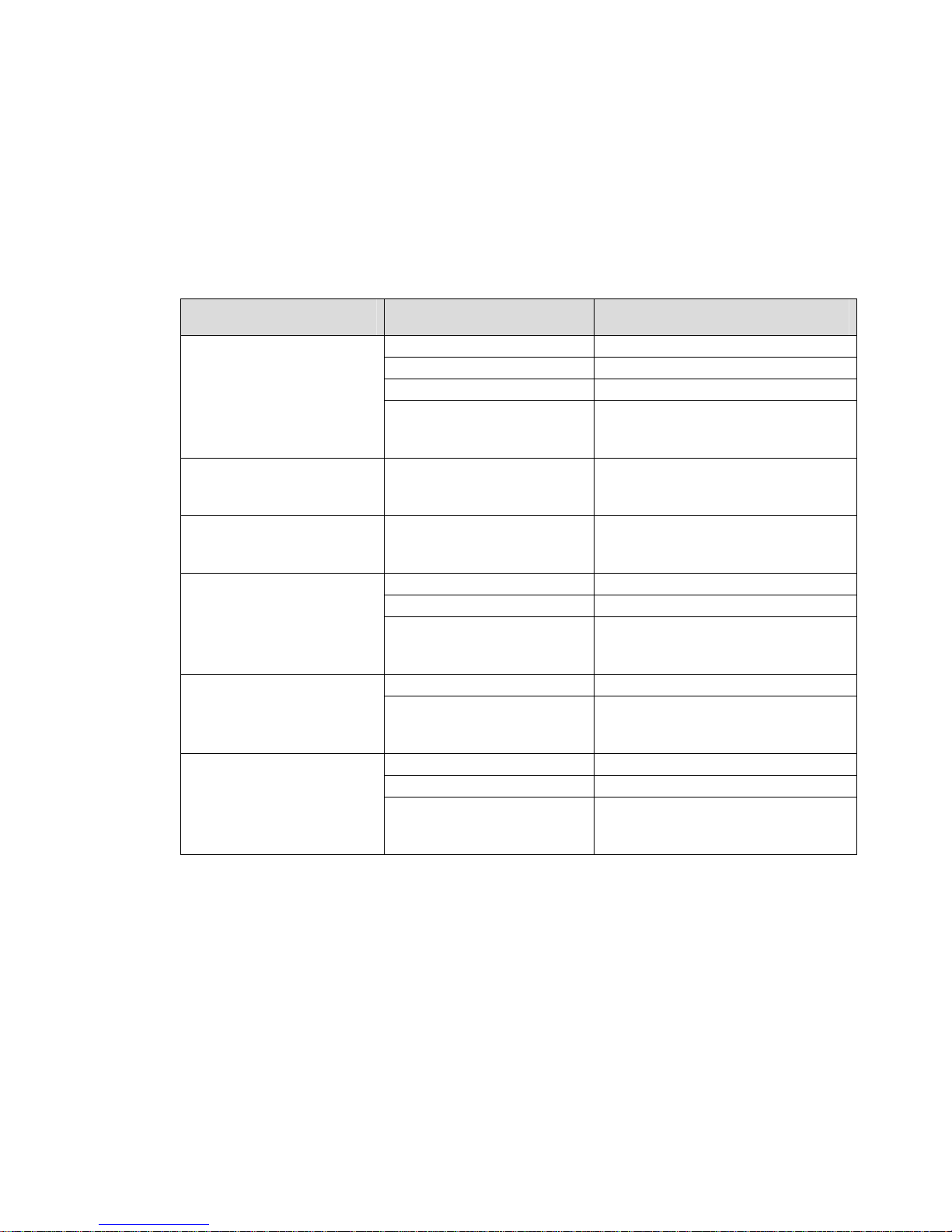
Max 8/16 and T1/E1 User’s Guide Appendix B – Troubleshooting
Appendix B – Troubleshooting
B. 1 Common mechanical in stal l ati on problems and corrective actions
If there appears to be a malfunction, first check all cables and connections. If these appear to
be in order, see the following table for specific troubles and solutions.
Symptom Possible Cause Corrective Action
Power LED and fan are off
Power LED on; fan off Faulty N2P Max 8/16 or
Power LED off; fan on Faulty N2P Max 8/16 or
No initialization response
from N2P Max 8/16
operating for some time
Console screen display
freezes
Power source switched off Switch power source ON
Faulty power cable Check/replace power cable
Faulty power source Check/correct input power
Faulty internal power supply Contact Net2Phone Technical
Service Center or your Net2Phone
reseller
Contact Net2Phone Technic al
T1/E1
Service Center or your Net2Phone
reseller
Contact Net2Phone Technic al
T1/E1
Service Center or your Net2Phone
reseller
Faulty console terminal Check/replace terminal
Faulty cabling to terminal Check/replace cable
Faulty N2P Max 8/16 or
T1/E1
Contact Net2Phone Technic al
Service Center or your Net2Phone
reseller
Overheating Check ventilation Unit shuts off after
Faulty N2P Max 8/16 or
T1/E1
Contact Net2Phone Technic al
Service Center or your Net2Phone
reseller
Console fault Reset/replace console
Software error Repeat power-up procedure
Faulty N2P Max 8/16 or
T1/E1
Contact Net2Phone Technic al
Service Center or your Net2Phone
reseller
Page 59
Page 65

Max 8/16 and T1/E1 User’s Guide Appendix B – Troubleshooting
B. 2 Common networ k connection problems
When I attempt to connect to my Net2Phone Max 8/16 through a serial cable
connection, I do not see any text, or the text that appears is distorted.
Make sure the connection settings are as follows:
Baud rate
Parity
Character size
Stop Bit
Flow Control
19200
None
8
1
None
Make sure the serial cable is connected and fastened to both the Net2Phone
Max 8/16 and your computer.
My network supports DHCP, but my Max 8/16 cannot obtain correct network
settings.
Make sure DHCP is enabled.
Make sure the RJ-45 LAN cable is connected securely to your Net2Phone Max
8/16 and LAN, hub, or router.
Make sure that all network ports, routers, or hubs are live.
I set DHCP to ON, but my Net2Phone Max 8/16 cannot obtain correct network
settings.
Make sure your network supports DHCP.
Make sure your RJ-45 LAN cable is securely connected to both the Max 8/16
and to the LAN, hub, or router.
Make sure that all network ports, routers, or hubs are live.
My analog phone does not have a period; how do I enter the periods in my IP
address and netmask?
Use the star key (*) in place of the periods.
Page 60
Page 66

Max 8/16 and T1/E1 User’s Guide Appendix B – Troubleshooting
When I enter a static IP Address into my Net2Phone Max 8/16 and restart the
unit, the IP Address I entered is not saved.
Make sure DHCP is set to OFF.
If you entered the IP address through an analog phone, make sure you press
the # key before hanging up.
I changed the login password on my Max 8/16 and I forgot the new password.
Log in as manager or sysadm. Note that the default password for both is n2p.
When I attempt to access the Max Web Manager, I am prompted for a user
name and password. But when I enter them and press the OK button, the
Password page reappears.
Make sure both the user name and password are correct (Note that the user
name and password are case sensitive.)
B. 3 Common confi guration problems
In the Max Web Manager Network and Voice Configuration page, I omitted the
DNS server field because it does not apply to me, but now the Max Web
Manager will not let me save the settings.
The DNS fields must not be left blank. If you do not wish to enter DNS Servers,
you must enter 0.0.0.0 in th ose fields .
In the Max Web Manager’s Account Configuration page, I accidentally checked
the “Use account for all fields” check-box and saved the changes. Now the
different accounts I had in each port are no longer present. How can I put them
back?
You must make sure the Use account for all fields checkbox is unchecked,
and enter the account inform ation again m anua lly.
When I dial the extension that I routed to port 1, it rings port 2, and when I dial
the extension I routed to port 2, it rings port 3, etc…
In the Routing Table Configuration page, make sure you routed each extension
to the logical port number of the desired port, not the labeled or physical port
number. To find the logical port number for each port, refer to Section 4.5.1,
Logical Port Numbering.
Page 61
Page 67

Max 8/16 and T1/E1 User’s Guide Appendix B – Troubleshooting
B. 4 Problems using the Max 8/16
When I attempt to make a call, I hear a fast busy signal.
Click the Show Log Messages link to access the Current System Log
Messages page (Section 4.7). Then check to see if 00 REL
DM_NOT_SPECIFIED is displayed. This would indicate that the doorman
servers cannot be found. Make sure that the DNS server IP parameter values
(Section 4.2) are correct so that the doorman can be reached.
When I attempt to call into my Net2Phone Max 8/16 from another unit via *72, I
get a busy signal.
Make sure the account number you are calling from is valid and has a correct
PIN.
Make sure the account you are calling from has sufficient funds.
Make sure you entered the correct number to be dialed.
Make sure you entered *72 before the number.
If the port you are calling is sharing an account number with other ports, make
sure that only the port you dialed is set to Login in the Account Information
table. See Configuring Accounts, Section 4.3 in this Guide.
When I attempt to make a call from either an FXS or FXO port, I get immediately
disconnected.
Use the ping command to determine that the Max’s connection to the LAN is
functioning. The ping command is discussed in Section 2.3.2 of this Guide,
Entering an IP Address.
Make sure that an account number has been entered for the port from which
you are calling, and that there are funds in the account. This topic is covered in
Configuring Accounts, Section 4.3 in this Guide.
Page 62
Page 68

Max 8/16 and T1/E1 User’s Guide Appendix C – Technical Support
Appendix C – Technical Support
If you are experiencing a technical problem, please refer to Appendix A, Troubleshooting, in this
Guide. If the problem remains unresolved, please contact your reseller for assistance.
Do not attempt to disassemble the Net2Phone Max 8/16 aside from removing the AVU cards.
There are no user-serviceable parts inside the unit.
Do not remove individual ports from the AVU cards.
Page 63
Page 69

Max 8/16 and T1/E1 User’s Guide Appendix D – System Specifications
Appendix D – System Specifications
Analog voice interface
FXS, RJ-11 (if present)
LAN interface
Serial interface
LED indicators
VoIP protocol
Voice processing capabilities
{compression/decompression}
{QoS related capabilities}
Management interface
Physical Size (H x W x D)
Weight
Input power
Main processor
Operation temperature
Storage temperature
Operation humidity 5 ~ 95 (NOTE: non-condensing)
Noise level
Ringer Equiv. No.
10/100baseT, RJ-45, 1 port
{Ethernet/Fast Ethernet auto-detection}
EIA-232 {old RS-232C}, DB-9, 1 port
Asynchronous serial communication at 19200bps
one active status indicator for system
one alarm indicator for system malfunction
one active status indicator for each analog voice port
one Fast Ethernet indicator
one LAN link indicator
one LAN data receive indicator
one serial port transmit indicator
one serial port receive indicator
one voice transmit indicator
one voice receive indicator
Net2Phone proprietary protocol
G.711
G.723.1
Echo Cancellation(G.168)
Voice Activity Detection
Comfort Noise Generation
Command line interface via console port or telnet client
Web interface via any Web browser
45 x 439 x 310 mm
{mounting handles for a 19-inch rack are available}
2 Kg.
100 - 240 VAC, 1.5 A (max.),
50/60 Hz , 50 W (max.)
Motorola MPC855T
0 ~ 50o C
40 ~ 85o C
15 dB @ 1 m
0.5B
Page 64
Page 70

Max 8/16 and T1/E1 User’s Guide Appendix D – System Specifications
LED Meaning LED Meaning LED Meaning
ALM Alarm OPR Operational 10/100 Fast Ethernet
LINK Link active LRX Receive data STX Serial port transmit
SRX Serial port receive TXHW Voice transmit RXHW Voice receive
Page 65
Page 71
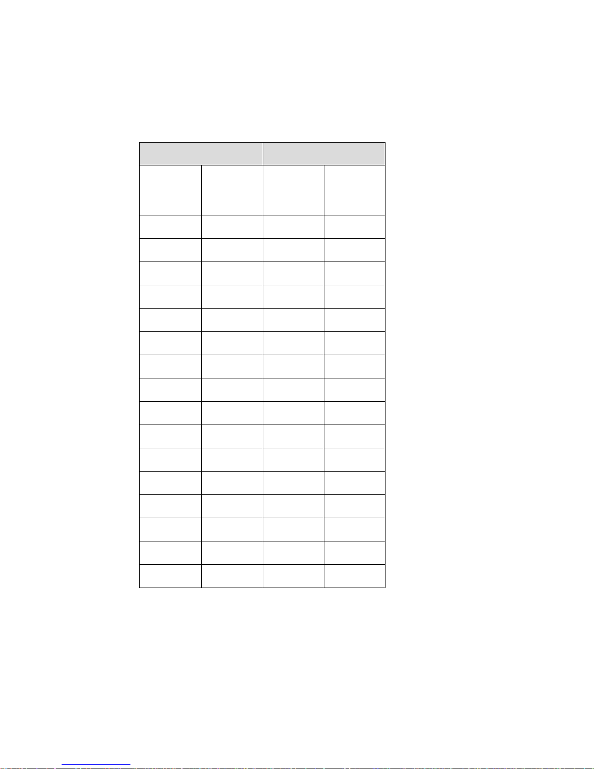
Max 8/16 and T1/E1 User’s Guide Appendix E – Physical and Logical Port Number Table
Appendix E – Physical and Logical Port Number Table
FXS Ports FXO Ports
Physical
Port
Number
Logical
Port
Number
Physical
Port
Number
Logical
Port
Number
Page 66
Page 72
Max 8/16 and T1/E1 User’s Guide Appendix F – Approvals and Listings
Appendix F – Approvals and Listings
FCC Declaration of Conformity
Product name: Net2Phone Max 8/16 an d T1/E1
FCC Rules: Tested to comply with FCC part 15, Class B
Operating environment: for home or office use
FCC Compliance Statement:
This device complies with part 15 of the FCC Rules. Operation is subject to the following two
conditions: (1) This device may not cause harmful interference, and (2) this device must accept any
interference received, including interference that may cause undesired operation.
E176683
/ , 67 ('
/ , 67 ('
/ , 67 ('/ , 67 ('
,7(
,7(
,7(,7(
27
EA
E176683
Approval Number: CE168X ART:99663 Z
Important! Changes or modifications not expressly approved by the manufacturer could void
the user’s authority to operate the equipment. Use with an approved telephone set.
Party responsible for product compliance:
Net2Phone, Inc.
520 Broad Street
Newark, NJ 07102
USA
Page 67
Page 73

Max 8/16 and T1/E1 User’s Guide Index
Index
Account Configuration page .......................27
accounts................................................ 27, 62
AVU....................................................... 26, 64
broadband..................................................... 1
browser....................................................... 19
default gateway address............................. 22
DHCP............................10, 13, 14, 15, 17, 22
DNS server addresses................................ 22
domain name.............................................. 22
factory configuration ................................... 45
firewall.......................................22, 24, 32, 58
gateway-server .............................................1
hunt group ................................................... 58
HyperTerminal ............................................11
I/F................................................................ 36
index number........................................ 36, 39
interface type ..............................................36
IP address...........................10, 11, 15, 16, 19
IP Configuration table ................................. 21
IP parameters .....................11, 13, 15, 17, 63
Jitter Buffer Bounds .................................... 21
LAN.............................................1, 10, 22, 48
Load Default ............................................... 45
logical port number .........................36, 37, 62
Login Button................................................ 28
Max to Max .24, 26, 28, 29, 32, 33, 34, 57, 58
multiple account.................................... 27, 28
net mask address........................................15
Network and Voice Configuration page ......21
Network Configuration...........................22, 24
Network Configuration table........................22
Network Password ......................................20
Number........................................................36
password.........................................12, 20, 62
phone number.............................................36
physical port number.............................37, 62
physical ports ..............................................25
Ping .............................................................18
Placing Calls................................................57
Port..............................................................36
Port Numbers..............................................22
Post.............................................................37
postfix number.............................................37
Pre...............................................................37
prefix number ..............................................37
proxy server caching.....................................3
PSTN...........................................1, 30, 33, 34
Receiving Calls................................28, 32, 34
Remote IVR.....................................25, 26, 30
Restart System page.............................22, 47
Routing Table............................36, 39, 40, 62
Save button...........................................25, 39
serial cable ......................................11, 12, 19
serial cable connection......................4, 10, 61
Show Log Messages page..........................46
Site Map page .............................................20
Software Upgrade .......................................48
software upgrade procedure .................48, 49
Static .....................................................13, 22
System Information page ............................44
system name...............................................44
telephone.....................................................68
telephone keypad............................10, 13, 14
TRNC ..........................................................37
truncation length..........................................37
Page 68
Page 74

Max 8/16 and T1/E1 User’s Guide Appendix D – System Specifications
upgrade................................................. 48, 49
User ID........................................................ 12
user name............................................. 44, 62
vocfile ........................................51, 54, 55, 56
Voice Configuration.........................21, 24, 62
Voice Message............................................51
VoIP.........................................................1, 39
Page 69
Page 75

Net2Phone, Inc.
520 Broad Street
Newark, NJ 07102
USA
Tel: 1-877-393-VOIP(8647)
email: [email protected]
Printed in Korea
 Loading...