

Page 1
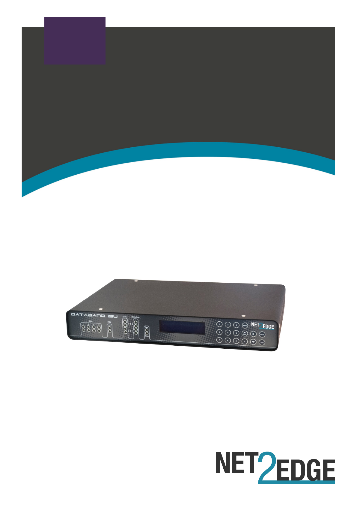
QSG
Quick Start Guide:
DataBand ISU
Page 2
QSG | Quick Start Guide: DB-ISU
| www.net2edge.com
2
Trademarks
All trademarks and registered trademarks are the property of their respective owners.
Copyright Notice/Restrictions
Copyright © 2016 Net2Edge Limited all rights reserved.
No part of this work may be reproduced or used in any form or by any means (graphic,
electronic or mechanical) without written permission from Net2Edge.
The information contained herein is confidential property of Net2Edge Limited. The use,
copying, transfer or disclosure of such information is prohibited except by express
written agreement with Net2Edge Limited.
Revision History
Rev
Date
Description
2
2nd September 2016
Rebranded & Minor Amendments
Page 3

QSG | Quick Start Guide: DB-ISU
| www.net2edge.com
3
Contents
Trademarks .................................................................................................. 2
Copyright Notice/Restrictions ................................................................... 2
Revision History ........................................................................................... 2
Contents ....................................................................................................... 3
1. Introduction ........................................................................................ 4
2. Applications ....................................................................................... 4
3. Getting Started ................................................................................... 5
3.1 Rack Mounting Instructions ................................................................................ 5
3.2 Standard Accessories .......................................................................................... 6
3.3 Optional Accessories ........................................................................................... 6
3.4 Making Connections ............................................................................................ 6
3.5 Installing DbManager ........................................................................................... 7
4. Initial Configuration / Setup .............................................................. 8
4.1 Connecting to DataBand ISU .............................................................................. 8
4.2 Notes on configuring DataBand ISU ................................................................... 9
4.3 Device Settings ................................................................................................... 10
4.4 PRI Ports ............................................................................................................. 10
4.5 ISDN Numbers .................................................................................................... 10
4.6 BRI Ports ............................................................................................................. 11
4.7 Imux Ports ........................................................................................................... 11
4.8 Front Panel .......................................................................................................... 12
4.9 Finishing Configuration ...................................................................................... 12
4.10 Additional Resources ......................................................................................... 13
5. Safety Warnings ............................................................................... 13
6. Contacts ............................................................................................ 14
Page 4

QSG | Quick Start Guide: DB-ISU
| www.net2edge.com
4
1. Introduction
This document is a basic guide for configuring a new Net2Edge DataBand ISU. A full
User Manual for configuring all settings on the unit is supplied on the DbManager
Installation Disk.
2. Applications
Net2Edge DataBand CSI and ISU devices are central-site and remote-site ISDN inverse
multiplexers, I-MUXes, Terminal Adaptors or ISDN aggregators. Used in a wide variety
of applications, but commonly for videoconferencing and with encryptors such as KIVs
or for backup purposes.
Page 5
QSG | Quick Start Guide: DB-ISU
| www.net2edge.com
5
3. Getting Started
This section will describe how to make the physical connections between DataBand ISU
and the other system devices, and install the Net2Edge management application,
DbManager.
3.1 Rack Mounting Instructions
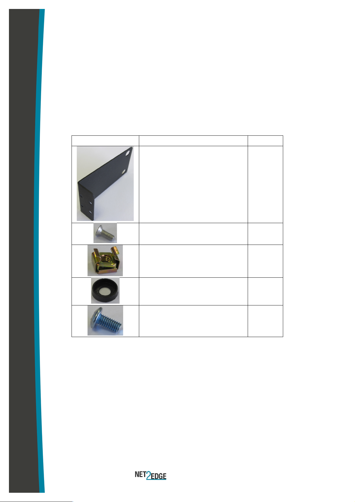
The Rack Mounting Kit comprises the following:
Picture
Description
Quantity
L-Bracket
2
Long Net2Edge case screw
4
Cage nut
4
Washer
4
Rack Mount screw
4
All Net2Edge products can be mounted in a standard 19" rack housing. To allow
products to be installed into a 19" rack, a Rack Mounting Kit must be purchased for the
product (s). There are a number of rack mounting options depending on the size of the
product ordered. The following guide will explain how to use the Rack Mounting Kit with
Net2Edge products:
1. Remove the four short screws near the front or rear panel on the left and right
hand sides of the DataBand ISU. The unit can be mounted with the front panel
facing forward or with the ports facing forward as required.
2. Fit one of the L-Brackets to the side of the unit. The four small fixing holes allow
the unit to protrude forward or sit further back depending on the desired position
Page 6
QSG | Quick Start Guide: DB-ISU
| www.net2edge.com
6
of the unit. The bracket may also face forwards or backwards depending on the
desired position of the unit.
3. Fix the L-Bracket in place using the Long Net2Edge case screws.
4. Fix the second L-Bracket to the other side of the case in the same way.
5. Put the Rack Mount screws through the Rack Mount washers.
6. Offer the unit up to the rack and fix it in place using the Rack Mount Screws and
Rack Mount cage nuts.
3.2 Standard Accessories
The following accessories are supplied with the DataBand ISU:
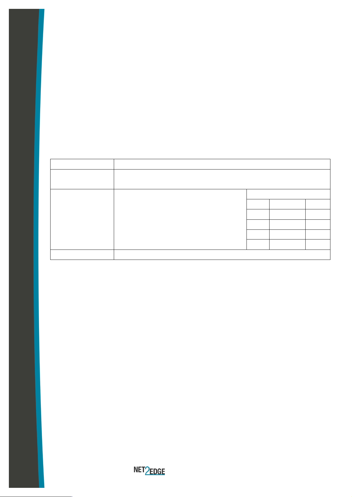
Item
Description
DbManager CD
Installable DbManager application, technical documents and
manuals
Controller Cable
Management cable. Connects to the
DataBand ISU’s Terminal port
Cable Spec
RJ12
DB9S
Pin
Function
Pin
1
Rx
3
2
Tx
2 3 Gnd
5
IEC Mains Cable
Connects DataBand ISU to the mains supply
3.3 Optional Accessories
The following items can be ordered separately:
ISDN Cables
Cables to connect the DataBand ISU to a CPE or network.
Please see the full manual for specifications of all Net2Edge
cables
Rack Mounting Kit
Enables the DataBand ISU to be mounted in a standard 19"
rack
3.4 Making Connections
First, connect the ISDN cables to DataBand ISU followed by the Terminal Port
management cable (if required).
If the unit has a DC power supply connection, use the screw terminals to connect the
DC power source.
Page 7

QSG | Quick Start Guide: DB-ISU
| www.net2edge.com
7
Warning: The -48VDC power terminals are marked 0V, -48V, and GND.
Net2Edge -48VDC products are designed for use with negative voltage DC
supplies, and therefore expect the positive voltage to be connected to the 0V
terminal, and the negative connected to -48V. Please be sure about the polarity
of this connection before connecting power to the terminals. Units which have a
positive +24VDC power source will be marked +24VDC, 0V and GND
respectively. Please ensure that the positive connection is made on the +24VDC
terminal.
3.5 Installing DbManager
DbManager is required in order to monitor and manage the DataBand ISU. Management
can be made using the Terminal (serial) port, or using TCP/IP over a LAN or WAN.
DbManager is installed using the CD provided with product or can be downloaded from
the Net2Edge Website: www.net2edge.com
1. Insert the DbManager Installation Disk into the drive of the PC which will be used
for management of DataBand ISU.
2. InstallShield Wizard will start up. Follow the steps to install DbManager.
3. Serial Number – Enter the Serial Number on the case of the DbManager Disk.
N.B.: DbManager is supplied as a 'Lite' version by default. This allows configuration
and monitoring of devices, but only allows configuration of a single device node and
a single user account. To use DbManager in 'Lite' mode, do not enter a serial
number during installation. Please see the full DbManager User Manual for more
information on configuring and using DbManager.
Warning: If an older version of DbManager is already installed on the management
PC, it is necessary to update to the version supplied on the new DbManager CD.
This can be done by consulting the ‘Upgrade’ folder on the DbManager CD. The
‘readme.txt’ file explains how to upgrade to the new DbManager without reinstalling
the program.
Page 8
QSG | Quick Start Guide: DB-ISU
| www.net2edge.com
8
4. Initial Configuration / Setup
Follow these steps to connect to DataBand ISU with DbManager and configure the unit
for use.
Configuration of DataBand ISU is carried out by setting up DbManager to make a
management connection, and then setting up the elements of DataBand ISU in this
order:
Terminal / LAN Port
The unit-specific settings of the DataBand ISU such
as the IP Address and Identifier
ISDN Ports
Each ISDN port can be individually configured with
the correct settings to interface with another device
or network. Here the bonding number for
conferences can also be stored
IMUX Ports
The Serial ports can be used to configure and
initiate calls. The Control Lead status of ports can
also be checked from here
4.1 Connecting to DataBand ISU
1. Start up the DbManager Application
2. Login as Super User (no password required)
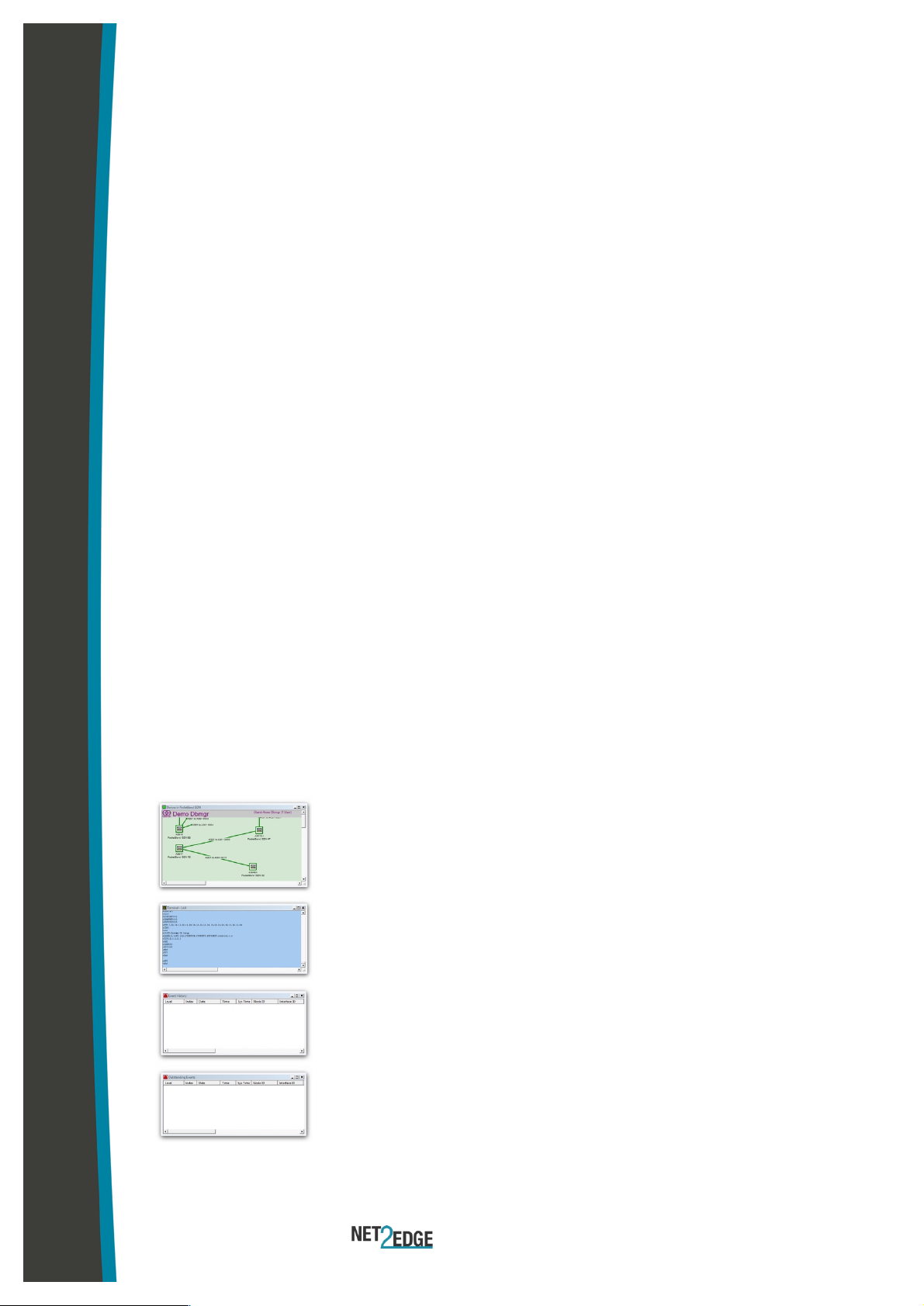
3. Four windows will be displayed:
Map
A network map showing Nodes
and Links between Net2Edge
devices
Terminal
A view of the communications
between DbManager and
DataBand ISU
Event History
All events which occur while
connected to DataBand ISU
Outstanding Events
Current Events
4. Select View Properties Terminal from the DbManager toolbar.
Page 9

QSG | Quick Start Guide: DB-ISU
| www.net2edge.com
9
5. 192.168.0.1 should already be configured. If using another IP address, add it
to the list using the Add button.
6. Click OK OK
7. Select the Devices in World window and double click the Device node
8. The Connected to Device window should appear, showing the front and rear
panels of DataBand ISU.
Info: TCP/IP management requires TCP port 3001 (dec) to be open between
the management PC and DataBand ISU. Any switches, hubs or routers must
be configured to allow communication on this port in order to manage
DataBand ISU via TCP/ IP
A successful management connection will open up the Connected to Device window:
4.2 Notes on configuring DataBand ISU
Uploading
Changes to the configuration can be made on each window and saved using the OK
key when exiting each window. When happy with the configuration, it must be uploaded
to the DataBand ISU for the new settings to come into effect.
To upload, go to File Upload and wait until the progress bar completes.
Saving Files
Configuration files can be saved in order to backup settings or copy settings across to
another unit. Once the configuration has been uploaded, go to File Save File and
choose a location where you wish to save the file. The file extension of any saved config
files is .dbc
Loading Files
Once connected to a unit, an existing configuration file can be loaded to the device. Go
to File Open File and navigate to the saved file. Click Open. Now the file must be
uploaded to DataBand ISU: Go to File Upload and wait until the progress bar
completes.
Warning: When loading existing configuration files to a unit, please ensure that
the correct configuration files are used for the unit type in use. DataBand ISU
configuration files are not compatible with other Net2Edge products.
Page 10

QSG | Quick Start Guide: DB-ISU
| www.net2edge.com
10
4.3 Device Settings
This menu controls unit-specific features of the DataBand ISU such as the IP Address,
Identifier, Serial Number, Configuration Number, Time & Date and Event Reporting.
These features are all fully explained in the DataBand ISU User Manual on the
DbManager Installation Disk.
4.4 PRI Ports
There are two LEDs for each PRI port, and the LED states are as follows:
Top LED on:
Layer 1 and 2 established
Top LED flashing:
Layer 1 established, trying to synchronize with Layer 2
Bottom LED on:
Calls active on interface
1. Click on an enabled PRI port.
2. The configuration settings for the port are displayed.
3. Configure the settings as required for the port.
4. Click OK to save the settings.
Note: The PRI port can be switched to NT mode (if the switchable PRI option is
taken). The setting must then be uploaded, DataBand ISU must be rebooted and
a crossover cable must be used in order to use the port in NT mode.
4.5 ISDN Numbers
The ISDN Numbers window can be used to define the Bonding Numbers which
DataBand ISU sends back to calling devices in order to set up conferences at speeds of
up to 1024kbps. The Bonding Numbers should be the DDI or MSN numbers of the local
ISDN line supplied by the carrier.
1. Click on the ISDN Numbers button on any ISDN port to access the number list.
2. Right-click in the empty window and select New to add a list of ISDN Numbers
3. Enter a number up to 24 digits long and click Save + Exit.
4. Extra options such as editing and deleting can be accessed by right-clicking
existing entries.
Note: If calls are to be received from international callers, please add the country
prefix e.g. 001 for USA. Numbers should be entered in digit form without any
special characters (*#+)
Page 11

QSG | Quick Start Guide: DB-ISU
| www.net2edge.com
11
4.6 BRI Ports
There are two LEDs for each BRI port, and the LED states are as follows:
Top LED on:
Calls active on B channel number 1
Bottom LED on:
Calls active on B channel number 2
LEDs off:
No calls active on interface
1. Click on an enabled BRI port.
2. The configuration settings for the port are displayed.
3. Configure the settings as required for the port
4. Click OK to save the settings.
Note: Each BRI port can be switched to NT mode (if the switchable BRI option is
taken). The setting must then be uploaded, DataBand ISU must be rebooted and
a crossover cable must be used in order to use the port in NT mode.
Numbers
The Numbers fields can be used to define the Bonding Numbers which DataBand ISU
sends back to calling devices in order to set up conferences at speeds of up to
1024kbps. The Bonding Numbers should be the DDI or MSN numbers of the local ISDN
line supplied by the carrier. Two numbers are configurable for each BRI port.
Enter two numbers, each up to 24 digits long in the Number fields.
Note: If calls are to be received from international callers, please add the country
prefix e.g. 001 for USA. Numbers should be entered in digit form without any
special characters (*#+)
4.7 Imux Ports
DataBand ISU can be fitted with single or dual Imux Ports. Each Imux port can have
numbers and ISDN ports assigned to it, so that incoming conferences are directed to
specific ports as they arrive. Click on an Imux Port to access the configuration options.
Incoming Number
Use the Drop-down menus to assign a specific ISDN number to the Imux port, or use
the default setting of All Ports and Numbers to allow any ISDN port and number
access. Any numbers configured on the BRI ports or PRI port will be shown in the list.
Page 12
QSG | Quick Start Guide: DB-ISU
| www.net2edge.com
12
Data Rate
Required and Minimum rates can be set for the Imux port. The Required rate is the
maximum data speed which can be accepted on the port, while the Minimum is the
lowest speed which will be accepted.
Stored Conferences
Please see the full DataBand ISU User Manual in order to configure stored conference
settings using the Phone Book option.
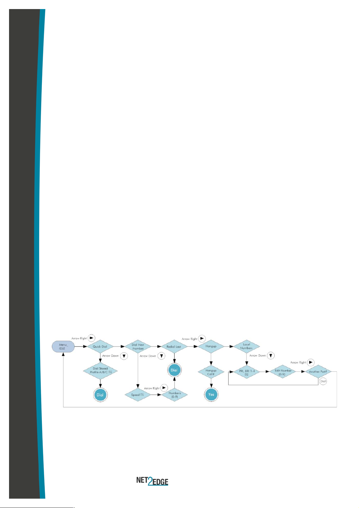
4.8 Front Panel
The front panel of DataBand ISU can be used to initiate a conference with a remote site
whose number and data rate settings have been pre-configured in the Phone Book, or
to instantly start a conference with another site using a new number and target data
rate.
Note: Dial and Hangup functions can also be carried out using a third party serial
device via the RS.366 port. Please contact Net2Edge for information.
0-9
Use to enter DDI number of a remote site
Menu
Return to main menu at any time
p
Del
Delete an existing number entry, or scroll up through a list
u
Scroll menu items
q
Enter Sub-menu and scroll down through menu items
Dial
Initiate a conference with a remote site
Yes
Confirm selection
4.9 Finishing Configuration
Note: Please remember to Upload when configuration of DataBand ISU is
complete. To upload, go to File Upload and wait until the progress bar
completes.
Page 13
QSG | Quick Start Guide: DB-ISU
| www.net2edge.com
13
4.10 Additional Resources
All Net2Edge products and the DbManager application have their own User Manuals
which can be found in the 'Documents & Manuals' folder on the DbManager installation
disk or by registering at the Net2Edge website: www.net2edge.com
For help with a specific problem, please click on the On-Line Help icon on the website,
or email a request to [email protected]
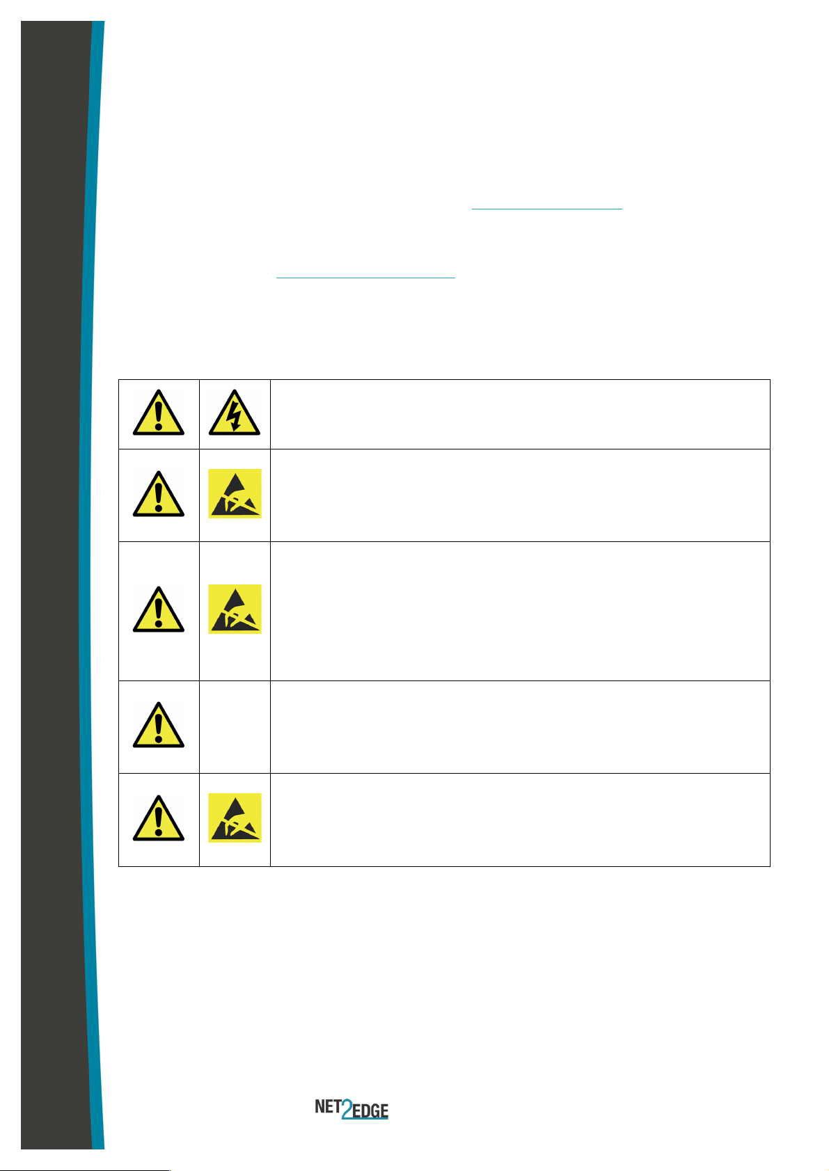
5. Safety Warnings
Caution: Danger of electric shock. The device may be
connected to mains voltages. Switch to power-off state before
working on the device.
Caution: Danger of electrostatic discharge. Electronic
components are sensitive to electrostatic discharges that might
damage the device. Protect the device from electrostatic
discharges by wearing an electrostatic wristband.
Caution: Interruption of data transmission. Data transmission
will be interrupted during any work on the transmission line
and/or deactivation of the power supply. Make sure that that any
work will only be carried out on inactive lines (without data
transmission) or during quiet times to reduce interference to live
systems.
Caution: Danger of damage to devices or service interruption.
Access by unauthorized third persons may cause damage to
devices and/or interrupt services. Make sure that sub-racks are
only installed in lockable locations.
Caution: Danger of overvoltage. During faults, dangerous
unprotected voltages may be present. Ensure sufficient
grounding of the housings, i.e. by connecting the grounding
contact.
• Safety requirements are not fulfilled unless this equipment is connected to a wall
socket outlet with a protective earth (PE) contact.
• The power cord used to connect this equipment must be HAR marked and fitted
with an IEC320 connector and an ASTA approved moulded plug.
• There are no user serviceable parts in this equipment. All servicing and repair
tasks must be undertaken by qualified service personnel.
• Isolation from mains power is achieved by the removal of the main power cord
Page 14

QSG | Quick Start Guide: DB-ISU
| www.net2edge.com
14
6. Contacts
Corporate Headquarters
Net2Edge Limited
Kulite House
BASINGSTOKE
Hampshire
RG24 8UG
United Kingdom
Tel: +44 345 013 0030
www.net2edge.com
 Loading...