

Page 1
2 Adults
Needed
www.net1netball.co.uk
If assistance is needed - do not contact the store! Call our customer services department on:
UK: 0115 985 3500
Hours: 9am to 5pm, Monday to Friday (except National Holidays).
GM Operations Centre,
Trent Lane, Colwick, Nottingham,
NG2 4DS United Kingdom
NET1 is a registered trade mark of Unicorn Products Ltd. © 2018
C9951
N123201
Page 2
WARNING
FAILURE TO FOLLOW THESE WARNINGS MAY RESULT
IN SERIOUS INJURY AND/OR PROPERTY DAMAGE
Owner must ensure that all players know and follow these rules
for safe operation of the system.
•
injuring others. Release the rim as soon as safely possible.
• During play, especially when performing dunk type activities,
keep players face away from the backboard, rim and net.
Serious injury could occur if teeth/face come in contact with
backboard, rim, or net.
• DO NOT slide, climb, or play on base or pole.
•
or the system will tip quickly causing serious personal injury.
• When adjusting height or moving system, keep hands and
• DO NOT allow children to move or adjust system.
• During play, do not wear jewellery (rings, watches, necklaces,
etc. Objects may entangle in net.
• Surface beneath the base must be smooth and free of gravel
or other objects. Punctures can cause leakage and could cause
system to tip over.
• Keep water and organic material away from pole. Pole can
rust and fall.
• Once a month check pole and all metal parts for rust.
Completely remove rust and repaint with exterior enamel. If
rust has penetrated any steel part, replace the part
immediately.
• Check system before each use for proper ballast, loose
hardware, instability, and signs of corrosion and repair before
each use. Never play on damaged equipment.
• DO NOT use system during windy or severe weather, system
may tip over. Place system in an area protected from the wind
or in an area away from property that may be damaged if the
system falls.
UK: +44 115 985 3500
Page 3
2 Adults
Needed
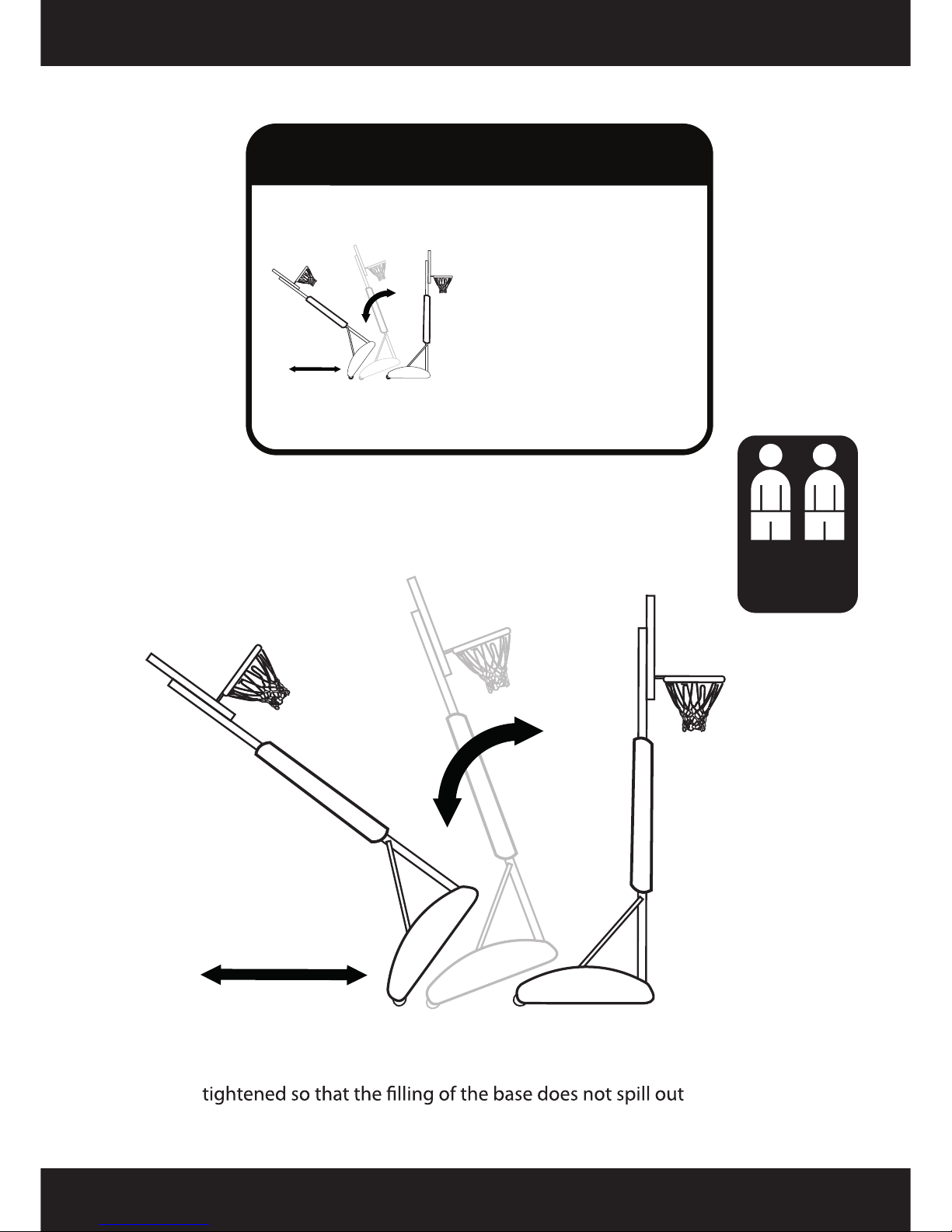
When moving the system take care to ensure the base cap is securely
Moving the system
If assistance is needed - do not contact the store! Call our customer services department:
UK : 0115 985 3500
MOVING SYSTEM
1) Carefully lower the system rearward
onto the wheels. Whilst holding the
system by the top pole.
2) Carefully move the system i
nto
place.
3) Position basketball system to
chosen location.
4) Carefully restore to upright
position.
Page 4
Page 5
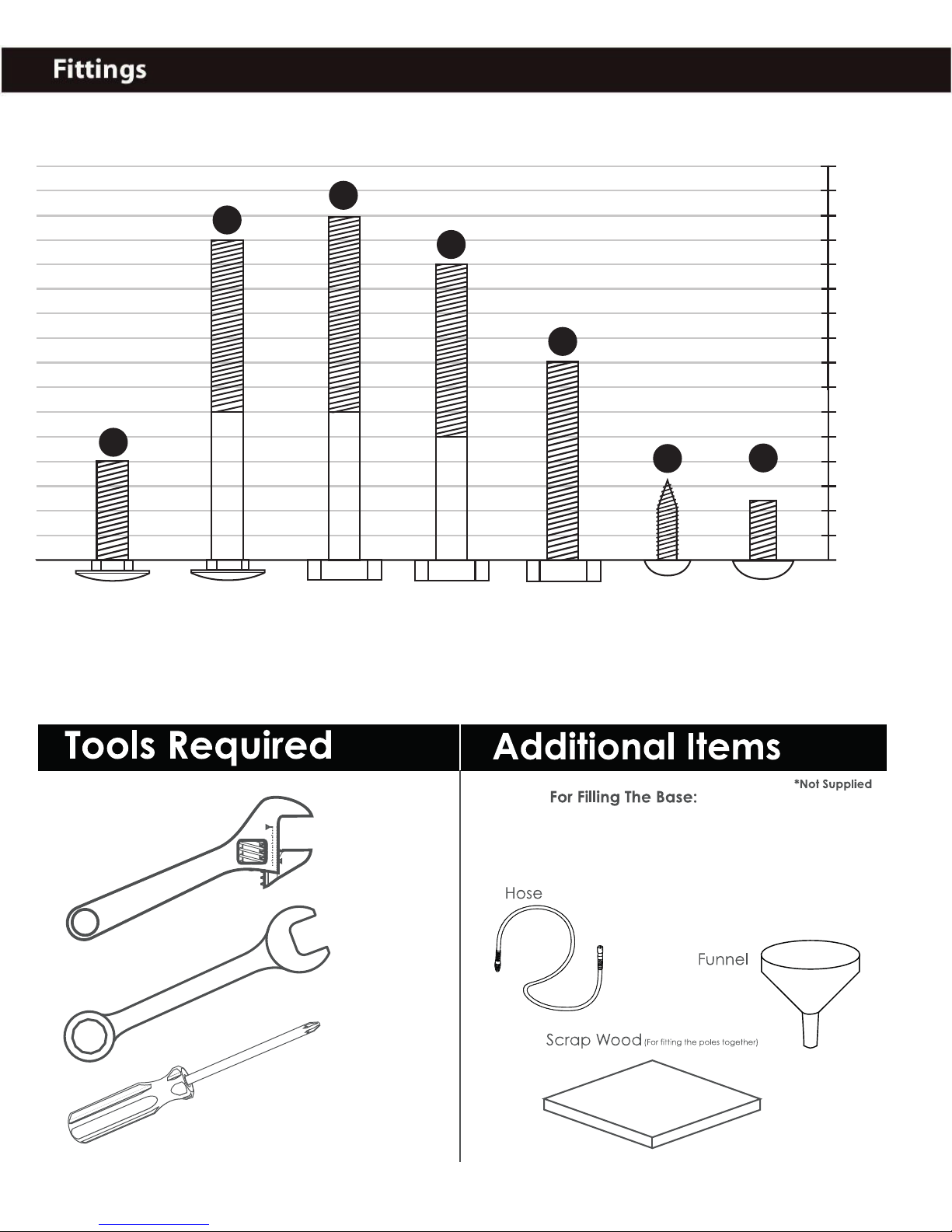
Base to be filled with either dry sand
or water
5mm
10mm
15mm
20mm
25mm
30mm
35mm
40mm
45mm
50mm
55mm
60mm
65mm
70mm
75mm
80mm
S
T
U
V
W
X
Y
2×
M8
20mm
1×
M8
65mm
3×
M8
70mm
1×
M8
60mm
1×
M8
40mm
2×
M5
16mm
12×
M5
12mm
Page 6
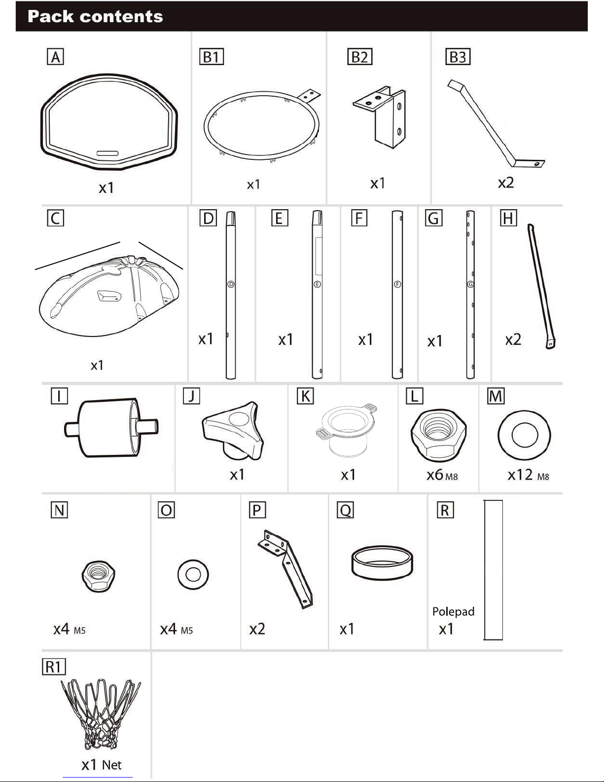
83cm 58cm
×2 Wheels
×2 Axles
Page 7
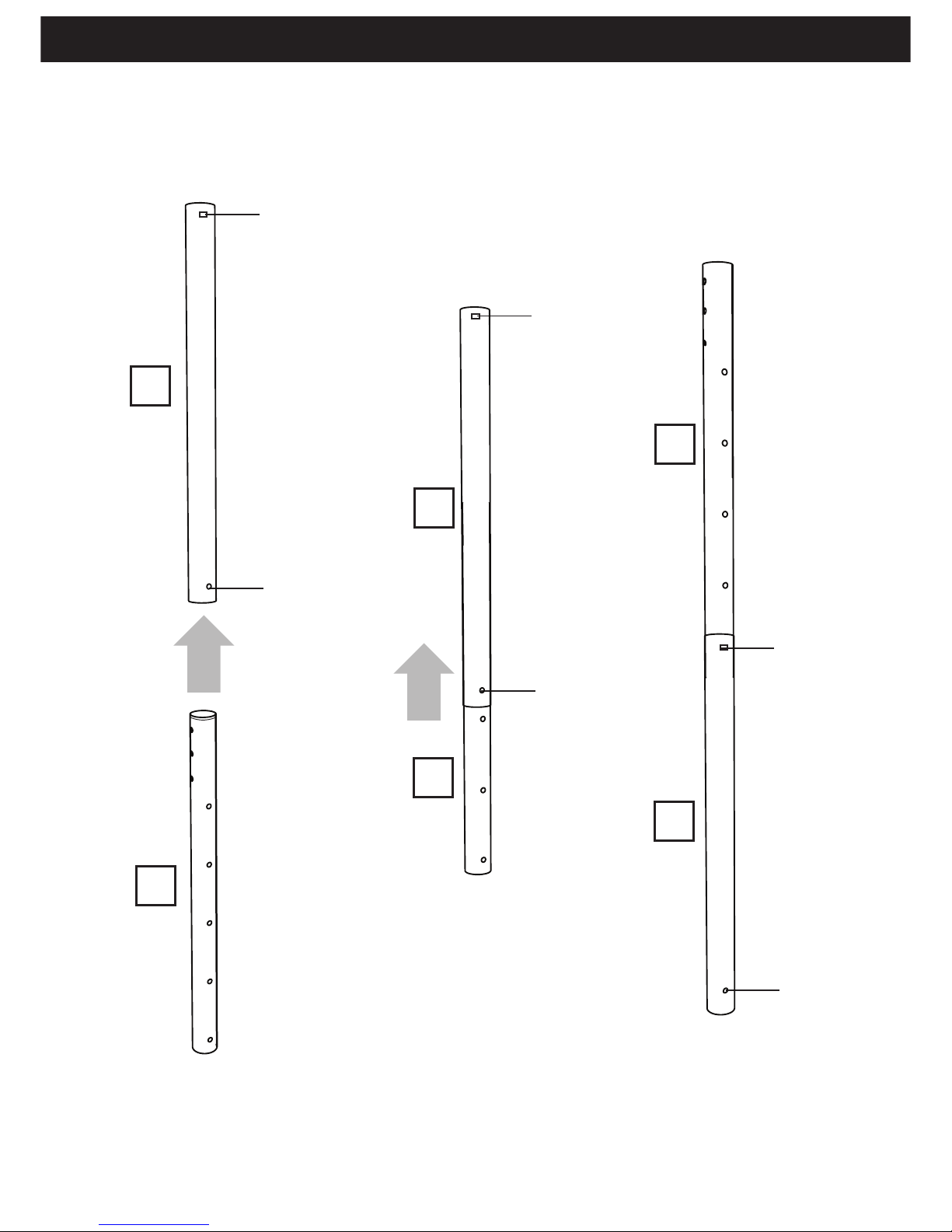
SQUARE SHAPE
HOLE
ROUND SHAPE
HOLE
ROUND SHAPE
HOLE
ROUND SHAPE
HOLE
SQUARE SHAPE
HOLE
SQUARE SHAPE
HOLE
IMPORTANT
BEFORE COMMENCING POLE ASSEMBLY
Insert the top pole (G) up inside the upper middle pole (F)
so that it protrudes from the top.
Top pole (G) has ten holes (ve each side) for the height adjustment, and
six holes
three each side) at the top for xing the backboard and goal supports.
G
F
F
G
G
F
The upper middle pole (F) has two square shaped holes opposite each other at
the top of the pole for tting the height adjustment bolt and another hole
towards the bottom of the pole for the location screw (C).
(
Page 8
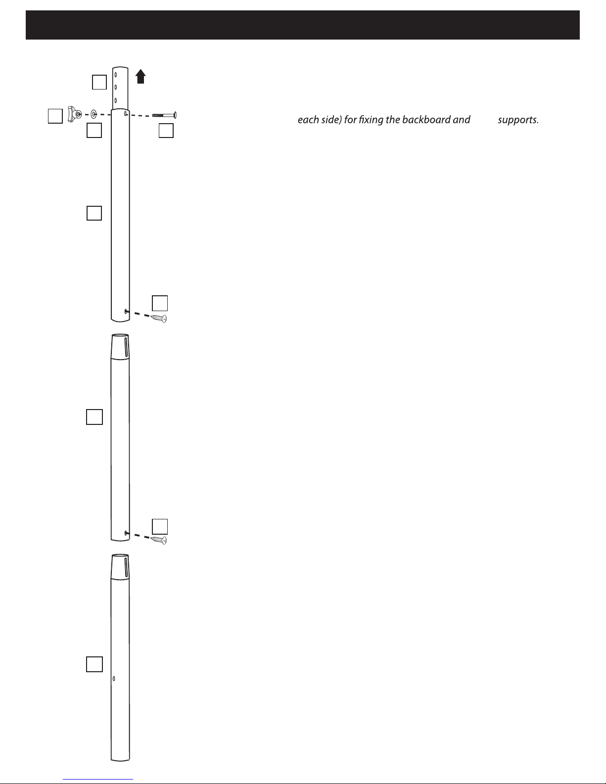
Step 1: Pole assembly
Pull the Top Pole (G) up through the Upper Middle Pole (F) far enough
to clear the holes near the bottom of the Upper Middle Pole (F).
Top pole (G) has ten holes (5 each side) for the height adjustment, and
six holes (t
hree
The upper middle pole (F) has two square shaped holes opposite each
other at the top of the pole for the height adjustment and two round
Position the Top Pole (G) at its lowest height setting and insert one
carriage bolt ( T ) into the square hole at the top of the Upper Middle
Pole (F) and through the Top Pole(G). Secure with washer (M)
Note: The Adjustment Knob (J) will face towards the rear of the
basketball system base.
Align the slot in the Lower Middle Pole (E) with the hole
in the Upper Middle Pole (F) and slide the Upper
Middle Pole (F) over the Lower Middle Pole (E).
The lower middle pole (E) has one slot at the top of the pole
and one hole near the bottom end.
Insert one Pole Joint Screw (X) through the small hole in
the Upper Middle Pole (F) and in to the Lower Middle
Pole (E).
Note: The Pole Joint Screw (X) will spin freely once
installed.
Align the slot in the Bottom Pole (D) with the hole in the
Lower Middle Pole (E) and slide the Lower Middle Pole
(E) over the Bottom Pole (D).
Base pole (D) has one slot at the top of the
pole, two holes in the middle and one nut inside
the bottom end.
Insert one Pole Joint Screw (X) through the small hole in
the Lower Middle Pole (E) and into the Bottom Pole (D).
Note: The Pole Joint Screw (X) will spin freely once
installed.
Do not jam the poles together until instructed.
T
G
F
M
J
X
X
E
D
goal
holes towards the bottom of the pole.
adjustment knob (J).
Page 9
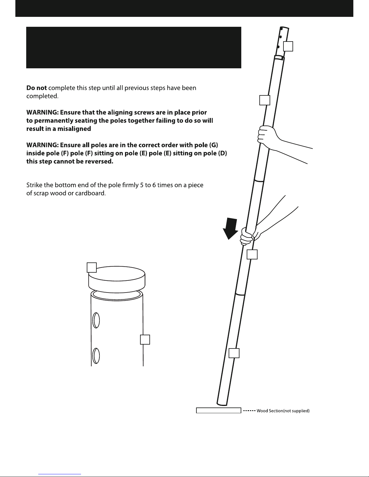
Step 2: Pole assembly
WARNING THIS STEP CANNOT BE REVERSED
The poles must be seated together by striking them on a section of the wood
ve to six times. Failure to seat the poles correctly could allow the poles to
separate during use, which could lead to serious personal injuries or property damage.
G
F
D
E
G
Q
goal.
Take care not to hit your feet with the pole sections, as
this could cause injury.
If not already attached, add pole cap (Q) to the top of pole (G).
Note: If the item is assembled incorrectly, charges will apply for
replacement parts. Please call 0115 985 3500 (UK)
for more information.
Page 10
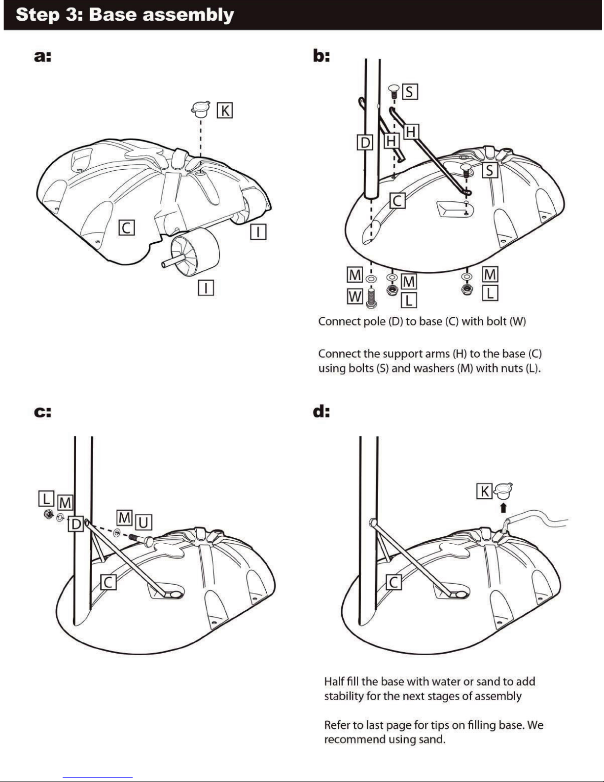
Connect the base wheels (I) to the base (C).
If not already tted, insert the base plug (K).
When lling the base with water or sand,
remove the plug, ll, and replace.
Connect the support arms (H) to the base pole (D)
using bolt (U) and washers (M) and nut (L).
Now tighten all bolts evenly taking care not to over
tighten.
.
Page 11
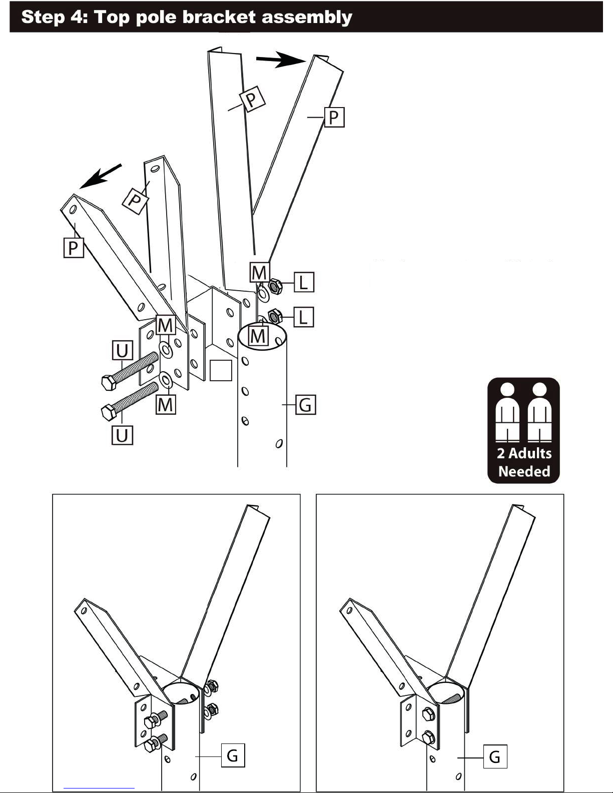
B2
Fix the support arms (P) to the bracket
(B2) and the top pole (G) using 2× M8
70mm bolts (U), 4× M8 washers (M)
and 2× nut (L).
Page 12
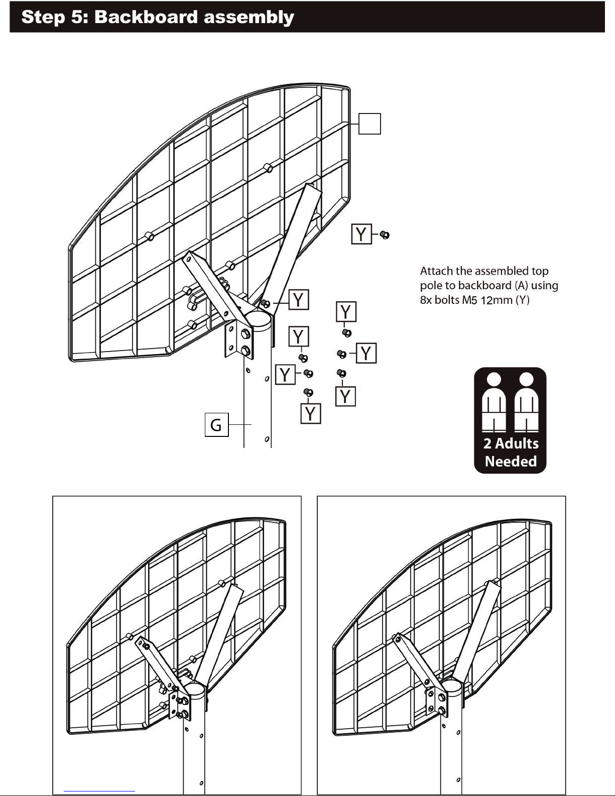
A
Page 13
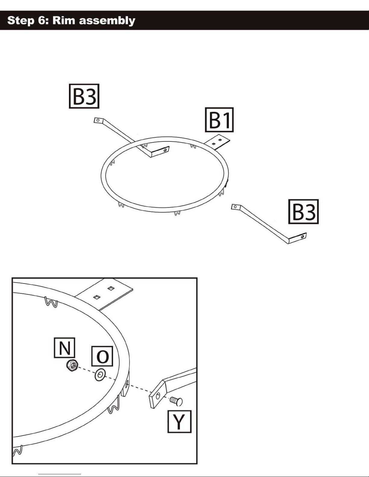
Align component goal arm support (B3) to
goal (B1). Secure using bolt (Y), washer (O)
and nut (N). Repeat for both sides.
Page 14
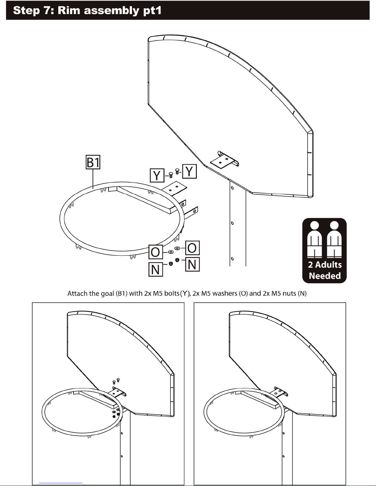
Page 15
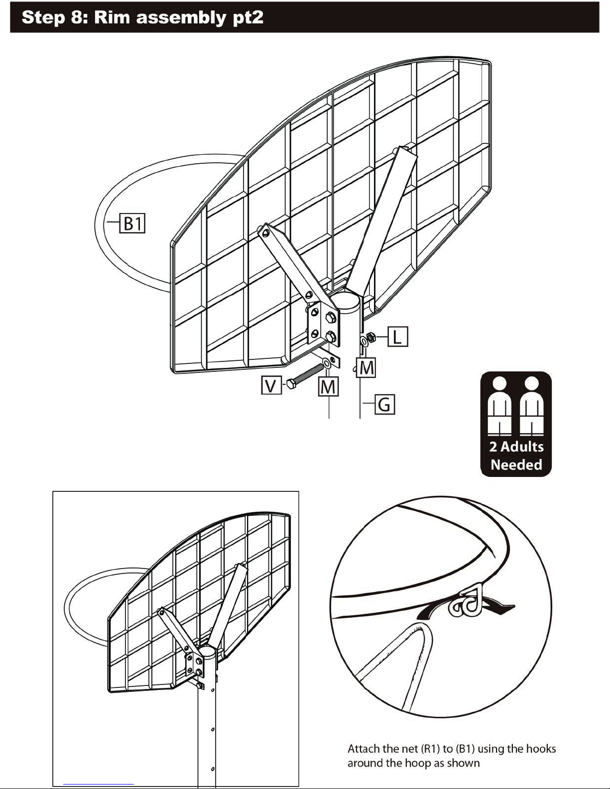
Attach the support arms of the goal (B1) to the top
pole (G) using bolt M8 60mm (V) washers M8 (M)
and nut M8 (L).
Page 16
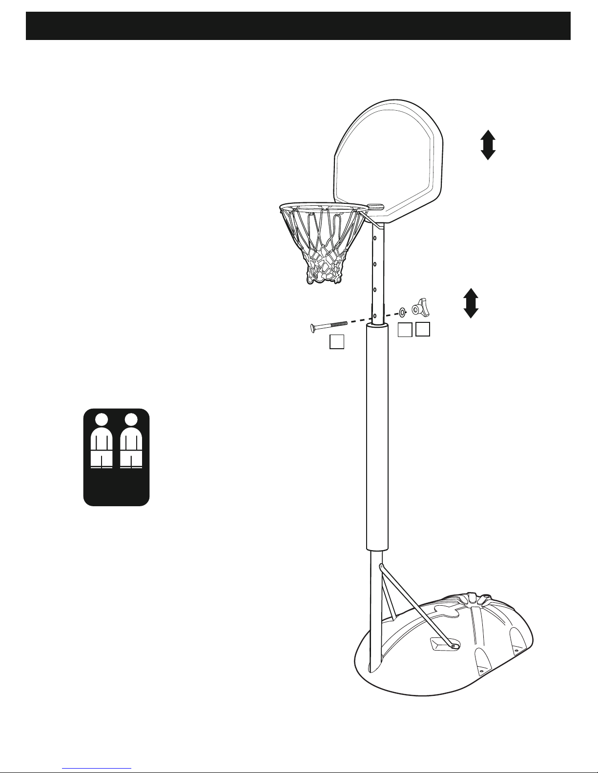
Step 9: Height Adjustment
To adjust the height, loosen nut ( J )
and remove washer (M) and bolt
( T ). Slide the top pole up or down
to the desired height, ensuring that
the holes in both poles align, and
reinsert bolt ( T ) with washer (M)
and tighten nut (L).
2 Adults
Needed
T
J
M
Page 17
and support
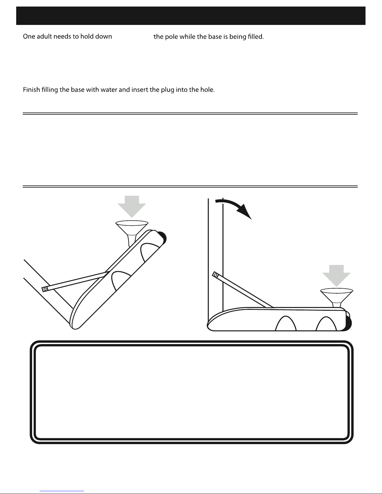
Filling the base (requires 2 adults)
FILLING WITH WATER:
Add water through the hole on the top of the base until the water is just below the hole.
FILLING WITH SAND:
Using a funnel, add sand through the hole in the top of the base until the sand is just below the hole.
(To avoid damage to the base, carefully position the system to the desired location using the wheels on the base)
Do not allow water in the base to freeze. During sub-freezing weather conditions.
add a small amount of non toxic anti-freeze to the water to prevent freezing.
(Using two adults, carefully stand the system upright)
Pivot the system on its wheels, taking care not to drag the base on the ground. Using two adults, carefully stand
the system upright. Finish lling the base with sand and insert the plug.
For safety reasons, we recommend that sand be used instead of water to ll the base. If
a leak develops, water could run out unnoticed, allowing the system to fall over, resulting in personal injuries or property damage. Check the base carefully for leaks. If a
leak is found, lay the system down on the ground and call Customer Services on 0115
985 3500 (UK) for assistance. Do not use, stand up, or play on a leaking system. When
lling, moving, or playing on the system, always make sure the base is on a smooth
surface free of stones or sharp objects that could puncture the base. If the system is to
be used indoors, the base must be lled with sand.
NET1 is a registered trade mark of Unicorn Products Ltd. © 2018 © 2018 Unicorn Products Ltd.
 Loading...