


Promina® Series
Multiservice Access Platform
Promina 800 Installation and
Maintenance

Part Number: 037037-405 Rev A
Copyright © 2009 Network Equipment Technologies, Inc. All rights reserved.
NETWORK EQUIPMENT TECHNOLOGIES, INC. (hereinafter referred to as "N.E.T."), PROVIDES THIS
DOCUMENT AS IS, WITHOUT WARRANTIES OF ANY KIND, EITHER EXPRESSED OR IMPLIED,
INCLUDING, BUT NOT LIMITED TO, THE IMPLIED WARRANTY OF MERCHANTABILITY AND FITNESS
FOR A PARTI C ULAR PURPOSE.
No part of this publication may be stored in a retrieval system, transmitted or reproduced in any way, including photocopy, photograph, magnetic, or other record, without the prior written permission of N.E.T. Unpublished-rights
reserved under the copyright laws of the United States.
Trademarks
The N.E.T. logo, PanaVue, PrimeSwitch, Promina, SCREAM, Service Creation Manager, and SHOUTIP are
registered trademarks, and CellXpress, FrameXpress, Frame Relay Exchange, IPNX, LAN/WAN Exchange, Network
Equipment Technologies, N.E.T., the net.com logo, net.com, netMS, PortExtender, PrimeVoice, SCREAMvue, and
SHOUT are trademarks of Network Equipment Technologies, Inc.
SunOS and Solaris software copyright is held by Sun Microsystems, Inc. Sun Microsystems is a registered trademark
and Sun, SunOS, OpenWindows, Solaris, and Ultra are trademarks of Sun Microsystems, Inc. UNIX is a registered
trademark of The Open Group.
All other trademarks and registered trademarks are the sole property of their respective owners.
This document constitutes the sole Specifications referred to in N.E.T.'s Product W arranty for the products or services
described herein. N.E.T.’s Product Warranty is subject to all the conditions, restrictions, and limitations contained
herein and in the applicable contract. N.E.T. has made reasonable efforts to verify that the information in this document is accurate, but N.E.T. reserves the right to correct typographical errors or technical inaccuracies. N.E.T.
assumes no responsibility for any use of the information contained in this document or for any infringement of patents or other rights of third parties that may result from the use of this document. Networking products cannot be
tested in all possible uses, configurations or implementations, and interoperability with other products cannot be
guaranteed. The customer is solely responsible for verifying the suitability of N.E.T.'s products for use in its network.
Local market variations may apply. This document is subject to change by N.E.T. without notice as additional information is incorporated by N.E.T. or as changes are made by N.E.T. to hardware or software.
U.S. Government Rights, Government Use rs
The software accompanying this documentation is furnished under a license and may only be used in accordance with
the terms of such license. This documentation is "commercial computer software documentation" as that term is used
in 48 CFR 12.212. Unless otherwise agreed, use, duplication, or disclosure of this documentation and any related
software by U.S. Government civilian agencies is subject to restrictions as set forth in 48 CFR 52.227-14 (ALT III)
and 48 CFR 52.227-19, and use, duplication, or disclosure by the U.S. Department of Defense is subject to restrictions as set forth in 48 CFR 227.7202-1(a) and 48 CFR 227.7202-3(a) or, if applicable, 48 CFR 252.2277013(c)(1)(ii) (OCT 1988).
Released
November 2009
Network Equipment Technologies, Inc.
6900 Paseo Padre Parkway
Fremont, CA 94555 U.S.A.
http://www.net.com
ii Promina 800 Installation and Maintenance

Contents
. . . . . . . . . . . . . . . . . . . . . . . . . . . . . . . . . . . . . . . . . . . . . . . . . . . . . .
Promina® Series ............................................................................................................................ i
Preface.......................................................................................................................................... xiii
Document Conventions ...............................................................................................................iii-xv
Technical Assistance Information ...........................................................................................iii-xviii
Chapter 1 Promina Systems Overview
The Promina Network .................................................................................................................... 1-2
Private Networks ...................................................................................................................... 1-3
Interface and Device Compatibility ......................................................................................... 1-4
Hardware Features ......................................................................................................................... 1-5
Physical Interfaces ................................................................................................................... 1-5
Call Configuration .........................................................................................................................1-5
Network Management .................................................................................................................... 1-6
Chapter 2 Standard Equipment Modules
Overview ........................................................................................................................................ 2-2
Promina Controller Modules Overview ................................................................................... 2-3
Promina 800 Standard Equipment Configuration .......................................................................... 2-4
Standard and Expansion Shelves ....................................................................................... 2-5
High-Speed Shelf (HSS) .................................................................................................... 2-5
SX-2 Port-to-Shelf Configuration ...................................................................................... 2-5
Promina Standard Equipment Connectivity .................................................................................. 2-6
Promina 800 Node Standard Equipment Redundancy .................................................................. 2-7
Domain and System Redundancy ............................................................................................ 2-7
Nonredundant Configurations .................................................................................................. 2-8
Timing Sources ............................................................................................................................ 2-10
Chapter 3 Card Descriptions
Promina 800 standard Equipment Modules ................................................................................... 3-2
PPM Module ............................................................................................................................ 3-2
Master and Coprocessor Functions .................................................................................... 3-3
PPM Front Panel ................................................................................................................3-3
PPMI Card ...............................................................................................................................3-5
SX-2 Module ............................................................................................................................ 3-6
Promina 800 Installation and Maintenance Promina Series iii

. . . . . . . . . . . . . . . . . . . . . . . . . . . . . . . . . . . . . . . . . . . . . . . . . . . . . .
SX-2 Front Panel ...............................................................................................................3-6
SXI-2 Card ............................................................................................................................... 3-8
SXI-2 Connectors .............................................................................................................. 3-8
SBI Card ................................................................................................................................ 3-10
BX Front Panel ......................................................................................................................3-10
BXI Connectors .....................................................................................................................3-12
Promina Server Module ......................................................................................................... 3-13
PSM Redundancy ............................................................................................................ 3-13
PSM Front Panel .............................................................................................................. 3-14
Promina Server Module Interface .......................................................................................... 3-16
Bus Terminator ...................................................................................................................... 3-18
Dial-in Access Modem ................................................................................................................3-19
Chapter 4 Software Configuration
Card Installation ............................................................................................................................. 4-2
Card Installation After Node Initialization .............................................................................. 4-2
Standard Equipment Parameters .................................................................................................... 4-6
Processor Card Parameters ......................................................................................................4-6
[0] Alarm/Monitor Interface .............................................................................................. 4-6
[5] PPP on Aux Port ........................................................................................................... 4-6
[6] PPP Baud Rate ............................................................................................................. 4-7
[7] PPP Local IP ................................................................................................................ 4-7
[8] PPP Remote IP ............................................................................................................. 4-7
[9] PPP TyCo Device ......................................................................................................... 4-7
[10] MTU Size ................................................................................................................... 4-7
PSM Card Parameters .............................................................................................................. 4-7
[0/1] Console/Auxiliary Baud Rate ...................................................................................4-7
[2] External IP .................................................................................................................... 4-8
[4] Subnet Mask ................................................................................................................. 4-8
[5/6] PSM1/2 Assigned CardID ......................................................................................... 4-8
[10] PPP on Aux Port ......................................................................................................... 4-8
[11] PPP Baud Rate ........................................................................................................... 4-9
[12] PPP Local IP ..............................................................................................................4-9
[13] PPP Remote IP ........................................................................................................... 4-9
[14] PPP TyCo Device ....................................................................................................... 4-9
iv Promina Series Promina 800 Installation and Maintenance

. . . . . . . . . . . . . . . . . . . . . . . . . . . . . . . . . . . . . . . . . . . . . . . . . . . . .
[15] MTU Size ................................................................................................................... 4-9
Card Query Displays .................................................................................................................... 4-10
Processor Card Configurations .............................................................................................. 4-10
Card Configuration Descriptions ........................................................................................... 4-12
Alarm Panel I/F ................................................................................................................4-12
Auxiliary Port Configuration ........................................................................................... 4-12
Bytes of RAM Left .......................................................................................................... 4-12
CBUS Interrupts/Sec ........................................................................................................ 4-12
Code Version ...................................................................................................................4-12
Console Port Configuration ............................................................................................. 4-12
CPU Restart Count ........................................................................................................... 4-13
CPU Status ....................................................................................................................... 4-13
Current GMT ...................................................................................................................4-13
DB Checksum .................................................................................................................. 4-13
DB Status ......................................................................................................................... 4-13
External IP .......................................................................................................................4-14
Gateway IP Addr ............................................................................................................. 4-14
HW Revision ....................................................................................................................4-14
HW Serial No ...................................................................................................................4-14
Idle Time (%) ................................................................................................................... 4-14
Internal IP (Address) ........................................................................................................ 4-14
Internal IP Addr ...............................................................................................................4-14
Load Units ........................................................................................................................ 4-14
Local IP ............................................................................................................................ 4-14
MAC Addr .......................................................................................................................4-15
Master CPU ...................................................................................................................... 4-15
MTU Size ......................................................................................................................... 4-15
Number of Installed SSC Ports ........................................................................................ 4-15
Perm Boot Version ........................................................................................................... 4-15
Power Up .........................................................................................................................4-15
PPP Baud Rate ................................................................................................................. 4-15
PSM Card ID ................................................................................................................... 4-15
Remote IP ........................................................................................................................ 4-15
Restart .............................................................................................................................. 4-16
RTC Overruns .................................................................................................................. 4-16
Promina 800 Installation and Maintenance Promina Series v

. . . . . . . . . . . . . . . . . . . . . . . . . . . . . . . . . . . . . . . . . . . . . . . . . . . . . .
Serial Number ..................................................................................................................4-16
Slot Type .......................................................................................................................... 4-16
Status ................................................................................................................................ 4-16
Subnet Mask ....................................................................................................................4-16
Task Distribution ............................................................................................................. 4-16
Task Restart Count ........................................................................................................... 4-17
TyCo Device ....................................................................................................................4-17
Wrt Boot Version ............................................................................................................. 4 -17
Query PSM Displays ................................................................................................................... 4-18
PSM Card Configuration Descriptions .................................................................................. 4-19
Database ........................................................................................................................... 4-19
Ext IP Addr ...................................................................................................................... 4-19
Int IP Addr ....................................................................................................................... 4-19
PSM Code ........................................................................................................................ 4-19
MAC Addr .......................................................................................................................4-19
Status ................................................................................................................................ 4-19
SX-2 Card Configuration ............................................................................................................. 4-20
Active Domain ................................................................................................................. 4-20
DB Status ......................................................................................................................... 4-20
Domain ............................................................................................................................. 4-20
Firmware Revision ........................................................................................................... 4-21
Redundant SX .................................................................................................................. 4-21
Serial Number ..................................................................................................................4-21
Slot Type .......................................................................................................................... 4-21
Status ................................................................................................................................ 4-21
System Components ........................................................................................................ 4-21
BX Card Configuration ................................................................................................................ 4-22
Active Domain ................................................................................................................. 4-22
DB Status ......................................................................................................................... 4-22
Domain ............................................................................................................................. 4-22
Serial Number ..................................................................................................................4-22
Slot Type .......................................................................................................................... 4-22
Status ................................................................................................................................ 4-23
Redundant BX .................................................................................................................. 4-23
SX-2 Port .........................................................................................................................4-23
vi Promina Series Promina 800 Installation and Maintenance

. . . . . . . . . . . . . . . . . . . . . . . . . . . . . . . . . . . . . . . . . . . . . . . . . . . . .
Console Port Settings ................................................................................................................... 4-24
Chapter 5 SSC, HTC, and SCLP Ports
SSC Ports on the PPM, PLM, and IPLM ....................................................................................... 5-1
TBus Allocation ....................................................................................................................... 5-2
HTC Ports and SNMP Manageability ........................................................................................... 5-4
SSC Port Installation ..................................................................................................................... 5-5
SSC Port Parameters ................................................................................................................ 5-7
[0] Orig/Ans Mode ............................................................................................................. 5-8
[1] Destination Port ............................................................................................................ 5-8
[2] Call/Preempt Priority ................................................................................................... 5-8
[3] Secondary Call/Preempt Priority .................................................................................. 5-9
[4] Port Type ...................................................................................................................... 5-9
[5] Port Speed ....................................................................................................................5-9
[7] Routing Options ........................................................................................................... 5-9
[8] Primary Selected Path ................................................................................................ 5-10
[10] Selected Path Required ............................................................................................ 5-10
[11] IP Only ..................................................................................................................... 5-10
[14] Max Link Cost ......................................................................................................... 5-11
[15] Secondary Selected Path .......................................................................................... 5-11
[16] Primary Selected Gateway ....................................................................................... 5-11
[17] Secondary Selected Gateway ................................................................................... 5-11
[18] Gateway Required .................................................................................................... 5-11
HTC Port Installation ................................................................................................................... 5-12
HTC Port Parameters ............................................................................................................. 5-15
[0] Orig/Ans Mode ........................................................................................................... 5-16
[1] Destination Port .......................................................................................................... 5-16
[2] Call/Preempt Priority ................................................................................................. 5-16
[3] Secondary Call/Preempt Priority ................................................................................ 5-16
[4] Port Type .................................................................................................................... 5-16
[5] Port Speed ..................................................................................................................5-17
[7] Routing Options ......................................................................................................... 5-17
[8] Selected Path ..............................................................................................................5-17
[10] Selected Path Required ............................................................................................ 5-17
[12] IP .............................................................................................................................. 5-17
Promina 800 Installation and Maintenance Promina Series vii

. . . . . . . . . . . . . . . . . . . . . . . . . . . . . . . . . . . . . . . . . . . . . . . . . . . . . .
[13] Master-only .............................................................................................................. 5-18
SCLP/SSC Port Query Displays .................................................................................................. 5-19
PPM, PLM,
and IPLM Configurations ...................................................................................................... 5-19
Port Configuration Descriptions ............................................................................................ 5-20
ATM Routing ................................................................................................................... 5-20
Call Priority ...................................................................................................................... 5-20
Call State .......................................................................................................................... 5-20
Card Status ....................................................................................................................... 5-21
Card Type ........................................................................................................................ 5-21
Destination Port ...............................................................................................................5-21
Encry Routing ..................................................................................................................5-21
Fiber Routing ................................................................................................................... 5-21
GW Required ................................................................................................................... 5-21
Installed Port .................................................................................................................... 5-21
Last Disconnect ................................................................................................................5-21
Link Status ....................................................................................................................... 5-22
Orig/Ans Mode ................................................................................................................ 5-22
Pkts Recvd .......................................................................................................................5-22
Pkts Sent .......................................................................................................................... 5-22
Port Speed ........................................................................................................................ 5-22
Port Status ........................................................................................................................ 5-23
Port Type .......................................................................................................................... 5-23
Preempt Prty .................................................................................................................... 5-23
Pri Sel GW ....................................................................................................................... 5-23
Pri Sel Path ....................................................................................................................... 5-23
SCLX Routing ................................................................................................................. 5-23
Sec Call Priority ............................................................................................................... 5-23
Sec Prmt Priority ..............................................................................................................5-23
Sec Sel GW ...................................................................................................................... 5-23
Sec Sel Path ..................................................................................................................... 5-23
Terr Routing ..................................................................................................................... 5-24
HTC Port Query Displays ............................................................................................................ 5-25
Chapter 6 Promina 800 System
Promina 800 Configurations .......................................................................................................... 6-2
viii Promina Series Promina 800 Installation and Maintenance

. . . . . . . . . . . . . . . . . . . . . . . . . . . . . . . . . . . . . . . . . . . . . . . . . . . . .
STS Shelf ................................................................................................................................. 6-2
EXS Shelf ................................................................................................................................ 6-2
System Hardware ........................................................................................................................... 6-3
Configuration Specifications ......................................................................................................... 6-4
Load Units ................................................................................................................................ 6-4
Logical Slots ............................................................................................................................6-5
Module Power Consumption ................................................................................................... 6-5
Electrical and Environmental Specifications ........................................................................... 6-6
Physical Dimensions ...................................................................................................................... 6-7
Rack-mount System ................................................................................................................. 6-9
Cabinet-
mounted Systems ..................................................................................................................... 6-9
Cabinet Grounding ........................................................................................................... 6-14
Promina 800 Shelves ................................................................................................................... 6-15
Shelf Configurations .............................................................................................................. 6-15
Optional Cabinet Equipment ................................................................................................. 6-15
Shelf and Slot Numbering ...................................................................................................... 6-16
Slot Restrictions ............................................................................................................... 6-17
HSS-2 Shelf ...........................................................................................................................6-18
HSS-2 Shelf Door ............................................................................................................ 6-18
HSS-2 Backplane ............................................................................................................. 6-19
STS Shelf ............................................................................................................................... 6-22
STS Shelf Front Panel ...................................................................................................... 6-22
STS Backplane ................................................................................................................. 6-25
Setting the STS Backplane Jumper .................................................................................. 6-26
EXS Shelf .............................................................................................................................. 6-27
EXS Backplane ................................................................................................................ 6-27
Setting the EXS Backplane Jumper ................................................................................. 6-28
Power Supplies ............................................................................................................................ 6-29
System Power and BTU Output ............................................................................................. 6-29
Power Distribution Units ............................................................................................................. 6-30
Cabinet/Rack Mounted PDUs ................................................................................................ 6-30
-48 and -60 V DC PDU .................................................................................................... 6-30
Connection to DC Power Source ..................................................................................... 6-35
100 to 240 V AC PDU ..................................................................................................... 6-38
HSS-2 PDUs .......................................................................................................................... 6-42
Promina 800 Installation and Maintenance Promina Series ix

. . . . . . . . . . . . . . . . . . . . . . . . . . . . . . . . . . . . . . . . . . . . . . . . . . . . . .
-48 and -60 V DC PDU (dual feed) ................................................................................. 6-42
100 to 240 V AC PDU (Dual Feed) ................................................................................. 6-43
STS PDUs .............................................................................................................................. 6-44
-48 and -60 V DC Single/Dual Feed PDU ....................................................................... 6-44
Connection to DC Power Source ..................................................................................... 6-46
100 to 240 V AC PDU ..................................................................................................... 6-49
Fan Tray Assemblies ................................................................................................................... 6-50
Alarm Panel/Auxiliary Fan Assembly ................................................................................... 6-50
Jackfield Fan Assembly .........................................................................................................6-51
Intake Fan Assembly ............................................................................................................. 6-51
Thermostatic Controlled Fan Assembly ................................................................................ 6-52
Standard Equipment Modules ...................................................................................................... 6-53
HSS-2 Shelf Modules ............................................................................................................6-54
Reserved Card Slots ............................................................................................................... 6-55
System Redundancy ............................................................................................................... 6-56
Promina Processor Module .............................................................................................. 6-57
Promina Server Module ................................................................................................... 6-58
STS Shelf Modules ................................................................................................................ 6-58
STS Feature Modules ....................................................................................................... 6-59
EXS Shelf Modules ............................................................................................................... 6-60
Chapter 7 Promina System Components
Power Supplies .............................................................................................................................. 7-2
250 W Power Supplies ............................................................................................................. 7-2
Maximum Output Currents ................................................................................................ 7-5
Power Supply Specifications ............................................................................................. 7-5
400 W Power Supplies ............................................................................................................. 7-5
Maximum Output Currents ................................................................................................ 7-9
Power Supply Specifications ............................................................................................. 7-9
Aux Power Supply Tray .............................................................................................................. 7-10
Fan Trays ...............................................................................................................................7-11
Wattage and BTU Output ............................................................................................................ 7-12
Module Power Consumption .......................................................................................................7-13
Load Units .................................................................................................................................... 7-14
Logical Slots ................................................................................................................................ 7-15
x Promina Series Promina 800 Installation and Maintenance

. . . . . . . . . . . . . . . . . . . . . . . . . . . . . . . . . . . . . . . . . . . . . . . . . . . . .
Minimum Load Board ................................................................................................................. 7-16
System Load Current Requirements ...................................................................................... 7-17
Configuration Requirements .................................................................................................. 7-18
Bus Cards ............................................................................................................................... 7-18
T1 Jackfield .................................................................................................................................. 7-19
Alarm Panel Assembly ................................................................................................................7-20
Front Alarm Panel-2 ....................................................................................................................7-21
Alarm Panel-2 Connections ................................................................................................... 7-21
Rear Alarm Connectors ................................................................................................... 7-22
Serial Port Interface ..................................................................................................................... 7-23
Cross Connects ...................................................................................................................... 7-24
Baud Rates ............................................................................................................................. 7-24
Serial Port Pinouts ................................................................................................................. 7-24
Determining Bandwidth ............................................................................................................... 7-27
Transparent Signaling Overhead ........................................................................................... 7-27
Trunk Asynchronous Bandwidth ........................................................................................... 7-27
Pass-Through Timing ............................................................................................................7-27
Synchronous Timing .............................................................................................................. 7-27
Chapter 8 Operator Interface Commands
Expert Mode Command Summary ................................................................................................ 8-2
Appendix A Card Installation
Module Installation Requirements ................................................................................................ A-2
Load Units ............................................................................................................................... A-2
Logical Slots ........................................................................................................................... A-2
Promina 800 Card Installation ...................................................................................................... A-3
Interface Card Installation ............................................................................................................ A-5
Installing an Interface Card in an HSS-2 ................................................................................ A-5
Installing an Interface Card in an STS or an EXS .................................................................. A-5
Rear Interface Card Replacement ................................................................................................. A-9
Front Card Installation ................................................................................................................ A-10
Front Card Replacement ............................................................................................................. A-12
Connecting Interface Cards .................................................................................................. A-13
Installing Front Cards ........................................................................................................... A-13
Replacing Front Cards ..........................................................................................................A-13
Promina 800 Installation and Maintenance Promina Series xi

. . . . . . . . . . . . . . . . . . . . . . . . . . . . . . . . . . . . . . . . . . . . . . . . . . . . . .
Appendix B PanaVue Configuration for HTC Port Use
Typical Ethernet-Based Configuration ..........................................................................................B-2
HTC Configuration ..................................................................................................................B-3
Index..................................................................................................................................................1
xii Promina Series Promina 800 Installation and Maintenance

Preface
. . . . . . . . . . . . . . . . . . . . . . . . . . . . . . . . . . . . . . . . . . . . . . . . . . . . . .
About This Document
This document is for use in the installation and management of Promina
Series nodes. It provides information about standard equipment modules
and how to install standard equipment cards in the configuration
database.
Before using this document the reader should have a working knowledge
of data communications, and basic trunking and transmission concepts.
The user also needs to be aware of the hazards associated with electronic
equipment and electricity, a detailed discussion of which is beyond the
scope of this document.
This document provides screen displays as examples of output from the
Operator Interface. Because the displayed information is dependent on
each node’s configuration, the examples may not correspond exactly to
the information displayed by another node. Differences in software
releases can also account for differences in displayed information.
Document Organization
The document contains the following sections:
Section Title Description
Chapter 1 Promina Systems
Overview
Chapter 2 Standard Equipment
Modules
Chapter 3 Card Descriptions Describes the standard equipment modules
Chapter 4 Software Configuration Describes installing standard equipment cards
Chapter 5 SSC, HTC, and SCLP
Ports
Provides an overview of the Promina systems.
Provides basic information about the standard
equipment modules in Promina 800
and includes illustrations of the front panel
and rear cards with information on front panel
components and rear card ports.
in the configuration database through the
Operator Interface and includes descriptions
of card and port parameters.
Describes operation and usage of SSC
(Secondary Signaling Channel), HTC (HDLC
TBus Channel), and SCLP (Signaling Channel
Link Protocol) ports, used to communicate
network management information, control
signals and system updates between
domains.
Promina 800 Installation and Maintenance Promina Series xiii

Preface
. . . . . . . . . . . . . . . . . . . . . . . . . . . . . . . . . . . . . . . . . . . . . . . . . . . . . .
Section Title Description
Chapter 6 Promina 800 System Describes the hardware configurations an d
specification for the rack- and
cabinet-mounted Promina 800 systems.
Chapter 7 Promina System
Components
Chapter 8 Operator Interface
Commands
Appendix A Card Installation Installation and replacement procedures for
Appendix B PanaVue Configuration
for HTC Port Use
Describes Promina 800 Hardware
components.
Contains the Operator Interface commands
used for the configuration of modules.
CE cards in the Promina 800 systems.
Describes how to configure a PanaView
workstation for IP connectivity to a promina
network.
xiv Promina Series Promina 800 Installation and Maintenance

. . . . . . . . . . . . . . . . . . . . . . . . . . . . . . . . . . . . . . . . . . . . . . . . . . . . . .
Preface
Document Conventions
The following conventions are used in this document:
Convention Example Description
Key name Press DELETE. Refers to non-printing keys on the
keyboard that you press.
Simultaneous
Key
bold Caution: Used for emphasis.
bold courier Type exit Indicates a command to be typed.
Enter Enter add ndp 2 Indicates that after typing the information,
Italic Use breakers rated for
Screen shot YYYY/MM/DD Refers to date used in screen shot.
Module module The term module refers to card systems,
Press Shift+F1. Refers to non-printing keys on the
keyboard that need to be pressed
simultaneously.
press the Return or Enter key.
Refers to a new term that is defined in the
fast trip on supply
circuits.
For more information,
see the Hardware
Description manual.
text or glossary.
Refers to a document or book title.
except where the word card is used as
part of the name for the module.
Promina 800 Installation and Maintenance Promina Series xv

Preface
. . . . . . . . . . . . . . . . . . . . . . . . . . . . . . . . . . . . . . . . . . . . . . . . . . . . . .
The following icons are used in this document to provide important
information:
Icon Description Definition
Note Directs the reader’s attention to important
information.
Caution Provides information on how to avoid possible
loss of packet traffic or damage to files or
equipment. Also, provides information on how to
avoid a potentially hazardous non-electrical
situation.
Caution Provides information about ho w to pr ot ect
against fire hazards.
Warning Provides information on how to avoid a
potentially hazardous electrical situation that, if
not avoided, could result in serious injury or
death.
Warning Provides information on how to avoid potentially
hazardous laser or LED radiation emission that,
if not avoided, can damage your eyes.
Safety Ground
Symbol
ESD Ground
Symbol
This symbol represents the Safety Ground
Connection connection on the Promina Series
chassis. This symbol has a circle around the
outside of the icon.
This symbol represents the ESD Ground
Connection on the Promina Series chassis. This
symbol does not have a circle around the
outside of the icon.
xvi Promina Series Promina 800 Installation and Maintenance

. . . . . . . . . . . . . . . . . . . . . . . . . . . . . . . . . . . . . . . . . . . . . . . . . . . . . .
Preface
Associated Documents
The following manuals in the Promina Series documentation set provide
additional information.
Promina Series Manuals
Safety
System Hardware
Trunk Modules
Feature Modules
Management
Reference
Reader’s Response
Promina 800
Installation and
Maintenance
NX1000 Installation
and Maintenance
Channelized Trunk
Modules
IP Modules
Port
Extender
Analog Voice
Modules
Terminology
Reference
Compliance and Safety
Promina 200/400
Installation and
Maintenance
NX1000 Quick
Installation Guide
Trunk
Modules
Data
Modules
Digital Voice
Modules
Node
Management
Quick
Reference
Promina 100 Installation
and Maintenance
ATM
Modules
Packet
Modules
Quad Basic Rate
Interface
Alarms
and Events
We encourage comments on the content of this document. Please address
any comments to:
Manager, Technical Publications
N.E.T.
6900 Paseo Padre Parkway
Fremont, California 94555
tech_pubs@net.com
N.E.T. may use or distribute, without incurring any obligation, and in any
way it believes appropriate, any information supplied.
Promina 800 Installation and Maintenance Promina Series xvii

Preface
. . . . . . . . . . . . . . . . . . . . . . . . . . . . . . . . . . . . . . . . . . . . . . . . . . . . . .
Technical Assistance Information
If there is a problem installing or using N.E.T. products, call N.E.T.
Technical Assistance Center (TAC) at the following numbers:
For North America, call 1.800.800.4638
For International collect calls, use 1.703.948.7999
TAC engineers are available by telephone 24 hours a day, seven days a
week. Warranty and contract customers receive first consideration in the
scheduling of technical resources.
Before contacting TAC for help, review and verify the provisions
contained in your warranty or contract. Depending on those provisions,
there might be a charge for service.
When authorized, TAC engineers can diagnose most network problems
remotely, using dial-up connections. When a service technician is
required, TAC will dispatch the nearest N.E.T. or third-party service
engineer.
Note: Technical problems can be diagnosed and resolved more quickly if you
have remote access, such as a dial-in modem. Use a modem rated at 9600bps
or greater, or an ISDN connection, for dial-in net.com TAC supp ort and
incoming PPP connections. For other remote access methods, contact net.com
TAC.
xviii Promina Series Promina 800 Installation and Maintenance

1Chapter 1
. . . . . . . . . . . . . . . . . . . . . . . . . . . . . . . . . . . . . . . . . . . . . .
1Promina Systems
Overview
A Promina system is a Multiservice Access Platform, the engine of a
multiservice backbone network. On a single platform, a Promina system
fully integrates the functions of a voice and data networking multiplexer ,
an Integrated Services Digital Network (ISDN) switch, a frame-relay
switch, a multiprotocol router , and a network management system. The
operating system software features a high degree of networking
intelligence which is distributed among all Promina nodes. In addition to
providing all these functions, Promina systems offer the flexibility of
using all existing customer Integrated Digital Network Exchange (IDNX)
feature cards.
This chapter provides an overview to the N.E.T. Promina hardware
system in the following sections:
• The Promina Network on page 1-2.
• Hardware Features on page 1-5.
• Call Configuration on page 1-5.
• Network Management on page 1-6.
Promina 800 Installation and Maintenance Promina Series 1 - 1

. . . . . . . . . . . . . . . . . . . . . . . . . . . . . . . . . . . . . . . . . . . . . . . . . . . . . .
Promina Systems Overview
The Promina Network
Promina nodes are high performance systems that support internodal
trunks operating over subrated and nonsubrated T1, T3, E1, E3 and OC-3
transmission facilities. A Promina node provides the power and features
required for low speed (16 kbps) to high speed (T3/E3/OC-3) networking
over transmission facilities that range in speeds up to 155 Mbps. The
Promina node supports these feature modules:
• trunk
• voice, including voice compression server modules
• circuit-, frame-, and packet-based exchange
• data
For details on the Promina feature modules, refer to the specific module
manual; for example, T runk Modules, Voice Modules, and Data Modules.
Also refer to the Packet Module Manual (for FRX, LWX or
PrimeSwitch).
1 - 2 Promina Series Promina 800 Installation and Maintenance

Promina Systems Overview
Promina 400
Promina 400
Promina 800
Paris
London
New York
Promina 800
Berlin
Promina 400
Tokyo
Singapore
Sydney
Promina 800
Promina 200
Rio de
Janeiro
Mexico
City
Promina 400
Hong
Kong
Promina 400
Promina 200
. . . . . . . . . . . . . . . . . . . . . . . . . . . . . . . . . . . . . . . . . . . . . . . . . . . . . .
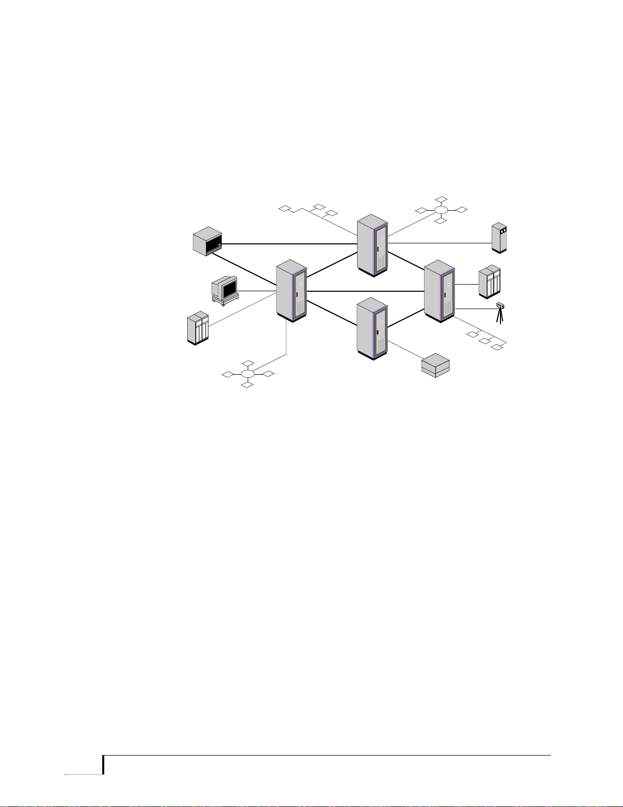
Private Networks Figure 1-1 shows an example of an N.E.T. private network, consisting of
several nodes and topologies. In a network, the Promina 800, 400, 200,
and 100 are referred to as nodes. The logical connections between nodes
are called links. Trunks are the digital transmission facilities over which
voice, data, and video are transmitted.
Figure 1-1 Exam ple of an N.E.T. Pr ivate Network
Promina 800 Installation and Maintenance Promina Series 1 - 3
. . . . . . . . . . . . . . . . . . . . . . . . . . . . . . . . . . . . . . . . . . . . . . . . . . . . . .
Promina 800
Promina 800
Promina 800
Promina 400
T1
T3
T3T3
T1
T1
T1
Graphics
Workstation
Host
Host
Video
Tape
Drive
PBX
Promina 800
Ethernet
Token Ring
Token Ring
Ethernet
Promina Systems Overview
Interface and
Device
Compatibility
A Promina node is compatible with many public network services. It also
supports a wide range of applications by providing transparency to
protocols for specific applications and permitting connections to most
major types of voice, data, and image equipment (Figure 1-2).
Figure 1-2 Equipment Supported by Promina Systems
1 - 4 Promina Series Promina 800 Installation and Maintenance

Promina Systems Overview
. . . . . . . . . . . . . . . . . . . . . . . . . . . . . . . . . . . . . . . . . . . . . . . . . . . . . .
Hardware Features
The Promina processor subsystems provide features and interfaces such
as:
• mass storage provided by the PSM (Promina Server Module)
• non-volatile storage for boot code, run-time code, and the
configuration database
• real time clock
• Ethernet ports
– internal Ethernet port for intranodal communications
– external Ethernet port for Network Management System (NMS)
connectivity
• serial ports
Physical
Interfaces
Call Configuration
Promina nodes uses industry standard physical interfaces to connect with
customer devices. The Promina nodes provide connections for:
• data terminal equipment
• voice equipment compatible to industry standards
• video transmittal and receiving equipment.
For Promina system configurations, features, and options, contact your
local N.E.T. sales representative.
Once the Promina system is installed and tested, the Promina node is
configured.
The number of voice and data calls that can be supported by the Promina
node depends on the following:
• the number of redundant modules
• the number of available logical and physical slots on the node
• the maximum number of database ports
Promina 800 Installation and Maintenance Promina Series 1 - 5

. . . . . . . . . . . . . . . . . . . . . . . . . . . . . . . . . . . . . . . . . . . . . . . . . . . . . .
Promina Systems Overview
Network Management
Using the processor modules, the Promina operator can access the
Operator Interface software to configure the node, monitor the network,
and diagnose network problems from any ASCII asynchronous terminal.
1 - 6 Promina Series Promina 800 Installation and Maintenance

1Chapter 2
. . . . . . . . . . . . . . . . . . . . . . . . . . . . . . . . . . . . . . . . . . . . . .
2Standard Equipment
Modules
This chapter contains an overview of the standard equipment modules for
Promina Series nodes. It includes the following topics:
• Overview on page 2-2.
• Promina Controller Modules Overview on page 2-3.
• Promina 800 Standard Equipment Configuration on page 2-4.
• Promina Standard Equipment Connectivity on page 2-6.
• Promina 800 Node Standard Equipment Redundancy on page 2-7.
• Domain and System Redundancy on page 2-7.
• Nonredundant Configurations on page 2-8.
• Timing Sources on page 2-10.
Promina 800 Installation and Maintenance Promina Series 2 - 1

. . . . . . . . . . . . . . . . . . . . . . . . . . . . . . . . . . . . . . . . . . . . . . . . . . . . . .
Standard Equipment Modules
Overview
The standard set of equipment modules that are part of every Promina
800 model include node processor modules, modules that provide
connection between node shelves, and cards that terminate system buses.
Other standard operating equipment include power supplies, chassis, and
cabinets. You can find procedures for installation of standard equipment
modules in Appendix A, Card Installation.
The types of standard equipment modules vary depending on the type of
node. All standard equipment modules consists of front cards, interface
cards, or both. Table 2-1 lists the cards for standard equipment modules
for each type of node and briefly describes each module.
Node Front Card Interface Card Description
Table 2-1 Promina 800 Standard Equipment Modules
Promina 800
only
Promina 800
(required)
Promina 400
(optional)
Promina
Processor
Module (PPM)
Switching
Exchange
(SX-2)
N/A Shelf Bus
Bus Extender
(BX)
N/A Bus Terminator Terminates system buses (STS only).
Promina
Server Module
(PSM)
PPM Interface
(PPMI)
SX Interface
(SXI-2)
Interface (SBI-2)
BX Interface
(BXI)
PSM Interface
(PSMI)
• PPM resides in the high-speed shelf
(HSS) and controls the node.
• PPMI provides an Ethernet port, an
RS-232/RJ-45 port, and an Alarm
port.
SX-2 provides the switch matrix and
clocking on the node, as well as
communication between shelves.
SBI-2 connects the SX-2 modules to the
HSS.
BX provides the communication link
between the expansion shelf (EXS) or
standard shelf (STS) and the SX-2 on the
HSS-2.
• PSM serves as the node file system
manager and the focal point for local
network management and remote
access administrative and service
communications.
• PSMI provides two Ethernet ports and
two RS-232/RJ-45 ports to support
these PSM functions.
2 - 2 Promina Series Promina 800 Installation and Maintenance

Standard Equipment Modules
. . . . . . . . . . . . . . . . . . . . . . . . . . . . . . . . . . . . . . . . . . . . . . . . . . . . . .
Promina
Controller
Modules Overview
The Promina node processor modules (PPM) and Promina node storage
module (PSM) control the internal logic and communication for the node
and provide the central processing and memory storage for the node. The
controller modules also provide the connections for access to the operator
interface.
The PPMs are high-performance controller cards using the Motorola
68LC060. The PLMs are multifunction controller cards using the
Motorola 68LC040.
The PSM has a 68EC040 microprocessor; it incorporates a hard disk
drive for storage of system code, configuration database, event logs, and
feature module code for Frame Relay Exchange (FRX), LAN-WAN
Exchange (LWX), and ISDN Exchange (ISDNX, also known as
PrimeSwitch Module). The combination of these high-speed
microprocessors and the onboard memory design on the Promina
controller cards enables fast system boot up and a high level of call
performance.
The Promina controller cards use a real time operating system. The
Promina operating system also includes these advanced features:
• DOS-compatible filing system for easy access to files
• Internet Protocol (IP) routing system for accessing files over Promina
and IDNX networks
• Local and remote Simple Network Management Protocol (SNMP)
agent for network management systems
• Internet applications:
– Network File System (NFS) client and server system
– File Transfer Protocol (FTP)
– Remote login (RLogin)
– PPP (Point-to-Point Protocol) access to nodes via modem
For more information on each of the Promina controller modules refer to
Chapter 3, Card Descriptions. You can find the procedures for standard
equipment module installation in Appendix A, Card Installation.
Promina 800 Installation and Maintenance Promina Series 2 - 3

. . . . . . . . . . . . . . . . . . . . . . . . . . . . . . . . . . . . . . . . . . . . . . . . . . . . . .
Air Space
HSS-0
PPM Cards
SX-2 Cards
SX-2 Cards
Trunk Card
PSM Card
EXS 2
EXS 3
Alarm Panel (optional) / Fan
Power Supplies
Power Supplies
T1-Jackfield (optional)/Fans
Voice Card
Power Supply Tray
EXS 1
T3-Jackfield (optional)
Air Space
BX Cards
Standard Equipment Modules
Promina 800 Standard Equipment Configuration
A Promina 800 node must have one high-speed shelf (HSS) and one
standard shelf (STS) or expansion shelf (EXS) with any combination of
additional STS or EXS shelves, up to a maximum of seven shelves. For
more information on these shelves, refer to the Promina System
Components on page 7-1. Also see Appendix A, Card Installation.
A Promina 800 node may consist of either a nonredundant or redundant
configuration of PPM, PSM, SX-2, and BX cards and power supplies.
Refer to Promina 800 Node Standard Equipment Redundancy on page
2-7 for further detail.
A Promina 800 node with three EXS shelves and with redundant PPMs,
SX-2, and BX cards is illustrated in Figure 2-1.
Figure 2-1 Promina 800 standard Equipment Configuration
2 - 4 Promina Series Promina 800 Installation and Maintenance

Standard Equipment Modules
. . . . . . . . . . . . . . . . . . . . . . . . . . . . . . . . . . . . . . . . . . . . . . . . . . . . . .
Standard and Expansion Shelves
The Bus Extender (BX) cards and PSM modules must be installed in an
STS or an EXS. The BX card must reside in the leftmost slots in an STS
(for example, slots 16 and 17) or the rightmost slot in an EXS (for
example, slots 30 and 31).
The PSM can be installed in any slot in an STS or EXS except slots
reserved for BX cards.
High-Speed Shelf (HSS)
The PPM module and Switched Exchange (SX-2) cards must be installed
in an HSS-2 (shelf 0). These cards cannot function in any other type of
shelf.
The SX-2 cards must be installed in the leftmost slots (slots 0 and 1) and
the redundant SX-2 cards must be installed in the rightmost slots (slots 14
and 15). PPM cards can be installed in any HSS slot not reserved for
SX-2 cards.
SX-2 Port-to-Shelf Configuration
Each SX-2 card has four spigots numbered 0 to 3 starting with the bottom
connector. Each spigot provides 16 logical slots: 32 Mbps of bandwidth
per spigot for a total of 128 Mbps per SX-2 card, and a maximum of 256
Mbps with two SX-2 cards.
The SX-2 connects to each shelf through the BX cards (referred to as
BXA and BXB on redundant systems).
The STS shelf contains 12 slots. To maintain “module 16” consistency,
STS slots are numbered as if there are 16 on each shelf (the four missing
slot numbers are discarded and appear as empty when the database is
queried). For example, if shelf 1 slots are numbered 16 to 27, shelf 2 slot
numbers start at 32.
Note: It is important to connect the SX-2 spigots so that the slot numbers are
consecutive; that is, so there are no gaps. For example, in a three-shelf
configuration, shelf 0 connects to spigot 0, shelf 1 to spigot 1, shelf 2 to spigot 2,
etc. The T3 modules can connect to spigots 6 and 7 regardless of gap s because
of clock reference considerations on spigots 0 through 3.
Promina 800 Installation and Maintenance Promina Series 2 - 5

. . . . . . . . . . . . . . . . . . . . . . . . . . . . . . . . . . . . . . . . . . . . . . . . . . . . . .
Auxiliary Port to
Internal Ethernet
Nodal Modem
Console Ports
External Ethernet
External Ethernet
PPM
Front Card
Interface Card
PSM
PPM
PPM
to Terminals
or Workstation
Console Port
to Terminals
or Workstation
Alarm
Interface
Front Card
Interface Card
NMS /LAN
Terminator
Terminator
Standard Equipment Modules
Promina Standard Equipment Connectivity
The Promina node processor modules provide connectivity between the
node processors (by way of internal Ethernet), to NMS or LAN systems
(by way of external Ethernet), to terminal/workstations, and to a remote
access modem. Figure 2-2 illustrates conceptually the standard
equipment connectivity in a Promina 800 with redundant PPMs and a
nonredundant PSM.
Note: PPMs and PSMs in a Promina 800 must be connected by the internal
Ethernet cable even in a nonredundant configuration. The Ethernet connection
enables code loading from the PSM to the PPM. Each end of the Ethernet
connection (including on any T-connector) must have a terminator installed.
Figure 2-2 Promina 800 standard Equipment Connectivity
2 - 6 Promina Series Promina 800 Installation and Maintenance

Standard Equipment Modules
. . . . . . . . . . . . . . . . . . . . . . . . . . . . . . . . . . . . . . . . . . . . . . . . . . . . . .
Promina 800 Node Standard Equipment Redundancy
A Promina 800 node may have redundant PPM and PSM modules.
Redundant PPMs are configured in a multiprocessing system with one
master PPM and the others serving as coprocessors. PSM modules
provide 1:1 redundancy.
A redundant Promina 800 may have two or four SX-2 cards (two
redundant pairs) to support up to eight system components consisting of
shelves or modules that support direct SX-2 connections such as the T3
module.
Note: Each T3/E3 card takes up one SX-2 spigot. Each CX card optionally
takes up one spigot. Each SCLX card takes from 1-2 spigots.
The redundant SX-2 and BX cards provide 1:1 redundancy.
Domain and
System
Redundancy
Promina 800 nodes with redundant standard equipment can be configured
to provide system redundancy through two domains. The required
equipment for each domain in a Promina 800 node is shown in Table 2-2.
Table 2-2 Domain Equipment in Promina 800
Number Equipment per Domain
1-2 HSS-2 shelf (per node; domain independent)
1 Shelf bus interface card
1-2 SX-2 modules
1-n T3 (1-4) and E3 (1-6) modules (domain dependent when
redundant; domain independent when nonredundant)
1-n CX (1-4) modules with T3/E3/OC3 interface ca rd s
1-4 SCLX modules with OC3 interface cards
1-n BX modules (one per STS or EXS shelf)
1-4 PPMs (per node; domain independent)
Note: HSS-2 and PPMs are standard to both domains and are domain
independent. There can be up to four PPMs per node for load-sharing and not
necessarily for redundancy.
All the shelves (EXS/STS), T3/E3 trunk modules, and CX modules (with
T3/E3 interface cards) are connected to both Domain A and Domain B
through spigots on SX-2 cards. The SX-2 spigot on the HSS-2 shelf,
which is shelf 0 (zero), is connected to Shelf Bus Interface (SBI) ports A
Promina 800 Installation and Maintenance Promina Series 2 - 7

. . . . . . . . . . . . . . . . . . . . . . . . . . . . . . . . . . . . . . . . . . . . . . . . . . . . . .
Standard Equipment Modules
and B, respectively; thus the node system has redundant standard
equipment via domains, and with one online and the other offline.
If the system is currently on domain A and a failure is detected on a
standard equipment card (for example, an SX-2, BX, T3, or SCLX, if
cabled and configured redundantly) the system will switch to Domain B.
The node has the highest priority, followed by the shelf, followed by the
trunk module. For example, if a Promina 800 is currently using domain A
and a failure occurs on a Domain A BX module, the Promina will switch
to Domain B, even though the redundant T3 card on Domain B is down.
This causes the T3 span to go down but enables the shelf that had the
failed BX to be restored. In this example, the system will still be
nonredundant.
The operator switches the domain online by entering the Switch Domain
command in the OI.
Nonredundant
Configurations
A Promina 800 node may also be configured as a nonredundant system. A
nonredundant configuration of the Promina 800 node consists of the
following:
• One rack
• One HSS-2
• One to 3 EXS
• One power supply per shelf
• One PSM
• One PPM
• One SX-2
• One T3, E3, or CX (with T3/E3 interface) (optional)
A second PPM is used in a nonredundant Promina 800 node, if needed, to
accommodate the number of load units in the node configuration. In this
situation, the second PPM does not provide redundancy.
A second SX-2 may be needed in a nonredundant Promina 800 node
depending on the number of shelves and whether the node has a
high-bandwidth trunk such as a T3, E3, or CX with T3/E3 interface.
Nonredundant Promina 800 configurations also have some restrictions in
supported components and system capabilities.
• Only EXS shelves (to a maximum of three EXS shelves) are
supported.
2 - 8 Promina Series Promina 800 Installation and Maintenance

Standard Equipment Modules
. . . . . . . . . . . . . . . . . . . . . . . . . . . . . . . . . . . . . . . . . . . . . . . . . . . . . .
• Only one high-bandwidth trunk card such as a T3, E3, or CX (with
T3/E3 interface) is supported.
• A nonredundant configuration cannot support domain redundancy;
the B domain must be disabled in the configuration database to
suppress nonredundant events and alarms.
Promina 800 Installation and Maintenance Promina Series 2 - 9

. . . . . . . . . . . . . . . . . . . . . . . . . . . . . . . . . . . . . . . . . . . . . . . . . . . . . .
Standard Equipment Modules
Timing Sources
A single, central clocking source is vital to the operation of all digital
networks because it synchronizes transmission between communicating
devices. If the clocking of each element in the network is not
synchronized to a standard source, bit errors and frame slips can occur.
Internal clocking is provided as follows:
Table 2-3 Clocking Sources
Node Card
Promina 800 SX-2
The SX-2 module can provide internal timing by way of the timing
signals generated by the onboard crystal oscillator. These cards can also
provide external timing by phase-locking onto external clock sources (for
example, digital transmission facilities, channel banks, or station clocks).
External clocking from customer equipment can also be provided to the
node through various modules including:
• Trunk cards
• Primary Rate Card (PRC) and Two Megabyte Channelized Port
(TMCP) voice cards
• Universal Synchronous Data (USD) data cards
Note: USD data cards are not supported by the Promina 100.
For more information on setting up clocking, refer to the Node
Management manual.
2 - 10 Promina Series Promina 800 Installation and Maintenance

1Chapter 3
. . . . . . . . . . . . . . . . . . . . . . . . . . . . . . . . . . . . . . . . . . . . . .
3Card Descriptions
This chapter describes the front and interface cards for each of the
standard equipment modules, including information on the front panel
components and rear panel connectors. Information is organized by node
type for the Promina 800, 400, 200, and 100. You can find the following
information in this chapter:
• Promina 800 standard Equipment Modules on page 3-2.
• Dial-in Access Modem on page 3-19.
A condensed description is provided in Module Installation Requirements
on page A-2.
Caution: For clarity, illustrations that show connections, components, and
settings for interface cards do not show EMI shielding. Under no circumstances
should EMI shielding be removed from interface cards.
Promina 800 Installation and Maintenance Promina Series 3 - 1

. . . . . . . . . . . . . . . . . . . . . . . . . . . . . . . . . . . . . . . . . . . . . . . . . . . . . .
Card Descriptions
Promina 800 standard Equipment Modules
This section describes the following standard equipment modules:
• Promina Processor Module (PPM)
• Promina Server Module (PSM)
• Switching Exchange Module (SX-2)
• Bus Extender (BX)
This section also describes the bus terminator interface card and the Shelf
Bus Interface (SBI-2).
PPM Module The Promina Processor Module (PPM) consists of a PPM front card and
an interface card (PPMI). The PPM module has the following hardware
and software features:
• A Motorola 68LC060 microprocessor operating at 50 MHz
• 16 MB of DRAM, expandable to 32 MB
• 4 MB flash, expandable to 16 MB
– Boot code residing in flash memory to provide enough memory
space for two complete copies of the Promina software to be
stored
– Support for downloadable field upgrades of boot code
• A console port providing an RS-232 compliant (RJ-45) DTE serial
connection for an OI terminal; this port can be configured for
standard baud rates up to 38.4 kbps or autobaud sensing
• An internal Ethernet port providing for intranodal communication
with other PPMs and PSMs
• Load sharing multiprocessing
The PPM module contains sufficient flash and DRAM memory to load all
system software, including the configuration database. Upon power-up,
the system software is uploaded from the PSM to the PPM. The
configuration database is stored in DRAM. The backup boot storage
allows for processor recovery following a failed boot download or power
failure.
Note: If the PPM modules are configured with 32MB DRAM, consider raising
the “low-ram threshold”. You can modify this value with the modify node
command described in the Modifying Node Parameters on page 8-2 of the Node
Management manual. The command parameter d escription can be found in [16]
Low RAM Event Threshold on page 15-93 of that manual.
3 - 2 Promina Series Promina 800 Installation and Maintenance

Card Descriptions
. . . . . . . . . . . . . . . . . . . . . . . . . . . . . . . . . . . . . . . . . . . . . . . . . . . . . .
Master and Coprocessor Functions
All Promina nodes have an SNMP agent and the Operator Interface (OI)
to enable node management. PPMs have the infrastructure to support
internodal network management services (NMS) communication
requirements, which allows the entire network to be managed from a
single NMS connection.
The PPM can be installed in any slot on the HSS-2 not reserved for an
SX-2 card. One to four PPMs can be installed in a Promina 800 node. One
PPM functions as the master when the system is powered up. If the
master PPM fails or if the operator assigns another PPM to be the master
while online, another PPM then becomes the master.
The distributed nature of the Promina software allows tasks to run on any
of up to four PPMs. Tasks can communicate with each other regardless of
their location. Two classes of PPMs exist: one is designated the master;
the others are coprocessors. When a master PPM restarts, the entire node
restarts. When a coprocessor PPM restarts, only the tasks on that
particular PPM restart.
Certain tasks, such as the TBus Manager and the Call Controller, run only
on the master PPM. The master PPM communicates with other node
“slaves” via the PBus/CBus system and with other nodes via the TBus.
SCLP (Signal Channel Link Protocol) and SSC (Secondary Signaling
Channel) are the mode of communication used to provide the
communication system with other nodes in the network. Refer to Chapter
5, SSC, HTC, and SCLP Ports, for more information on SCLP and SSC
usage.
PPM Front Panel
Figure 3-1 describes the LED status indicators and components on the
PPM front panel.
Promina 800 Installation and Maintenance Promina Series 3 - 3
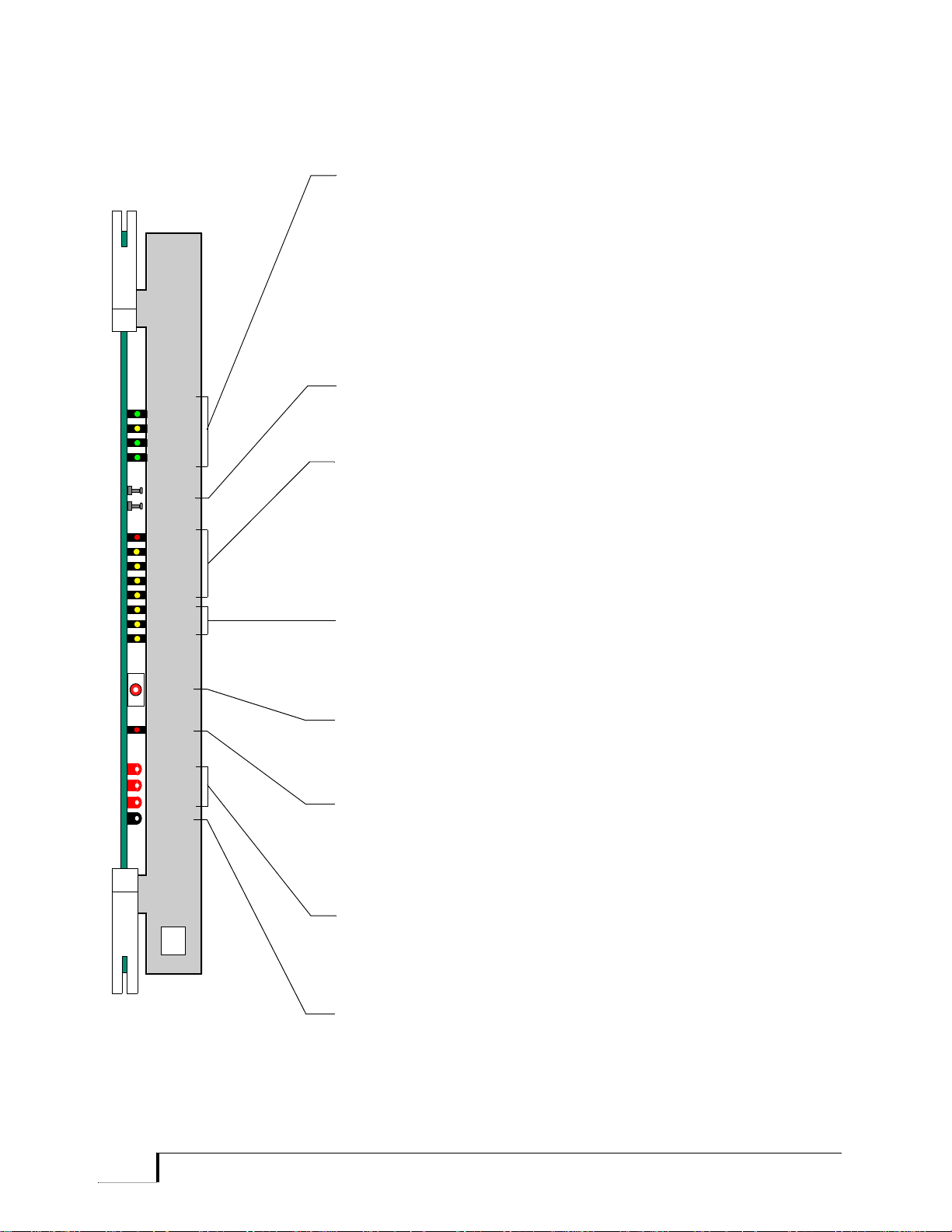
. . . . . . . . . . . . . . . . . . . . . . . . . . . . . . . . . . . . . . . . . . . . . . . . . . . . . .
GND
-5V
PPM
+5V
+12V
3
4
FAULT
6
5
7
TX
RX
CLSN
ONLINE
ASSY
024483
ETHER
2
1
0
BRD
RST
CPU
RST
REV
A
ETHERNET LEDs
ONLINE (Green) When flashing, indicates that the Ethernet
transceiver is online.
COLLISION (Yellow) When flashing, indicates an Ethernet port
collision is occurring.
TRANSMIT (Green) When flashing, indicates the Ethernet signal
is transmitting data packets.
RECEIVE (Green) When flashing, indicates the Ethernet signal
is receiving data packets.
BOARD RESET POSTS
Shorting these connectors causes a complete hardware reset of all
PPM circuits.
ALARM LEDs
7 (Red) Flashes at software startup; when lit, indicates a
Critical alarm.
6 (Yellow) Indicates a Major alarm.
5 (Yellow) Indicates a Minor alarm.
4 (Yellow) Indicates an Informational alarm.
3 (Yellow) Not currently used.
PROCESSOR LEDs (Yellow)
When 2 is lit and 1 and 0 are alternately flashing, this PPM is the
master; if only 0 is flashing, this PPM is a coprocessor.
CPU RESET SWITCH
Pressing this switch initiates a soft (warm) reset.
FAULT LED (Red)
Lit during power-up (until PPM passes diagnostic tests); if it remains
lit, indicates that card has failed the start-up test.
TEST POINTS (Red)
Used to check power supply voltages to the card.
GROUND TEST POINT (Black)
Provides a ground for voltage measurements.
Card Descriptions
Figure 3-1 PPM Front Panel
3 - 4 Promina Series Promina 800 Installation and Maintenance

Card Descriptions
J1, 48-Pin Connector
26-pin Alarm Panel
Interface Connector
Console DTE Port
(YOST)
REV
PPMI
ASSY
Internal Ethernet
(10Base2)
. . . . . . . . . . . . . . . . . . . . . . . . . . . . . . . . . . . . . . . . . . . . . . . . . . . . . .
PPMI Card The PPM Interface (PPMI) is an interface card that attaches to the PPM
front card and resides on the Promina 800’s HSS-2. The PPMI includes
the pulse transformers, voltage converter, transceiver, and associated
components to support the media interface for 10Base2 Ethernet.
The PPMI is made up of three primary connectors (see Figure 3-2):
• Thin coax (10Base2) Ethernet BNC connector for intranodal
communications with other PPM and PSM modules (commonly
referred to as Internal Ethernet interface)
• DTE (YOST) connector for console port connectivity
• N.E.T. proprietary DB-26 26-pin alarm interface connector that
connects to an optional alarm panel
Figure 3-2 PPMI Connectors
Promina 800 Installation and Maintenance Promina Series 3 - 5

. . . . . . . . . . . . . . . . . . . . . . . . . . . . . . . . . . . . . . . . . . . . . . . . . . . . . .
Card Descriptions
SX-2 Module The SX-2 provides the clocking and switching functions for the HSS-2,
EXS and STS in a Promina 800. It also provides additional bandwidth to
the T3/E3 trunk card to supplement TBus bandwidth limitations.
Each SX-2 card provides up to 128 Mbps of switching bandwidth (256
Mbps for two SX-2s). Four shelves provide 128 Mbps, and eight shelves
provide 256 Mbps capacity. Both TBus and PBus information pass
through the SX-2.
In addition, the SX-2 module can provide the internal timing source to a
network via timing signals generated by its onboard oscillator, or it
phase-locks onto the incoming signal of an external clock source and
distributes it to the other nodes in the network. The SX-2 module can
accept up to eight clock references. The LEDs REF0 through REF7 (as
shown on the SX-2 card front panel) indicate when a clock reference is
present.
The Promina 800 contains two pairs of SX-2s per node for redundancy.
These cards can support additional shelves and T3/E3 trunk cards. If the
primary SX-2 set fails, the node switches domains and the backup SX-2
set automatically provides clocking and switching.
SX-2 Front Panel
Figure 3-3 describes the LED status indicators and components on the
SX-2 front panel.
3 - 6 Promina Series Promina 800 Installation and Maintenance

ASSY
SX-2
REF7
REF6
REF5
REF4
REF3
REF2
REF1
REF0
ON LINE
MSTR
SYNC
LOSS
RST
FLT
4KHz
MSYNC
5.12 MHz
+12V
+5V
-5V
-12V
GND
REV
D
GROUND TEST POINT (Black)
Provides a ground for voltage measurements.
MASTER LED (Green)
Lit when the internal oscillator is selected (that is, the node is not
locked to an external clock source). When flashing quickly , the card is
in holdover mode.
BOARD RESET POSTS
Shorting these connectors causes a complete hardware reset of the
SX-2 card.
ON LINE LED (Green)
When lit, this LED indicates that this card is the active card providing
clocking and switching to the node.
CLOCK SIGNAL TEST POINTS
Front panel test points for clock signals generated by the SX-2.
CLOCK REFERENCE LEDs (Green)
References 0-7
When flashing, indicates the reference clock source that is being used
(currently selected). When lit, indicates that the clock reference is
present but is not currently in use. During boot, these LEDs indicate
that self tests are in progress.
HOT INSERTION PLUG
Connector for umbilical cord plug.
TEST POINTS (Red)
Used to check power supply voltages.
SYNC LOSS LED (Red)
When on, this LED indicates an alarm condition because of loss of
the reference signal or because of clock malfunction. Master LED
should also be on. PLL (phase lock loop) of the online card locks to
the internal OSC. The offline card still tracks the online card.
FAULT LED (Red)
Lit during power-up; if lit after power-up is complete, the card has
failed. When flashing, indicates the self-test diagnostics have indicated
an error.
Card Descriptions
. . . . . . . . . . . . . . . . . . . . . . . . . . . . . . . . . . . . . . . . . . . . . . . . . . . . . .
Figure 3-3 SX-2 Front Panel
Promina 800 Installation and Maintenance Promina Series 3 - 7

. . . . . . . . . . . . . . . . . . . . . . . . . . . . . . . . . . . . . . . . . . . . . . . . . . . . . .
Card Descriptions
SXI-2 Card The SXI-2 interface card pr ovides four spigots (15-pin D-subconnectors)
used to connect to the SBI-2 (shelf bus interface) on the high-speed shelf,
the BXI card on the standard and expansion shelves, and the T3I/E3I
cards on the high-speed shelf.
SX-2 cards must use SXI-2 interface cards. (The SXI and SXI-2 are not
interchangeable. SX-2 and SXI-2 cards are required for Promina 800
nodes.)
The spigots are labeled 0, 1, 2, and 3 starting from the bottom. The spigot
number of the SXI-2 connected to the shelf determines the shelf number.
For example:
• Spigot 0 connects to high-speed shelf 0
• Spigot 1 connects to shelf 1
• Spigot 2 connects to shelf 2
• Spigot 3 connects to shelf 3
To support more than four shelves, a second SX-2 is required. In this
case, spigot 0 (on the second card) connects to shelf 4, spigot 1 connects
to shelf 5, and so on.
The backplane jumper on the EXS and STS must also be set.
SXI-2 Connectors
Figure 3-4 illustrates the connectors for the SX-2 Card Interface.
Note: There are no active components on the SXI-2.
3 - 8 Promina Series Promina 800 Installation and Maintenance

Card Descriptions
60-Pin
15-Pin Connector
Rev
SXI-2
ASSY
-0-
-1-
-2-
-3-
Port 0 (shelves 0 and 4)
15-Pin Connector
Port 1 (shelves 1 and 5)
15-Pin Connector
Port 2 (shelves 2 and 6)
15-Pin Connector
Port 3 (shelves 3 and 7)
Connector
. . . . . . . . . . . . . . . . . . . . . . . . . . . . . . . . . . . . . . . . . . . . . . . . . . . . . .
Figure 3-4 SXI-2 Connectors
Promina 800 Installation and Maintenance Promina Series 3 - 9

. . . . . . . . . . . . . . . . . . . . . . . . . . . . . . . . . . . . . . . . . . . . . . . . . . . . . .
Domain A (SBI B)
SBI Cards
15 Pin SX-2
Interface
Test Points
FTP1 +12 VDC (Blue)
FTP2 -2 VDC (Yellow)
FTP3 +5 VDC (Red)
FTP4 -5 VDC (Green)
FTP5 GND (Black)
P/S 1 BOT
P/S 2 TOP
Domain B (SBI A)
I/O
I/O
Card Descriptions
SBI Card The SBI-2 card prov ides the interface between the SX-2 and a high-speed
shelf. SBI-A connects to SXA1 on Spigot 0, and SBI-B connects to SXB1
on Spigot 0.
Figure 3-5 SBI Cards, Domains A and B
BX Front Panel The BX module functions as the communication path between the SX-2
card (on the HSS-2) and the STS or EXS. BX cards must be installed in
an STS or an EXS. Figure 3-6 describes the front panel components on
3 - 10 Promina Series Promina 800 Installation and Maintenance
the BX card.

Card Descriptions
BX
ASSY
-5.2V
GND
REV
FAULT
CBUS
ONLINE
J
+5V
RST
FAULT LED (Red)
When on, this LED indicates that a failure has been detected on
the card.
RESET SWITCH
Toggle Switch. Resets the card. Also used when inserting and
removing the card.
HOT INSERTION PLUG
Connector for umbilical cord plug. Supplies operating voltages for
installing cards that are not hot insertable (T3).
ONLINE LED (Green)
When on, this LED indicates that this card is the active card and
is transmitting clock and TBus data to the shelf.
CBUS LED (Yellow)
When flashing or dim, indicates that the module is accessing the
CBus. When lit, indicates that the module is dominating the CBus
and that there is a malfunction.
TEST POINTS (Red)
Used to check the power supply voltages of the card.
GROUND TEST POINT (Black)
Provides ground for voltage measurements.
NORM
CARD
. . . . . . . . . . . . . . . . . . . . . . . . . . . . . . . . . . . . . . . . . . . . . . . . . . . . . .
Figure 3-6 BX Front Panel
Promina 800 Installation and Maintenance Promina Series 3 - 11

. . . . . . . . . . . . . . . . . . . . . . . . . . . . . . . . . . . . . . . . . . . . . . . . . . . . . .
EMI Shield
in Front of Card
Backplane
Connector
15-Pin Connector
Card Descriptions
BXI Connectors The BXI card, shown in Figure 3-7, connects to the SX-2 card through a
single spigot (15-pin D connector).
Note: There are no active components on this interface card.
Figure 3-7 BXI Connectors
3 - 12 Promina Series Promina 800 Installation and Maintenance

Card Descriptions
. . . . . . . . . . . . . . . . . . . . . . . . . . . . . . . . . . . . . . . . . . . . . . . . . . . . . .
Promina Server
Module
The Promina Server Module (PSM) is an intelligent network file server
that is installed in a Promina 800 STS or EXS and is optional in the
Promina 400. It consists of a front card and a rear Promina Server Module
Interface (PSMI) card. The PSM does the following:
• Acts as the central point for data storage
• Interfaces with the hard drive, modem, internal Ethernet connection
to the PPM and PLM cards, and provides the external Ethernet
connection to an NMS workstation
• Uses a DOS-compatible file system for storage of system code,
configuration database, event logs, and network management data
• Supports two serial ports (DTE) for modem and terminal connectivity
with standard, programmable baud rates up to 38.4 kbps
• Provides the physical connections and path for processor and server
module software upgrades
The PSM offers the following features:
• A low-profile ATA hard drive mounted directly on the PSM card
• 4 MB of flash memory, expandable to 16 MB, that holds two copies
of the boot code
• 4 MB of DRAM, expandable to 32 MB
• Real time clock/calendar for time-stamping disk files
The PSM’s nodal file system provides mass storage for a nodal database,
several versions of Promina application code, and expanded event logs.
The runtime code is downloaded from the PSM to PPMs and PLMs via
the internal Ethernet.
The External Ethernet connects the PSM to a Network Management
System (NMS) workstation or a LAN and supports a maximum bit rate of
10 Mbps. The External Ethernet port autosenses between either 10Base2
port or 10BaseT port media. (Only one type of External Ethernet port
may be used at a time, not both.)
PSM Redundancy
There can be a maximum of two PSMs per node. At startup the PSM
software establishes which module is primary (online) and which is
secondary (offline). To provide service or be available for service to the
PPMs or PLMs in the node, a PSM must be either online or offline,
respectively. The online PSM is the currently active PSM; the offline is
the hot-standby PSM.
Promina 800 Installation and Maintenance Promina Series 3 - 13

. . . . . . . . . . . . . . . . . . . . . . . . . . . . . . . . . . . . . . . . . . . . . . . . . . . . . .
Card Descriptions
For a PSM to be online or offline, it must have a configuration database or
a boot configuration (psmparms) file. Refer to Chapter 5, SSC, HTC, and
SCLP Ports, for more information on PSM configurations.
The primary (online) PSM keeps the disk database on the offline PSM up
to date via a Disk Mirroring task. Whenever the database is saved to the
PSM disk, the new database will be mirrored to the offline PSM. If there
is only a single online PSM and a redundant PSM is installed in the node,
then the database will be mirrored to that PSM directly.
In a redundant configuration a specialized Y cable is used to connect to a
nodal modem. In this redundant configuration, only the primary (online)
PSM can communicate with the DCE device while the other PSM is
placed in the offline mode.
PSM Front Panel
Figure 3-8 describes the status indicators and components on the PSM
front panel.
3 - 14 Promina Series Promina 800 Installation and Maintenance
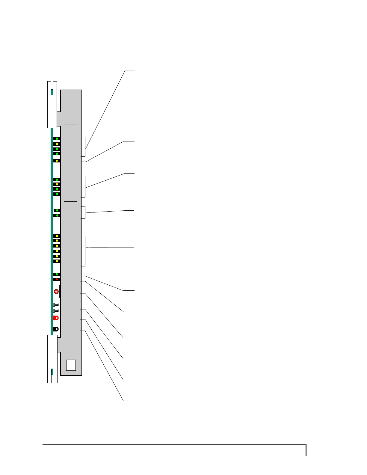
PSM
ASSY
024491
+5V
GND
REV
5
4
3
2
1
0
ACT
FAULT
CPU
CLSN
TX
RX
RST
BRD
RST
T-ACT
ON
RX
CLSN
TX
ON
A
BOARD
DISK
HDD
ON
ETHER.
INT.
ETHER.
EXT.
VOLTAGE TEST POINTS (Red)
Used to check power supply voltages to the card.
CPU RESET SWITCH
Depressing the button forces a soft reset.
EXTERNAL ETHERNET LEDs
ONLINE (Green) Indicates the Ethernet transceiver is in active
mode.
COLLISION (Yellow) When flashing, indicates an Ethernet collision.
TRANSMIT (Green) When flashing, indicates Ethernet is
transmitting.
RECEIVE (Green) When flashing, indicates Ethernet is receiving.
HARD DISK LEDs (Green)
ON Lit when the hard disk is ready to use.
HDD Flashing while the processor accesses the hard disk; off while
the disk is idle.
MODULE STATUS LEDs (Yellow)
Signal various stages of the powerup and diagnostics process for the
PSM. At startup all are lit for two seconds, then are off for one second.
As powerup and diagnostics complete successfully, the LEDs light in
ascending order (0 to 5).
INTERNAL ETHERNET LEDs
Functions are identical to External Ethernet LEDs (see above), but for
the Internal Ethernet.
FAULT LED (Red)
Indicates a fault in the PSM. On failure of a test, this LED flashes for
3 seconds before the module reboots.
ACTIVE LED (Green)
Lit when the PSM is active; off when it is in standby mode.
BOARD RESET POSTS
Short these contact posts to perform a hard reset of the card.
GROUND TEST POINT (Black)
Provides a ground for voltage measurements.
TWISTED PAIR-ACTIVE LED (Yellow)
Lit when the PSM is in twisted pair mode and the link is active.
Card Descriptions
. . . . . . . . . . . . . . . . . . . . . . . . . . . . . . . . . . . . . . . . . . . . . . . . . . . . . .
Figure 3-8 PSM Front Panel
Promina 800 Installation and Maintenance Promina Series 3 - 15

. . . . . . . . . . . . . . . . . . . . . . . . . . . . . . . . . . . . . . . . . . . . . . . . . . . . . .
Card Descriptions
Promina Server
Module Interface
The Promina Server Module Interface (PSMI) is an interface card that
provides two Ethernet interfaces and two RS-232 compliant (YOST)
interfaces for the PSM front card. Figure 3-9 illustrates the connectors on
the PSMI.
Features of the PSMI are shown below:
Table 3-1 PSMI Features
Interface Type Description
External Ethernet I/F Single thin coax 10Base2 (BNC) and one
twisted pare (UTP) 10BaseT Ethernet
connector for NMS connectivity. (Only one
connector type, either 10Base2 or 10BaseT,
can be used at a time; simultaneous use is not
permitted.)
Internal Ethernet I/F One thin coax 10Base 2 Ethernet connector for
intranodal communications with Promina
processor cards.
Auxiliary Port One auxiliary YOST connector for modem
(DTE) connectivity.
Console Port One console YOST connector for
terminal/console (DTE) connectivity.
3 - 16 Promina Series Promina 800 Installation and Maintenance
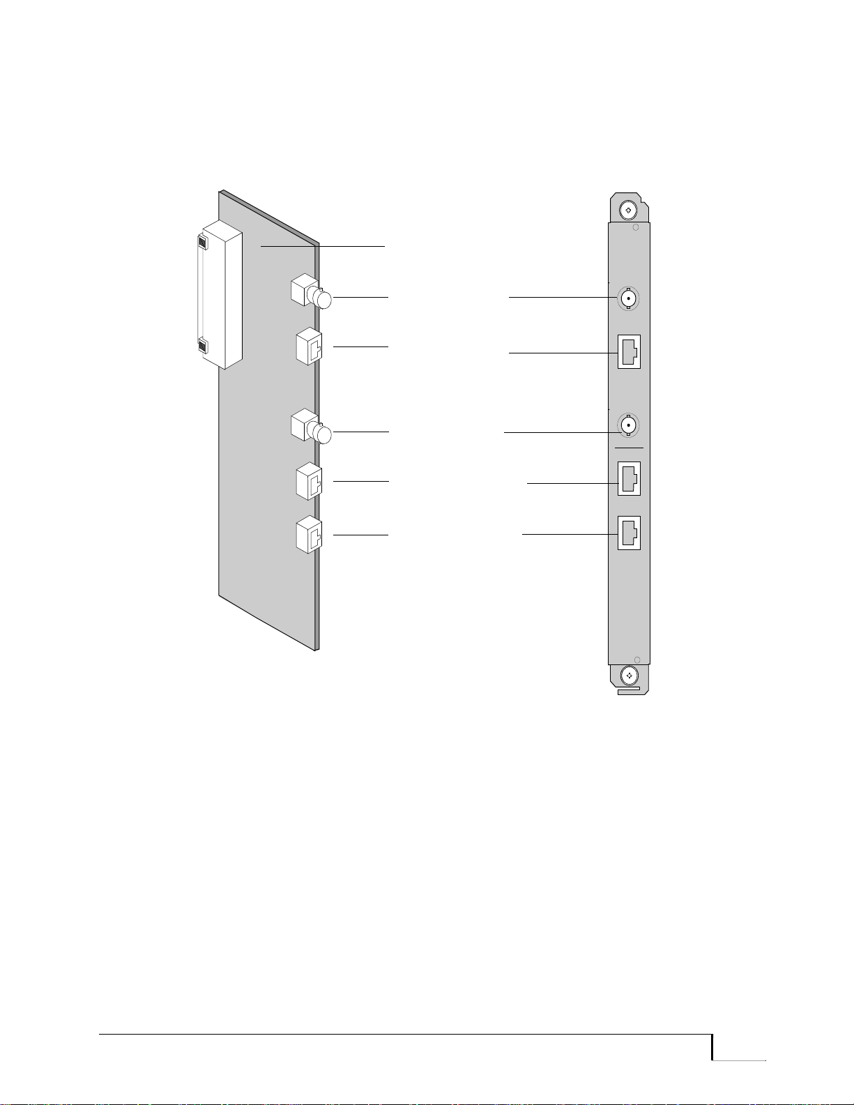
Card Descriptions
J1, 96-Pin Connector
Auxiliary DTE Port
Internal Ethernet
(10Base2)
(YOST)
PSMI/F
ASSY
Console DTE Port
(YOST)
External Ethernet
External Ethernet
(10Base2)
(10Base-T)
. . . . . . . . . . . . . . . . . . . . . . . . . . . . . . . . . . . . . . . . . . . . . . . . . . . . . .
Figure 3-9 PSMI Connectors
Promina 800 Installation and Maintenance Promina Series 3 - 17

. . . . . . . . . . . . . . . . . . . . . . . . . . . . . . . . . . . . . . . . . . . . . . . . . . . . . .
Battery Connector
96-Pin DIN
Backplane
Connectors
(not used)
Card Descriptions
Bus Terminator Each standard shelf (STS) must have a bus terminator to serve as the
endpoint of the system buses. This card does not have a front card. Figure
3-10 illustrates a bus terminator card.
The card plugs into the left-most slot of the backplane when viewed from
the back of the unit. The battery charging circuitry is not used.
Figure 3-10 Bus Terminator Connectors
3 - 18 Promina Series Promina 800 Installation and Maintenance

Card Descriptions
. . . . . . . . . . . . . . . . . . . . . . . . . . . . . . . . . . . . . . . . . . . . . . . . . . . . . .
Dial-in Access Modem
The Promina Series provides remote dial-in capabilities into all Promina
nodes via a modem. The purpose of the dial-in access is to enable
Technical Support access to Promina networks and to allow for remote
upgrading of Promina system software and CPU Boot code. Dial-in
access is password protected and has an optional dial-back verification
procedure.
The modem has non-volatile configuration storage and remote
configuration and diagnostics capability.
• For Promina 800 nodes, a modem is connected via an adapter DB-25
to RJ-45 cable to the auxiliary port on a PSMI.
• For Promina 800 nodes with a redundant PSM, the modem is
connected to the auxiliary ports on each PSMI card via a Y cable.
Promina 800 Installation and Maintenance Promina Series 3 - 19

. . . . . . . . . . . . . . . . . . . . . . . . . . . . . . . . . . . . . . . . . . . . . . . . . . . . . .
Card Descriptions
3 - 20 Promina Series Promina 800 Installation and Maintenance

1Chapter 4
. . . . . . . . . . . . . . . . . . . . . . . . . . . . . . . . . . . . . . . . . . . . . .
4Software Configuration
This chapter contains information on how to use the Operator Interface
(OI) to install standard equipment modules, query card configurations,
and configure the speed on the processor ports. It also includes a
description of the parameters and configuration displays. The following
topics are discussed in this chapter:
• Card Installation on page 4-2.
• Standard Equipment Parameters on page 4-6.
• Processor Card Parameters on page 4-6.
• PSM Card Parameters on page 4-7.
• Card Query Displays on page 4-10.
• Processor Card Configurations on page 4-10.
• Card Configuration Descriptions on page 4-12.
• Query PSM Displays on page 4-18.
• PSM Card Configuration Descriptions on page 4-19.
• SX-2 Card Configuration on page 4-20.
• BX Card Configuration on page 4-22.
• Console Port Settings on page 4-24.
Refer to the Chapter 8, Operator Interface Commands for a listing of all
commands and information about using menus and expert mode.
Promina 800 Installation and Maintenance Promina Series 4 - 1

. . . . . . . . . . . . . . . . . . . . . . . . . . . . . . . . . . . . . . . . . . . . . . . . . . . . . .
Software Configuration
Card Installation
After physically installing the standard equipment cards (see Appendix
A, Card Installation), use the Operator Interface to add the cards to the
configuration database and to initialize the cards in the node. The node
processor card’s parameter data is flooded throughout the network during
the initialization process. Refer to the Node Management manual for
additional explanation and procedures.
Note: The PSM should be installed first, before IP Access Lists are created.
The procedure for installing a PSM differs from the general procedures
used for other standard equipment cards. The PSM is not installed
through the card ID (for example, C3) as with other node cards. It is
installed by using the ins psm command rather than the Install Card
command. The typical procedure for installing a PSM is shown in
Example 4-3.
The general card installation procedure is provided below. Examples for
the PPM (Example 4-1) and the PLM and IPLM (Example 4-2) are
shown following the procedure. All of these examples assume the
operator has already logged into the Operator Interface. Following the
examples are descriptions of the modifiable parameters.
Card Installation
After Node
Initialization
Note: The IPLM installation (processor sector) is performed exactly the same
as the PLM.
To install a card after node initialization has been performed:
1. Enter the Install Card (or Install PSM) command at the prompt.
2. Enter the card ID (slot number) of the card to be installed (not
applicable with PSM).
3. Enter the number that corresponds to the card to be installed or press
the Return key to accept the default card type. The default card type
is in square brackets (for example, [PPM]).
4. If the card does not have any parameters, skip this step. To change
the default parameters, enter the parameter index, specify the new
parameter value, and press Return. Entering a ? displays the valid
inputs for the parameter. When complete, press Return to confirm
that the parameters are correct.
5. When prompted to activate the card (the card is available for
service), press Return to activate the card or enter N. If the card is
not activated, the software displays an enable-card prompt (the card
is available for testing). Press Return to enable the card or enter N.
4 - 2 Promina Series Promina 800 Installation and Maintenance

Software Configuration
. . . . . . . . . . . . . . . . . . . . . . . . . . . . . . . . . . . . . . . . . . . . . . . . . . . . . .
Example 4-1 PPM Card Installation
INSTALL which CARD(s)? [ALL ON THIS NODE]
CARD ID = c3
*** Slot N5C3 contains card type PPM.
Do you want to install card N5C3? [YES]
YES OR NO =
*** Installable Card Types ***
[ 0] TRK [21] HSD-2 [42] E3-TRK
[ 1] LDCELP12 [22] TMCP [43] VCFAX-24
[ 2] LDCELP24 [23] T3-TRK [44] VCFAX-12
[ 3] CX [24] QXP [45] PX-3
[ 4] URD [25] TK64 [46] TRK-3
[ 5] QSD [26] I422-TRK [47] ECHOX
[ 6] INTU-560 [27] QASD [48] APX
[ 7] TRK-2 [28] HDVC24 [49] SX-2
[ 8] HSD [29] HDVC12 [50] PLM
[ 9] DS-1 [30] QAVP [51] PPM
[10] USD [31] BX [52] LDCELP6
[11] MEM [32] SX [53] HLC
[12] QSD-2 [33] HPC [54] PVEC
[13] TK56 [34] DS0B [55] PVE24
[14] PRC [35] PX [56] HINTU
[15] DS0A [36] PX-2 [57] SCLX
[16] VC31 [37] PVAC [58] TWC
[17] VC62 [38] PVA [59]* IP-TRK
[18] DMD [39] LS-TRK
[19] INTU-558 [40] SATRK
[20] X50 [41] PX PLUS
NOTE: '*' marks default selection.
Enter card type for card N5C3? [PPM]
CARD TYPE =
*** PPM Card N5C3 has been INSTALLED.
*** PPM card N5C3 Configuration Parameters ***
[ 0] Alarm/Monitor Interface = YES
Enter parameter index (or hit RETURN to continue)
PARAMETER INDEX =
Are all parameters correct? [YES]
YES OR NO =
*** PPM record updated
Do you want to ACTIVATE card N5C3? [YES]
(Enter '?' to display card configuration.)
YES OR NO =
*** PPM N5C3 has been ENABLED
*** PPM N5C3 has been ACTIVATED
*** Command Complete ***
Promina 800 Installation and Maintenance Promina Series 4 - 3

. . . . . . . . . . . . . . . . . . . . . . . . . . . . . . . . . . . . . . . . . . . . . . . . . . . . . .
Software Configuration
Example 4-2 PLM and IPLM Card Installation
INSTALL which CARD(s)? [ALL ON THIS NODE]
CARD ID = c0
*** Slot N5C0 contains card type PLM.
Do you want to install card N5C0? [YES]
YES OR NO =
*** Installable Card Types ***
[ 0] TRK [21] HSD-2 [42] E3-TRK
[ 1] LDCELP12 [22] TMCP [43] VCFAX-24
[ 2] LDCELP24 [23] T3-TRK [44] VCFAX-12
[ 3] CX [24] QXP [45] PX-3
[ 4] URD [25] TK64 [46] TRK-3
[ 5] QSD [26] I422-TRK [47] ECHOX
[ 6] INTU-560 [27] QASD [48] APX
[ 7] TRK-2 [28] HDVC24 [49] SX-2
[ 8] HSD [29] HDVC12 [50] PLM
[ 9] DS-1 [30] QAVP [51] PPM
[10] USD [31] BX [52] LDCELP6
[11] MEM [32] SX [53] HLC
[12] QSD-2 [33] HPC [54] PVEC
[13] TK56 [34] DS0B [55] PVE24
[14] PRC [35] PX [56] HINTU
[15] DS0A [36] PX-2 [57] SCLX
[16] VC31 [37] PVAC [58] TWC
[17] VC62 [38] PVA [59]* IP-TRK
[18] DMD [39] LS-TRK
[19] INTU-558 [40] SATRK
[20] X50 [41] PX PLUS
NOTE: '*' marks default selection.
Enter card type for card N5C0? [PLM]
CARD TYPE =
*** PLM Card N5C0 has been INSTALLED.
*** PLM card N5C0 Configuration Parameters ***
[ 0] Alarm/Monitor Interface = YES
[ 5] Aux Port PPP access = DISABLED
[ 6] PPP Baud Rate = 38400
[ 7] PPP Local IP = 0.0.0.0
[ 8] PPP Remote IP = 0.0.0.0
[ 9] PPP Tyco Device = /tyCo/1
[10] MTU Size = 576
Enter parameter index (or hit RETURN to continue)
PARAMETER INDEX =
Are all parameters correct? [YES]
YES OR NO =
*** PLM record updated
Do you want to ACTIVATE card N5C0? [YES]
(Enter '?' to display card configuration.)
YES OR NO =
*** PLM N5C0 has been ENABLED
*** PLM N5C0 has been ACTIVATED
4 - 4 Promina Series Promina 800 Installation and Maintenance

Software Configuration
. . . . . . . . . . . . . . . . . . . . . . . . . . . . . . . . . . . . . . . . . . . . . . . . . . . . . .
*** Command Complete ***
Example 4-3 PSM Card Installation
Enter command
< install psm
INSTALL PSM on which node? [THIS NODE]
NODE ID =
***PSM Configuration Parameters ***
[ 0] Console Baud Rate = 9600
[ 1] Auxiliary Baud Rate = 9600
[ 2] External IP = 172.20.42.182
[ 4] Subnet Mask = 0xffff0000
[ 5] PSM1 Assigned CardID = 24
[ 6] PSM2 Assigned CardID = 0
[10] Aux Port PPP access = DISABLED
[11] PPP Baud Rate = 38400
[12] PPP Local IP = 172.20.50.25
[13] PPP Remote IP = 172.20.50.50
[14] PPP TyCo Device = /TYCO/1
[15] MTU Size = 576
Enter parameter index (or hit RETURN to continue)
PARAMETER INDEX =
Are all parameters correct? [YES]
YES OR NO =
*** PSM record updated
*** Command Complete ***
Promina 800 Installation and Maintenance Promina Series 4 - 5

. . . . . . . . . . . . . . . . . . . . . . . . . . . . . . . . . . . . . . . . . . . . . . . . . . . . . .
Software Configuration
Standard Equipment Parameters
Among the standard equipment cards, only the node processor modules
(PPM, PSM, PLM, and IPLM) have modifiable parameters. The type and
number of modifiable parameters vary among the card types. Refer to the
previous card installation examples to see which parameters apply to each
card. The installation examples also show the initial or default parameters
for each card.
Processor Card
Parameters
The PPM has only one modifiable parameter, Alarm/Monitor Interface,
which is also a parameter for the PLM and IPLM. Modifiable parameter
descriptions for the PPM, PLM, and IPLM follow.
[0] Alarm/Monitor Interface
Values are Yes (default) or No.
The alarm panel interface is a 26-pin connector (shown in Figure 3-2) on
the PPMI and PLMI cards that is cabled to the optional alarm panel. This
parameter is always set to Yes even if there is no alarm panel installed on
the node. If this parameter is set to No, the PPM and PLM will not
recognize alarms related to external power failures such as a PDU line.
Use the Modify External Alarm Threshold command to cause audible
and visual alarms to be generated on the alarm panel when an alarm
meeting the value specified by this command occurs on the node or in the
network. Audible and visual alarms are also generated when there is a
power supply failure. These alarms are logged in the alarm and event
logs.
[5] PPP on Aux Port
The values are Disabled (default) or Enabled.
The Point-to-Point Protocol (PPP) parameters enable sending and
receiving IP packets remotely over the auxiliary port on the PLM and
IPLM by TAC via the node modem.
To modify PPP parameters for the PLM and IPLM, use the Install Card
or Modify Card commands. As with other parameters for the PLM and
IPLM, the PLM and IPLM must be disabled to install or modify
parameters. (If the PLM or IPLM is disabled, it will bring down any
existing PPP connection.) No card or node restart is required to configure
or modify the PPP parameters on the PLM and IPLM.
4 - 6 Promina Series Promina 800 Installation and Maintenance

Software Configuration
. . . . . . . . . . . . . . . . . . . . . . . . . . . . . . . . . . . . . . . . . . . . . . . . . . . . . .
[6] PPP Baud Rate
The values are 1200, 2400, 4800, 9600, 19200, 14400, 19200, 28800,
38400 (default), 57600, and 115200.
This parameter is the baud rate associated with the PPP connection for the
host processor (PLM and IPLM) end. Both ends of the PPP connection
should be configured to have the same baud rate.
[7] PPP Local IP
The value is 0.0.0.0 (default) or the IP address associated with the local
(host node) side of the PPP connection.
[8] PPP Remote IP
The value is 0.0.0.0 (default) or the IP address of the remote side of the
PPP connection.
[9] PPP TyCo Device
PSM Card
Parameters
The value is the type of serial device and port number; /tyCo/1 is the
default.
The default, /tyCo/1, is the only appropriate value for the auxiliary port
on a PLM and IPLM. The term, tyCo, is the standard representation for
serial terminal devices in the VXWorks operating system software. The
tyCo port number for the auxiliary port is 1.
[10] MTU Size
The values are 256 to 5000 (default is 576).
The value is the Maximum Transmit Unit (MTU) that is to be used for
this PPP connection (this value must match the value used by the remote
end).
The modifiable parameters for the PSM and their descriptions follow.
[0/1] Console/Auxiliary Baud Rate
The values are 1200, 2400, 4800, 9600 (default for console port), 14400,
19200, 28800, 38400, 57600, 115200, and Autobaud (default for auxiliary
port).
This parameter is the baud rate associated with the console or auxiliary
port on the PSM when used for a TTY connection. Both ends of the
connection should be configured to have the same baud rate.
Promina 800 Installation and Maintenance Promina Series 4 - 7

. . . . . . . . . . . . . . . . . . . . . . . . . . . . . . . . . . . . . . . . . . . . . . . . . . . . . .
Software Configuration
[2] External IP
The value is 0.0.0.0 (default) or the assigned IP address for the PSM.
The External IP settings are Class A, B, or C IP addresses to be set when
installing the PSM card. T ypically a network administrato r will assign an
appropriate IP address for the External Ethernet IP. For more information
about IP addresses refer to the Node Management manual.
[4] Subnet Mask
The value is 0xffff0000 (default) or the IP address (in binary) assigned to
the PSM to identify it to external network systems.
This parameter sets the subnet mask (network, subnet, and host IDs) for
the PSM. This mask has a 32-bit value containing binary 1 bits for
network ID and subnet ID, and binary 0 bits for host ID. The subnet mask
is the section of the IP address that determines the network destination as
used by routers. A router always reads the decimal numbers between the
dots (.) as octets (groupings of 8 bits). For more information about setting
the subnet mask refer to the Node Management manual.
Typically a network administrator will assign appropriate values.
Note: If a subnet mask value is entered that is out of the range of the IP network
identifier, it may not FTP to the targeted PSM.
[5/6] PSM1/2 Assigned CardID
The value is 0 (default) or the slot number for the respective PSM card.
This parameter sets the PSM’s card identification. Since PSM cards are
not identified by the node as with other cards in Promina nodes, the
PSM’s slot number is entered as the PSM card ID.
[10] PPP on Aux Port
The values are Disabled (default) or Enabled.
The Point-to-Point Protocol (PPP) parameters enable the sending and
receiving of IP packets over the auxiliary port on the PSM and is intended
for remote access use by TAC via the node modem.
Use the Install PSM or Modify PSM commands at initial installation or
when modifying the PPP parameters on the auxiliary port on the PSM. No
card or node restart is required to configure or modify the External IP
address or the PPP parameters on the PSM.
4 - 8 Promina Series Promina 800 Installation and Maintenance

Software Configuration
. . . . . . . . . . . . . . . . . . . . . . . . . . . . . . . . . . . . . . . . . . . . . . . . . . . . . .
[11] PPP Baud Rate
The values are 1200, 2400, 4800, 9600 (default), 19200, 14400, 19200,
28800, 38400, 57600, and 115200.
This parameter is the baud rate associated with the PPP connection for the
host processor (PSM) end. Both ends of the PPP connection should be
configured to have the same baud rate.
[12] PPP Local IP
The value is 0.0.0.0 (default) or the IP address associated with the local
(host node) side of the PPP connection.
[13] PPP Remote IP
The value is 0.0.0.0 (default) or the IP address of the remote side of the
PPP connection.
[14] PPP TyCo Device
The value is the type of serial device and port number; /tyCo/1 is the
default.
The default, /tyCo/1, is the only appropriate value for the auxiliary port
on a PLM and IPLM. The term, tyCo, is the standard representation for
serial terminal devices in the VXWorks operating system software. The
tyCo port number for the auxiliary port is 1.
[15] MTU Size
The values are 256 to 5000 (default is 576).
The value is the Maximum Transmit Unit (MTU) that is to be used for
this PPP connection (this value must match the value used by the remote
end).
Promina 800 Installation and Maintenance Promina Series 4 - 9

. . . . . . . . . . . . . . . . . . . . . . . . . . . . . . . . . . . . . . . . . . . . . . . . . . . . . .
Software Configuration
Card Query Displays
After a card is installed, the operator can query the card through the
Operator Interface to display the card’s current database configuration.
The following sections give examples of the configuration display for
each of the standard equipment controller modules. Descriptions of the
configuration fields are provided after the examples.
Note: As with other OI commands for the PSM, the PSM is not queried through
the card ID (for example, c3) as with other node cards; use the Query PSM
command instead.
The PSM has a separate interface menu, which enables the operator to
query PSM cards for specific PSM configuration information. An
explanation of using the PSM Promina Interface Menu (PPIM), a PPIM
configuration display, and descriptions of the configuration fields are
provided in the next section, Query PSM Displays on page 4-18. Refer to
the Operator Interface Command Summary Chapter for a listing of all
PSM commands and information about other procedures related to the
PSM.
Processor Card
Configurations
The following examples (Example 4-4 and Example 4-5) show typical
configuration displays when PPM and PSM cards are queried.
4 - 10 Promina Series Promina 800 Installation and Maintenance

Software Configuration
. . . . . . . . . . . . . . . . . . . . . . . . . . . . . . . . . . . . . . . . . . . . . . . . . . . . . .
Example 4-4 PPM Configuration Display
< q car, c4/d
*** PPM Card N200C2 Configuration (Cpu:C2) ***
DB Status: ACTIVE Slot Type: PPM (Rev A)
Serial Number: 1376894
Part Number: 024483-203
Idle Time: 100 Bytes of RAM Left: 5310216
RTC overruns: 0 CBUS Interrupts/Second: 0
Alarm Panel I/F: ENABLED Cpu Status: COPROCESSOR
DB Checksum: 895ACE Master Cpu: C3
Perm Boot Version: 44.12 Code Version: 2.47.7
Wrt Boot Version: 46.4
Load Units: 32 Current GMT: 22:48:16
Power Up: 118:35:02 ago Restart: 5:09:10 ago
CPU Restart Count: 1 Task Restart Count: 0
*** Console Port Configuration ***
Console Port 0: Speed=AUTOBAUD Type=GLASS TTY Mode=OPERATOR CONSOLE
*** Interface Information ***
Serial Number: 1475958 Revision: A
*** Task Distribution ***
PSC/SCLP : 5 6 29 146 147 148 149 150 154 152 153 137
CAS : 17 18 19
T3 TRUNK : 5 6
TRK3 TRUNK : 43
Number of Installed SSC Ports: 0
Internal IP Addr: 76.44.124.132
Packets RX: 321 Packets TX: 118
RX Errors: 0 TX Errors: 0
Collisions: 0
Gateway IP Addr: 75.44.124.129
Example 4-5 PSM Configuration Display (via Processor Operator Interface)
ENTER COMMAND [QUERY CARD]
< que psm
QUERY PSM on which node? [THIS NODE]
NODE ID =
*** N1 PSM Database Configuration ***
Console Port: 9600 bps Auxiliary Port: 9600 bps
External IP: 134.56.149.26 PSM Card Ids: None
Subnet Mask: 0xFFFF0000
*** PSM PPP Configuration: PPP is DISABLED ***
PPP Baud Rate: 9600 bps MTU Size: 576 bytes
Local IP: 0.0.0.0 Remote IP: 0.0.0.0
tyCo Device: /tyCo/1
*** PSM Configuration ***
MAC Address: 0.80.B2.10.8E.82 Status: ONLINE
Internal IP: 11.0.0.17 Code Version: 15.3.1 v45.5
HW Serial No: 1354290 HW Revision: B
*** Hit RETURN to continue (ESCAPE to quit) ***
Promina 800 Installation and Maintenance Promina Series 4 - 11

. . . . . . . . . . . . . . . . . . . . . . . . . . . . . . . . . . . . . . . . . . . . . . . . . . . . . .
Software Configuration
Card
Configuration
Descriptions
The following list describes the fields of the card configuration display.
The fields are described in alphabetical order.
Alarm Panel I/F
This field indicates whether the alarm panel parameter is set to Enabled
or Disabled. The node can have an optional alarm panel for visual and
audible alarms.
Auxiliary Port Configuration
All of the following port parameter fields apply to the PLM and IPLM,
but only the Speed parameter field applies to the PSM.
• Speed—This indicates the port speed for the Console port. Values
are: 1200, 2400, 4800, 9600, 14400, 19200, 28800, 38400, 57600,
115200, and Autobaud (default).
• Type—This indicates the type of terminal (specified through the
software) that is attached to the port. Values are: GLASS TTY or TVI
925.
• Mode—This indicates the activity on the port (specified through the
software). Values are: Operator Console, Auto Eventlog Network,
Auto Eventlog Local, Alarm Monitor Network, or Alarm Monitor
Local.
Note: When your configuration includes redundant PLMs, any modifications to
the auxiliary port configuration on one PLM must also be made to the auxiliary
port on the second PLM.
Bytes of RAM Left
This field indicates the amount of RAM in kbytes that is remaining.
CBUS Interrupts/Sec
This field indicates how many interrupts occurred per second.
Code Version
This field indicates the version of the code currently running on the
processor.
Console Port Configuration
The Speed parameter field applies to the PSM.
4 - 12 Promina Series Promina 800 Installation and Maintenance

Software Configuration
. . . . . . . . . . . . . . . . . . . . . . . . . . . . . . . . . . . . . . . . . . . . . . . . . . . . . .
• Speed—This indicates the port speed for the Console port. Values are:
1200, 2400, 4800, 9600 (default), 14400, 19200, 28800, 38400,
57600, 115200, and Autobaud.
CPU Restart Count
This field indicates the number of times that the processor has been
restarted since the last power up.
CPU Status
This field indicates the current status of the card. Values are:
• Master—The card is the master processor. The master performs
certain main tasks and distributes the other tasks among the
coprocessors if necessary.
• Coprocessor—The card is a coprocessor sharing the work load with
the master.
• Disabled—The card is installed, but the configuration database is
disabled. When this value is Disabled, the value of the DB Status for
the card will also be Disabled, and the card will not build new tasks in
this state.
• Not Present—The card is not physically in the card slot. When this
value is Not Present, the value of the Slot Type for the card will be
None.
Current GMT
This field indicates the current Greenwich Mean Time (hh:mm:ss)
according to the processor. When the node is initialized, this field may
have a value of Unknown.
DB Checksum
This field indicates in hex the checksum of the resident database. All
processor cards in the node should have the same checksum (indicating
that they have the same configuration database). If the checksum is
different and does not match within 45 seconds, call
N.E.T.’s Technical
Assistance Center (TAC) or your technical support organization.
DB Status
This indicates the card’s current status in the configuration database.
Values are: Active (in service), Enabled (in test mode), Disabled, and Not
Installed.
Promina 800 Installation and Maintenance Promina Series 4 - 13

. . . . . . . . . . . . . . . . . . . . . . . . . . . . . . . . . . . . . . . . . . . . . . . . . . . . . .
Software Configuration
External IP
Refer to [2] External IP on page 4-8.
Gateway IP Addr
This field indicates the IP address of the gateway node in the applicable
domain. For more information about IP addresses and gateway nodes
refer to the Node Management manual.
HW Revision
This field indicates the manufacturing revision level of the PSM card.
HW Serial No
This field indicates the serial number on the PSM card.
Idle Time (%)
This field indicates the amount of time expressed as a percentage that the
processor is idle.
Internal IP (Address)
This field displays the internal Network IP address of the PSM when
configured or is blank when the address has not been configured. For
more information about IP addresses refer to the Node Management
manual.
Internal IP Addr
This field indicates the Internal IP address on the PPM, PLM, or IPLM
which is assigned automatically during node configuration. For more
information about IP addresses refer to the Node Management manual.
Load Units
This field indicates the number of processor load units currently in use on
the card.
Local IP
This field indicates the network IP address of the local (host node) side of
the PPP connection on the PSM, PLM, or IPLM card.
4 - 14 Promina Series Promina 800 Installation and Maintenance

Software Configuration
. . . . . . . . . . . . . . . . . . . . . . . . . . . . . . . . . . . . . . . . . . . . . . . . . . . . . .
MAC Addr
This field indicates the Media Access Control (MAC) address, which is a
six-byte hardware address (set when manufactured) that is unique to each
PSM.
Master CPU
This field indicates the card ID of the master node processor (PPM, PLM,
or IPLM). This field is displayed only when the value of Status is not
Master.
MTU Size
This field indicates the Maximum Transm ission Unit size of an IP packet
over a PPP connection. The remote side of the PPP connection must also
be configured to this value.
Number of Installed SSC Ports
This field indicates the number of currently installed SSC ports on the
specific PPM, PLM, or IPLM.
Perm Boot Version
This field indicates the permanent boot code version that is installed in
the PPM, PLM, or IPLM flash memory at manufacture.
Power Up
This field indicates the amount of time (hh:mm:ss) since the processor
was last powered up. The card powers up whenever it is removed and
re-inserted into the card slot, or whenever power is interrupted.
PPP Baud Rate
This field is the baud rate associated with the PPP configuration on the
PSM.
PSM Card ID
Refer to [4] Subnet Mask on page 4-8.
Remote IP
This field indicates the network IP address of the remote side of the PPP
connection.
Promina 800 Installation and Maintenance Promina Series 4 - 15

. . . . . . . . . . . . . . . . . . . . . . . . . . . . . . . . . . . . . . . . . . . . . . . . . . . . . .
Software Configuration
Restart
This field indicates the amount of time (hh:mm:ss) since the processor
was last restarted; for example, when the restart command is executed.
RTC Overruns
This field indicates the number of 8-millisecond time slots in which the
processor failed to complete all of its real time processing. A large, or
rapidly incrementing number of RTC Overruns is an indication that the
processor is overloaded.
Serial Number
This field indicates the serial number on the card.
Slot Type
This field indicates the type of card physically in the slot. Values can be
any card type or None (when there is no card in the slot). The board’s
revision level is also displayed.
Status
This field indicates the functional states of the specific PSM(s). The states
can be:
• Online—PSM is currently servicing the node.
• Offline—PSM is in hot-standby mode.
• Idle—PSM is not able to serve node.
A PSM is in the idle state if it does not have an initialized database or
boot configuration (psmparms) file.
Subnet Mask
Refer to [4] Subnet Mask on page 4-8.
Task Distribution
These fields indicate the trunk, voice, and packet tasks that require load
units. The following tasks may be displayed:
• PSC/SCLP—task(s) associated with SCLP (Signaling Channel Link
Protocol) channels. A SCLP task instance typically corresponds to
slot number of the trunk card it controls. However, SCLP task IDs
associated with TRK-3 proprietary bundles do not match the TRK-3
4 - 16 Promina Series Promina 800 Installation and Maintenance

Software Configuration
. . . . . . . . . . . . . . . . . . . . . . . . . . . . . . . . . . . . . . . . . . . . . . . . . . . . . .
card IDs. Instead, they are assigned arbitrary numbers between 129
and 250.
• CAS—Channel Associated Signaling task(s) associated with the PRC
and TMCP cards.
• PKT Interface—task(s) associated with PX cards.
• Gateway—task(s) associated with one or more gateway trunks that
connect to the same adjacent gateway node.
• T3 Trunk—task(s) associated with T3 trunk cards.
• TRK-3 Trunk—task directly manages the TRK-3 card and brings
bundles up and down on the card.
Since there is only one VF (Voice Frequency) task per node, rather than
one per card, the task is not displayed.
Task Restart Count
This field indicates the number of times a task restart has occurred on the
processor since the last power up. This is a count of the task crashes.
TyCo Device
This field indicates the setting of the serial device value for the auxiliary
port on a PSM, PLM, or IPLM.
Wrt Boot Version
This field indicates the writable boot code version that is stored in the
flash memory of a PPM, PLM, or IPLM.
Promina 800 Installation and Maintenance Promina Series 4 - 17

. . . . . . . . . . . . . . . . . . . . . . . . . . . . . . . . . . . . . . . . . . . . . . . . . . . . . .
Software Configuration
Query PSM Displays
The PSM has a separate interface menu. Level 1 through 4 Promina
operators can use the PSM Promina Interface Menu (PPIM) to query the
PSM(s) for operational status. An operator can access the PPIM from the
main Promina Interface Menu by selecting the Connect to the PSM menu
item in the Prologue Procedure Menu. Example 4-6 illustrates a typical
session of querying the PSMs on a node when one of the PSMs has not
been initialized (idle status). Descriptions of the configuration fields are
provided after the example.
Example 4-6 Query PSM Display
Node 249 Card 11 Console Port
1. Operator Interface
6. Connect to a CPU in this node
7. Connect to another node
8. Connect to a PSM (this node)
9. Connect to CX card (this node)
10. Connect to PX card (this node)
99. Logout
Enter Choice
->8
Node 249 Remote Port
2. PSM Operator Interface
6. Connect to a CPU in this node
7. Connect to another node
99. Logout
Enter Choice
-> 2
PSM OPERATOR INTERFACE MENU
* 1 QUERY ALL PSMS
9 RETURN TO PREVIOUS MENU
SELECT OPTION
< 1
Fetching PSM data...
************* PSMs in this Node ************
MAC Addr: 8.0.3e.2.4.6
Status: OFFLINE
Database: I21 D0 N22
Int IP Addr: 21.0.1.98
Ext IP Addr: 33.3.3.66 (not connected)
PSM code: 14.1.2.41.39
MAC Addr: 8.0.3e.2.44.66 This PSM
Status: ONLINE
Database: I21 D0 N22
Int IP Addr: 21.0.1.97
Ext IP Addr: 33.3.3.66 (connected)
PSM code: 14.1.2.41.39
4 - 18 Promina Series Promina 800 Installation and Maintenance

Software Configuration
. . . . . . . . . . . . . . . . . . . . . . . . . . . . . . . . . . . . . . . . . . . . . . . . . . . . . .
PSM Card
Configuration
Descriptions
The following list describes the fields of the PSM card configuration
display (via the PSM Promina Interface Menu). The fields are described
in alphabetical order.
Database
When the database is initialized, this field displays internal Network ID,
domain ID, and node ID. When the database is not initialized, this field
will be blank.
Ext IP Addr
Refer to [2] External IP on page 4-8 for a description of this field. The
parenthetical comments connected or not connected indicate whether the
PSM is connected to an external Ethernet or not.
Int IP Addr
This field displays the internal Network IP address of the PSM when
configured or is blank when the address has not been configured.
PSM Code
This field indicates the version of boot code the PSM is currently running.
MAC Addr
This field indicates the Media Access Control (MAC) address, which is a
6-byte hardware address (set when manufactured) unique to each PSM.
Status
This field indicates the functional states of the specific PSM(s). The states
can be:
• Online—PSM is currently servicing the node.
• Offline—PSM is in hot-standby mode.
• Idle—PSM is not able to serve node.
A PSM is in the idle state if it does not have an initialized database or
boot configuration (psmparms) file.
Promina 800 Installation and Maintenance Promina Series 4 - 19

. . . . . . . . . . . . . . . . . . . . . . . . . . . . . . . . . . . . . . . . . . . . . . . . . . . . . .
Software Configuration
SX-2 Card Configuration
Example 4-7 shows an example of the configuration for the SX-2 card. It
includes the slot number of the PPM card (in parentheses) that is
managing the functionality of the card.
Example 4-7 SX-2 Card Configuration Display
*** SX-2 Card N4C0 Configuration (CPU:C3) ***
DB Status: ACTIVE Slot Type: SX-2 (Rev D)
Serial Number: 832923 Firmware Rev: D00
Active Domain: A Status: ONLINE
Domain : A Redundant SX-2: C15
*** System Components:
0> HSS-2 1> EXS 2> EXS 3> T3/E3
Active Domain
This field indicates the currently active Shelf Interface Bus on the SX-2
card. The Promina 800 contains two transport buses (A and B) with one
bus active at any given time. Domain A is controlled by the SX-2 cards
installed in the left-most slots (0 and 1) on the high-speed shelf, and
Domain B is controlled by the SX-2 cards installed in the right-most slots
(slots 14 and 15).
For more information, refer to the Switch Domain command in the
Chapter 8, Operator Interface Commands.
DB Status
This field indicates the card’ s current status in the configuration database.
Values are:
• Not Installed—There is no record in the database.
• Active—The card is in service.
• Enabled—The card is available for testing, but not in service.
• Disabled—The card is not in service.
Domain
This field indicates the Shelf Bus Interface card to which this SX-2 card
is connected (A or B).
4 - 20 Promina Series Promina 800 Installation and Maintenance

Software Configuration
. . . . . . . . . . . . . . . . . . . . . . . . . . . . . . . . . . . . . . . . . . . . . . . . . . . . . .
Firmware Revision
This field indicates the current revision level of the firmware of the card
physically in the slot.
Redundant SX
This field indicates the card ID of the backup SX-2 card.
Serial Number
This field indicates the serial number of the card physically in the slot.
Slot Type
This field indicates the type of card physically in the slot. Values can be
any card type or None (when there is no card in the slot). The board’s
revision level is also displayed.
Status
This field indicates the status of the card. Values are:
• Null—The card is not physically in the slot or software can not
communicate with the card.
• Online—The card is fully functional.
• Offline—The card is fully functional and is the backup.
• Failed Clock Lock—PLL is not locked.
• T1 Clock Failure—T1 clock is missing or not locked.
• Powerup—Powerup test is running.
System Components
This field indicates the system component to which the SXI/SXI-2 port is
connected. There are four ports (numbered 0 through 3) on the
SXI/SXI-2. Values are:
• HSS—The port connected to a high-speed shelf.
• STS—The port is connected to a standard shelf.
• EXS—The port is connected to an expansion shelf
• T3/E3 (Cxx)—The port is connected to a T3 or E3 TRK module; the
card ID is given in parentheses.
• None—The port is not connected to a system component.
Promina 800 Installation and Maintenance Promina Series 4 - 21

. . . . . . . . . . . . . . . . . . . . . . . . . . . . . . . . . . . . . . . . . . . . . . . . . . . . . .
Software Configuration
BX Card Configuration
Example 4-8 shows an example of the configuration for the BX card. It
includes the slot number of the PPM card (in parentheses) that is
managing the functionality of the card.
Example 4-8 BX Card Configuration Display
*** BX Card N4C46 Configuration (CPU:C3) ***
DB Status: ACTIVE Slot Type: BX (Rev G)
Serial Number: 647273
Status: ONLINE
Domain : A Redundant BX: C47
Active Domain: A SX Port: C0P2
Active Domain
This field indicates the currently active shelf interface bus. The Promina
800 contains two transport buses (A and B), with one bus active at any
given time.
DB Status
This field indicates the card’ s current status in the configuration database.
Values are:
• Not Installed—There is no record in the database.
• Active—The card is in service.
Domain
This field indicates the Shelf Interface Bus to which this BX card is
connected.
Serial Number
This field indicates the serial number on the card.
Slot Type
This field indicates the type of card physically in the slot. Values can be
any card type or None (when there is no card in the slot). The board’s
revision level is also displayed.
4 - 22 Promina Series Promina 800 Installation and Maintenance

Software Configuration
. . . . . . . . . . . . . . . . . . . . . . . . . . . . . . . . . . . . . . . . . . . . . . . . . . . . . .
Status
This field indicates the status of the card. Values are listed below.
• Card Not Present—The card is not physically in the slot.
• Disabled—The card is in the database but will not be the master nor
accept tasks.
• On-line—The card is fully functional.
• Off-line—The card is fully functional and is the backup.
Redundant BX
This field indicates the card ID of the backup BX card.
SX-2 Port
This field indicates the SXI-2 port ID to which the BXI is connected.
Promina 800 Installation and Maintenance Promina Series 4 - 23

. . . . . . . . . . . . . . . . . . . . . . . . . . . . . . . . . . . . . . . . . . . . . . . . . . . . . .
Software Configuration
Console Port Settings
The Console ports on the PPMI are configured through the Set Terminal
Option in the Prolog Procedure Menu.
Note: Prolog Procedure Menu functions do not have corresponding expert
mode commands.
The following options can be configured:
• Change terminal speed—Sets the port speed of the console port
• Terminal type—Sets the type of operator console (for example,
GLASS TTY or TVI 925)
• Terminal function—Determines what the port is used for (for
example, operator console or alarm monitor)
• T erminal limits—Sets the disconnect criteria (for example no-activity
interval before disconnect)
The Console (and auxiliary) port settings on a PSMI are configured via
the ins psm or mod psm commands.
Refer to the Operator Interface Command Summary Appendix for
additional information about these commands.
Port speeds must be specified for the console ports to match the terminal
speed of the operator console. Valid port speeds (bps) are 1200, 2400,
4800, 9600 (default), 14400, 19200, 28800, 38400, 57600, 115200, and
Autobaud (in which the speed of the port is automatically recognized and
matched with the speed of the operator console).
Caution: Never modify the console port speeds for a Promina node running
Release 2.x1 software from an earlier Promina or IDNX node, or vice versa.
Doing so will result in unpredictable changes to the port speed setting.
To view a summary of port speeds and operator console settings, use the
Prolog Procedure Menu option Query Console. A summary display
appears on the screen as shown in Example 4-9.
4 - 24 Promina Series Promina 800 Installation and Maintenance

Software Configuration
. . . . . . . . . . . . . . . . . . . . . . . . . . . . . . . . . . . . . . . . . . . . . . . . . . . . . .
Example 4-9 Querying the Operator Console
PROLOG PROCEDURE MENU TIME NOT SET
NODE 5 CARD 5 CONSOLE PORT 1
* 1 (CON) CONTINUE WITH SESSION
2 (ASS) ASSIGN OPERATOR
3 (REM) REMOVE OPERATOR
4 (OPE) OPERATOR QUERY
5 (SET) SET TERMINAL OPTION
6 (LOG) LOG OUT
7 (LIS) LIST ACTIVE OPERATORS
8 (SEN) SEND MESSAGE
9 (QUE) QUERY CONSOLE
10 (VIR) VIRTUAL CONNECTION
11 (MOD) MODIFY OPERATOR
SELECT PROLOG OPTION
< 9
OK
QUERY consoles on which NODE(S)? [THIS NODE]
NODE ID =
OK
NODE CARD PORT SPEED TERMINAL FUNCTION TERMINAL TYPE NO-ACT DISC
---- ---- ---- ----- -------- -------- -------- ---- ------ --- 5 5 0 9600 OPERATOR CONSOLE GLASS TTY NEVER NEVER
5 5 1 AUTOBAUD OPERATOR CONSOLE GLASS TTY NEVER NEVER
5 4 0 9600 OPERATOR CONSOLE GLASS TTY NEVER NEVER
5 4 1 AUTOBAUD OPERATOR CONSOLE GLASS TTY NEVER NEVER
HIT CARRIAGE-RETURN TO CONTINUE
Promina 800 Installation and Maintenance Promina Series 4 - 25

. . . . . . . . . . . . . . . . . . . . . . . . . . . . . . . . . . . . . . . . . . . . . . . . . . . . . .
Software Configuration
4 - 26 Promina Series Promina 800 Installation and Maintenance

1Chapter 5
. . . . . . . . . . . . . . . . . . . . . . . . . . . . . . . . . . . . . . . . . . . . . .
5SSC, HTC, and SCLP
Ports
This chapter describes the operation and usage of the SSC (Secondary
Signaling Channel), the PSC (Primary Signaling Channel) with SCLP
(Signaling Channel Link Protocol), and HTC (HDLC TBus Channel)
ports used to communicate network management information, control
signals and system updates between domains. The topics covered are:
• SSC Ports on the PPM, PLM, and IPLM on page 5-1.
• SSC Port Installation on page 5-5.
• SSC Port Parameters on page 5-7.
• HTC Port Installation on page 5-12.
• HTC Port Parameters on page 5-15.
• PPM, PLM, and IPLM Configurations on page 5-19.
• Port Configuration Descriptions on page 5-20.
• SCLP/SSC Port Query Displays on page 5-19.
• HTC Port Query Displays on page 5-25.
SSC Ports on the PPM, PLM, and IPLM
PPM modules function as the central communications point for
transferring control and signal information to and from other Promina
nodes in a network. PPM modules communicate this signaling
information through Signaling Channel Link Protocol (SCLP), that links
Promina and IDNX nodes in a mixed network.
The Secondary Signaling Channel (SSC) communication information can
pass only through IDNX nodes to other Promina nodes, as IDNX nodes
cannot terminate an SSC port.
Promina 800 Installation and Maintenance Promina Series 5 - 1

. . . . . . . . . . . . . . . . . . . . . . . . . . . . . . . . . . . . . . . . . . . . . . . . . . . . . .
SSC, HTC, and SCLP Ports
Note: The SCLP circuit on all internodal trunks is sometimes referred to as the
primary signalling channel (PSC).
SCLP is used for internodal signaling during call setup, network topology
updates, and network management. In Promina networks, SCLP (not
HDLC) is also used to transport IP packets. SSC can be configured to
carry traditional internodal signaling and IP packets or restricted to
carrying only IP packets. Because SSC can carry internodal traffic, it can
be used to supplement the primary SCLP functionality.
SSC is especially useful in providing extra bandwidth for increased
internodal traffic to accommodate network management activity, Telnet,
Rlogin, FTP, or code loading. Since SSC is configurable it provides a
flexible and scalable internodal communication system that can be used
on an as needed basis.
Like SCLP setups, SSC ports also utilize bandwidth on the links between
nodes as long as a SSC port is activated.
Each PPM, PLM, and IPLM has eight internal ports capable of
supporting SSC. SSC ports utilize a portion of TBus bandwidth allotted to
the processor card. Each SSC port takes one load unit from the processor .
SSC port speeds can be set to 8, 16, or 64 kbps.
SSC channels can be established between processors on Neighbor or
Friend nodes. A SSC channels between Neighbor nodes can transport
traditional internodal signaling as well as IP packets. SSC channels
between Friend nodes must be restricted to IP packets. Refer to the
parameter description for [8] Primary Selected Path on page 5-10 for
more information.
Where an SCLP channel is a dedicated channel between two Promina
nodes and is associated with a bundle or trunk which interconnects those
two nodes, an SSC is an additional supplementary channel which may be
configured to enhance the bandwidth between nodes. Although SCLP in
some instances may allow you to choose the amount of bandwidth used
for that channel (for example, on the TRK-3), it is mandatory to have an
SCLP channel on every internodal bundle or trunk. SSCs, in contrast, are
optional.
Figure 5-1 illustrates SCLP and SSC communication links in a typical
mixed network.
TBus Allocation Both primary and secondary signaling channels use the main TBus phase
allocated for use by the nodal controller (processor). An additional phase
is allocated if an HTC port is activated. The size of this second phase is
5 - 2 Promina Series Promina 800 Installation and Maintenance

SSC, HTC, and SCLP Ports
Node 2
Node 4
Node 1
Node 5
Node 6
Node 7
Node 9
Node 8Node 3
NMS Workstation
SCLP SCLP
S
C
L
P
SCLP
S
C
L
P
S
C
L
P
SCLP
SCLP
SSC
IP Only
SSC
IP Only
Regular SSC
Regular
SSC
SCL
P
. . . . . . . . . . . . . . . . . . . . . . . . . . . . . . . . . . . . . . . . . . . . . . . . . . . . . .
matched to the speed configured for the HTC port. See HTC Port
Parameters on page 5-15 for HTC port speed information.
Figure 5-1 SCLP and IP Transport in a Mixed Network
Promina 800 Installation and Maintenance Promina Series 5 - 3

. . . . . . . . . . . . . . . . . . . . . . . . . . . . . . . . . . . . . . . . . . . . . . . . . . . . . .
SSC, HTC, and SCLP Ports
HTC Ports and SNMP Manageability
To enable managability of a Promina network via an ATM network, a
PPM port type has been added which alows a remote network
management platform to connect to the Promina node via a CellXpress
module.
Currently supported on the PPM only, HDLC-encapsulated IP traffic is
routed from the CX module over the TBus. This facility enables remote
SNMP management over an ATM network. Network management
stations can be remotely located from a Promina node and connect to the
Promina SNMP agent via an ATM virtual circuit rather than through the
Promina’s rear external Ethernet interface.
5 - 4 Promina Series Promina 800 Installation and Maintenance
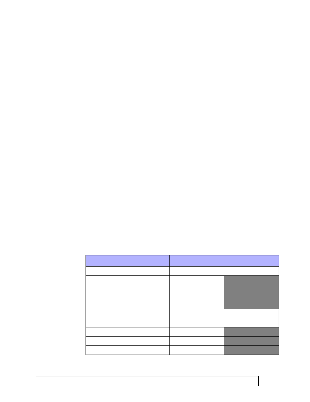
SSC, HTC, and SCLP Ports
. . . . . . . . . . . . . . . . . . . . . . . . . . . . . . . . . . . . . . . . . . . . . . . . . . . . . .
SSC Port Installation
SSC port installation is performed following card installation. Make sure
the PPM card is installed before attempting to install ports.
Use the Install Port command to add ports to the configuration database
and make them operational. Use the Query Port command to display an
installed port’s configuration. Use the Modify Port command to change
the port’s configuration settings.
The general port installation procedure is provided below . An example of
port installation, Example 5-1, is shown after the procedure. All of these
examples assume the operator has already logged in to the Operator
Interface. Following the examples are descriptions of the modifiable
parameters.
To install an SSC port on a PPM module:
1. Use the menu path or expert-mode command shown below to begin
the Install Port command.
Menu Path: CONFIGURATION/INSTALL/PORT
Expert Mode: Install Port
2. The OI prompts for the port ID (the node, card, and port on the card).
Enter the port ID.
The OI also provides the option of copying the configuration of an
installed port. Use this option when installing multiple ports with
identical configurations.
3. Enter the information shown in Table 5-1 for both the origination
port and the answer port on the appropriate nodes:
Table 5-1 Port Parameters for SSC Channels
Parameter Origination Port Answer Port
Orig/Ans Mode ORIG-ONLY ANS-ONLY
Destination Port Device ID for the
answer port
Call/Preempt Priority 15/15
Secondary Call/Preempt Priority1 15/15
Port Type SSC
Port Speed 8000, 16000, or 64000
Time-of-Day Restrictions NONE
Routing Options DON’T CARE
Selected Path2 NONE
Promina 800 Installation and Maintenance Promina Series 5 - 5

. . . . . . . . . . . . . . . . . . . . . . . . . . . . . . . . . . . . . . . . . . . . . . . . . . . . . .
SSC, HTC, and SCLP Ports
Table 5-1 Port Parameters for SSC Channels
Parameter Origination Port Answer Port
Data Flow Direction TWO WAY CALL
Selected Path Required2 NO
IP Only YES (to restrict the channel only to IP traf fic
between these two endpoint nodes)
NO (to allow both SCLP and IP traffic;
neighbor nodes only)
1. Secondary Call/Preempt Priority are available only on nodes running software Release
2.x1 or greater.
2. A selected path must be specified for SSC channels that are configured for IP traffic only.
4. After entering all parameters, enter YES to confirm that the
parameters are correct. The port is then installed and immediately
activated. When both ports are installed, the SSC channel is
established.
5. Confirm that all port parameters and the destination port ID are
correct, then press the Return key to install the port. The OI displays
the configuration for the port.
Example 5-1 PPM SSC Port Installation
ins po,n87c5p1
Do you want to specify any port filters? [NO]
YES or NO =
Port N87C5P1 is type ‘PPM’.
Do you want to install this port? [YES]
YES or NO =
Do you want to copy the configuration of an existing port? [NO]
YES or NO =
*** PPM Port N87C5P1 Configuration Parameters ***
[ 0] Orig/Ans Mode = ANS-ONLY
[ 3] Port Type = SSC
[ 4] Port Speed = 16000 BPS
[10] IP Only = NO
Enter parameter index (or hit RETURN to continue)
PARAMETER INDEX = 0
*** Originate/Answer Modes ***
[ 0]* ANS-ONLY
[ 1] ORIG-ONLY
NOTE: ‘*’ Marks Default Selection.
Enter Originate/Answer Mode for Port N87C5P1
5 - 6 Promina Series Promina 800 Installation and Maintenance

SSC, HTC, and SCLP Ports
. . . . . . . . . . . . . . . . . . . . . . . . . . . . . . . . . . . . . . . . . . . . . . . . . . . . . .
Orig/Ans Mode = 1
Enter Destination Port
Destination Port ID = n160c0p0
*** PPM Port N87C5P1 Configuration Parameters ***
[ 0] Orig/Ans Mode = ORIG-ONLY
[ 1] Destination Port = n160c0p0
[ 2] Call/Preempt Priority (Call= 7; Preempt= 0 )
[ 3] Secondary Call/Prempt Priority (Call= 7; Preempt= 0)
[ 4] Port type = SSC
[ 5] Port Speed = 16000 bps
[ 7] Routing Options(TER=DON'T CARE;ENC=DON'T CARE;FIB=DON'T CARE;
[ 8] Primary Selected Path = NONE
[10] Selected Path Required = YES
[11] IP Only = NO
[14] Max Link Cost = 0
[15] Secondary Selected Path = NONE
[16] Primary Selected Gateway = NONE
[17] Secondary Selected Gateway = NONE
[18] Gateway Required = NO
Enter parameter index (or hit RETURN to continue)
PARAMETER INDEX =
ATM=DON'T CARE; SCLX=DON'T CARE)
Are all parameters correct? [YES]
YES OR NO =
*** PPM Port N87C5P1 Has Been Installed.
*** Command Complete ***
SSC Port
Parameters
This section describes SSC port parameters and their settings. Port
parameters are displayed whenever a port is installed, queried, or
modified. Some parameters apply only to specific port configurations.
For example, if the port is set as an answer-only port, specific parameters
for originating ports are not displayed.
The modifiable parameters and their descriptions follow.
Note: If configuring the port parameter Maximum Link Cost Routing, the
value range is 0 (lowest) through 1023 (highest). T he defa ult is 0 ( no limit) . Fo r
a given call, if the call attempts to traverse to a set of links whose costs exceed
the origination port or port bundle’s maximum link cost value, the call will be
prevented from taking that path and rejected on a call by call basis. For
interdomain calls, the cumulative link cost is reset upon entering a transit and/or
destination domain. This means the cumulative link cost is bounded on a per
domain basis for interdomain calls.
Promina 800 Installation and Maintenance Promina Series 5 - 7

. . . . . . . . . . . . . . . . . . . . . . . . . . . . . . . . . . . . . . . . . . . . . . . . . . . . . .
SSC, HTC, and SCLP Ports
[0] Orig/Ans Mode
The options are Ans-only (default) and Orig-only.
This parameter allows the user to specify whether the port can answer
calls (only) or originate calls (only).
[1] Destination Port
This parameter is required only for originate-only ports.
The value is the port ID for the destination port that communicates with
the origination port.
For permanent calls, when the same begin and end time is specified, the
call is torn down and replaced every day at that time. This technique can
be used to optimize the path used. The call will not be torn down when it
is already on an optimal path.
[2] Call/Preempt Priority
These parameter values apply only to originate-only ports.
The range for Call Priority is 0 (lowest) through 15 (highest). The default
is 7. The range for Preempt Priority is 0 (lowest) through 15 (highest).
The default is 0.
Although they appear as one item, these are two independent parameters.
They work together to determine which call is placed or reconnected.
Call priority determines the order in which a call originating from this
port is reconnected when the port is interrupted for any reason. A port
with a high call priority is reconnected before ports of lower call priority,
but after ports of higher call priority. When all ports have the same call
priority, there is no particular order for reconnection.
Call priority is also used to determine whether a call originating on a port
can be preempted when there is insufficient bandwidth on the link to
handle all calls. Call priority and preempt priority work together in
making this determination.
Preempt priority is used when there is not enough bandwidth to complete
a call. The preempt priority value assigned to the call is compared to the
call priority value assigned to other calls on the link to determine which
calls should be preempted. Calls having a call priority value lower than
the value of the preempt priority call are preempted. The preempted call
is placed when enough bandwidth is recovered.
To prevent certain calls originating on other ports from being preempted,
assign them a call priority that is higher than the value of the preempt
priority . Although preempt priority allows the call to obtain bandwidth, it
5 - 8 Promina Series Promina 800 Installation and Maintenance

SSC, HTC, and SCLP Ports
. . . . . . . . . . . . . . . . . . . . . . . . . . . . . . . . . . . . . . . . . . . . . . . . . . . . . .
does not mean that the call will be completed when the destination port is
busy.
Permanent calls are attempted continually regardless of any external
activation. (A path through the network is dedicated between origination
and destination ports.) Demand calls are assigned bandwidth when the
port goes off-hook and then unassigned when the port goes on-hook.
[3] Secondary Call/Preempt Priority
The range for Secondary Call Priority is 0 (lowest) through 15 (highest).
The default is 7. The range for Secondary Preempt Priority is 0 (lowest)
through 15 (highest). The default is 0.
This parameter provides a secondary call and preempt priority to be used
if the optimal path is not available. If the call tries to build an non-optimal
path, and it tries to preempt other calls on the non-optimal path, then
specified values for secondary call and secondary preempt priority are
used for the call.
[4] Port Type
The value is SSC (default).
For an SSC port the Port Type parameter should be set to: SSC ONLY.
[5] Port Speed
The options are 8, 16 (default), or 64.
The SCC Port Speed parameter can be set to 8, 16, or 64 kbps.
[7] Routing Options
The options are Don’t Care (default), Prefer Not, Preferred, and
Required.
This parameter specifies the routing requirements for terrestrial routing,
encryption routing, ATM routing, SCLX routing, and fiber routing.
Use the routing options parameter to specify the routing method for a
specific application. For example, selecting Fiber can indicate any
operator-defined routing method.
• Don’t Care—Specifies that any available path is used.
• Prefer Not—Specifies that certain paths are used when no other paths
are available. The call is not blocked.
• Preferred—Specifies that certain paths are used first. When those
paths are not available, any path is used. The call is not blocked.
Promina 800 Installation and Maintenance Promina Series 5 - 9

. . . . . . . . . . . . . . . . . . . . . . . . . . . . . . . . . . . . . . . . . . . . . . . . . . . . . .
SSC, HTC, and SCLP Ports
• Required—Specifies that only certain paths can be used. When those
paths are not available, the call is blocked.
[8] Primary Selected Path
Value is None or the selected path.
This parameter allows the user to override the system and specify the path
the call takes through the network. This provides for full end-to-end
management of the call path from the originating node, through the transit
and destination domains, all the way to the destination node. When
creating a path, confirm that it meets the port’s routing attributes. Up to
255 selected paths can be created. Only one path can be specified per
port, but specified paths can be shared among ports.
Up to 12 node IDs, including intermediate nodes and the destination
node, can be specified in a selected path. When specifying more than one
node, separate the node IDs with a comma. The same node cannot be
specified more than once. The default setting for this parameter is None.
After a path is created, it is placed in the path select table, where it can be
queried or deleted. When a path is deleted from the path select table, all
ports using that path are changed to None.
When no path is specified or the selected path is unavailable, the system
determines the best path.
[10] Selected Path Required
The values are No (default) or Yes.
This parameter specifies whether the use of the Selected Path is required
or not. If Yes is selected, calls can be routed only via the Selected Path.
If the Selected Path is not available, then the call will not be built, but the
system will retry the call as set in the Call Processing Parameters when
the node was configured. (Refer to the Node Management manual for
additional information on call retries.)
When the IP Only parameter is set to Yes, this parameter is always set to
Yes.
[11] IP Only
The options are No (default) or Yes.
The IP Only parameter can be set to:
• Yes—Restricts the port to IP packets only
• No—Allows IP and NON-IP Packets signals
5 - 10 Promina Series Promina 800 Installation and Maintenance

SSC, HTC, and SCLP Ports
. . . . . . . . . . . . . . . . . . . . . . . . . . . . . . . . . . . . . . . . . . . . . . . . . . . . . .
[14] Max Link Cost
Value range is 0 (default) to 1023.
This parameter specifies the maximum link cost to be used when placing
this port circuit.
[15] Secondary Selected Path
Value is None or the selected path.
This parameter specifies a secondary call path; see [8] Primary Selected
Path on page 5-10.
[16] Primary Selected Gateway
Values are: 0 through 250; 0 is NONE (default).
This parameter specifies a primary gateway node which is referred to as
the Outbound Gateway (OBGW) node. The call will try to use the newly
specified OBGW node.
[17] Secondary Selected Gateway
Values are: 0 through 250; 0 is NONE (default).
This parameter specifies a secondary gateway node (for backup) which is
referred to as the Outbound Gateway (OBGW) node. The call will try to
use this secondary specified OBGW if the primary selected gateway is
unavailable.
[18] Gateway Required
Values are: Yes or No (default)
This parameter specifies that the specified gateway node(s) is/are
required.
Promina 800 Installation and Maintenance Promina Series 5 - 11

. . . . . . . . . . . . . . . . . . . . . . . . . . . . . . . . . . . . . . . . . . . . . . . . . . . . . .
SSC, HTC, and SCLP Ports
HTC Port Installation
HTC port installation is performed following card installation. Make sure
the nodal controller (processor) card is installed before attempting to
install ports.
The intended connection for the HTC port is to a CX VBR Port bundle.
This configuration allows a Panavue workstation to connect to a Promina
node via an ATM VC.
Only one HTC port can be configured per nodal controller (processor)
card.
The parameters for the PPM are PLM are the same, and the same port
configuration procedures apply to each. Use the Install Port command to
add ports to the configuration database and make them operational. Use
the Query Port command to display an installed port’s configuration.
Use the Modify Port command to change the port’s configuration
settings. PPM and PLM cards have port parameters that can be modified.
The general port installation procedure is provided below. An example of
port installation, Example 5-2, is shown after the procedure. All of these
examples assume the operator has already logged in to the Operator
Interface. Following the examples are descriptions of the modifiable
parameters.
To install an HTC port on a PPM:
1. Use the menu path or expert-mode command shown below to begin
the Install Port command.
Menu Path: CONFIGURATION/INSTALL/PORT
Expert Mode: Install Port
2. The OI prompts for the port ID (the node, card, and port on the card).
Enter the port ID.
The OI also provides the option of copying the configuration of an
installed port. Use this option when installing multiple ports with
identical configurations.
3. Enter the information shown in Table 5-2 for both the origination
port and the answer port on the appropriate nodes:
5 - 12 Promina Series Promina 800 Installation and Maintenance

SSC, HTC, and SCLP Ports
. . . . . . . . . . . . . . . . . . . . . . . . . . . . . . . . . . . . . . . . . . . . . . . . . . . . . .
Table 5-2 Port Parameters for HTC Channels
Parameter Origination Port Answer Port
Orig/Ans Mode ORIG-ONLY ANS-ONLY
Destination Port Device ID for the
answer port
Call/Preempt Priority 15/15
Secondary Call/Preempt Priority1
Port Type HTC
Port Speed Supported speeds are 64000, 128000,
Time-of-Day Restrictions NONE
Routing Options DON’T CARE
Selected Path2
Selected Path Required2 NO
IP The IP address associated with the HTC port.
Master only: YES
1. Secondary Call/Preempt Priority are available only on nodes running software Release
2.x1 or greater.
2. A selected path must be specified for SSC channels that are configured for IP traffic only.
15/15
192000, and 256000 bps.
NONE
4. After entering all parameters, enter YES to confirm that the
parameters are correct. The port is then installed and immediately
activated. When both ports are installed, the HTC channel is
established.
5. Confirm that all port parameters and the destination port ID are
correct, then press the Return key to install the port. The OI displays
the configuration for the port.
Promina 800 Installation and Maintenance Promina Series 5 - 13

. . . . . . . . . . . . . . . . . . . . . . . . . . . . . . . . . . . . . . . . . . . . . . . . . . . . . .
SSC, HTC, and SCLP Ports
Example 5-2 PPM HTC Port Installation
Enter 'NORMAL' to return to normal command mode.
Enter command [DELETE PORT]
< ins po,c12p0/y
Port N168C12P0 is type 'PPM'.
Do you want to install this port? [YES]
YES OR NO =
Do you want to copy the configuration of an existing port? [NO]
YES OR NO =
*** PPM Port N168C12P0 Configuration Parameters ***
[ 0] Orig/Ans Mode = ANS-ONLY
[ 4] Port Type = SSC
[ 5] Port Speed = 16000 bps
[11] IP Only = NO
Enter parameter index (or hit RETURN to continue)
PARAMETER INDEX = 4
*** HTC port must be ORIG ONLY ***
Enter destination bundle
DESTINATION BUNDLE ID = N168C28B0
*** PPM Port N168C12P0 Configuration Parameters ***
[ 0] Orig/Ans Mode = ORIG-ONLY (Dest Bundle is ANS-ONLY)
[ 1] Destination Bundle = N168C28B0 (Dest Bundle is CX)
[ 2] Call/Preempt Priority (Call= 7; Preempt= 0 )
[ 3] Sec Call/Preempt Priority (Call= 7; Preempt= 0 )
[ 4] Port Type = HTC
[ 5] Port Speed = 64000 bps (Dest Bundle is 256000)
[ 7] Routing Options (TER=DON'T CARE; ENC=DON'T CARE; FIB=DON'T CARE)
[12] IP Address = 0.0.0.0
[13] Master Only = NO
Enter parameter index (or hit RETURN to continue)
PARAMETER INDEX = 12
Enter IP Addr:
IP ADDRESS = 192.168.2.2
*** PPM Port N168C12P0 Configuration Parameters ***
[ 0] Orig/Ans Mode = ORIG-ONLY (Dest Bundle is ANS-ONLY)
[ 1] Destination Bundle = N168C28B0 (Dest Bundle is CX)
[ 2] Call/Preempt Priority (Call= 7; Preempt= 0 )
[ 3] Sec Call/Preempt Priority (Call= 7; Preempt= 0 )
[ 4] Port Type = HTC
[ 5] Port Speed = 64000 bps (Dest Bundle is 256000)
[ 7] Routing Options (TER=DON'T CARE; ENC=DON'T CARE; FIB=DON'T CARE)
[12] IP Address = 192.168.2.2
[13] Master Only = NO
Enter parameter index (or hit RETURN to continue)
5 - 14 Promina Series Promina 800 Installation and Maintenance

SSC, HTC, and SCLP Ports
. . . . . . . . . . . . . . . . . . . . . . . . . . . . . . . . . . . . . . . . . . . . . . . . . . . . . .
PARAMETER INDEX = 5
Valid speeds for HTC Ports are:
64000 128000 192000 256000
Enter Port Speed (BPS) for port N168C12P0 [64000]
Port Speed (BPS) = 256000
*** PPM Port N168C12P0 Configuration Parameters ***
[ 0] Orig/Ans Mode = ORIG-ONLY (Dest Bundle is ANS-ONLY)
[ 1] Destination Bundle = N168C28B0 (Dest Bundle is CX)
[ 2] Call/Preempt Priority (Call= 7; Preempt= 0 )
[ 3] Sec Call/Preempt Priority (Call= 7; Preempt= 0 )
[ 4] Port Type = HTC
[ 5] Port Speed = 256000 bps (Dest Bundle is 256000)
[ 7] Routing Options (TER=DON'T CARE; ENC=DON'T CARE; FIB=DON'T CARE)
[12] IP Address = 192.168.2.2
[13] Master Only = NO
Enter parameter index (or hit RETURN to continue)
PARAMETER INDEX = 13
*** PPM Port N168C12P0 Configuration Parameters ***
[ 0] Orig/Ans Mode = ORIG-ONLY (Dest Bundle is ANS-ONLY)
[ 1] Destination Bundle = N168C28B0 (Dest Bundle is CX)
[ 2] Call/Preempt Priority (Call= 7; Preempt= 0 )
[ 3] Sec Call/Preempt Priority (Call= 7; Preempt= 0 )
[ 4] Port Type = HTC
[ 5] Port Speed = 256000 bps (Dest Bundle is 256000)
[ 7] Routing Options (TER=DON'T CARE; ENC=DON'T CARE; FIB=DON'T CARE)
[12] IP Address = 192.168.2.2
[13] Master Only = YES
Enter parameter index (or hit RETURN to continue)
PARAMETER INDEX =
Are all parameters correct? [YES]
YES OR NO =
*** PPM Port N168C12P0 has been INSTALLED.
*** PPM Port N168C12P0 has been ACTIVATED.
*** Command Complete ***
HTC Port
Parameters
This section describes HTC port parameters and their settings. Port
parameters are displayed whenever a port is installed, queried, or
modified. Some parameters apply only to specific port configurations.
For example, if the port is set as an answer-only port, specific parameters
for originating ports are not displayed.
The modifiable parameters and their descriptions follow.
Promina 800 Installation and Maintenance Promina Series 5 - 15

. . . . . . . . . . . . . . . . . . . . . . . . . . . . . . . . . . . . . . . . . . . . . . . . . . . . . .
SSC, HTC, and SCLP Ports
Note: If configuring the port parameter Maximum Link Cost Routing, the
value range is 0 (lowest) through 1023 (highest). T he defa ult is 0 ( no limit) . Fo r
a given call, if the call attempts to traverse to a set of links whose costs exceed
the origination port or port bundle’s maximum link cost value, the call will be
prevented from taking that path and rejected on a call by call basis. For
interdomain calls, the cumulative link cost is reset upon entering a transit and/or
destination domain. This means the cumulative link cost is bounded on a per
domain basis for interdomain calls.
[0] Orig/Ans Mode
The option is Orig-only.
This parameter allows the user to specify that the port can originate calls
(only).
[1] Destination Port
This parameter is required only for originate-only ports.
The value is the port ID for the destination port that communicates with
the origination port.
Note: When configuring an HTC port, the destination port must be on a CX
module.
[2] Call/Preempt Priority
These parameter values apply only to originate-only ports.
The range for Call Priority is 0 (lowest) through 15 (highest). The default
is 7. The range for Preempt Priority is 0 (lowest) through 15 (highest).
The default is 0.
For the complete description see [2] Call/Preempt Priority on page 5-8.
[3] Secondary Call/Preempt Priority
The range for Secondary Call Priority is 0 (lowest) through 15 (highest).
The default is 7. The range for Secondary Preempt Priority is 0 (lowest)
through 15 (highest). The default is 0.
For more information see [3] Secondary Call/Preempt Priority on page
5-9.
[4] Port Type
The value is HTC.
5 - 16 Promina Series Promina 800 Installation and Maintenance

SSC, HTC, and SCLP Ports
. . . . . . . . . . . . . . . . . . . . . . . . . . . . . . . . . . . . . . . . . . . . . . . . . . . . . .
HTC is the mode which connects the nodal controller (processor) to the
HDLC port on a CX module. In addition, this parameter allows you to
specify a port type of SSC.
[5] Port Speed
Supported speed are 64000, 128000, 192000, and 256000 bps.
Note: A second TBus phase allocation will accommodate the HTC port
bandwidth.
[7] Routing Options
The options are Don’t Care (default), Prefer Not, Preferred, and
Required.
This parameter specifies the routing requirements for terrestrial routing,
encryption routing, ATM routing, and fiber routing.
For a description of the routing options parameter values see [7] Routing
Options on page 5-9.
[8] Selected Path
The values are None (default) or the applicable node IDs.
Up to 12 node IDs, including intermediate nodes and the destination
node, can be specified in a selected path. When specifying more than one
node, separate the node IDs with a comma. The same node cannot be
specified more than once.
[10] Selected Path Required
The values are No (default) or Yes.
This parameter specifies whether the use of the Selected Path is required
or not. If Yes is selected, calls can be routed only via the Selected Path.
If the Selected Path is not available, then the call will not be built, but the
system will retry the call as set in the Call Processing Parameters when
the node was configured. (Refer to the Node Management manual for
additional information on call retries.)
[12] IP
The IP address associated with the HTC port. This is the address that will
be used as the "gateway" address when adding an IPA route. Once the
IPA is either defined or referred, the IP Gateway needs to be installed
before an HTC port will allow IP Connectivity to the Promina node.
Promina 800 Installation and Maintenance Promina Series 5 - 17

. . . . . . . . . . . . . . . . . . . . . . . . . . . . . . . . . . . . . . . . . . . . . . . . . . . . . .
SSC, HTC, and SCLP Ports
[13] Master-only
This field is only visible when the port is configured for ORIG-ONLY. If
set to YES, the port will only attempt to build if it is on a Master
processor.
• HTC port is intended to facilitate SNMP management through
Panavue workstation at a remote location with ATM connectivity.
• A single connection is allowed between a Panavue workstation and a
Promina processor.
Redundancy. When a processor fails and redundant processors are
available the node recovers. The HTC port configuration is processor
module-specific.
You can use the Master-only parameter to configure a recoverable HTC
port configuration (where only one PPM module will activate its HTC
port).
To use the Master-only parameter for redundancy, follow these steps:
1. Configure HTC ports on all processors as ORIG-ONLY with the
destination port being the same CX VBR port bundle.
2. Set the Master-only parameter to YES.
3. Make sure that the ports in CX VBR port bundle are ANS-only.
When the Master-only parameter is set to YES, the HTC port will only
build if that port resides on a card configured as a master CPU.
In the node, one and only one HTC port call can be built. This one call
will always be built on the master processor . When redun dant processors
are available and the master fails, the new master brings the HTC call
back up on the same CX bundle.
5 - 18 Promina Series Promina 800 Installation and Maintenance

SSC, HTC, and SCLP Ports
. . . . . . . . . . . . . . . . . . . . . . . . . . . . . . . . . . . . . . . . . . . . . . . . . . . . . .
SCLP/SSC Port Query Displays
After ports are installed, the operator can query the port through the
Operator Interface to display the port’s current configuration. Example
5-3 shows the configuration display for SSC ports when the port and the
card is queried. Descriptions of the configuration fields are provided after
the example.
PPM, PLM,
and IPLM
Configurations
Example 5-3 SSC Configuration Display
< q port, c0p0/d
*** PLM PORT N11C0P0 CONFIGURATION (DEST PORT IS PORT N14C0P0) ***
N11C0P0 N14C0P0 N11C0P0 N14C0P0
CARD TYPE: PLM PLM SLOT TYPE: PLM PLM
DBCARD STATUS: ACTIVE ACTIVE DB PORT STATUS: ACTIVE ACTIVE
ORIG/ANS MODE: ORIG-ONLY ANS-ONLY DEST PORT: N14C0P0
PORT SPEED: 1600 16000
PORT TYPE: SSC SSC
IP ONLY: YES YES
CALL PRIORITY: 14 PREEMPT PRTY: 10
Sec CALL PRIORITY: 9 Sec PREEMPT PRTY: 5
TERR ROUTING: DON'T CARE TOD RESTRICT: NONE
ENCRY ROUTING: DON'T CARE
FIBER ROUTING: DON'T CARE
ATM ROUTING: DON’T CARE
SCLX ROUTING: DON’T CARE
SELECTED PATH: (INDEX 1) 11-14
PATH REQUIRED: NO
ACTUAL PATH: 11-14 (OP)
DATA FLOW DIRECTION: TWO WAY CALL
*** PLM PORT N11C0P0 STATUS ***
CALL STATE: CALL IN PROGRESS LAST DISCONNECT: NONE
LINK STATUS: UP for 15467 seconds to N86C3P1
PKTS RECVD: 44 (FOR LAST 731 SECONDS)
PKTS SENT: 28 (FOR LAST 731 SECONDS)
*** HIT RETURN TO CONTINUE (ESCAPE TO QUIT) ***
*** COMMAND COMPLETE ***
< q car, c4/d
** PPM Port N64C4P0 Configuration (Dest Port is Port N24C7P1) ***
N64C4P0 N24C7P1 N64C4P0 N24C7P1
Card Type: PPM PPM Slot Type: PPM PPM
DBCard Status: ACTIVE ACTIVE DB Port Status: ACTIVE ACTIVE
Orig/Ans Mode: ORIG-ONLY ANS-ONLY Dest Port: N24C7P1
Port Speed: 64000 64000
Port Type: SSC SSC
IP Only: NO NO
Call Priority: 7 Preempt Prty: 0
Sec Call Prty: 7 Sec Prmt Prty: 0
Promina 800 Installation and Maintenance Promina Series 5 - 19

. . . . . . . . . . . . . . . . . . . . . . . . . . . . . . . . . . . . . . . . . . . . . . . . . . . . . .
SSC, HTC, and SCLP Ports
Terr Routing: DON'T CARE
Encry Routing: DON'T CARE
Fiber Routing: DON'T CARE
ATM Routing: DON'T CARE
SCLX Routing: DON'T CARE Max Link Cost: 0
Pri Sel Path: (Index 1) 64,24
Sec Sel Path: NONE
Path Required: YES
Actual Path: 64-24 (OP)
*** PPM Port N64C4P0 Status (Other End is N24C7P1) ***
Call State: Up/Up Last Disconnect: NONE
Pkts Recvd: 7 (for last 4 seconds)
Pkts Sent: 7 (for last 4 seconds)
Port Configuration
Descriptions
The following list describes the fields of the port configuration display.
Since the configuration display does not have numbered fields, the fields
are described here in alphabetical order.
ATM Routing
See [7] Routing Options on page 5-9.
Call Priority
Refer to [2] Call/Preempt Priority on page 5-8.
Call State
Indicates the current condition of the call when the port is queried. Valid
states are as follows:
• Idle/Down—When port is waiting to originate or answer a call.
• Verify/Down—When originating side is waiting verification of
destination parameter.
• Placing/Down—When originating side is building call to destination.
Transitory.
• Up/Down—When call is up but link is down.
• Up/Out Align—When call is up but link is out of alignment.
• Up/In Align—When call is up but link is in alignment.
• Up/Proving—When call is up but link is proving stability.
• Up/Align Up—When call is up and link has just proved aligned.
• Up/Up—When call is up and the link is up.
5 - 20 Promina Series Promina 800 Installation and Maintenance
 Loading...