

NESTOR MARTIN H15, TQH35, H25, H35, H45 Instruction Manual
...
1
Models
H15 ALSO KNOWN AS S15 AND C15
H45 ALSO KNOWN AS S45 AND C45
RH35 ALSO KNOW AS FH35
H25 ALSO KNOWN AS S25 AND C25
H35 ALSO KNOWN AS S35 AND C35
Models
H15 ALSO KNOWN AS S15, S15+ AND C15
H45 ALSO KNOWN AS S45, S45+ AND C45
TQH35 ALSO KNOW AS FH35 AND RH35
H25 ALSO KNOWN AS S25, S25+ AND C25
H35 ALSO KNOWN AS S35, S35+ AND C35
TQH15
INSTRUCTIONS
Balanced flue
Gas
Industrias Hergóm S.A.
Soto de la Marina.
Cantabria. España

2
Content
1. General Notes 3
2. User instructions. 4
2.1 First Time of Operation 4
2.2 Remote Control Overview 4
2.3 Batteries 5
2.4 Replacing the batteries 5
2.5 Setting the Transmitter code 5
2.6 To Ignite the appliance 5
2.7 To Turn the appliance OFF 6
2.8 Adjusting the Flame setting 6
2.9 N/A 6
2.10 Setting °C/24 hour or °F/12 hour clock 6
2.11 Setting the Time 6
2.12 Cleaning and Maintenance 6
3. Installation instructions. 7
3.1 Gas Connection 7
3.2 Ventilation 7
3.3 Installation 7
3.4 Flue Connection 8
3.5 Fuel Bed Arrangements 13
3.6 Dimensions 24
3.7 Commissioning the appliance 30
4. Servicing 32
4.1 Cleaning the Ceramics 32
4.2 Servicing the Burners 32
4.3 Spare parts 33
5. Technical Information 34
5.1 Countries of Use 34
5.2 Technical Data 36

3
General Notes
This gas appliance is a High Efficiency, Balanced Flue Live Fuel Effect appliance. It provides radiant and
convected heat using the latest burner technology.
Before Installation, check that the local distribution conditions, nature of the gas and pressure, and adjustment of
the appliance are compatible.
This appliance is intended for use on a gas installation with a governed meter.
This Gas Installation may only be installed by a registered professional competent person (Gas Safe
installer in the UK). The installation must adhere to the requirements of the local and national Building
regulations and national standards. The installation manual must also be followed.
Ensure that the Flue Terminal is not in any way obstructed and is clear of vegetation, i.e. trees, shrubs etc. and
that no objects are leant against the terminal or guard.
Always clean the Window Panel before the fire is ignited. Any finger prints must be removed, as these will be
burnt into the glass and will be un-removable.
WARNING : Do not operate this appliance if the glass panel has been broken (or cracked), removed or is open.
The appliance is designed to fit numerous installation situations as listed in these installation instructions.
However only flue approved by Nestor Martin for this appliance may be used.
This appliance is a balanced flue product and is room sealed and as such requires no additional ventilation for
operation. However an adequate supply of fresh air to maintain temperatures and a comfortable environment is
recommended.
This appliance is designed as a heating appliance, and as such will get very hot in operation, all surfaces (except
the controls and access door) are considered to be working surfaces and as such should not be touched. The
front windows and surrounds are not considered to be fully secure guards against accidental contact. It is
recommended that an approved fire screen be used if children, the elderly or persons with limited mobility are to
be present in the same area.
Do not place curtains, laundry, furniture etc. within a safe distance of 600mm of this appliance.
Do not attempt to burn rubbish on this appliance.
If this appliance is extinguished, on purpose or other, no attempt to relight should be made within 3 minutes.
4
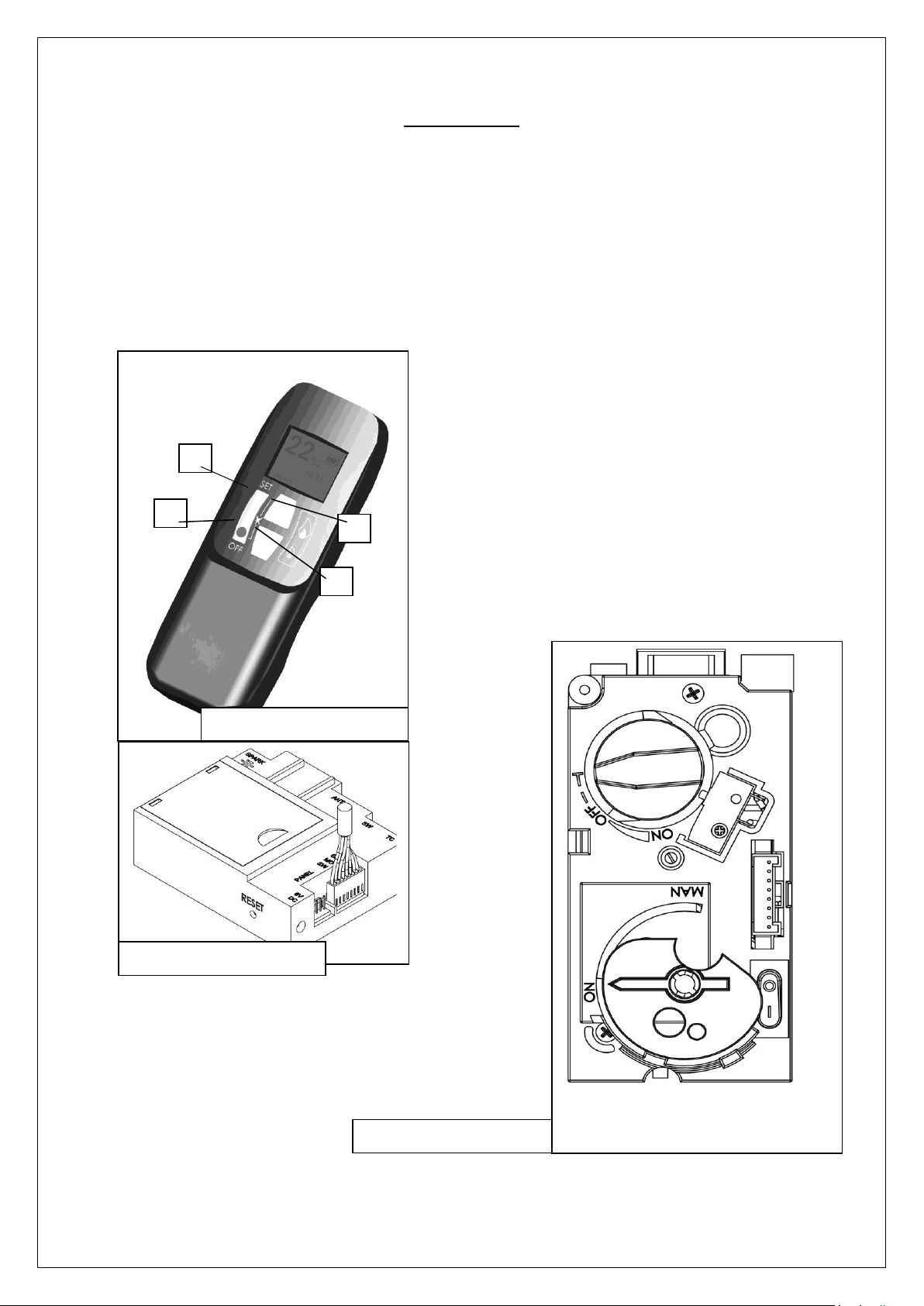
fig. 1.1 Remote Handset
fig. 1.2 Remote Receiver
fig. 1.3 Gas Control Valve
User instructions
2. User instructions.
2.1 First Time of Operation
Before igniting the appliance, ensure that all packaging, safety stickers and any protective wrapping have been
removed, and that the glass has been cleaned, including all fingerprints from the glass.
Ensure that the room is adequately ventilated the first time that the appliance is ignited, we would recommend
opening windows if possible. Run the appliance at full setting for a few hours so that the paint gets an opportunity
to fully cure. During this period it is possible for some fumes and vapours to be given off. We would recommend
keeping children and pets out of the area at this time.
2.2 Remote Control Overview
This Nestor Martin Gas Appliance has been constructed with
an advanced remote control system. This consists of three
main parts; Handset (fig. 1.1), Receiver (fig. 1.2) and Gas
Valve with Manual Override (fig. 1.3). The Gas control valve
and the Receiver are behind the access door. This is also
where the product Data Label is located.

5
User instructions
2.3 Batteries
Remote Handset:
1 x 9V "PP3" Battery, Quality alkaline recommended
Receiver:
4 x 1.5V "AA", Quality alkaline recommended for maximum life.
An alternative AC Mains Adaptor may be used to power the Receiver instead of the 4 AA batteries. Only an AC
Mains Adapter supplied by Nestor Martin may be used. The Mains Adaptor is plugged into the DC 6V socket on
the end of the receiver.
Note - if the AC Mains Adapter is used, remove the 4 AA's from the Receiver, failure to do so could result in
damage and failure of the Receiver. During a period of power outage, the receiver may be unplugged and
batteries returned to the Receiver.
2.4 Replacing the batteries
Handset:
There is a battery level indicator on the display of the handset. When this gets low remove the cover on the rear
of the handset and replace the battery with another 9V PP3 battery.
Receiver:
Three short audible beeps will sound when the appliance is on to indicate that the batteries in the receiver are
getting low.
When the batteries get very low the appliance will be turned off by the remote control. This will fail to happen if
the power supply is interrupted.
To replace the Receiver batteries, slide the cover off of the top of the receiver and use the ribbon to pull the
batteries out. Replace the batteries with new 1.5V AA's, ensuring that the ribbon is located under the batteries
and that the polarity is correct on all 4 batteries.
Never mix new batteries with old, this will result in the new batteries being emptied very quickly.
When the batteries are replaced, it may be necessary to reset the transmitter code, as detailed in the next
section.
2.5 Setting the Transmitter code
Press and hold the RESET button with a sharp object (pen or screwdriver) until you hear two audible beeps. After
the second, longer beep, release the RESET button.
Within the next twenty seconds press the down button (Button D fig 1.1) on the remote handset until you hear an
additional long signal confirming the code is set.
2.6 To Ignite the appliance
Note - If this appliance is extinguished or goes out in use for any reason, wait 3 minutes before attempting to
relight the appliance. The Gas Control Valve has an interlock device which will not allow relighting until the 3
minutes have passed.
To be able to use the Remote control Handset (fig. 1.1), the rocker switch on the Gas Valve, must be turned "ON"
(the "1" position) and the manual Dial set to the "On" position.
- Simultaneously press and hold buttons B & C (Star and Large Flame), until a short acoustic
beep confirms the start sequence has begun; release the buttons.
- Continuing signals confirm the ignition is in process.
- Once pilot ignition is confirmed, there will be gas flow and the main burner will ignite.
- Repeat process if pilot ignition fails.

6
User instructions
2.7 To Turn the appliance OFF
Press the OFF button (Button B fig. 1.1) on the Handset. This will extinguish all Burners including Pilot.
Note:- Repeated presses of the small flame (Button D fig. 1.1) will turn the main burner OFF, but will leave the
Pilot alight.
2.8 Adjusting the Flame setting
To increase the flame height; press the large flame button (Button C fig. 1.1).
To decrease the flame height; press the small flame button (Button D fig. 1.1).
2.9 N/A
N/A
2.10 Setting °C/24 hour or °F/12 hour clock
Simultaneously press OFF and Small Flame buttons (buttons B & D fig. 1.1) until display changes from
Fahrenheit/12 hour clock to Celsius/24 hour clock and vice versa.
2.11 Setting the Time
The display will flash after either:
a. Installing the battery or
b. Simultaneously pressing the Large Flame Button and Small Flame Button (buttons C & D fig. 1.1)
Press the Large Flame button (button C fig. 1.1) to set the hour.
Press the Small Flame button (button D fig. 1.1) to set the minutes.
Press OFF (button B fig. 1.1) to return to standard operating mode or simply wait and it will return to standard
mode after approximately 15 seconds.
2.12 Cleaning and Maintenance
This appliance should be inspected and serviced once a year by a qualified, competent and registered person.
The inspection and maintenance must at least ensure that the appliance is working correctly and safely. It is
advisable to clean the appliance of any dust and debris before regularly during the heating season and especially
if the appliance has not been used for some time. This can be done with a soft brush and a vacuum cleaner or a
damp cloth and if required a non-abrasive cleaning agent. Do not use corrosive or abrasive substances to clean
the appliance.

7
Installation instructions
3. Installation instructions.
Before commencing Installation, confirm that the details on the appliance data plate correspond to the local
distribution conditions, gas type and pressure to which the appliance is to be installed.
Ensure that gas supply and supply pipe is capable of delivering the required volume and pressure of gas and is in
accordance with the rules in force.
3.1 Gas Connection
This appliance has a gas inlet connection of Ø 8mm or Ø 12mm dependant on country of use
3.2 Ventilation
This appliance is a Balanced Flue room sealed appliance, and as such needs no additional ventilation. However
an adequate supply of fresh air to maintain temperatures and a comfortable environment is recommended.
This appliance may be installed in a completely sealed or mechanically ventilated house.
3.3 Appliance Fireplace Installation (INSET)
Determine the position required for the appliance.
Create a gas connection for the appliance in approximately the correct location for the gas controls.
The gas controls are connected to the Burner of the appliance.
Fine adjustment and leveling legs is available via the feet.
Do not make any adjustments to the appliance.
The appliance and Flue system should be fitted with a minimum clearance of 500mm from any combustible
objects or materials; this includes any combustible materials used for the fireplace construction.
As this is a room sealed appliance and the appliance stands on appropriate feet, a hearth is not required for this
appliance.
The Fireplace should be ventilated with openings giving a total free vent area of 200 cm².
A gap of 50mm should be left all round the appliance (applies to non-combustible surfaces only).
3.4 Appliance installation (Models SHC15, SHC45, RH35 and FH35, SHC25, SHC35, TQH15 and TQH35)
3.5 A non-combustible hearth must be used this hearth must be a minimum of 12mm thick, and project a
minimum of 50mm from the base of the appliance in all directions.
3.6 These appliance are not suitable for installation against a combustible wall. A combustible side wall must be a
minimum of 75mm from the appliance. (see page 8)
3.7 These appliances can be installed with an up and out flue (vertical wall - horizontal flue) except TQH15 (only
vertical flue) . Specific terminals are mandatory, see page 9
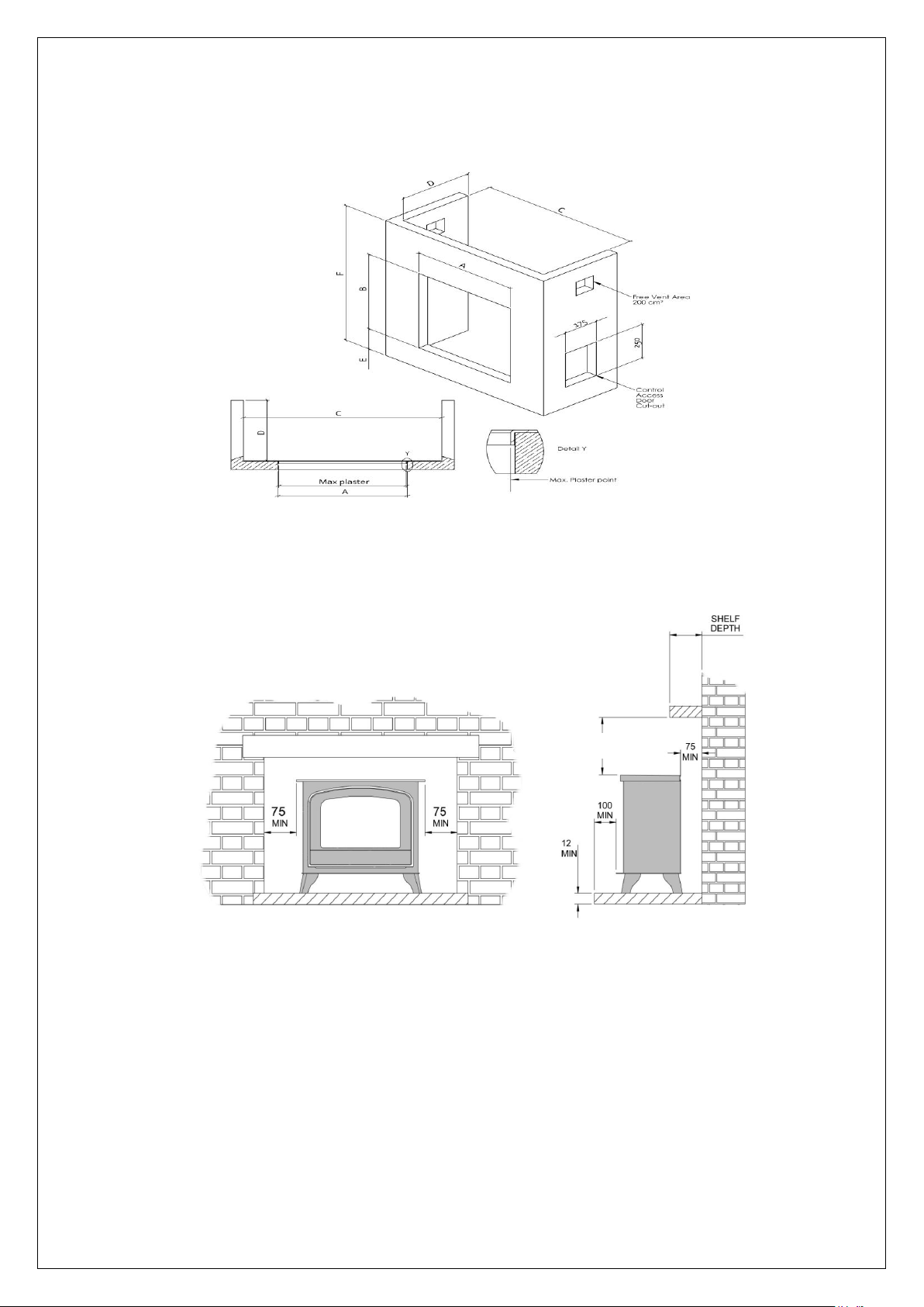
280 min
3.3.1 Building the Fireplace
8
A=550 B=600 C=750 D=400 E=100 F=800
Control access door if required
The stove must be located at least 280mm from any combustible materials.
A combustible shelf may be fitted over the appliance, if in the case of a 150mm or less deep shelf, there is at
least 280mm clearance above the top of the stove. The shelf depth may increase at the same rate as the
increase in clearance; i.e. a shelf depth of 200mm would require a clearance of 330mm.
9
Installation instructions
3.4 Flue Connection
3.4.1 General notes
This appliance may be installed with a roof terminal (C31) or a wall terminal (C11).
This appliance may only be used with Balanced Flue (otherwise known as Concentric Flue) parts as specified by
Nestor Martin. The Nestor Martin specified flue parts have been approved with the appliance. If the appliance is
installed on non- Nestor Martin approved parts, Nestor Martin cannot guarantee or accept and responsibility for
the proper and safe working of the appliance.
The flue system must be constructed from the appliance upwards, with all joints being fully locked and sealed
using the Nestor Martin specified parts.
The certified pipes to use are :
Vertical configuration (roof) :
Pipes US 100/150 mm Metaloterm B.V. with adaptator USAK 2 10 and with the vertical roof
terminal USDVC2 10
- Horizontal configuration (wall) with vertical pipes starting from the appliance :
Pipes US 100/150 mm Metaloterm B.V. with adaptator USAK 2 10 and with the horizontal wall
terminal USDHC2 10
- Horizontal configuration (wall) starting directly from the appliance with horizontal connections :
pipes US 100/150 mm Metaloterm B.V. with adaptator USAK 2 10 and with USDSC 10 (terminal
SNORKEL)
3.4.2 Timber Frame Construction
Whilst it is possible to install room-sealed appliances in timber frame properties, great care needs to be taken to
ensure that the flue assembly does not interfere with the weather proofing qualities of any outer wall which it may
penetrate. Before attempting this work, further details need to be referenced, (e.g. “Gas Installations in Timber
Frame Buildings” from the Gas Safe installer series in the UK).
3.4.3 Carport or Building Extension
Where a flue terminal is sited within a carport or building extension, it should have at least two completely open
and unobstructed sides. The distance between the lowest part of the roof and the top of the terminal should be at
least 600mm.
Note: A covered passageway should not be treated as a carport. Flues should not be sited in a covered
passageway between properties.
3.4.4 Basements, Lightwells and Retaining walls
Flue terminals should not be sited within the confines of a basement area, light well or external space formed by
a retaining wall, unless steps are taken to ensure the products of combustion can disperse safely at all times. It
may be possible to install this Balanced Flue system in such a location provided that it is not sited lower than 1m
from the top level of that area to allow combustion products to disperse safely.
Flue terminals should be sited to ensure total clearance of the combustion products in accordance with the
included information.
10
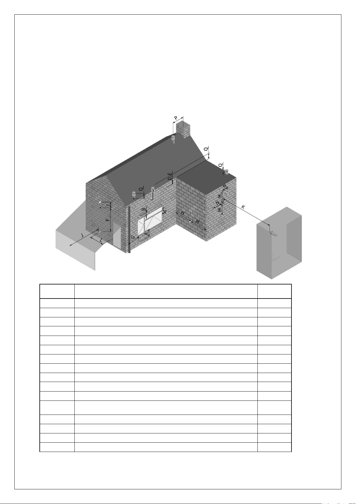
Dimension
Terminal Position
Distance
(mm)
A*
Directly below an opening, air brick, opening window etc.
600
B
Above an opening, air brick, opening window etc.
300
C
Adjacent to an opening, air brick, opening window etc.
400
D
Below gutters, soil pipes or drain pipes
300
E
Below eaves
300
F
Below balconies of car port roof
600
G
From a vertical drain pipe or soil pipe
300
H
From an internal or external corner
600
I
Above ground roof or balcony level
300
J
From a surface facing the terminal
600
K
From a terminal facing the terminal
600
L
From an opening in the car port (e.g. door , window into the
dwelling)
1200
M
Vertically from a terminal on the same wall
1500
N
Horizontally from a terminal on the same wall
300
P
From a vertical structure on the roof
600
Q
Above intersection with roof
150
When the products of combustion are discharged, they should not cause a nuisance to adjoining or adjacent
properties and they should be positioned so that damage cannot occur to other parts of the building. If the outer
wall surface is constructed of combustible material, a non-combustible plate should be fitted behind the terminal
projecting 25mm beyond the external edges of the terminal.
Installation instructions
3.4.5 Terminal Locations.
11
* I addition, the terminal should not be nearer than 300mm to an opening in the building
fabric
formed for the purpose of accommodating a built in element such as a window
frame.
Installation instructions
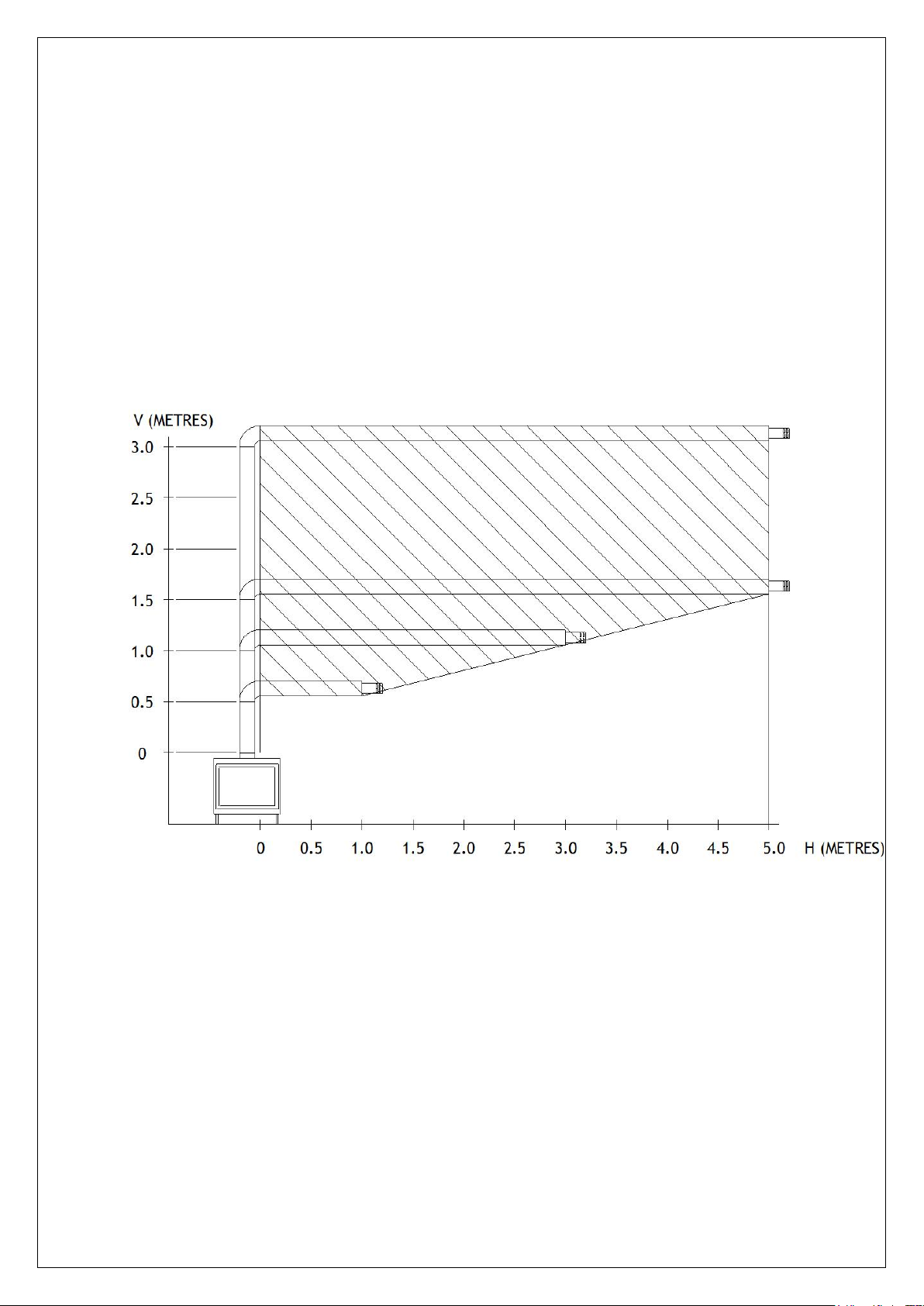
3.4.6 Horizontal Wall Vent Termination type C11
Flue sizing:
: Ø100/150 throughout.
Maximum pipe extension, for outside wall.
Use shaded area to calculate maximum allowable length (H) for the corresponding pipe rise (V).
12
Installation instructions
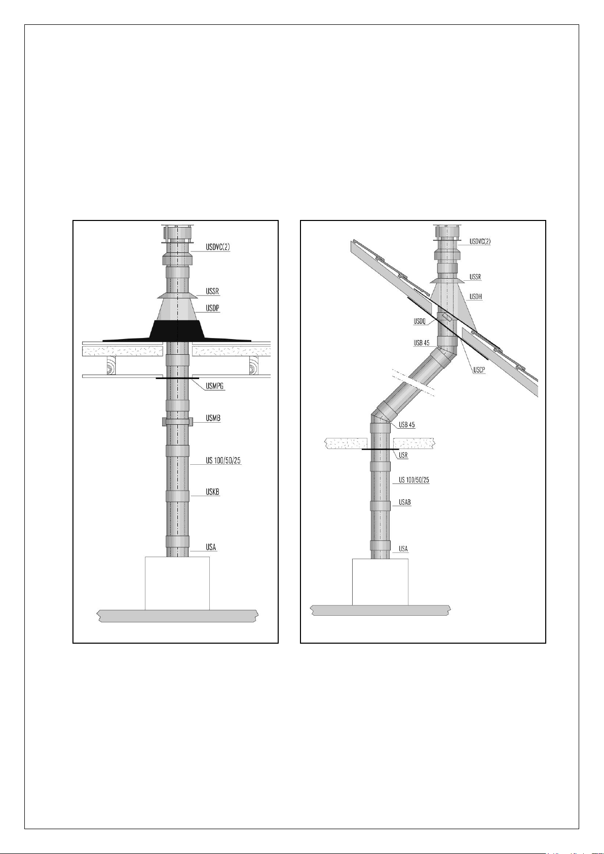
3.4.7 Vertical Roof Vent Termination C31
Flue sizing:
35mm flue restrictor, Ø100/150 Spigot on appliance
When incorporating and horizontal flue runs, these horizontal runs must be less than 0.5 times the
overall flue height.
IMPORTANT
Every 45° bend equivalent to 25cm of Horizontal Flue and every 90° bend equivalent to 50cm of
Horizontal Flue. When you use HORIZONTAL flue situations, then, for every 1m' of HORIZONTAL
you must add 0.5m' of VERTICAL, in addition to the diagram.
 Loading...