

NESTOR MARTIN S33, H33, X33, R33 Operating Instructions Manual
Manufactured by:
Fonderies du Lion Development
11 Rue du Lion
5660 Couvin, Belgium
SAVE THESE INSTRUCTIONS FOR FUTURE REFERENCE
INSTALLATION AND OPERATING INSTRUCTIONS
S33
H33 R33
X33
EPA-CERTIFIED NONCATALYTIC WOODSTOVES
WITH WOODBOX© TECHNOLOGY
S33##1710A

Dear Customer,
We would like to thank you for purchasing a Nestor Martin heating appliance. For over 150 years, we have provided
our customers with high-quality, worry-free products that stand the test of time. We work hard so that you can enjoy
the warmth of your new stove for years to come.
If you have questions that are not covered in this manual, please feel free to contact your local Nestor Martin dealer
for more information.
Rudy Cyris
President
2
Table Of Contents
Page
Safety Notice 3
Product Specifications 3
Installation Guide 4
Dimensions S33 and H33 4
Clearances to Combustibles S33 and H33 4
Dimensions X33 and R33 5
Clearances to Combustibles X33 and R33 5
Floor Protection Requirements 6
Types of Chimneys 6
Chimney Inspection 6
Draft Requirements 7
Chimney Height 7
Standard Installation Procedure 8
Freestanding Installations 8
Above a Fireplace 9
Wall Pass-Throughs 9
Acceptable Types of Connector Pipe 10
The Woodbox Combustion System 11
Air Distribution System 11
Controlling Components 11
The Air Intake Controls 12
Operating Instructions 13
Lighting a Fire 13
Use of the Remote Control 14
Refuelling the Stove 14
Overnight Burning 14
Ash Removal 15
Guidelines for Safe Operation 15
Flue Gas Temperature 15
Unattended Fires 16
In Case of a Chimney Fire 16
Choice of Firewood 17
Maintenance 17
Integrated Airwash System 17
Manual Cleaning of the Glass 17
Cleaning the Stove Body 17
Creosote Formation 18
Summer Shut Down 18
Door Handle Adjustment 19
Ash Pan Door Adjustment 19
Spare Parts 20
Spare Parts, S33 20
Spare Parts, H33 22
Spare Parts, X33 24
Spare Parts, R33 26
Safety Labels 28
Warranty 30

Product Specifications
Flue collar size: 6”
Flue position: top
Max burn rate: 59,000 BTU/hr
EPA output range: 8,600 – 37,300 BTU/hr
Emissions rate: 3.43 g/hr
Heating capacity: 1,100 – 1,500 sq ft
Max. burn time: up to 10 hours
Max log length: 17”
Weight: H33: 346 lbs
S33: 358 lbs
R33: 316 lbs
X33: 316 lbs
Safety Listing
Your appliance has been tested following standards :
US Standard: ANSI/UL 1482
Canadian Standard : CAN/ULC-S627
Tests performed by OMNI-Test Laboratories, Inc., Beaverton, Oregon
This stove meet the US Environmental Protection Agency’s emissions limits for wood heaters.
3
Safety Notice
Please read this entire manual before you install and use your new room heater. Failure to follow instructions may result
in property damage, bodily injury or even death.
If your stove is not properly installed, a house fire may result. For your safety, follow the installation directions. Contact
local building or fire officials about restrictions and installation requirements in your area.
The authority having jurisdiction (such as municipal building department, fire department, fire prevention bureau, etc.)
should be consulted before installation to determine the need to obtain a permit.
ENSURE THAT THIS MANUAL REMAINS WITH THE APPLIANCE AND IS PASSED ON TO THE USER AFTER
INSTALLATION. DO NOT STORE OR USE GASOLINE OR OTHER FLAMMABLE VAPORS AND LIQUIDS IN THE
VICINITY OF THIS APPLIANCE.
WARNING: Improper installation, adjustment, alteration, service or maintenance can cause injury or property
damage. Refer to this manual for assistance or consult a qualified (experienced) installer.
Installation Guide
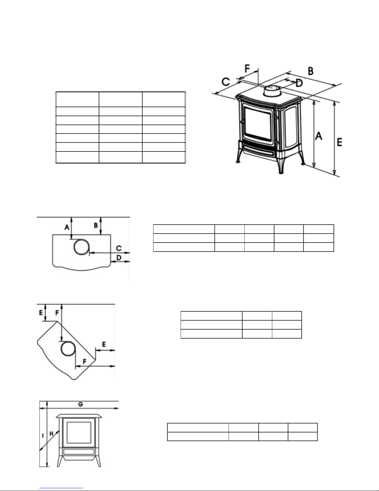
S33 H33
A 30” (751mm) 28” (716mm)
B 25” (631mm) 26” (649mm)
C 16” (395mm) 15” (370mm)
D 6” (150mm) 6” (150mm)
E 32” (816mm) 31” (781mm)
F 5” (113mm) 5” (113mm)
S33 and H33 cast iron models
Dimensions
Clearances to Combustible Materials
Back and side wall clearances
Corner clearances
Alcove clearances
Connector pipe A B C D
Single wall 14” 13” 18” 9”
Double wall 13” 12” 18” 9”
Minimum ceiling height: 30” (unit to ceiling)
Connector pipe E F
Single wall 10½” 19”
Double wall 7” 15½”
Minimum ceiling height: 30” (unit to ceiling)
Connector pipe G H I
Double wall 48” 28” 60”
The following clearances may only be reduced by means approved by the regulatory authority.
4
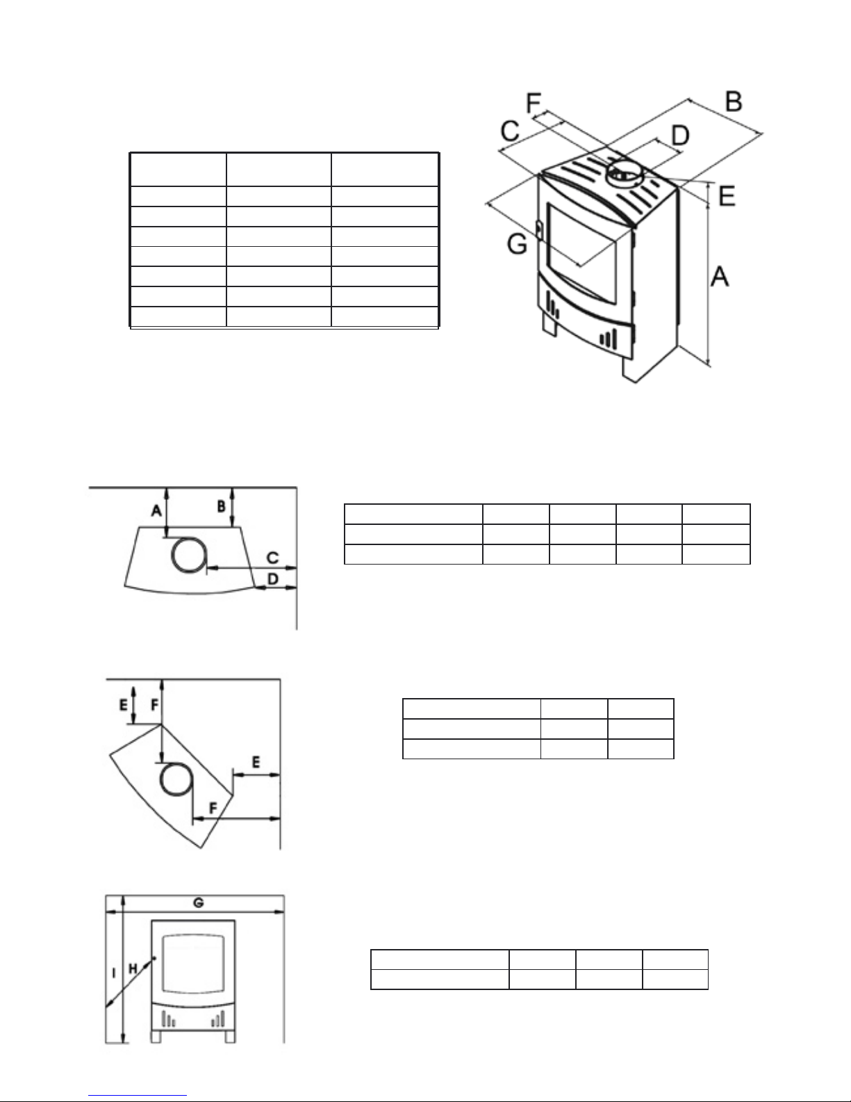
X33 R33
A 31¾” (807 mm) 31¾” (807 mm)
B 16¼” (390 mm) 16¼” (390 mm)
C 16” (404 mm) 15¾” (400 mm)
D 6” (150 mm) 6” (150mm)
E 37” (942 mm) 37” (942 mm)
F 5¼” (132 mm) 5” (113mm)
G 21” (542 mm) 21” (542 mm)
X33 and R33 steel body models
Dimensions
Clearances to Combustible Materials
Back and side wall clearances
Corner clearances
Connector pipe A B C D
Single wall 11” 10” 24” 18½”
Double wall 8” 7” 23” 17½”
Alcove clearances
Minimum ceiling height: 30” (unit to ceiling)
Connector pipe E F
Single wall 10” 15½”
Double wall 9½” 15”
Minimum ceiling height: 30” (unit to ceiling)
Connector pipe G H I
Double wall 48” 28” 60”
The following clearances may only be reduced by means approved by the regulatory authority.
5
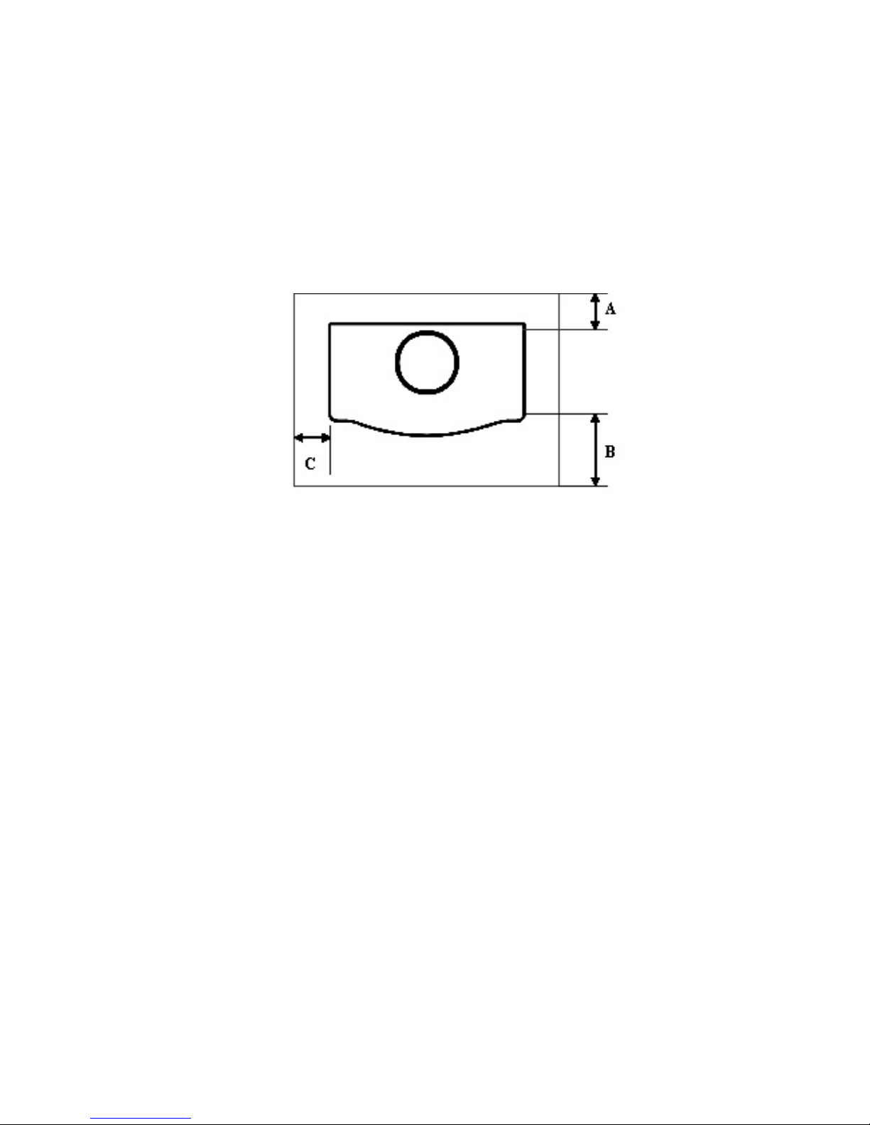
Floor Protection Requirements
A non-combustible floor protector (hearth extension) must be installed under the unit.
Check with local building authorities as to what other materials are acceptable.
The floor protector must extend:
1. Beyond the front door, a minimum of 16 inches (400 mm) in USA and 18 inches (450 mm) in Canada. See
measurement “B” on the floor protection drawing below.
2. On both sides of the unit, a minimum of 5 inches (125 mm) in USA and 8 inches (200 mm) in Canada. See
measurement “C” below.
3. On the back of the unit, a minimum of 0” (0 mm) in USA and 8 inches (200 mm) in Canada. See
measurement “A” below.
Notice: In case of installation with horizontal pipe, the floor protection must be extended beyond the back of the
appliance under the chimney connector and 2” (50 mm) beyond each side of the chimney connector.
Minimum requirements for floor protection on combustible floors
Types of Chimneys
The Chimney is a vital part of your stove installation. Your stove must be connected to either a code-approved
masonry chimney (a flue liner may be required), or a 6-inch diameter factory built chimney complying with the UL
requirements for Type HT chimneys (regulation UL 103 and ULC S629).
All chimneys must be installed either according to the local building codes in the case of a masonry chimney or
according to the chimney manufacturer’s instructions in the case of a factory-built metal chimney. See the chimney
manufacturers instructions for exact specifications. An oversized chimney may result in less than optimum
performance. Installations into a large, masonry chimney may require a liner to improve performance.
Chimney Inspection
Existing chimneys must be inspected before installing your stove. Consult your local building department for chimney
code requirements. A masonry chimney should have a code-approved liner. This liner must not have broken or
missing pieces. Some non-code masonry chimneys may be brought up to code by being relined. (Consult your dealer
or qualified chimney sweep.) Factory built metal chimneys should also be inspected, first for creosote deposits (which
would be removed), and then for integrity of the stainless steel liner. Look for obvious bulges in the lining, which may
indicate the need to replace that section (use a bright flashlight). Also inspect the attic to see that the chimney has
proper clearance to combustible framing members.
6

Draft Requirements
The appliance is merely one component of larger system. The other equally important component
is the venting system. This is necessary for achieving the required flow of combustion air to the
fire chamber and for safely removing unwanted combustion by-products from the appliance. If the
venting system’s design does not promote these ends, the system may not function properly. Poorly
functioning venting systems may create performance problems, as well as be a safety hazard
(i.e. an oversized chimney may result in less than optimum performance. Installations into a large
masonry chimney may require a liner to improve performance).
THE RECOMMENDED DRAFT REQUIREMENTS FOR YOUR STOVE IS NO LESS THAN -.04
AND NO GREATER THAN -.08. OPERATION OF YOUR STOVE WITH A DRAFT GREATER
THAN -.08 CAN POSSIBLY CAUSE DAMAGE TO THE STOVE AND VOID THE WARRANTY.
SPECIAL NOTE: A barometric damper is recommended for installations of stoves in areas that
may have high winds, which can affect the draft. The installation must be only in units with a newly
constructed chimney, free of creosote deposits. The barometric damper is an automatic device
designed to regulate the draft in a heating appliance, which in turn, stabilizes the chimney temperatures,
lessening the potential of over-firing. Do not place the barometric damper greater than 24 inches (610 mm) above the
unit. Excessive draft will lead to poor control of the burn rate, possible over-firing of the stove and damage to the cast
iron components of the firebox. Most barometric dampers are calibrated in inches of water column and can be set to
draft requirements of -.03 to -.08 inches (-7.5 to -20 Pa). It is recommended that the barometric dampers to be set
between -.05 and -.06 inches.
Chimney Height requirements
According to the American National Standards Institute ANSI/NFPA 211-92, draft 1-7, a chimney or vent shall be so
designed and constructed to develop a flow sufficient to completely remove all flue and vent gases to the outside
atmosphere. The venting system shall satisfy the draft requirements of the connected appliance in accordance with
the manufactures instructions.
The “3-foot, 2-foot, 10-foot rule” on chimney height states that a chimney must be:
1. At least 3 feet higher than the highest part of the roof opening through which it passes,
2. and at least 2 feet higher than any part of the roof within 10 feet, measured horizontally.
Due to prevailing winds, local terrain, adjacent tall trees, a hill or ravine near the home, or adjacent structures,
additional chimney height or a special chimney cap may be required to assure optimum performance.
.02
.01
.03
.04
.05
.06
.07
.08
.09
.05
.1
.2
.3
.4
.5
.6
.7
.8
.9
1.0
IN.OF WATERDRAFTOR PRESSURE-LOW RANGE
IN.OF WATERDRAFTOR PRESSURE-HIGH RANGE
Draft gauge
7
Standard Installation Procedure
1. Position the unit no closer than the minimum clearances to combustible materials. Check that no overhead
cross members in the ceiling or roof will be cut. Reposition unit if necessary, being careful not to move closer
than the minimum clearances.
2. Mark the position of the required floor protector on the floor. Remove the unit and install the floor protector.
3. Position the unit on the floor protector at the proper clearances.
4. Install a 6-inch diameter, minimum 24 MSG black or 26 MSG blued steel connector pipe on the flue collar of
the unit.
5. The stove is NOT to be connected to any air distribution duct or system. A chimney connector shall not
pass through an attic or roof space, closet or similar concealed space, or a floor, or ceiling. Where passage
through a wall or partition of combustible construction is desired, the installation shall conform to CAN/CSA B365, Installation Code for Solid-Fuel-Burning Appliances and Equipment. (Canadian installations only).
6. Use a 6” chimney connector adapter to connect the chimney connector up to the chimney. The small ends of
the chimney connector should all point down to ensure a drip-free installation.
7. Check that all clearances are still within the allowable tolerances.
8. Secure adjoining sections of chimney connector to each other using three equally spaced sheet metal screws.
Secure the connector pipe to flue collar using three equally spaced sheet metal screws. DO NOT secure
chimney connector to chimney with screws.
9. The unit must be connected to either:
• a code-approved masonry chimney with a flue liner, or
• a 6 inch diameter factory built chimney complying with the requirements for Type HT chimneys in the
standard UL 103 and ULC S629.
WARNING:
DO NOT CONNECT THIS UNIT TO A CHIMNEY FLUE SERVING ANOTHER APPLIANCE.
UNIT MUST BE INSTALLED ACCORDING TO ALL LOCAL CODES. A BUILDING PERMIT MUST BE OBTAINED
BEFORE INSTALLING.
SAVE THESE INSTRUCTIONS FOR FUTURE REFERENCE.
DO NOT INSTALL IN A MOBILE HOME.
READ ALL INSTRUCTIONS CAREFULLY BEFORE STARTING THE INSTALLATION.
UNIT MUST BE PROPERLY INSTALLED OR LISTING WILL BE VOID.
INSTALLATIONS OTHER THAN THOSE SPECIFICALLY COVERED HEREIN HAVE NOT BEEN CONFIRMED BY
TEST AND ARE NOT COVERED BY THE LISTING.
Freestanding Installations
If the chimney connector must pass through a combustible wall to reach the chimney, follow the recommendations in
the Wall Pass-Through section that follows.
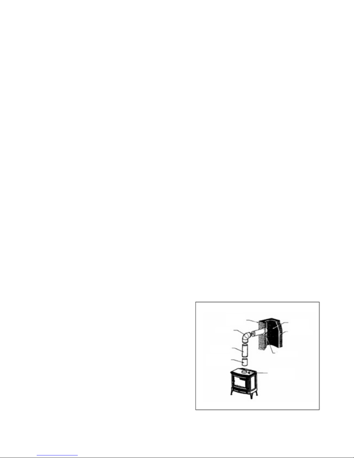
The opening through the chimney wall to the flue (the “breach”) must be lined with either a ceramic or metal cylinder,
called a “thimble”, which is securely cemented in place.
Fig. A: Chimney connection in a freestanding installation
8
Most chimney breeches incorporate thimbles, but the fit must
be snug and the joint between the thimble and the wall must be
cemented firmly (Fig. A)
A special piece called the “thimble sleeve”, slightly smaller in
diameter than standard connectors and most thimbles, will
facilitate the removal of the chimney connector system for
inspection and cleaning. Thimble sleeves are available from
your local dealer.
To install a thimble sleeve, slide it into the breech until it is flush
with the inner flue wall. Do not extend it into the actual flue
passage, as it could interfere with the draft.
The thimble sleeve should protrude 1-2” (25-50 mm) into the
room. User fire cement and thin gasketing to seal the sleeve
in place in the thimble. Secure the chimney connector to the
outer end of the sleeve with sheet metal screws.
Chimney
Elbow
Slip Pipe
Standard
Connector
Flue Liner
Flue Liner
Thimble
Flue Collar
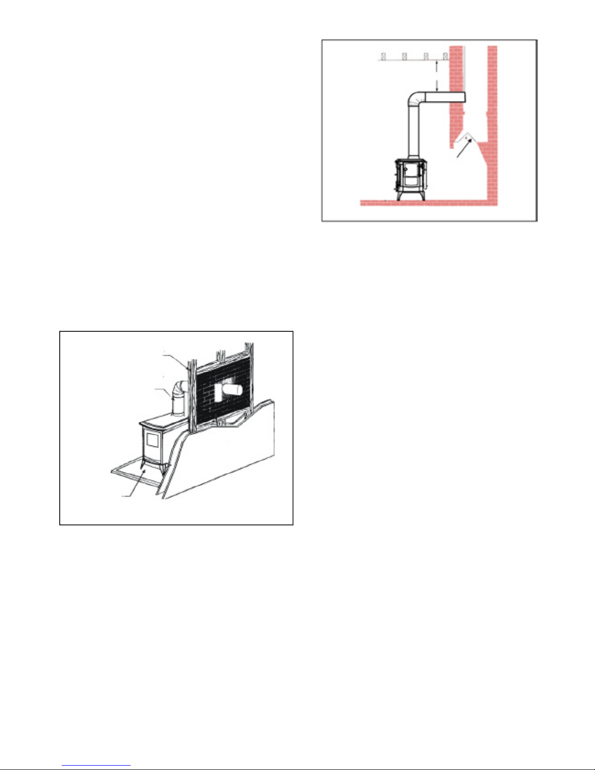
Above a Fireplace
In this type of installation, the chimney connector rises
from the stove, turns 90°, and then goes into the fireplace
chimney (Fig. B) The liner of the fireplace chimney should
extend at least to the point at which the chimney connector
enters the chimney. Follow all the guidelines for installing
a chimney connector into a freestanding masonry chimney,
and pay special attention to these additional points:
• Double check the connector clearance from the
ceiling: 18” minimum.
• The fireplace damper must be closed and sealed
to prevent room air from being drawn up the flue,
thereby reducing the draft. However, it must
be possible to re-open the damper in order to
inspect the chimney.
Fig. B: Chimney connector enters the chimney above a fireplace
Wall Pass-Through
Whenever possible, design your installation so that the wall connector does not pass through a combustible wall. If
you are considering a wall pass-through in your installation, check with your building inspector before you begin. Also
check with the chimney connector manufacturer for any specific requirements. Accessories are available for use as
wall pass-throughs. If using one of these, make sure it has been tested and listed for use as a wall pass-through.
Fig. C: An example of an approved wall pass-through
9
Chimney connector enters chimney above the
Wall Stud
The National Fire Protection Association (NFPA) has
established guidelines for passing chimney connectors
through combustible walls. Many building code
inspectors follow these guidelines when approving
installations.
The methods approved by the NFPA are:
• Cutting away all combustible material in the
wall a sufficient distance from the single wall connector,
to provide the required 12” (300 mm) clearance for the
connector. Any material used to close the opening must
be non-combustible (as in Fig . C).
• Using a section of double-wall chimney with a
9” (230 mm) clearance to combustibles.
• Placing a chimney connector pipe inside
a ventilated thimble, which is then separated from
combustibles by 6” (150 mm) of fibreglass insulating
material.
• Placing a chimney connector pipe inside a section
of 9” (230 mm) diameter, solid-insulated factory built
chimney, with two inches of air space between the
chimney section and the combustibles.
Chimney Connector
Floor Protection
minimum 18”
seal the damper

Acceptable Types of Connector Pipe
Minimum Flue Diameter: Minimum 6”, Maximum 10”
Minimum recommended chimney height (from appliance to termination): 12’-15’
- When Using Single Wall Pipe: Install a 6-inch diameter, single wall, 24 MSG black steel or 26 MSG blued steel
connector pipe on the flue collar of the unit. The crimped ends of the pipeshould all point down. Additional sections of
single wall pipe should be fastened together with at least three sheet metal screws each section. All pipe connections
must be sealed (using high temperature silicone).
- When connecting to the factory-built ceiling support package, use the manufacturer’s transition piece, usually called
a dripless connector, to join single wall pipe to their factory-built chimney section.
- When using approved double wall pipe: Type L and listed doublewall connector pipe is acceptable. Install any
factory-built brand of pipe according to the manufacturer’s instructions. All pipe connections must be sealed.
- Chimney Connector Adapter - Use a 6-inch chimney connector adapter to connect the chimney connector up to the
chimney. The small ends of the chimney connector should all point down for a drip free installation. Secure adjoining
sections of chimney connector to each other using three sheet metal screws. Secure the connector pipe to flue collar
using three sheet metal screws. DO NOT secure chimney connector to chimney with screws.
- Connection to a factory built chimney - Your stove may be connected to a factory-built chimney conforming
to CAN / ULC – S629, Standard for 650°C Factory-Built Chimneys. All pipe connections must be sealed.
- For Reduced Residential Clearances Using Double Wall Pipe: Type L and listed double wall connector pipe is
acceptable. Install any factory-built brand of pipe according to the manufacturer’s instructions.
10
 Loading...