

Page 1

NL-RF2200 UHF RFID Reader
Hardware User's Manual
2014
www.nesslab.com
Page 2

Contents
1. Introduction
1.1 Overview
1.2 Composition
1.3 Reader Configuration
1.4 Reader Installation
1.5 Reader Physical Size
RFID Reader Hardware User Guide
1.6 Specification
1.7 RS-232 & GPIO Interface
2. Antenna
2.1 Scope
2.2 Composition and Materials.
2.3 Mechanical Dimensions.
2.4 Electrical specifications.
3. FCC Information to User
4. WARNING TO USER
5. Reader, Anrenna Troubleshoot Guide
2
Page 3

RFID Reader Hardware User Guide
1. INTRODUCTION
1.1 Overview
NL-RF2200 is a Fixed Type 900MHz RFID Reader, enables user to use RS232 or Ethernet Interface
for efficient and convenient use. It is suitable for various applications such as Logistic, Asset tracking,
Stock management, Parking lot management, Healthcare, Security, Transportation and bank system.
User can use up to 4 antennas per one reader, perfect for wide range reading application than
longer distance reading application.
◈ System configuration ◈
Network
Tag #1
PC
1.2 Composition
Reader main body
LAN
RS-232
Tag #2
Tag #N
Antenna
(Option)
DC5V/5A adapter LAN Cable
Antenna cable
(Option)
3
Instruction
Page 4

1.3 Reader Configuration
LED : Yellow – Ethernet cable connection indicator
Green – Recognition of Ethernet cable and Tag
Reading indicator
Red – Power indicator
DC5V : Using DC5V/3A adapter to supply power to RFID
reader.
RFID Reader Hardware User Guide
ANT1 / ANT2 / ANT3 / ANT4 :
Connecting antenna up to 4 using
cable.
RS-232 : To connect to PC or other device for data transmission or software upgrade.
LAN : To connect to PC or other device for data transmission or software upgrade.
4
Page 5

1.4 Reader Installation
◈ How to install or connect reader with antenna ◈
1. Make the reader stay still.
2. Connect each cable in the package.
◈ Connect adapter with power
supply code then connect adapter
jack to main body.
◈ In case of use of multi connect or
extension cable, avoid to exceed
voltage(rated current) over than
mentioned.
RFID Reader Hardware User Guide
◈ When connection Antenna cable
for each port, connect SMA Type
connecter to main body and N Type
connecter to Antenna.
◈ Connect LAN cable to main body
LAN port for Ethernet
communication.
◈ Connect RS-232 cable for serial communication
checking with right direction of the connecter.
◈ How to install antenna correctly ◈
1. Avoid metal material the front side of antenna in 2M due to cause of low performance.
2. Make the antenna stay still.
3. Antenna Cable per each ports should be not tangled and tied up.
5
Page 6
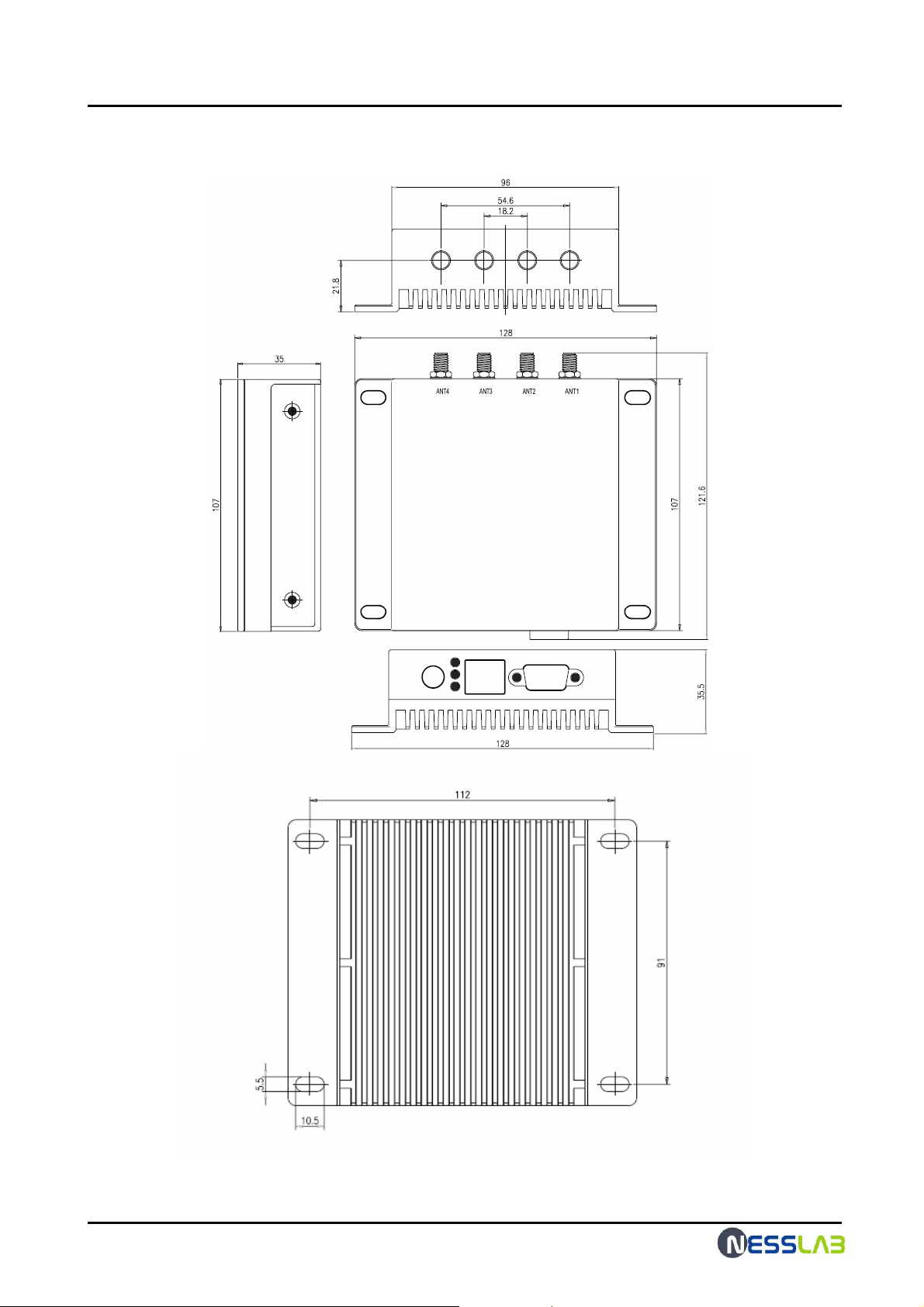
1.5 Reader Physical Size
☞ unit: mm
RFID Reader Hardware User Guide
6
Page 7
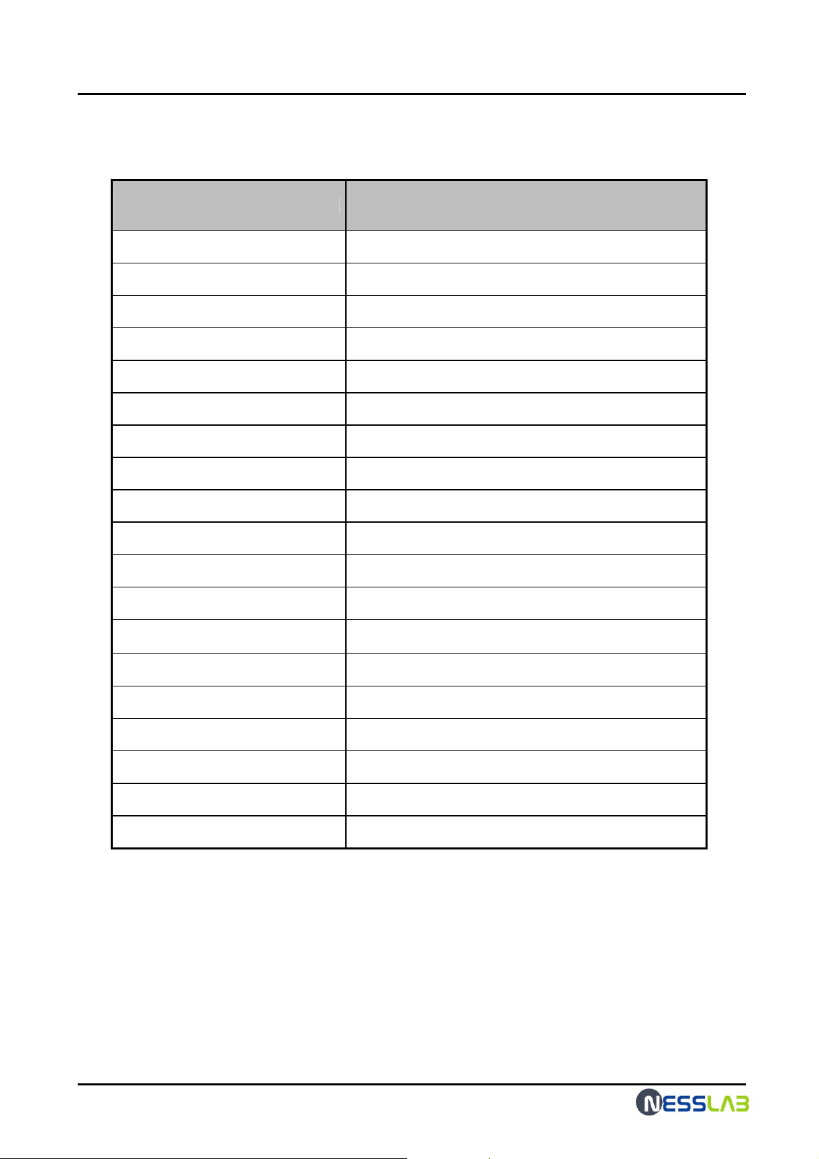
1.6 Specification
ITEM SPECIFICATION
RFID Reader Hardware User Guide
Model Number
Operating Frequency
RF Output Port
Hopping Channels
Channel Spacing
Channel Dwell Time
Modulation
RF Transmitter
Communication Interface
GPIO Support
Dimensions
Weight
Operating Temperature -10 ~ + 50 ℃
NL-RF2200
902.75 MHz ~ 927.25 MHz
4
50
500 KHz
< 0.4 seconds
Phase Reversal-Amplitude Shift Keying (PR-ASK)
< 1W (+30 dBm)
RS-232 (DB-9F), TCP/IP (RJ-45)
2-Input / 2-Output
107 x 98 x 32 mm
430g
LED Indicators
Input Power
Power Consumption
Protocols Support
Software Support
Compliance Certifications
Link, ACT, Power
DC 5.0V
12W
ISO 18000-6 Type C/ EPC Class1-Gen2
Reader Manager (API)
-
7
Page 8
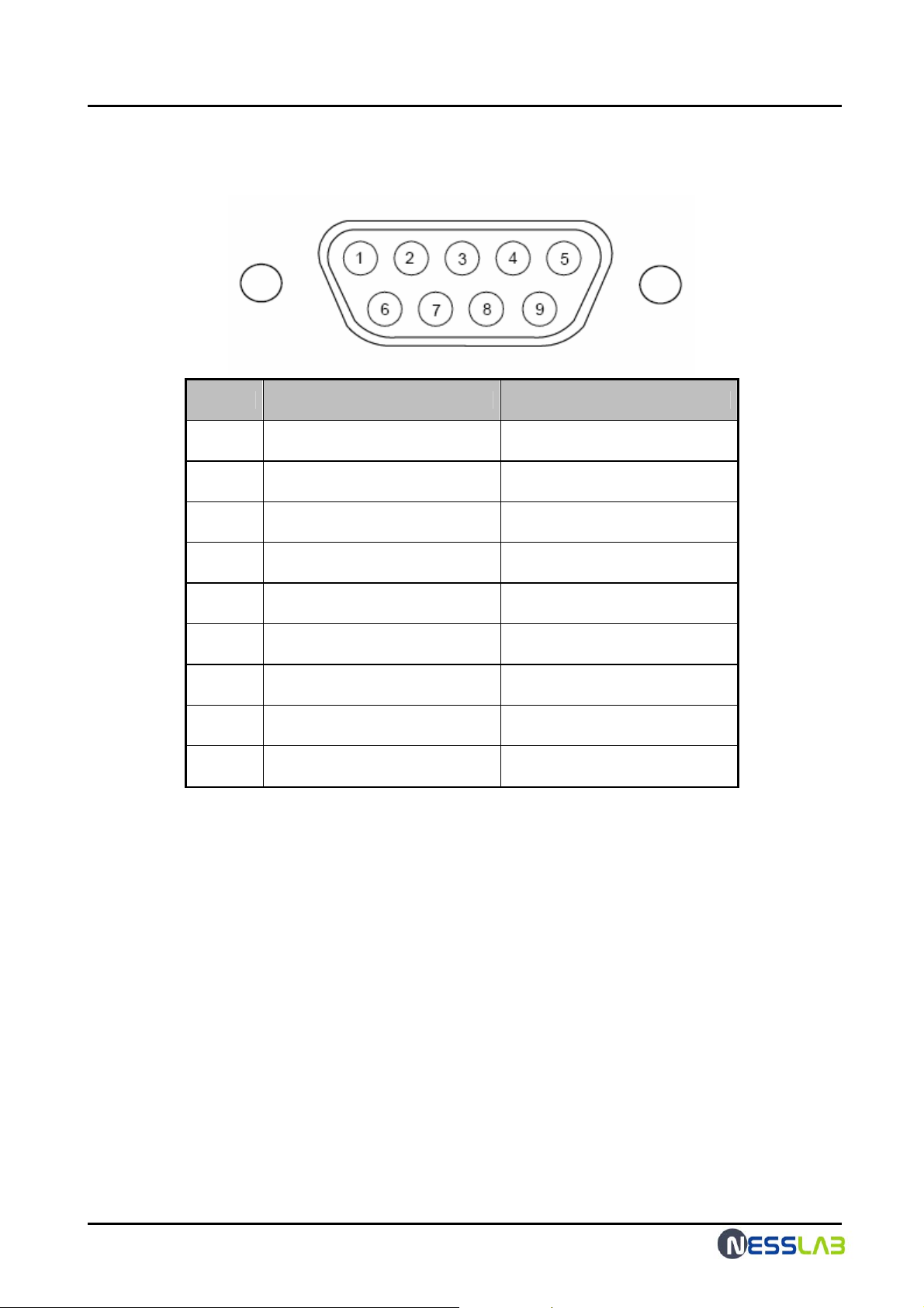
1.7 RS-232 & GPIO Interface
Pin NO. RS-232 Interface GPIO Interface (Option)
1
2
3
4
5
6
7
8
9
Not Connected +3.3V Output
Transmit Data Not Connected
Receive Data Not Connected
Not Connected I nput1
Ground Ground
Not Connected Output1
Not Connected Output2
Not Connected I nput2
Not Connected +5V or +12V Output
RFID Reader Hardware User Guide
8
Page 9
RFID Reader Hardware User Guide
2. Antenna
2.1 Scope
This specification covers the characteristics of the ceramic patch antenna element
for the ISM band
2.2 Composition and Materials.
1. Substrate : Air & Insulator
2. Electrode Plating : Copper & Aluninum
3. Terminal pin : Heat-resisting ABS
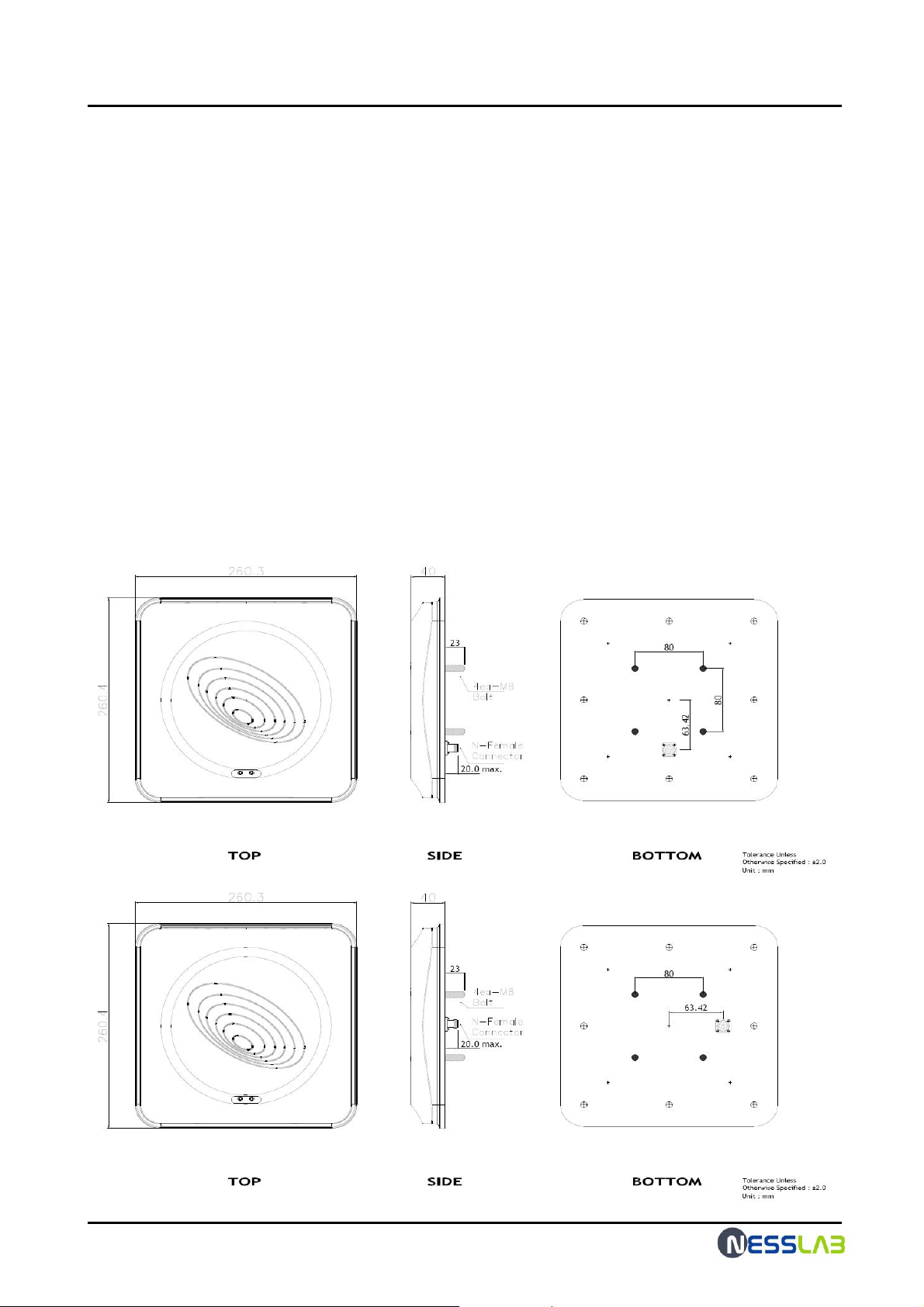
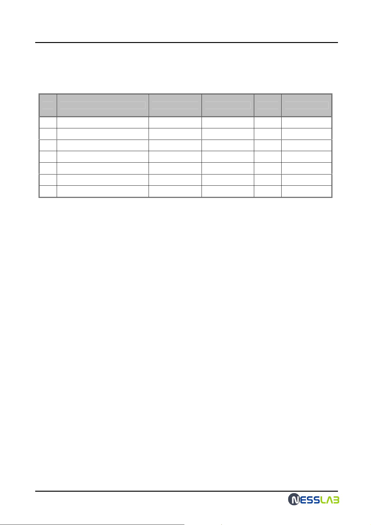
2.3 Mechanical Dimensions.
☞ unit: mm
9
Page 10
RFID Reader Hardware User Guide
2.4. Electrical specifications.
NO. Parameters Spec. Typical value Unit Remark
1 Center Frequency 919 MHz
2 Band Widt h @ - 10 dB R.L. 60 min. 80 MHz
3 VSWR 2.0 : 1 max. 1.1 : 1 Ratio @919 MHz
4 Gain @ Zenith 5.0 min. 5.0~6.0 dBiL @919 MHz
5 Axial Ratio 3.0 1.5~2.0 dB @919 MHz
6 Impedance 50 Ohms
7 Polarization RHCP
10
Page 11

RFID Reader Hardware User Guide
3. FCC Information to User
This equipment has been tested and found to comply with the limits for a Class A
digital device, pursuant to part 15 of the FCC Rules.
These limits are designed to provide reasonable protection against harmful
interference when the equipment is operated in a commercial environment.
This equipment generates, uses, and can radiate radio frequency energy and, if not
installed and used in accordance with the instruction manual, may cause harmful
interference to radio communications. Operation of this equipment in a residential
area is likely to cause harmful interference in which case the user will be required to
correct the interference at his own expense.
This device complies with Part 15 of FCC Rules.
Operation is subject to the following two conditions:
(1) the device may not cause interference, and
(2) the device must accept any interference, including interference that may cause
undesired operation of this device.
4. WARNING TO USER
- Change or modifications not expressly approved the manufacturer can void the
user's authority to operate this equipment.
- This equipment must not be co-located or operated in conjunction with any other
antenna or transmitter.
This equipment complies with FCC radiation exposure limits set forth for uncontrolled
equipment and meets the FCC radio frequency (RF) Exposure Guidelines in
Supplement C to OET65. This equipment must be installed and operated with at least
20cm and more between the radiator and person’s body (exclu ding e xtre mitie s: hands,
wrists, feet and ankles).
11
Page 12
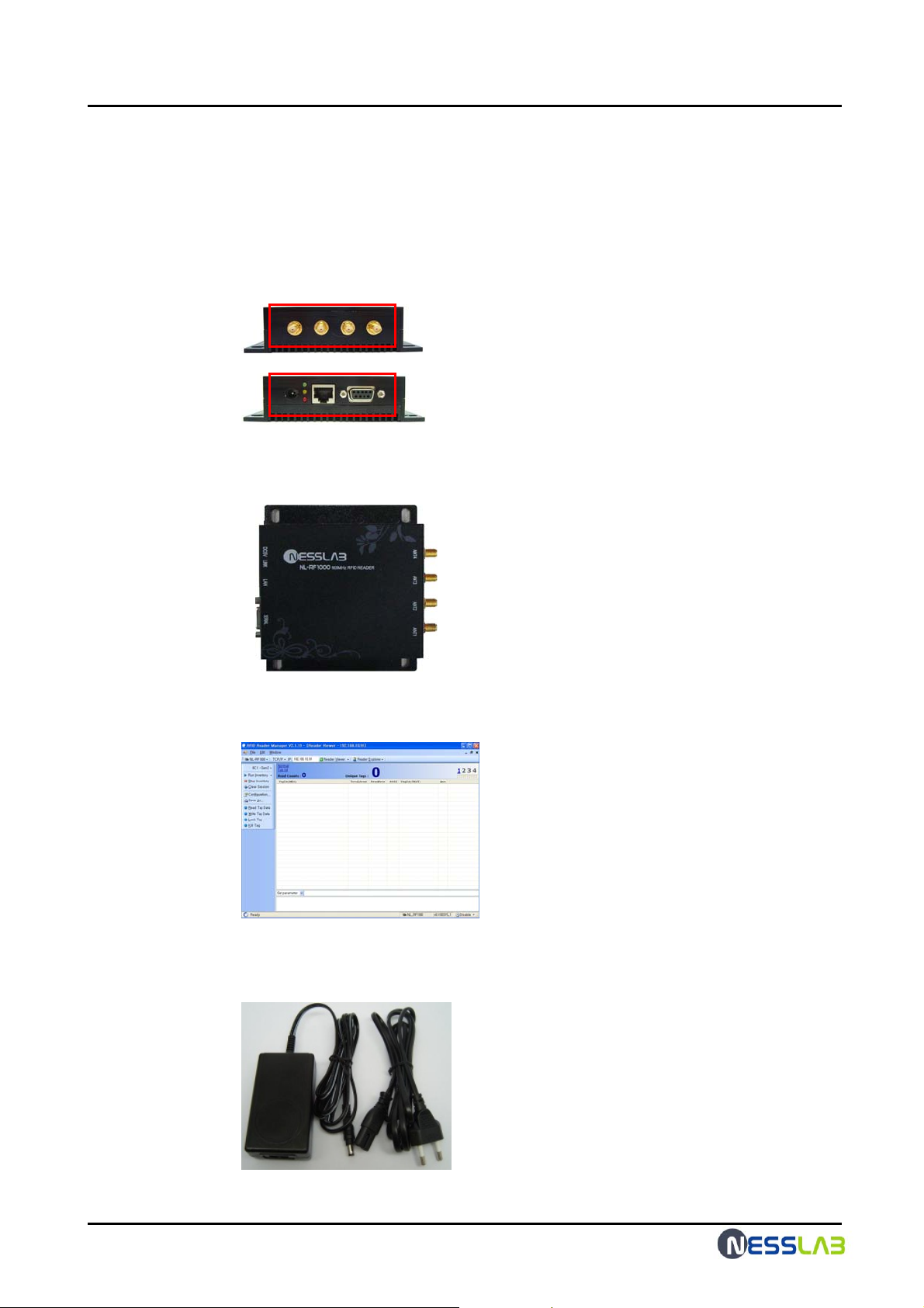
5.Reader, Anrenna Troubleshoot Guide
5.1 Fixed Reader and Antenna Troubleshoot
1. Confirm the demage of the out case and the inundation.
1) check the external connector .
2) check the inundation .(Check the clearance of the reader)
RFID Reader Hardware User Guide
2. Confirm the reader setup program.
1) The reader setup is the execution of the reader manager program
3. Confirm the error of the power.
1) Check the adaptor
(The output power is 5v dc)
12
Page 13
RFID Reader Hardware User Guide
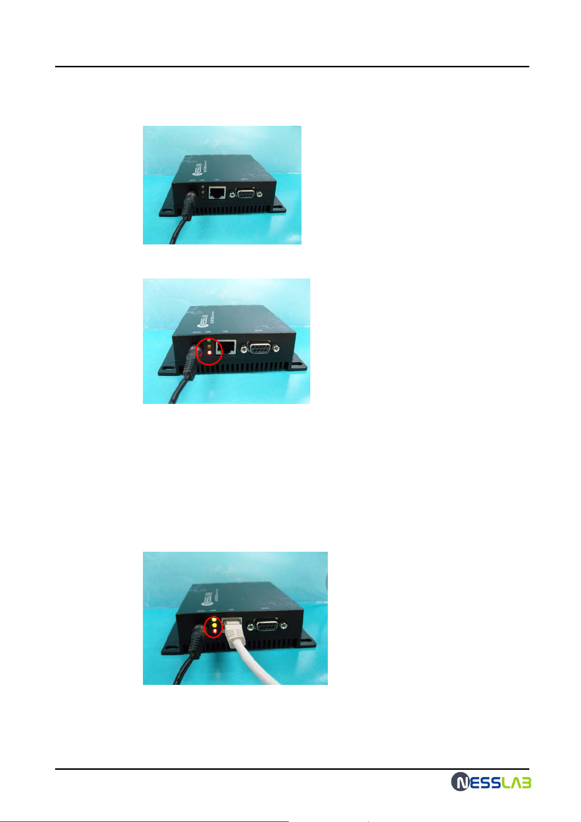
2) Check the connection of the ac adapter to the reader.
3) Confirm the red LED of the reader
4) If the red LED is off, the power is not supplied.
Check the connection of the ac power cord.
Change the output of the ac/dc adapter.
4. Confirm the LAN connection.
1) Confim the yellow LED.
13
Page 14
RFID Reader Hardware User Guide
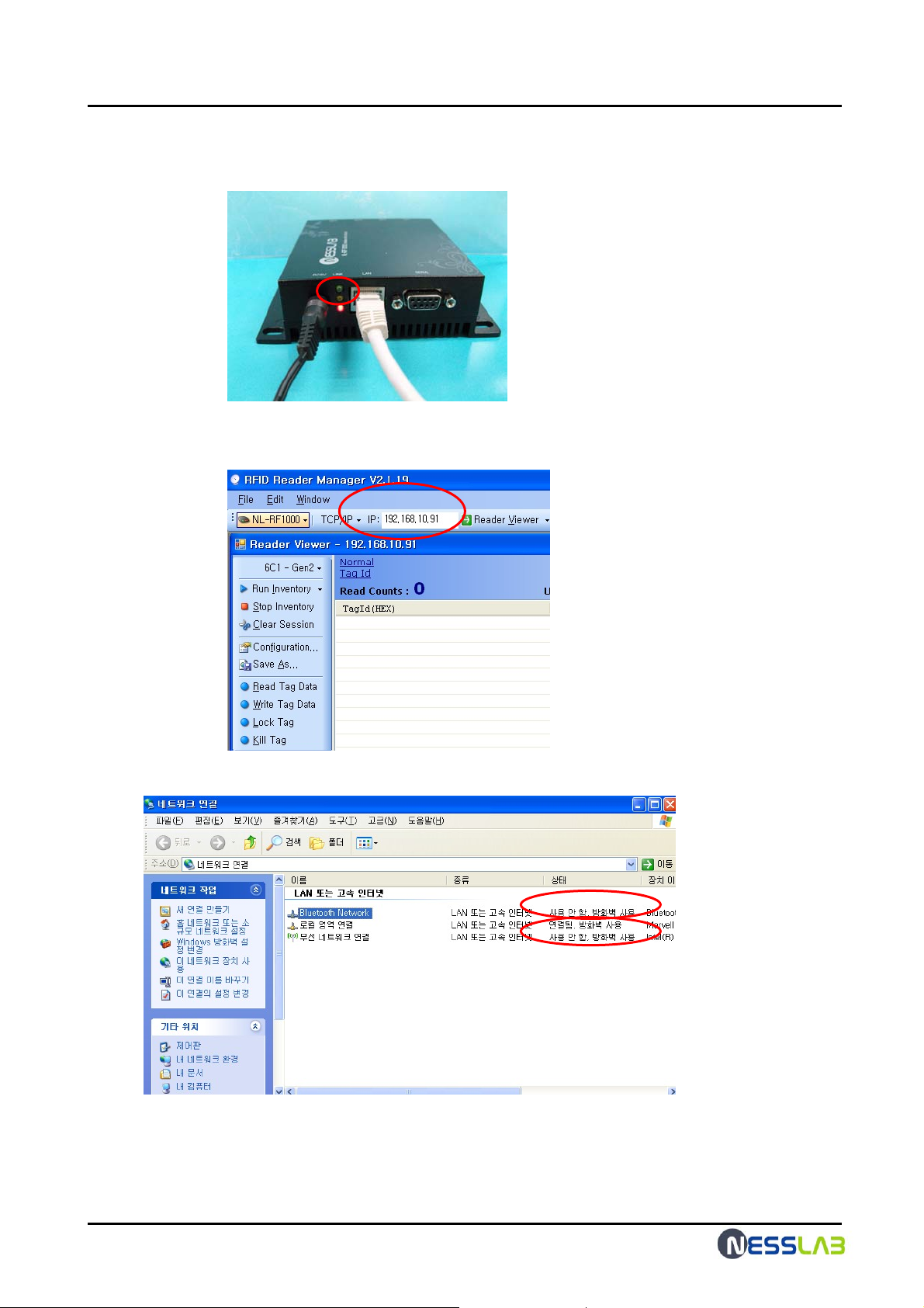
2) If the yellow LED is off , the ethernet is not connected to the host PC.
3) Confirm the reader IP (The default IP of the reader is 192.168.10.91)
4) Confirm the host PC setting ( disable the other connection )
14
Page 15
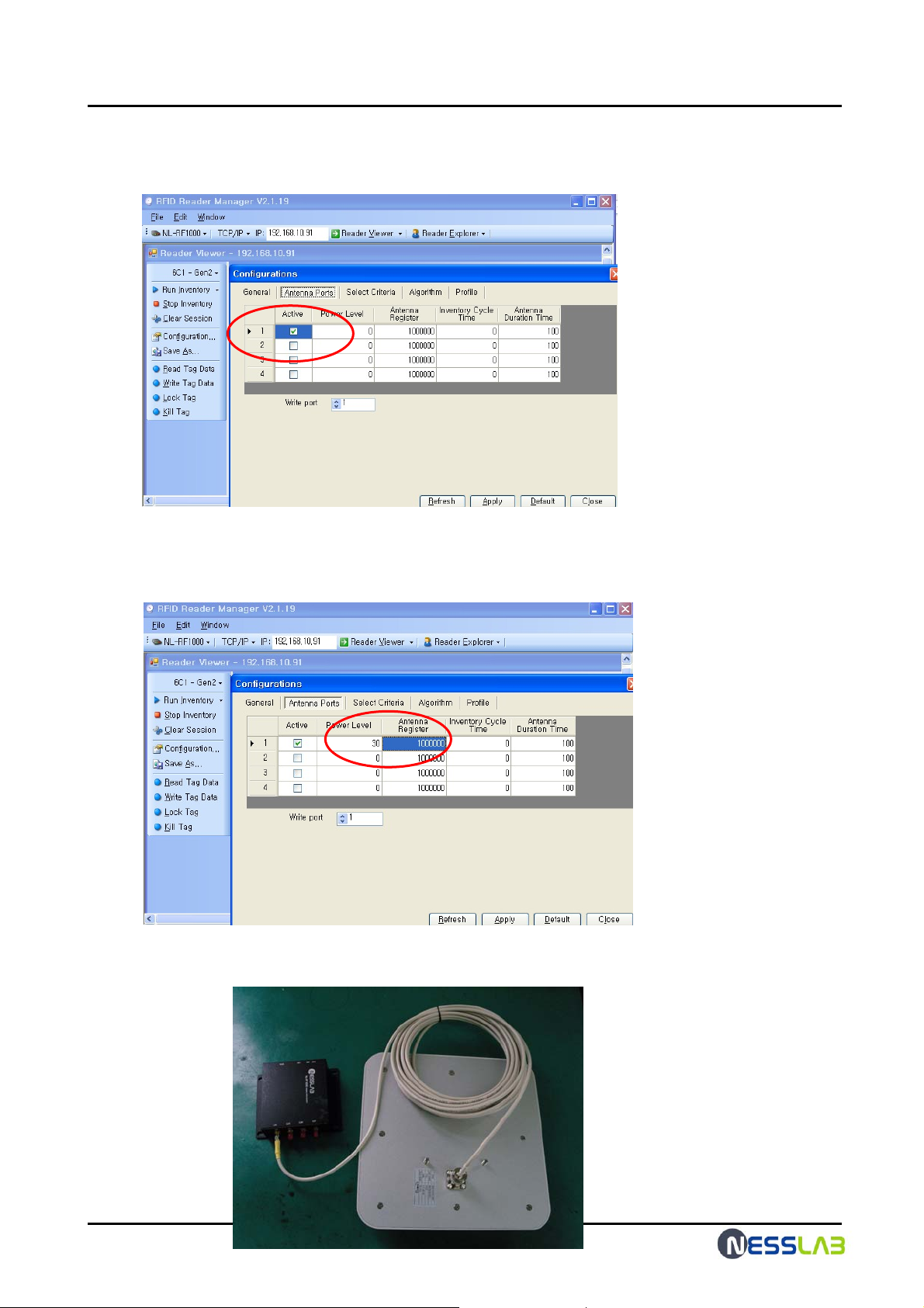
5. check the configuration of the reader.
1) check the antenna port at the reader manager configuration.
2) check the antenna power level and the antenna register.
The antenna power level is 15dBm ~ 30dBm.
The antenna register is 1000000
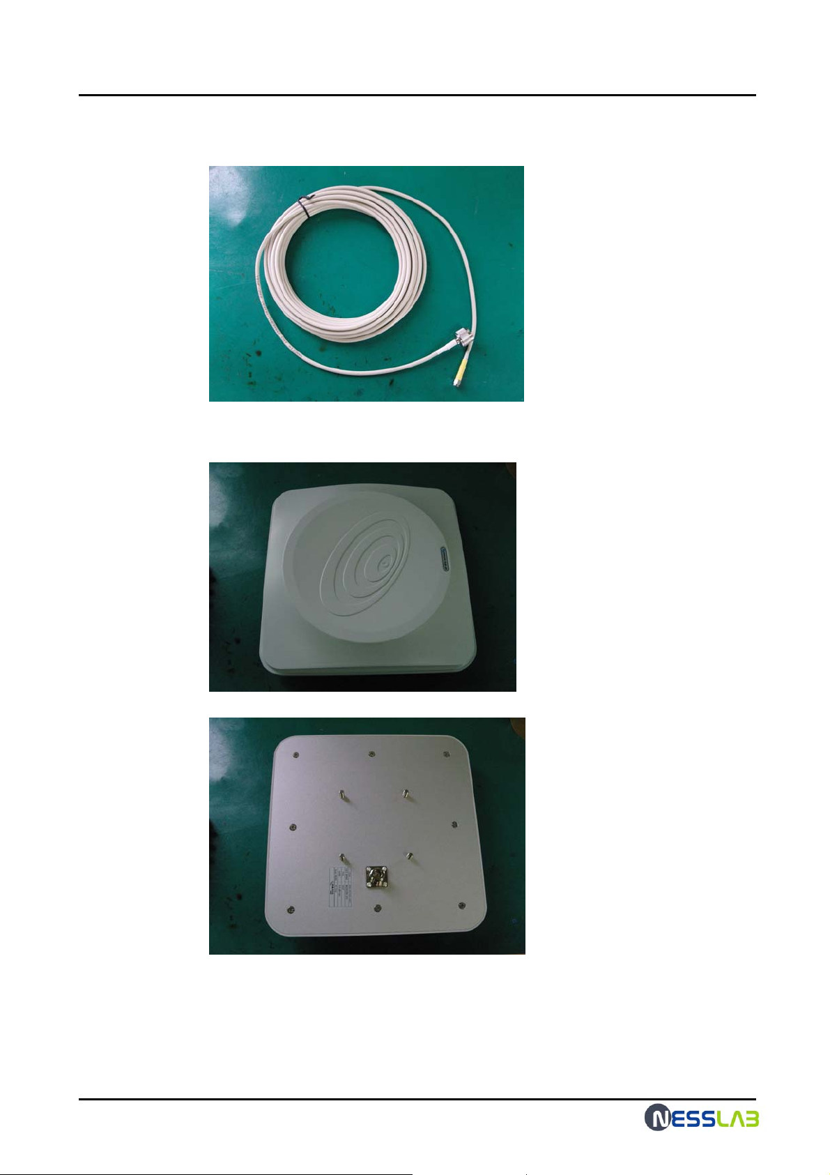
6. Check the antenna connection and the antenna opetration.
1) Check the antenna setting
RFID Reader Hardware User Guide
15
Page 16
RFID Reader Hardware User Guide
2) Check the antenna cable damages
3) Check the antenna damages.
7. Then ask the A/S center(+82-31-206-17 74), if the reader is out of order after all
that
16
 Loading...