

Page 1
[Original: 2017.03] (Version 1.0)
Reproduced with Permission
Copyright © 2017 Dongah Elecomm, Ltd
All rights reserved
Maintenance & Operation Manual
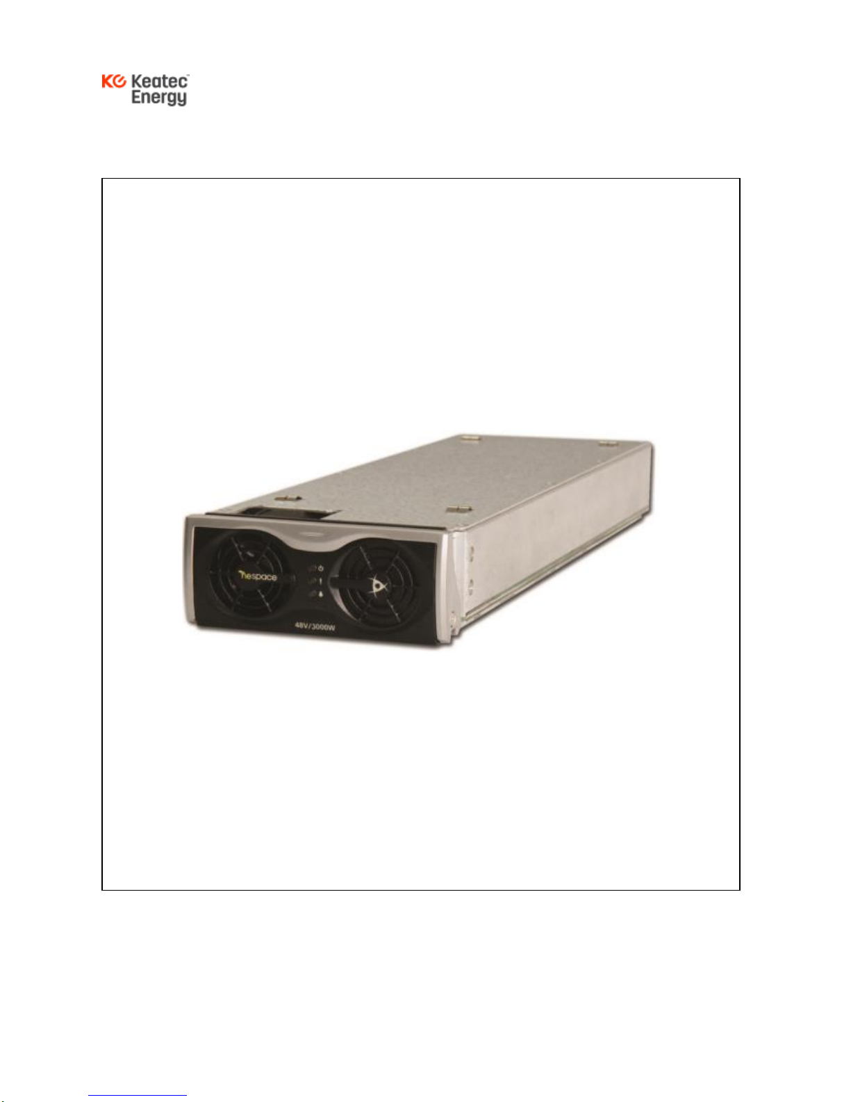
NESPACE 48/3K Rectifier Module
220V (1Phase 3Wire) AC Input
-54VDC @ 55.56A DC Output
3KW Rectifier Module
Page 2

NESPACE48/3K Operation Manual
Issue 1.0 March-2017
KE NESPACE KA Rectifier Control Unit Operation Manual English R 2016_07 V1_1
2 /21
- CONTENTS -
1 - RECTIFIER MODULE SPECIFICATIONS .......................................................................................................... 8
1.1 ELECTRICAL CHARACTERISTICS .......................................................................................................................... 8
1.1.1 Input Characteristics ................................................................................................................................ 8
1.1.2 Output Characteristics ............................................................................................................................. 8
1.2 EMISSIONS ........................................................................................................................................................... 8
1.2.1 Electro Magnetic Interference (EMI) ...................................................................................................... 8
1.2.2 Input Surge Voltage.................................................................................................................................. 9
1.2.3 Withstand Voltage .................................................................................................................................... 9
1.3 ENVIRONMENTAL CHARACTERISTICS .................................................................................................................. 9
1.3.1 Cooling ....................................................................................................................................................... 9
1.4 OPERATING HUMIDITY: 10% ~95%. NON-CONDENSING .................................................................................... 9
1.5 ACOUSTIC NOISE: ................................................................................................................................................ 9
1.6 PHYSICAL SPECIFICATIONS ................................................................................................................................. 9
1.6.1 Dimensions (W x D x H): ......................................................................................................................... 9
1.6.2 Weight: ....................................................................................................................................................... 9
1.7 SAFETY REPORTS: ............................................................................................................................................... 9
2 – NESPACE SHELF- TYPICAL INSTALLATION & CABLING....................................................................... 10
2.1 PREPARATION FOR RACK INSTALLATION .......................................................................................................... 10
2.2 CABLING TO A SHELF CONTAINING NESPACE48/3K MODULES ..................................................................... 10
2.2.1 AC Input Connection .............................................................................................................................. 10
2.2.2 DC Output Connection ........................................................................................................................... 11
2.2.3 Communication Cable Connection ...................................................................................................... 12
3 – SHELF INITIALIZATION & CHECK POINTS WITH NESPACE MODULES ............................................. 12
3.1 INSTALLATION CHECK LIST ................................................................................................................................ 13
3.2 RECTIFIER MODULE INSERTION & REMOVAL .................................................................................................... 13
3.2.1 Rectifier Module Installation .................................................................................................................. 13
3.2.2 Rectifier Module Removal ..................................................................................................................... 14
3.3 NORMAL OPERATION ......................................................................................................................................... 14
3.3.1 Initial Operation Status Check .............................................................................................................. 14
3.4 CORRECTIVE MEASURES ................................................................................................................................... 15
4 4 - NESPACE48/3K RECTIFIER MODULE CONFIGURATION ..................................................................... 15
4.1 ON LED (GREEN) ........................................................................................................................................... 15
Page 3

NESPACE48/3K Operation Manual
Issue 1.0 March-2017
KE NESPACE KA Rectifier Control Unit Operation Manual English R 2016_07 V1_1
3 /21
4.2 FAIL LED (RED) ............................................................................................................................................... 16
4.3 NESPACE48/3K RECTIFIER MODULE CONNECTOR PINOUT ......................................................................... 16
4.4 RECTIFIER SYSTEM OPERATION ....................................................................................................................... 17
4.5 RECTIFIER REMOVAL / REPLACEMENT .............................................................................................................. 17
4.6 RECTIFIER MODULE RESTART ........................................................................................................................... 17
5 - RECTIFIER MAINTENANCE .............................................................................................................................. 18
5.1 OVERVIEW .......................................................................................................................................................... 18
5.2 PERIODIC INSPECTION ....................................................................................................................................... 18
5.3 ADDING RECTIFIER MODULE ............................................................................................................................. 18
6 – PROBLEM SOLVING & FAULT FIXING .......................................................................................................... 19
6.1 PROBLEM SOLVING ............................................................................................................................................ 19
6.2 REPLACING PARTS WITHIN A SHELF.................................................................................................................. 19
6.3 ORDER OF REPLACEMENT ................................................................................................................................. 19
6.3.1 Replacement of Rectifier Module ......................................................................................................... 19
FIGURE
FIGURE 2-1. SHELF WITH NESPACE RECTIFIER MODULES INSTALLED...................................................... 10
FIGURE 2-2. AC INPUT & FG CABLE CONNECTION ............................................................................................. 11
FIGURE 3-1. NESPACE RECTIFIER UNIT FRONT VIEW ...................................................................................... 14
FIGURE 4-1. RECTIFIER MODULE CONNECTOR PIN ASSIGNMENT .............................................................. 16
TABLE
TABLE 2-1 OUTPUT CABLE & LUG ................................................................................................................ 11
TABLE 2-2 COMMUNICATION PIN TABLE ................................................................................................. 113
TABLE 3-1 CORRECTIVE ACTIONS PER ALARM ...................................................................................... 15
Page 4
NESPACE48/3K Operation Manual
Issue 1.0 March-2017
KE NESPACE KA Rectifier Control Unit Operation Manual English R 2016_07 V1_1
4 /21
SAFETY FIRST… at ALL TIMES !
- Before starting installation, operation, test. or repair work, carefully read and follow all directions
specified in this manual for safe operation of the system and to minimize risk to the operator.
- This product has been manufactured under strict quality management. If any potentially
hazardous procedure cannot be performed safely with regard to life or connected equipment,
contact Dongah Elecomm immediately.
- Pay special attention to sections throughout this manual that are highlighted with the following
WARNING or CAUTION symbols:
This WARNING symbol indicates a high risk that may cause death
or critical injury to the operator if proper procedures and safety
precautions are not used.
This CAUTION symbol indicates a serious risk that may cause injury
to the operator or damage to connected equipment if proper
procedures and safety precautions are not used. .
《Check of Contained Materials》
《Directions in Storage》
● Ensure that the product type and quantity received is the product
type and quantity that you ordered. Use the enclosed shipping
documents to verify all contents.
● Ensure that all parts and hardware are accounted for and with no
deformation, damage, peeling or scratched paints, or cable damage.
Page 5
NESPACE48/3K Operation Manual
Issue 1.0 March-2017
KE NESPACE KA Rectifier Control Unit Operation Manual English R 2016_07 V1_1
5 /21
● Secure and store this product package away from water, rain, direct
sunlight, and any potentially harmful gas or liquid.
● Store this product within the specified temperature (-40°C to +85°C)
and humidity (5% to 95%, non-condensing) conditions.
《Test & Repair》
Electric Shock, Fire
● Trained and qualified personnel should perform test and repair work
periodically with designated methods. (Violating this directive is a
risk to life and limb and may cause an electric shock or fire.)
● Only qualified labor with due knowledge and experience should
repair this product. (Violating this directive is a risk to life and limb
and may cause an electric shock or fire.)
● Whenever the AC input, DC output, and/or Battery voltage(s) are
applied or present, use precautions to avoid electric shock or short
circuit when the system is tested or repaired.
● Even when the system is turned on while commercial power has
failed, AC input may be fed to the system. Take particular attention
of the live AC input voltages present during test and repair work.
《Disposal》
● This product should be disposed under the ordinary industrial
wastes disposition procedure. Be aware that there may be industrial
waste management policies that need to be followed at the local,
state, and national levels.
《Directions in Operation》
Injury, Electric Shock, Fire
● Do not run this system in a place with flammable or corrosive gases,
dew or humidity. (It may cause an electric shock or fire.)
● Do not try to modify this product. (It may cause an electric shock,
burn, or fire.)
Page 6
NESPACE48/3K Operation Manual
Issue 1.0 March-2017
KE NESPACE KA Rectifier Control Unit Operation Manual English R 2016_07 V1_1
6 /21
● Operate this system under the environmental conditions specified in
this manual.
Take particular attention to voltage, frequency, temperature, humidity
and vibrations. (Violating the environmental requirements may cause
an electric shock or fire.)
● Before connecting the battery connections, load and gruonding wires,
pay attention not to reverse the polarity of them. (Polarity reversal
may cause fire.)
● While the system is connected, do not touch any battery wire, load or
grounding wire ports. It may cause an electric shock or death.
● Pay attention not to reverse the polarity of signaling cables and
detection cables when connected. (It may cause a fire.)
● Do not leave excess or foreign materials (such as sheathes of
electric wires or hardware) on top of or inside the product. It may
cause an electric shock or fire.
● The DC outputs are connected to the battery before the system starts
to be driven. Pay close attention not to cause an electric shock or
short circuit.
● When the rectifier units are inserted into the shelf, be aware that the
live AC input voltage is fed to the Connector in the rack side. (It may
cause an electric shock.)
● When you insert or remove a rectifier unit from or into the shelf, be
aware of the unit mey be hot enough to cause a burn injury.
● Do not insert an object or finger into the ractifier unit fan. (It may
cause an injury.)
● When handling rectifier units, pay close attention not to touch any
open connector pins. (It may cause an electric shock.)
● When cables are connected, battery should be separated from the
rectifier system except one point of the conductor at each cell.
● Start operation after all connections (battery, load, and grounding
wires/cables) are made but Circuit Breakers are OFF.
● Connect the battery wire, load and grounding wire while the load side
has been unloaded and Circuit Breakers are OFF.
● External transmission signal should be ≤ 60V level and ≤ 0.5A.
● Rectifier unit should be inserted and removed using the guide rail of
the rectifier system, to engage connectors without damage.
Page 7
NESPACE48/3K Operation Manual
Issue 1.0 March-2017
KE NESPACE KA Rectifier Control Unit Operation Manual English R 2016_07 V1_1
7 /21
● ● Use caution during an AC failure event as the AC power may be
restored at any time. Use special care to lockout/tagout the AC
whenever necessary, check the presence of, and maintain the AC
input to the power shelf, as needed.
Page 8

NESPACE48/3K Operation Manual
Issue 1.0 March-2017
KE NESPACE KA Rectifier Control Unit Operation Manual English R 2016_07 V1_1
8 /21
1 - Rectifier Module Specifications
1.1 Electrical Characteristics
1.1.1 Input Characteristics
1) UL Rated input voltage : 1P3W AC: 99Vac ~ 264Vac
(Derates 18.68W/V below 176 Vac)
2) Max Input voltage operating range: 85Vac~ 285Vac
(Designed for nominal:176VAC ~ 285VAC)
3) Max Input current: 18.5A
4) Leakage current: 3.5A @ 264Vac
5) Input frequency: 47 ~ 63 Hz
6) Efficiency: typical 96% (at 40% ~ 60% load)
7) Power factor: ≥ 0.99 (at ≥ 50% load)
8) Protection: MAINS fuse on both Line 1 and Line 2; TVS for Transients
9) UVP: 77Vac (Auto-Recovery: 85Vac); OVP: 297Vac (Auto-Recovery: 285Vac)
1.1.2 Output Characteristics
1) Rated output voltage: -54.0V ±0.27V (at 50% load)
2) Operating voltage: -43.5V ~ -58.0V
3) Output current: 55.5A (at 240Vac Input)
4) Output connector: designed for backplane insertion
5) Line Regulation: ±0.5% (±0.27V) across full input range
6) Load Regulation: ±0.5% (±0.27V) across full load range
7) Over-Current Limit: power-limited to 3KW down to 48Vout; (limited to 62.5A
Between 48V~38Vout, then folds back (see datasheet Output Power curve)
8) Over- Volltage Protection: -58.5V~-59.5V (Recycle AC input to reset)
9) Output Ripple & Noise: ≤ 300mVp-p (max); ≤ 20mVrms (20MHz BW)
1.2 Emissions
1.2.1 Electro Magnetic Interference (EMI)
CE Mark, including:
✓ EN 55022:2010 +AC:2011 (Class A)
✓ /EN61204-3:2000
Page 9

NESPACE48/3K Operation Manual
Issue 1.0 March-2017
KE NESPACE KA Rectifier Control Unit Operation Manual English R 2016_07 V1_1
9 /21
1.2.2 Input Surge Voltage
✓ Voltage: 6kV (1.2 ×50 ㎲); Current: 3kA (8 × 20 ㎲)
1.2.3 Withstand Voltage
1) Input to Output: 3.0kVac (1 minute) or 4242Vdc (1 minute)
2) Input to Chassis: 1.5kVac (1 minute) or 2121Vdc (1 minute)
1.3 Environmental Characteristics
✓ Pollution Degree 2
✓ Altitude tested to < 2000 meters
✓ 3KW Max Power Range: -35°C ~ +45°C
✓ Full Power to -40°C (Cold Shutdown/Auto-recovery -35°C)
✓ Derated Power ro +75°C (Hot Shutdown/Auto-recovery +65°C)
1.3.1 Cooling
✓ Intelligent Fan control
✓ Front-to-back airflow
1.4 Operating Humidity: 10% ~95%. non-condensing
1.5 Acoustic Noise:
✓ < 60dBA (220Vac, full load, Ta > +40°C)
1.6 Physical Specifications
1.6.1 Dimensions (W x D x H):
✓ 108.2mm x 321.7mm x 41.0mm (4.26in. x 12.67in. x 1.61in.)
1.6.2 Weight:
✓ 2.30 kg (5.07 lbs)
1.7 Safety Reports:
✓ UL Report # E166582-A62-UL
✓ (UL-60950-1, 2nd Edition (UL Recognized)
✓ CAN/CSA C22.2 No. 60950-1-07, 2nd Edition
✓ EN60950-1:2006/A11:2009/A1:2010/A12:2011/A2:2013
✓ Tests conducted under CB Scheme, issued by UL International Demko A/S,
CB Certificate Number DK-56640-UL (Test Report Ref. No. C16O043A0C0 issue date 7-25-2016).
Page 10
NESPACE48/3K Operation Manual
Issue 1.0 March-2017
KE NESPACE KA Rectifier Control Unit Operation Manual English R 2016_07 V1_1
10 /21
2 – NESPACE Shelf- Typical Installation & Cabling
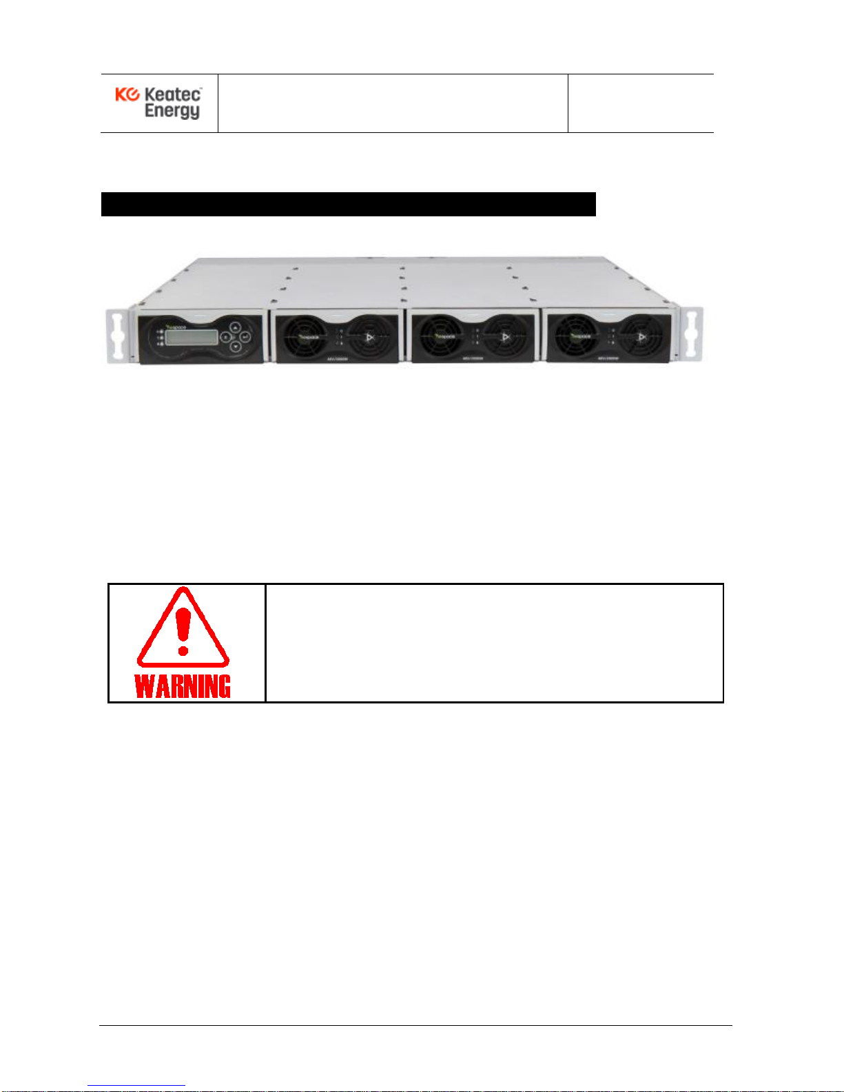
Example of NESPACE48/3K Rectifier Modules installed into a CSPS-6K Shelf
Figure 2-1. Shelf with NESPACE rectifier modules installed
2.1 Preparation for Rack Installation
The rectifier modules should be installed into a shelf using an indoor cabinet/rack in a clean, dry
location, with at least 50cm spacing front and rear of the shelf to allow for unrestricted air flow.
2.2 Cabling to a shelf containing NESPACE48/3K Modules
● Focus on and follow safety procedures while installing rectifiers.
● Before cable installation, use a DVM to verify AC and DC voltages
are not present. Use tagout/lockout, as needed.
● Before starting any operation, carefully read the following directions.
Inputs and outputs of the NESPACE rectifier is typically connected through a shelf backplane,
PCB traces, filter networks, bus bars, terminals, connectors, and cables.
Pay attention to AC input Line/Load/GND and DC output connection polarities.
2.2.1 AC Input Connection
The AC input includes a lightning surge arrestor (10kA) within the backplane in a typical shelf.
AC input cables to the Rectifier Shelf should be physically separated from DC output cables as
much as possible to minimize EMI.
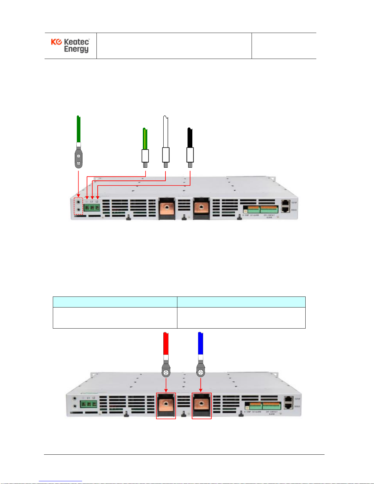
The AC 1ø3W input cable may be connected after AC voltage is verified to be OFF and
LOCKED-OUT. A typical 1U Rectifier Shelf configured with NESPACE48/3K rectifier modules is
shown in Figure 2.2, which shows the the Shelf’s rear-side power cable connections.
Page 11
NESPACE48/3K Operation Manual
Issue 1.0 March-2017
KE NESPACE KA Rectifier Control Unit Operation Manual English R 2016_07 V1_1
11 /21
* INPUT & FG cables should be as sized peoperly, at a minimum of:
AC Line (ACL) and AC Neutral (CAN) terminal: min. 6SQ (10AWG)
AC Ground (PE) : min. 8SQ (8AWG)
Frame Ground (FG) : min. 8SQ (8AWG) / 1 or 2 HOLE LUG (5Øx15mm)
Figure 2-2. AC Input & FG Cable Connection
2.2.2 DC Output Connection
DC output cables should be connected referring to Table 2-1 and Figure 2-3. Connect each
of the output cables to corresponding terminal.
Table 2-1 Output Cable & LUG
LOAD (-48V)
RTN (RETURN GROUND)
55A: 1HOLE LUG 25SQ or greater
110A: 1HOLE LUG 50SQ or greater
55A: 1HOLE LUG 25SQ or greater
110A: 1HOLE LUG 50SQ or greater
RTN
(M6)
-48V
(M6)
Figure 2-3 Output Cable Connection
AC Ground
(PE)
PE
ACL
ACN
Frame Ground
(FG)
ACL (L1)
ACN (L2)
Page 12
NESPACE48/3K Operation Manual
Issue 1.0 March-2017
KE NESPACE KA Rectifier Control Unit Operation Manual English R 2016_07 V1_1
12 /21
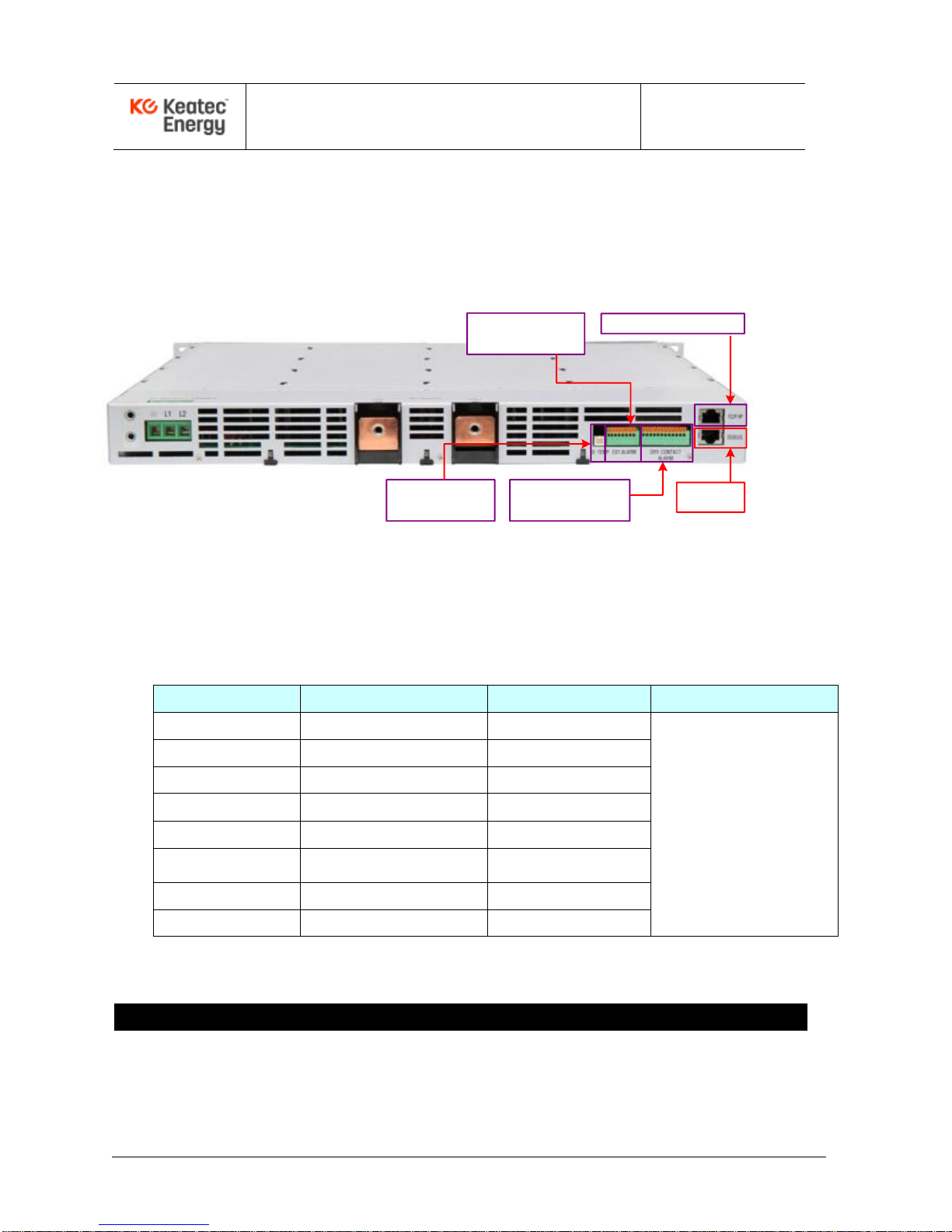
2.2.3 Communication Cable Connection
Rectifier alarm and operation status are sent out over Debug and Ethernet ports.
Pins are assigned as follows:
Figure 2-4. Communication Connection Ports
Table 2-2. Communication Pinout Table
> Ethernet (TCP/IP)
Pin NO
Name
Description
Comments
1
TX+
Transmit Data+
CONNECTOR: RJ45
2
TX-
Transmit Data-
3
RX+
Receive Data+
4
Not Used
5
Not Used
6
RX-
Receive Data-
7
Not Used
8 Not Used
3 – Shelf Initialization & Check Points with NESPACE modules
When installation procedures are finished, initialize the Rectifier Shelf and perform
the following functional test to check for any failures or alarms..
Ethernet (TCP/IP)
Debug
Digital Input
Alarm (4ports)
Dry contact
Alarm (6ports)
Battery Temp
Sensor
Page 13
NESPACE48/3K Operation Manual
Issue 1.0 March-2017
KE NESPACE KA Rectifier Control Unit Operation Manual English R 2016_07 V1_1
13 /21
1) Check that all circuit breakers and/or power switches have been turned off, and check
polarity and cable connection status using DVM.
2) Use a DVM tp ensure that the AC input power is correctly connected to the Shelf.
3) Check that the DC Output cables have been correctly connected, and check polarity.
4) Turn on the AC main Circuit Breaker.
5) Check that each installed NESPACE48/3K Rectifier Module front panel LED is green,
and verify that the DC output voltage is correct.
3.1 Installation Check List
To check installation of the Rectifier shelf, use the following procedure:
1) Check that the equipmment rack has been properly and firmly mounted to the floor.
2) Check that the dry contact alarms cable (optional) of the Control Unit is connected.
3) Ensure that the AC Input Circuit Breaker has been installed in the distribution
frame of the system.
4) Verify that the rack Frame Ground has been connected to the main ground busbar.
5) Check if the I/O cable has been correctly connected.
6) Verify that all installed NESPACE Rectifier Modules have been fully inserted.
3.2 Rectifier Module Insertion & Removal
3.2.1 Rectifier Module Installation
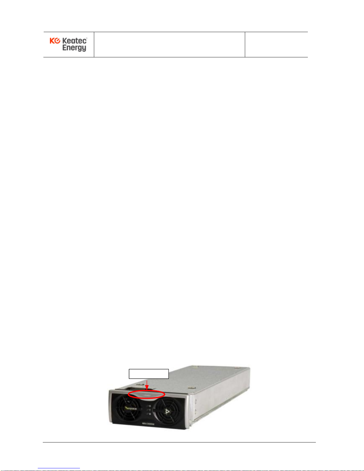
Each NESPACE48/3K Rectifier Module is hot-swappable so may be inserted with or
without the power applied to the shelf. The rectifier module should be inserted into the
shelf from the front. Insert each module until it reaches the mating connector then push
in the ejector to fully seat the connectors. The ejector will easily lock into place when
inserted and properly seated.
EJECTOR
Page 14

NESPACE48/3K Operation Manual
Issue 1.0 March-2017
KE NESPACE KA Rectifier Control Unit Operation Manual English R 2016_07 V1_1
14 /21
Figure 3-1. NESPACE Rectifier Unit Front View
3.2.2 Rectifier Module Removal
Remove the Rectifier Module by pushing in on the top front portion of the ejector
then pull the ejector handle to slide the module out from the shelf assembly.
3.3 Normal Operation
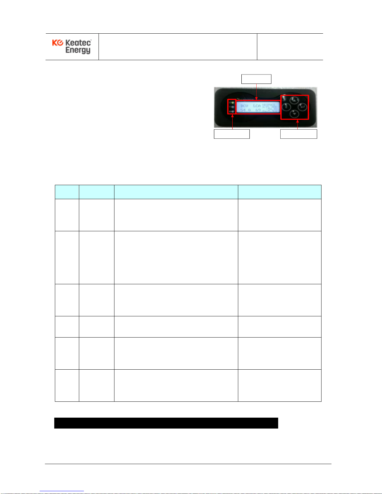
Status data is displayed on the LCD window of the Control unit. Use the push button
switches on the Control Unit front panel to edit or display setup values.
3.3.1 Initial Operation Status Check
1) Rectifier Module (NESPACE48/3K)
Check that the ON LED is illuminated.
Check that ALARM LED is turned off.
If the FAIL LED is ON, the Rectifier Module is not operating normally. In that case,
check the unit status on the LCD window of the Control unit.
Check that the Rectifier Module fan operates normally (pulls air in from front to
rear).
2) Controller (NESPACE-KA)
Check that the status indicator “FAIL” LED (red) is off.
Check that the audible alarm is not activated (it should remain quiet).
Check that alarms are not shown (as activated) on the LCD display and that the
LCD displays the present status correctly.
Note: For additional details, see the NESPACE-KA Rectifier Control Unit Operating Manual
Page 15
NESPACE48/3K Operation Manual
Issue 1.0 March-2017
KE NESPACE KA Rectifier Control Unit Operation Manual English R 2016_07 V1_1
15 /21
3.4 Corrective Measures
If the FAIL LED (red) is on while the
Rectifier Shelf is powered ON, the alarm
status will be displayed on the Control
Unit LCD window and the audible alarm
will sound. Check the alarm status and
take corrective measures, if needed.
LCD
WINDOW
LED
INDICATOR
SELECTION
BUTTON
Table 3-1 Corrective Actions per Alarm (optional, user defined)
No
ALARM*
CORRECTIVE MEASURES
Default (List)
Port1
AC input
AC High & Low voltage
Measure actual input voltage using the digital volt
meter. Verify input voltage UV, OV alarm settings.
AC UV : Under 174Vac
AC OV : Over 276Vac
Port2
Output
voltage
Verify default setting of output voltage.
Verify output voltage UV,OV alarm settings.
Verify individual current of unit and check if load
sharing is working correctly (only for the case of
Under voltage fail).
DC OV : Over 58Vdc
DC UV : Under 47.5Vdc
Port3
Rectifier
module
If an inserted NESPACE rectifier module inserted
has any problem, remove and reinsert it. If it fails
again, replace the NESPACE rectifier module.
UNIT FAIL
(Default.#1~#2, Max #3)
Port4
Environment
(Etc)
Check details using a PC and the Debug port to
check the actual status of the alarm.
Rack. High Temp (80℃)
Rack. Sensor fail (open)
Port5
Ext Alarm
Check details using a PC and the Debug port to
check the actual status of the alarm. Check the
Digital input (Ext) Alarm cable
Digital input Alarm fail
(Default: Normally open)
Port6
Control
If Control Unit has any problems, power the AC off
to the Shelf then remove and reinsert it. If it fails
again, replace the Control Unit.
* Alarm contact.type can be set arbitrarily to NO or NC(Normally Open or Normally Closed)
4 4 - NESPACE48/3K Rectifier Module Configuration
4.1 ON LED (GREEN)
The ON LED is lit (GREEN) when the Rectifier Module is in normal operation.
Page 16
NESPACE48/3K Operation Manual
Issue 1.0 March-2017
KE NESPACE KA Rectifier Control Unit Operation Manual English R 2016_07 V1_1
16 /21
If internal communication with the Control Unit fails, the ON LED slowly blinks.
4.2 FAIL LED (RED)
The FAIL LED is lit (RED) under one of the following conditions:
* When system is shut down due to the DC OV (OverVoltage) protection circuit.
* When system is shut down due to the OT (OverTemperature) protection circuit.
* When system is in a DC UV (UnderVoltage) due to an over-current limit condition.
* When the internal FAN has failed – FanFail (FF).
* When system shuts down due to the AC OV or AC UV exceeding rated spec limit.
* When output is not functioning or voltage falls below DC UV limit (for any reason).
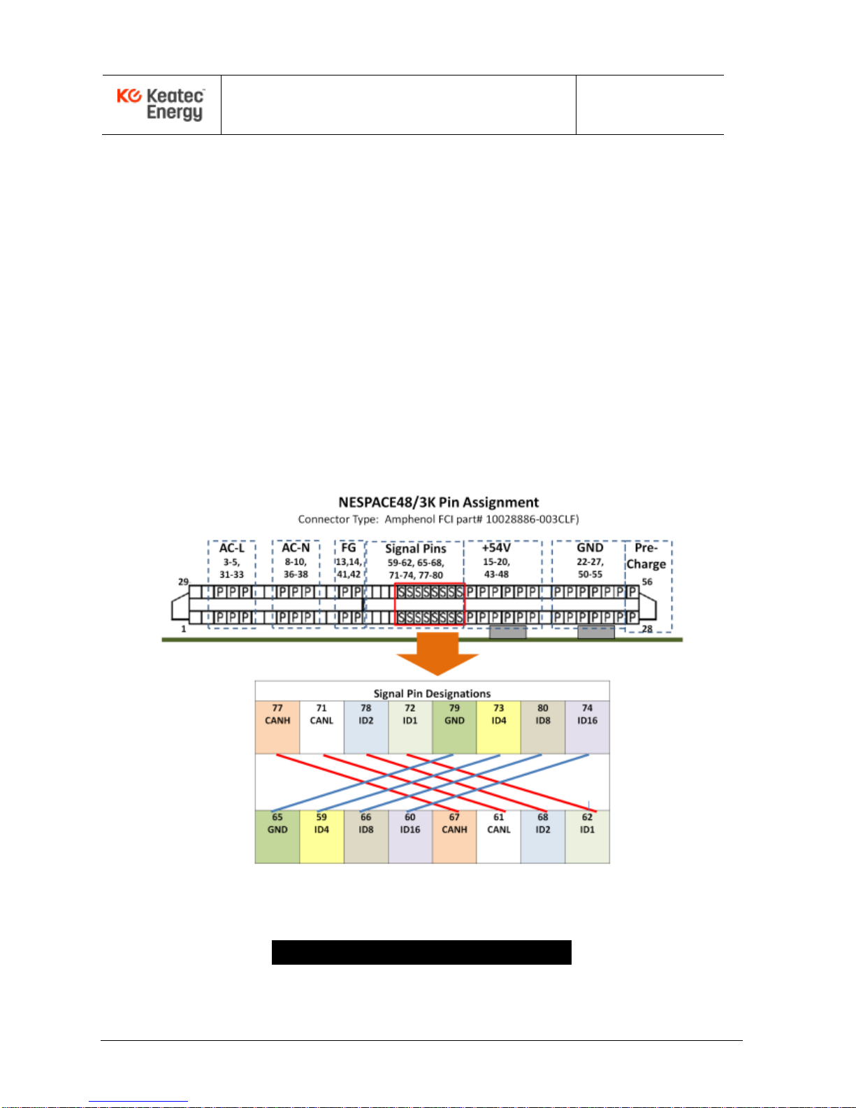
4.3 NESPACE48/3K Rectifier Module Connector Pinout
Figure 2-1. Rectifier Module Connector Pin Assignment
5 - Rectifier Module Operation
Page 17

NESPACE48/3K Operation Manual
Issue 1.0 March-2017
KE NESPACE KA Rectifier Control Unit Operation Manual English R 2016_07 V1_1
17 /21
4.4 Rectifier System Operation
① Check that each RM ON LED is illuminated (GREEN) for normal operation.
If the RM FAIL LED is on (RED), check module error status then remove
and reinsert the RM to check the status again.
② Verify that the RM ON LED is illuminated (GREEN) for normal operation.
If the FAIL LED is still on (RED), check the alarm displayed on the Control Unit LCD.
If any error on the rectifier system is not solved under the direction of above Table 3-1,
contact a Sales Representative or the headquarters of Dongah Elecomm.
4.5 Rectifier Removal / Replacement
① The Rectifier Modules are hot-swappable so can be replaced with AC power applied.
(Note that if any external battery has been connected, the Control Unit still operates.)
②
The Control Unit is not hot-swappable so replacement requires that the AC input
voltage be turned off and all external batteries be disconnected (BATT circuit
breakers OFF). Then the Control Unit can be replaced and the system power
restored.
4.6 Rectifier Module Restart
If a Rectifier Module output voltage is suspended due to a DC OverVoltage (OV),
manually turn off the main AC Circuit Breaker. Then, when the module is fully
discharged (LED off), turn on the AC Circuit Breaker to see if the event was isolated
or recurring. If the OV condition is not recovered, replace the Rectifier Module and
repeat this restart process to check that the replacement module clears the alarm.
Page 18

NESPACE48/3K Operation Manual
Issue 1.0 March-2017
KE NESPACE KA Rectifier Control Unit Operation Manual English R 2016_07 V1_1
18 /21
5 - Rectifier Maintenance
5.1 Overview
The purpose of this document is to provide guidelines to test the rectifier and setup
measures to restore the rectifier to normal operation within a shortest possible time
when any fault occurs to the system. Enough field-replaceable spare parts must be
maintained on-hand to prepare for replacement of units or components that may fail in
the field. Even though the fault location and reason are detected under the guidelines of
this Manual, if field repair work is not possible, or a long period of time is needed for
repair, the faulty units should be replaced with a spare one held in reserve. This allows
the system alarm to be cleared quickly and efficiently to minimize technician time and
maximize system up-time.
Note: As this rectifier is powered by AC voltage, it naturally may cause electric shock. If
external battery banks are also used, this battery voltage is fed to the system even
during an AC failure event. Because of the AC and/or DC presence, safety measures
should be taken during rectifier shelf repair and maintainance.
5.2 Periodic Inspection of Rectifier Shelf, Modules, and System
To guarantee effective operation of the system, periodic inspection is required.
Periodic inspection should be carried out once every 6 months.
1) Take care not to block the air ventilation holes with dust, dirt, or other debris.
2) Check the cable connections and tighten as necessary.
3) Check if internal temperature of the site is maintained at the rated levels.
4) Visually check all rectifier operation states and alarm states.
5) Check the equipment rack floor mount is maintained and ensure there is not any
water leakage at or near the installation site for the rectifier system.
5.3 Adding Rectifier Module
To expand the system capacity, rectifier modules are hot-swappable so may be inserted
into vacant slots while the Rectifier Shelf is powered up normally.
Page 19

NESPACE48/3K Operation Manual
Issue 1.0 March-2017
KE NESPACE KA Rectifier Control Unit Operation Manual English R 2016_07 V1_1
19 /21
1) Insert a rectifier module to the vacant slot until it reaches the mating connector then
push in the ejector to fully seat the connectors. The ejector will easily lock into place
when inserted and seated.
2) Confirm the Rectifier Module ON LED is illuminated GREEN.
3) On the Control Unit, check operation status of the newly inserted module for no
active alarms.
6 – Problem Solving & Fault Fixing
Repairing or troubleshooting Rectifier Shelves and Rectifier Modules should only
be performed by experienced workers observing all safety precautions.
* Jobs should be carried out in due order.
* Workers should not wear rings, watches or metallic accessories.
* If non-insulated conductors are used, always use a DVM toverify if any voltage is
present before attempting to perform any work in or around the Shelf or Rectifier.
- Circuits and boards should be protected from EMI.
6.1 Problem Solving
This rectifier has been designed for users to solve problems easily. The Control Unit LCD
window displays details of faults.
6.2 Replacing Parts within a Shelf
If a fault is suspected on a particular point, the field-replaceable unit (circuit board or
module) at that point should be replaced. Replacing individual components on a circuit
board or module should not be performed in the field.
6.3 Order of Replacement
6.3.1 Replacement of Rectifier Module
1) When a rectifier module is replaced, an alarm will be activated. Turn off the rectifier
module alarm from the control panel, or notify this fact to the person in charge.
2) To remove the faulty rectifier module, push in on the ejector on the Rectifier Module,
and then pull the ejector handle to remove the module from the shelf.
3) Slide in a new Rectifier Module along the mechanical guides until it reaches the
Page 20
NESPACE48/3K Operation Manual
Issue 1.0 March-2017
KE NESPACE KA Rectifier Control Unit Operation Manual English R 2016_07 V1_1
20 /21
backplane connector.
4) Carefully push in the ejector handle to lock the mating connectors. The ejector
handle should easily snap into place and lock into the Rectifier Module front panel.
5) Check that the module operates normally and that no alarms are activated.
Definitions
C/B : Circuit Breaker
S/W : SWitch
RMS : Root Mean Square
LVD : Low Voltage Disconnect
ACF : AC Fail(power failure)
ACV : AC Voltage
ALM : ALarM
AMP : AMPere
AUTO-FL MODE : AUTO-FLoating charging MODE
AUTO-EQ MODE : AUTO-EQualize charging MODE
DCV : DC Voltage
Comm. Fail : Communication Fail
Comp. : Compensation
Curr. : Current
DC : Direct Current
DCF : DC Fail
DCOV : DC Over Voltage
DCUV : DC Under Voltage
DCH : DisCHarge
FF : Fan Fail
LCD : Liquid Crystal Display
LED : Light Emitting Diode
LDA : output LoaD Ampere
MF : Module Fail
OV : Over Voltage
OCA : Over Current Ampare
OT : Over Temperature
REC : RECtifier
RX : Receipt channel
TX : Transmit channel
Temp : Temperature
UV : Under Voltage
V1.0 : Version 1.0
ERR : ERRor
ENT : ENTer
LCA : Load Current Ampere
Page 21

NESPACE48/3K Operation Manual
Issue 1.0 March-2017
KE NESPACE KA Rectifier Control Unit Operation Manual English R 2016_07 V1_1
21 /21
NESPACE48/3K RECTIFIER MODULE
MAINTENANCE & OPERATION
MANUAL
Copyright ©2017 Dongah Elecomm Corp.
All rights reserved
Information in this document is proprietary to Dongah Elecomm
No information contained here may be copied, translated,
transcribed or duplicated by any form without the prior written
consent of Dongah Elecomm.
Reproduced with Permission
 Loading...