

Page 1
Revision L, 29th Sep 2004
Nera Broadband Satellite AS
Page 2

Page 3

Nera SatLink Terminal
User Guide
Page 4
©
Copyright 2002-2004, Nera Broadband Satellite AS
All rights reserved. Reproduction, adaptation or translation without prior written
permission is prohibited, except as allowed under the copyright laws.
®
™
Notice
The names of products (hardware and/or software) mentioned herein are regarded to be
the property of their respective companies, regardless of whether or not registration is
indicated.
The information in this publication is subject to change without notice. Nera Broadband
Satellite AS makes no warranty of any kind with regard to this material, including, but
not limited to, the implied warranties or merchantability and fitness for particular
purposes. Moreover, Nera Broadband Satellite AS shall not be held liable for errors that
may occur herein or for incidental or consequential damage in connection with the
furnishing, performance or use of this material.
Publication no. 101557
Revision L, 29th Sep 2004
File: Nera SatLink Terminal User Guide Rev L
Nera Broadband Satellite AS
Bergerveien 12
PO Box 91
N-1375 Billingstad, Norway
Tel: +47 67244700, Fax: +47 66859115
E-mail: [email protected]
Website: http://www.nera.no/
Page 5

Nera SatLink Terminal User Guide
Table of Contents
1. INTRODUCTION........................................................................................................ 7
1.1 This User Guide.......................................................................................................... 8
1.2 Configuration overview...............................................................................................8
2. UNPACKING............................................................................................................ 10
3. INSTALLATION........................................................................................................ 10
3.1 Before installation..................................................................................................... 10
3.2 Front and back panels............................................................................................. 11
3.3 IDU Installation......................................................................................................... 13
3.4 ODU installation........................................................................................................ 14
3.5 Interface connections................................................................................................ 14
4. PC CONFIGURATION.............................................................................................. 16
4.1 Dynamic IP configuration of PCs connected to the Nera SatLink Terminal LAN ....... 16
4.2 Static IP configuration of PCs connected to the Nera SatLink Terminal LAN ............ 17
4.3 Tuning of TCP parameters........................................................................................ 18
5. USING THE COMMAND LINE INTERFACE OF THE SATLINK TERMINAL............ 20
5.1 Start-up sequence.................................................................................................... 20
5.2 CLI users access rights ............................................................................................ 21
5.3 Online help............................................................................................................... 21
5.4 Logging of events..................................................................................................... 22
5.5 CLI command summary............................................................................................ 23
6. NERA SATLINK TERMINAL CONFIGURATION...................................................... 25
6.1 Power on and logon.................................................................................................. 25
6.2 Initial configuration of parameters............................................................................. 26
6.3 ODU line-up.............................................................................................................. 33
6.4 Test of DVB-RCS connection ................................................................................... 36
6.5 Prepare the Nera SatLink Terminal for normal operation.......................................... 37
6.6 Backing up the current configuration......................................................................... 37
7. LAN DHCP SERVER............................................................................................... 38
8. QUALITY OF SERVICE............................................................................................ 40
8.1 Configuring QoS for the return link............................................................................ 41
9. RETURN LINK CAPACITY....................................................................................... 43
10. TRAFFIC INITIATED LOGON .................................................................................. 44
11. UPDATING THE NERA SATLINK TERMINAL SW................................................... 45
11.1 Automatic software update ....................................................................................... 45
11.2 Manual software update ........................................................................................... 46
11.3 Restoring the backup software ................................................................................. 47
12. SOFTWARE OPTIONS ............................................................................................ 48
12.1 Network Address Port Translation (NAPT)................................................................ 48
12.2 Generic Routing Encapsulation (GRE) and IP Tunnelling......................................... 49
13. SETTING UP ROUTING OF MULTICAST TRAFFIC FROM THE SATLINK
TERMINAL LAN TO THE GATEWAY....................................................................... 51
14. DEFINITIONS, ACRONYMS AND ABBREVIATIONS............................................... 53
15. REFERENCES......................................................................................................... 54
Page 6

Nera SatLink Terminal User Guide
APPENDIX A. USING THE WEB INTERFACE.................................................................... 55
A.1 Status of the Nera SatLink terminal............................................................... 55
A.2 Configuration of the satellite interface........................................................... 58
A.3 IP address configuration............................................................................... 60
A.4 Terminal line-up............................................................................................ 61
APPENDIX B. ACCESSING THE COMMAND LINE INTERFACE VIA RS-232................... 63
B.1 Cable connection.......................................................................................... 63
B.2 PC configuration of HyperTerminal to access the CLI via RS-232................. 63
APPENDIX C. TFTP SERVER............................................................................................. 66
APPENDIX D. TELNET CLIENT .......................................................................................... 67
APPENDIX E. MANAGEMENT VIA SNMP .......................................................................... 68
APPENDIX F. CHANGING PRE-CONFIGURED PARAMETERS........................................ 69
F.1 IP routes ....................................................................................................... 69
F.2 Default CW frequency................................................................................... 69
APPENDIX G. ODU ASSEMBLY AND MOUNTING PROCEDURE ..................................... 70
G.1 ODU installation steps .................................................................................. 70
G.2 Choice of antenna site.................................................................................. 70
G.3 ODU basic components................................................................................ 71
G.4 Assembly of LNB unit, transmitter and feed-horn.......................................... 72
G.5 Assembly and installation of the antenna...................................................... 77
APPENDIX H. USING OTHER BUCS THAN THE NERA SATLINK 3000............................ 88
H.1 Calibrating the IDU output power.................................................................. 88
APPENDIX I. THE BOOT SW ............................................................................................ 91
APPENDIX J. DEBUGGING NETWORK CONNECTIONS.................................................. 92
APPENDIX K. COLLECTING INFORMATION IF A PROBLEM OCCURS........................... 93
APPENDIX L. TCP ENHANCEMENT AND TUNING........................................................... 94
APPENDIX M. LIST OF EVENTS THAT MAY BE LOGGED................................................ 95
APPENDIX N. COMPLIANCE.............................................................................................. 99
N.1 Safety (Article 3.1.a of the R&TTE Directive)................................................ 99
N.2 Electromagnetic compatibility (Article 3.1.b of the R&TTE Directive)............. 99
N.3 Efficient use of the radio frequency spectrum (Article 3.2 of the R&TTE
Directive) ...................................................................................................... 99
Page 7
Nera SatLink Terminal User Guide
1. Introduction
The Nera SatLink 1000, 1900, 1901 and 1910 are members of the Nera SatLink Terminal family of DVBRCS Terminals. They act as IP routers to interface one or more PCs for bilateral communication via the
satellite network. This User Guide covers the installation and operation of the Nera SatLink
1000/1900/1901/1901, commonly also referred to as the indoor unit (IDU) of the DVB-RCS terminal,
together with the accompanying outdoor unit (ODU) equipment.
The parameters of equipment transmitting to satellites are regulated by national and international
authorities in several countries in the world and by the satellite operators themselves. The standards now
in force are described in references [7], [8], [9] and [10]. The SatLabs group, of which Nera Broadband
Satellite is a member, now works to establish type approval for DVB-RCS terminals in cooperation with
Cetecom. Nera will certify its DVB-RCS terminals by these type approval guidelines as soon as they have
been finalised.
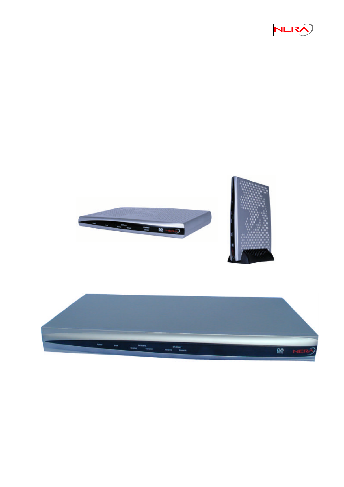
Figure 1: Nera SatLink 1000 Indoor Unit (IDU)
Figure 2: Nera SatLink 1900/1901/1910 Indoor Unit (IDU)
7
Page 8
Nera SatLink Terminal User Guide
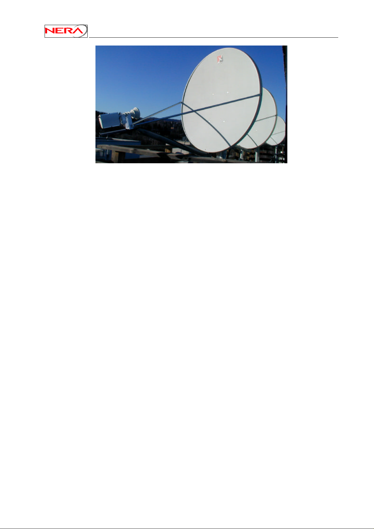
Figure 3: Nera SatLink Outdoor Unit (ODU)
1.1 This User Guide
This User Guide is intended for DVB professionals, such as service providers and installers. Therefore, it
does not contain information for non-professional users, such as given in the user manuals of consumer
electronics products.
This information given pertains to the following software (SW) and hardware (HW) versions and
releases:
• Nera SatLink Boot loader, P/N 101225, SW build 1.8.0.2 and later
• Nera SatLink DVB-RCS Terminal Software, P/N 101224, version 8.0.0 and later
• Nera SatLink 1000, P/N 103346
• Nera SatLink 1900, P/N 100715
• Nera SatLink 1901, P/N 100105
• Invacom LNB/OMT SPV - 1SM, P/N 100816
• Nera SatLink 3000, P/N 100716
• Norsat transmitter 1010/1020XRT, P/N 101338
• Invacom transmitter TUL-204, P/N 104041
• Channel Master Type 960 - 0.96m Antenna, P/N 100883
• Channel Master Type 123 - 1.2m Antenna, P/N 100882
• Channel Master Type 184 - 1.80m Antenna, P/N 104216
• Raven 0.80 x 0.90 antenna, P/N 101391
• Visiosat Tx/Rx 75cm Offset Antenna, P/N 104213
• Visiosat Tx/Rx 90cm Gregorian Offset Antenna, P/N 103044
1.2 Configuration overview
Like all DVB-RCS terminals, the Nera SatLink Terminal must be configured before it can communicate
via the satellite to and from the gateway in the Hub station. There are two aspects of configuration:
• DVB-RCS return link parameters are set from the gateway via the forward link each time the
terminal logs on to the gateway.
• Terminal specific parameters are normally configured during installation. Typically, they include the
parameters for the initial forward link acquisition, parameters describing the outdoor unit equipment
to be used, the IP routing parameters, as well as terminal position, desired population id, and selected
transmitted EIRP on the return link.
A default configuration specifying most of these parameters usually is pre-loaded on each Nera SatLink
Terminal, either in the factory or by the service provider. It is hence normally only necessary to configure
the Forward link frequency and symbol rate, population ID, IP parameters, the SatLink terminal position,
8
Page 9

Nera SatLink Terminal User Guide
and the wanted EIRP for each single terminal. For the current release the following options are supported
for configuration:
• Command Line Interface
- Via RS232/HyperTerminal (utility under Windows)
- Telnet (terminal-to-terminal remote host protocol), either from local LAN or the Satellite
interface (the Gateway).
• Web-interface from local LAN
9
Page 10

2. Unpacking
Check that the following items are in the box received, then unpack.
• SatLink 1000, 1900 or 1901
• Foot for vertical placement (SatLink 1000 only)
• Power supply (SatLink 1000 only)
• Mains cord
• Brackets for 19” rack mounting (SatLink 1900/1901 only)
• CD with documentation
3. Installation
3.1 Before installation
3.1.1 Safety
Follow these guidelines to ensure general safety:
Nera SatLink Terminal User Guide
• Always comply with national and local electrical codes.
• Keep the installation area clear and dust free during and after installation.
• Keep tools and all components away from walk areas.
• Do not wear loose clothing, jewellery (including rings and chains), or other items that might get
caught on the IDU, the ODU or the interconnecting cables.
• Do not work on the system or connect or disconnect cables during lightning storms.
Follow these guidelines when working with electrical equipment:
• Disconnect all power and external cables before installing or removing a SatLink Terminal.
• Do not work alone when potentially hazardous conditions exist.
• Never assume that power has been disconnected from a circuit; always check.
• Do not act in any way that creates a potential hazard to people or makes the equipment unsafe.
• Never install equipment that appears damaged.
• Carefully examine your work area for possible hazards such as moist floors, unearthed mains
extension cables and missing protective earths.
Should an electrical accident occur:
• Be cautious – do not become a victim yourself.
• Turn off electrical power to the system.
• If possible, send another person to get medical aid. Otherwise, assess the condition of the victim and
then call for help.
• Determine if the victim needs artificial respiration or external cardiac compressions; then take
appropriate action.
3.1.2 Site requirements
The Nera SatLink Terminal shall be connected to the mains 110/230 VAC, 50-60Hz.
3.1.3 Network
The Nera SatLink 1900/1901 provides an autodetect interface to a 10/100T Ethernet via an RJ45
connector.
10
Page 11
Nera SatLink Terminal User Guide
3.2 Front and back panels
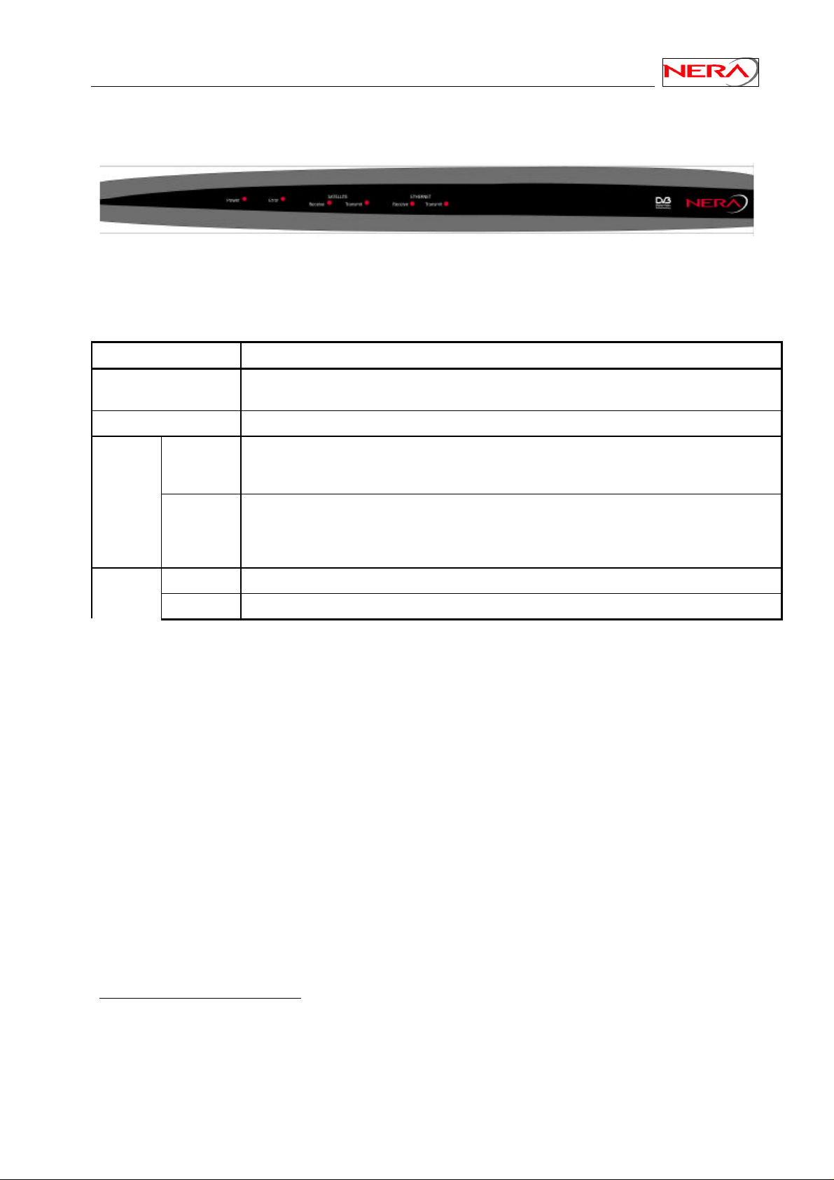
1
Figure 4: SatLink 1900/1901 Front panel.
Table 1: Font-panel LEDs
LED Colour, indicates
Power Blue, steady on when power switch is on and unit is powered. Blinks when the software is
loading.
Error Red, steady on when an error event occurs; steady on during reboot.
Satellite Receive Blue, blinks when the receiver is searching for the carrier.
Steady on when receiver is on and functioning properly.
Blinks when IP packets are received from the Satellite Interface (the Gateway).
Transmit Blue, blinks fast when a continuous wave (CW) is transmitted
Blinks slowly when the terminal is logging on to the DVB-RCS Gateway.
Steady on when the terminal is logged on to the DVB-RCS gateway.
Blinks when IP packets are transmitted to the Satellite Interface (the Gateway).
Ethernet2Receive Blue, on when Ethernet packets from the local network are being received.
Transmit Blue, on when Ethernet packets are sent to the local network.
1
The front and back panels are slightly different for SatLink 1000 and 1910.
2
On SatLink 1000 and 1910 there is only one Ethernet LED which on when connection to another
Ethernet device is established and blinks when there is traffic
11
Page 12
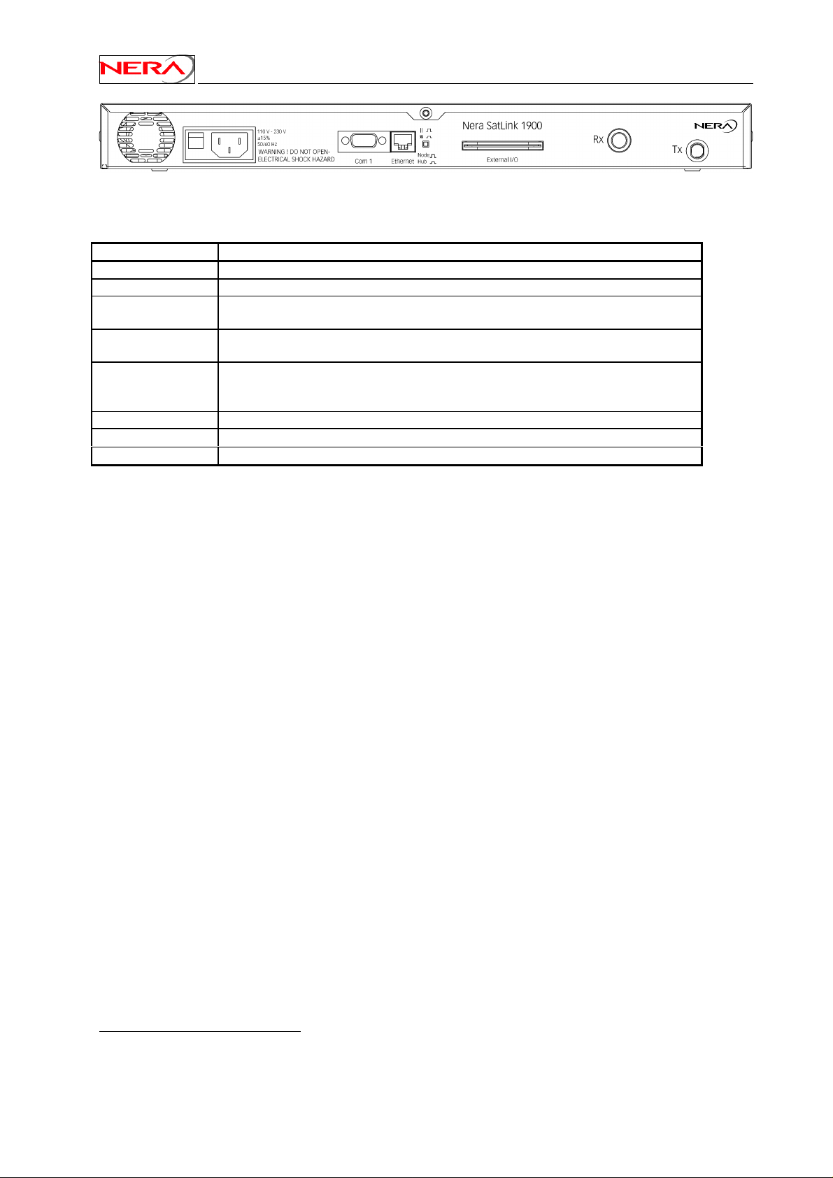
Figure 5: SatLink 1900/1901 Back-panel
Table 2: Back-panel connectors and switches.
Item Description
On/off switch Mains power on (1) or off (0).
Mains Connector
COM1
Connector
Ethernet
Connector
Node/Hub
Push-button toggle
External I/O Not used
Rx coaxial jack
Tx coaxial jack
3
Standard recessed plug for Mains cord.
Nine-pin connector for connecting CLI interface to a computer serial RS232
interface.
RJ45 connector for IP traffic to connect to a PC, Ethernet switch, IP router etc.
4
10BASE-T or 100BASE-T modes are detected automatically.
Selects HUB or NODE configuration of the Ethernet port. NODE normally is used
when connecting to an Ethernet switch or Ethernet hub, while HUB is used when
connecting directly to a single PC.
Coaxial 75 Ω F-type jack for the cable to the ODU receiver.
Coaxial 75 Ω F-type jack for the cable to the ODU transmitter.
Nera SatLink Terminal User Guide
3
The power connector for SatLink 1000 is a 24V DC connector as the SatLink 1000 is equipped with an
external power supply.
4
Not present on SatLink 1000 and 1910 which auto-detects if Hub or Node mode shall be used.
12
Page 13
Nera SatLink Terminal User Guide
3.3 IDU Installation
3.3.1 On desktop or shelf
Place the Nera SatLink Terminal on a flat, stable surface, such as a desktop or shelf, close to the PC or
network device to which it will be connected. Keep its top, bottom and all sides unobstructed to ensure
free airflow. Rubber feet on the bottom provide adequate clearance. Ensure that there is at least 10 cm
clearance at the back to allow room for cable connections.
3.3.2 In rack
Warning: The rack or cabinet should be properly secured to prevent tipping. Equipment installed
in a rack or cabinet should be mounted as low as possible, with the heaviest units lower down, and
lighter units toward the top.
Precautions:
• Ensure that the mains circuits are properly earthed and use the mains cord supplied with the
SatLink Terminal to connect it to the mains outlet.
• If your installation requires a different mains cord than the one supplied, ensure that the cord used is
certified as indicated by the stamped or embossed logo of the electrical safety authority in your
country.
• If the on/off switch on the back panel is difficult to reach when the unit is fitted in the rack, ensure
that the mains outlet into which it is plugged can be reached so it may be unplugged if need be.
• Ensure that the unit does not overload the mains circuit, wiring or over-current protection. To
determine the possibility of overloading the supply circuits, add together the ampere ratings of all
devices installed on the same circuit as the Nera SatLink Terminal and compare the total with the
rating limit for the circuit. The maximum ampere ratings are usually printed on units near their mains
connectors.
• Do not install the Nera SatLink Terminal in a location where the operating ambient temperature may
exceed 45°C.
• Ensure that the airflow around the sides and back of the router is not restricted.
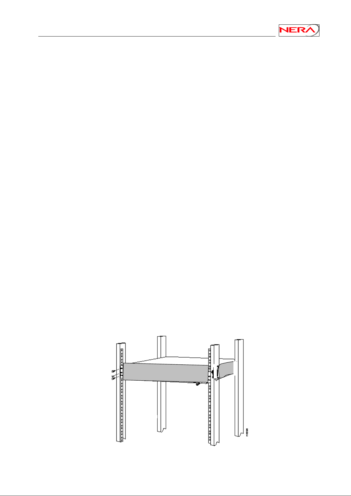
The Nera SatLink 1900/1901/1910 can be mounted in any EIA-standard 19-inch telecommunications rack
or cabinet. The Nera SatLink 1000 needs to be placed on a shelf is it shall b e placed in a rack.
Use a Torx screwdriver and attach the mounting brackets to the router with the screws supplied. Hold the
unit securely, brackets attached, and move it vertically until rack holes line up with the bracket notches,
then insert and tighten the four screws holding the brackets to the rack.
Figure 6: Rack Mounting
13
Page 14

Nera SatLink Terminal User Guide
3.4 ODU installation
Install the ODU as described in Appendix G and references [1], [2], [3], [4]and [5].
3.5 Interface connections
3.5.1 Rx/Tx cables between IDU and ODU
The coaxial cables from the ODU are connected to the type F coaxial jacks on the back panel of the Nera
SatLink Terminal. See also document Cable specification 102317.
• Connect one coaxial cable from the ODU Tx module input to the jack marked Tx. Do not connect
the Tx cable before the initial configuration of the Nera SatLink Terminal is performed to
ensure that incorrect or hazardous signals are not sent to the satellite.
• Connect one coaxial cable from the LNB to the port marked Rx on the back panel.
Note
Use only 75 O coaxial cables fitted with type F plugs for the Rx and Tx cables
5
Note
Do not connect and disconnect the coaxial cables with power connected to the Nera SatLink
Terminal.
Hint
Before connecting the coaxial cables to the jacks on the back panel, perform a loop test by
connecting the cables together with a splice at the ODU and performing a continuity test at their
IDU ends.
Hint
Using different colour marking on the Tx and Rx coaxial cables reduces the probability for
interchanging the cables.
3.5.2 Ethernet connection to a Local Area Network (LAN)
The Nera SatLink Terminal may be connected to a single PC or to a network via the RJ-45 Ethernet jack
on the back panel.
• Plug one end of the Ethernet cable into the RJ-45 jack on the back panel.
• Plug the other end of the Ethernet cable into the RJ-45 jack a Local Area Network (LAN) device such
as an Ethernet hub, switch or router, according to its manufacturer’s instructions.
For the Nera SatLink 1900 and 1901 toggle the back panel push button to configure either Ethernet HUB
or NODE modes. Toggle to NODE when connecting to an Ethernet switch or an Ethernet hub, and toggle
to HUB when connecting to a single PC.
For the Nera SatLink 1000 and 1910 there is no push button on the back panel as Ethernet HUB or
NODE mode will be auto-detected and the correct mode chosen automatically.
3.5.3 Mains connection
The Nera SatLink 1900/1901/1910 has an internal power supply and consequently is connected directly to
a 110/230 VAC 50/60Hz outlet using a standard 230 VAC mains cord.
5
When using the Norsat 1010/1020XRT BUC a water-proof F-to-N adapter must be mounted between
the cable and the BUC input connector.
14
Page 15

Nera SatLink Terminal User Guide
3.5.4 Power supply
The Nera SatLink 1000 has an external power supply that is connected to a 110/230 VAC 50/60Hz outlet
using a standard 230 VAC mains cord.
Warning: The Nera SatLink 1000 must only be connected to the external power supply that is
approved by Nera, P/N 104170 (LEI-S2425D / Model No. STD-2425)
Use of another power supply may void warranty.
15
Page 16
Nera SatLink Terminal User Guide
4. PC configuration
4.1 Dynamic IP configuration of PCs connected to the Nera SatLink Terminal
LAN
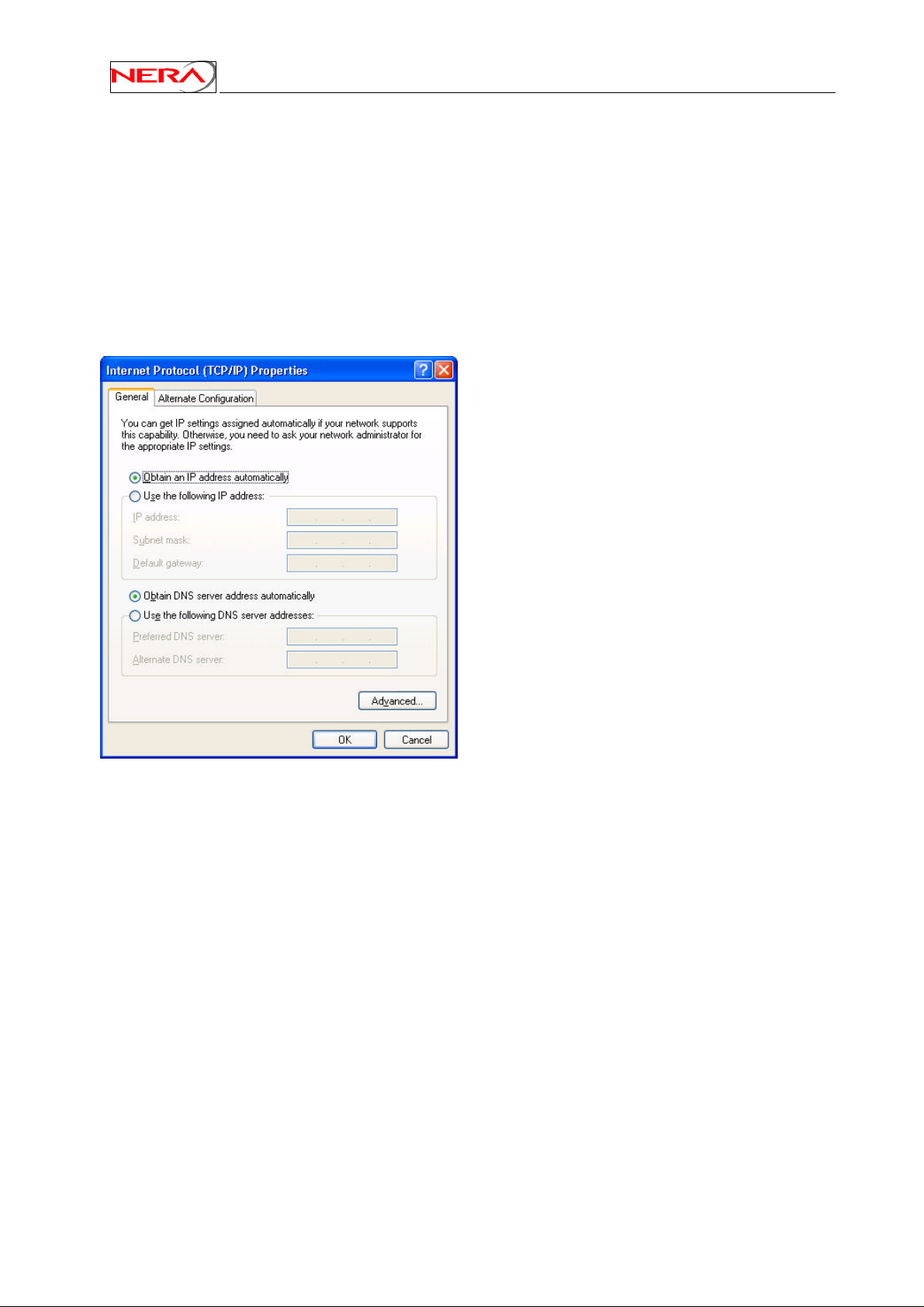
By default the DHCP server in the Nera SatLink Terminal is enabled, and all PCs connected to the Nera
SatLink LAN can automatically retrieve their IP configuration from the DHCP server. The user should
verify that the Window clients are configured to obtain an IP address and DNS server address
automatically. The screen display shown below is from a Windows XP host. Displays in other versions of
Windows may differ slightly.
Figure 7: TCP/IP properties
16
Page 17
Nera SatLink Terminal User Guide
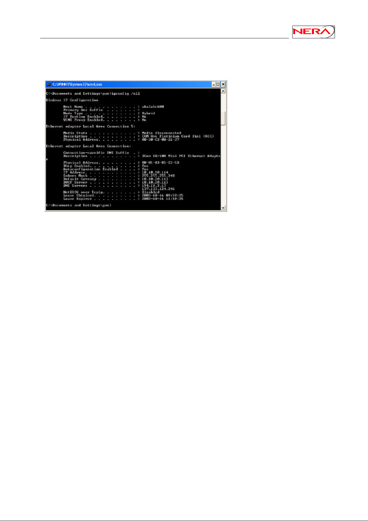
From an MS-DOS window, the user may type ipconfig /all command to verify that the computer has
received correct configuration parameters from the DHCP server like IP address, subnet mask, default
Gateway, DNS servers and lease time.
Figure 8: ipconfig /all print out from an MS-DOS window
4.2 Static IP configuration of PCs connected to the Nera SatLink Terminal LAN
All PCs attached to the Nera SatLink Terminal LAN should be configured with static IP addresses when
the DHCP server in the SatLink Terminal is not enabled. The IP configuration parameters to use for PCs
connected to the Nera SatLink Terminal LAN are supplied from the system operator or service provider.
The screen displays shown below are in Windows 2000. Displays in other versions of Windows may
differ slightly.
4.2.1 Configure a Windows NT client
Use Windows Start menu, Settings, Control panel, Network, Protocols, Select TCP/IP, Properties,
Specify IP address. For instance, a host may have the following configuration; IP address 10.10.10.2,
Subnet mask 255.255.255.248 and default gateway 10.10.10.1, where the IP address of the default
gateway should be the IP address of the Nera SatLink Terminal LAN interface.
The DNS address can also be set in this menu.
The PC may have to be restarted to activate the new settings.
4.2.2 Configure a Windows 2000 client
Use Windows Start menu, Settings, Control panel, Network and dialup connections, Right click
Ethernet/LAN, Properties, Select Internet protocol (TCP/IP), Properties, Use the follow IP addresses. For
instance, a host can have the following configuration; IP address 10.10.10.58, Subnet mask
255.255.255.248 and default gateway 10.10.10.57.
17
Page 18
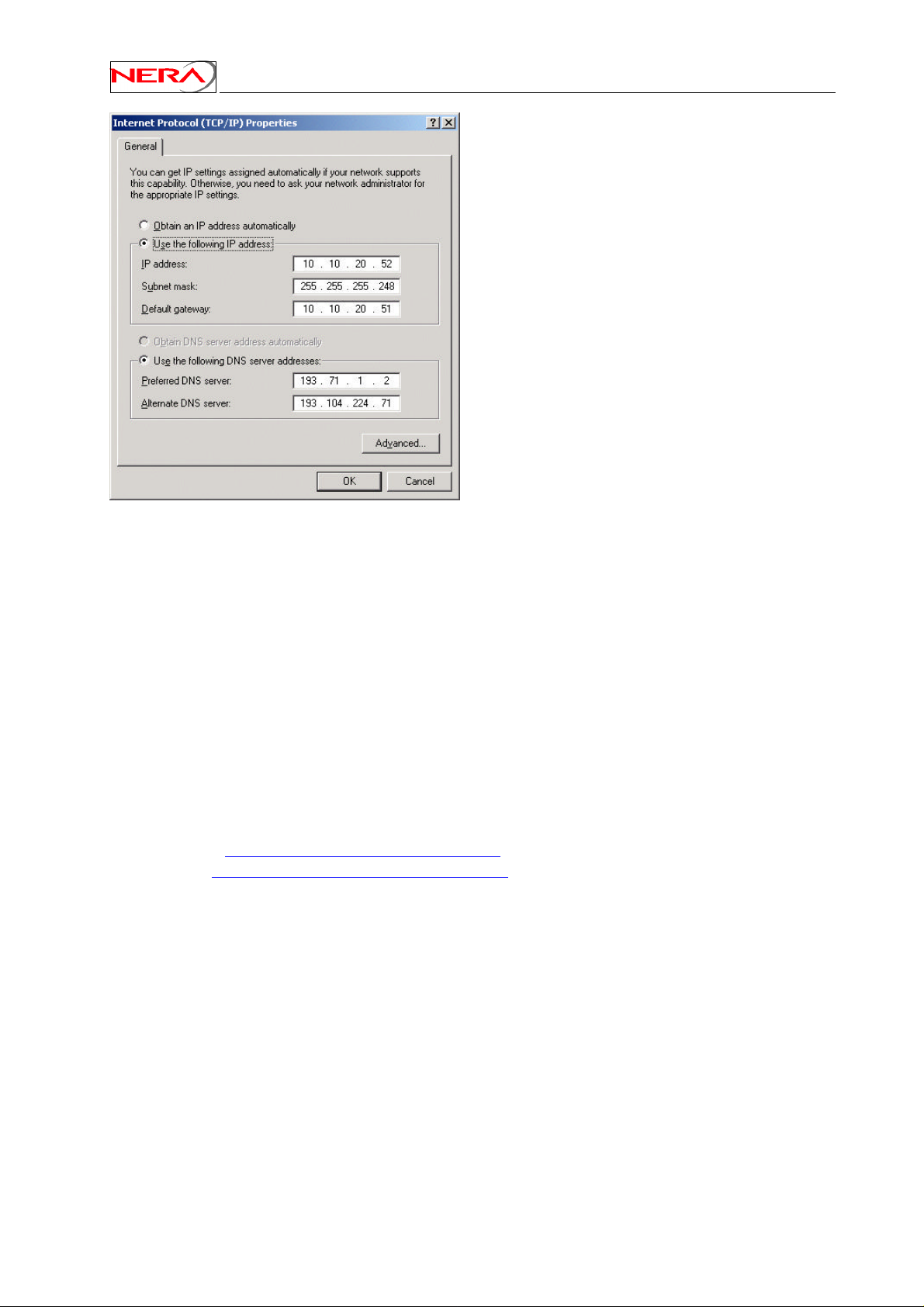
Figure 9: Configuring Windows TCP/IP properties
Nera SatLink Terminal User Guide
The DNS address can also be set in this menu.
4.3 Tuning of TCP parameters
TCP is a packet-based protocol where data is transmitted in variable sized blocks. The TCP Receive
Window has a default value of 8 kB in Windows 95/98/NT and about 16 kB in Windows ME/2000/XP,
which is adequate for relatively slow dialup modems and high-speed networks with relatively low latency
(round-trip delay less than about100 ms). Increasing the TCP Receive Window above the default setting
can substantially improve the throughput on satellite connections were the round trip delay typically is in
the order of 600 ms.
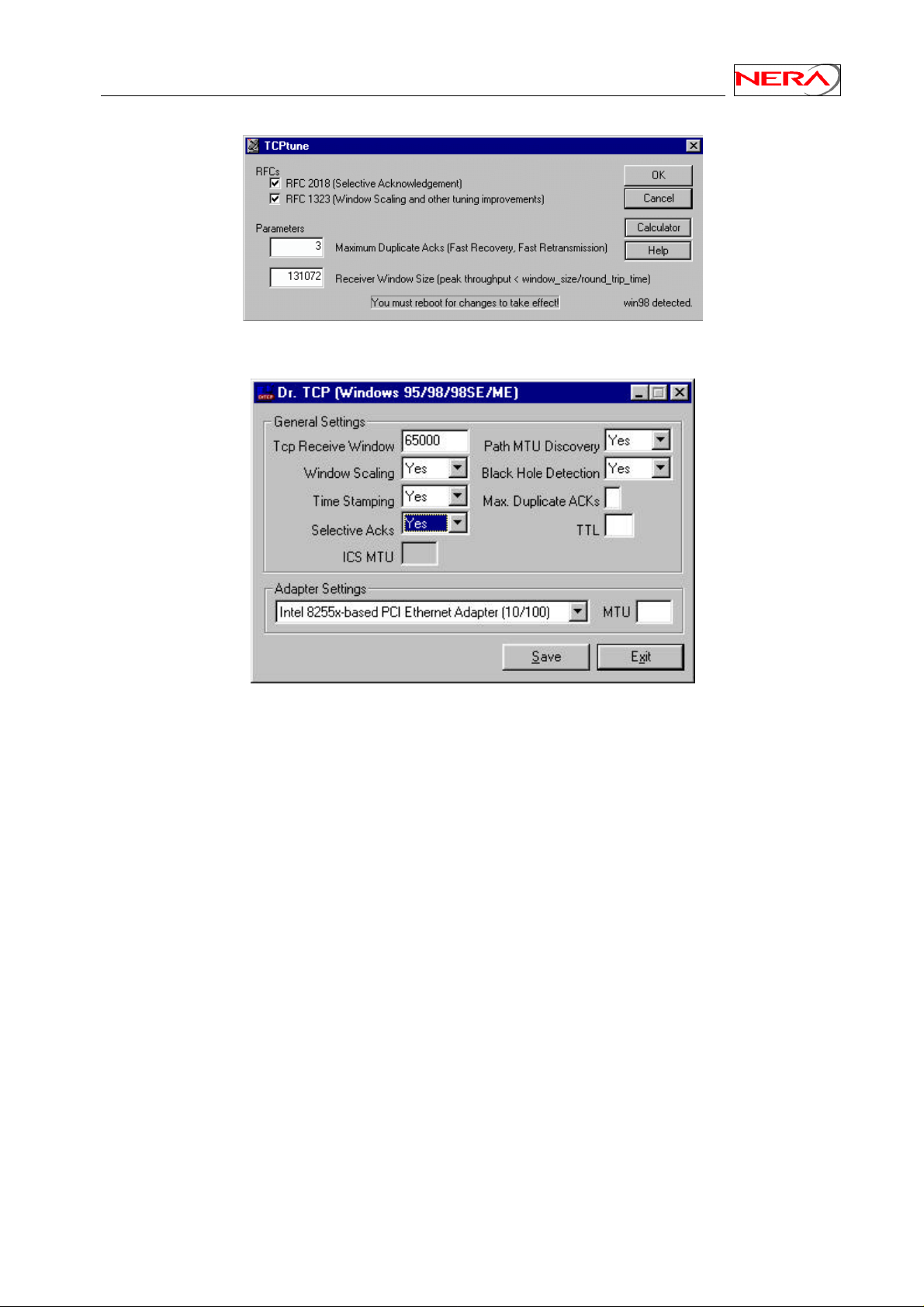
Some free tools are available on the Internet to “tweak” various TCP/IP network settings that affect
downstream performances. They basically provide a short-cut to modify registries of Windows based
PCs.
• Tcp Tune at http://moat.nlanr.net/Software/TCPtune/ and
• Dr. Tcp at http://www.dslreports.com/front/drtcp.html are widely used freeware.
Microsoft has confirmed a TCP/IP transmission bug in Windows 95,98 and NT that can adversely affect
upload throughput over high-delay networks. However, the problem is corrected in NT Service Pack 6.
Windows NT, Windows 95 have older TCP/IP stacks that neither support large windows, nor selective
acknowledgement. Reportedly there are some patches available to fix this for Windows 95. The window
size should be increased to 65kB.
Windows 98/ME/2000/XP support selective acknowledgement, window scaling and large windows. The
default window size for Windows 98 is 8k. The Dr. TCP tool should be used to set large receive buffers
(65 kB or above), maximum TCP receive windows shall be set to 115000, as well as enabling windows
scaling/time stamps (RFC1323) and SACK (RFC 2018) functionality.
18
Page 19
Nera SatLink Terminal User Guide
Figure 10: TCPTune utility
Figure 11: Dr. TCP utility
19
Page 20
Nera SatLink Terminal User Guide
5. Using the Command Line Interface of the SatLink
Terminal
The command line interface can be accessed via either Telnet or the RS-232 port for management of the
Nera SatLink Terminal as well as for showing status and reports.
5.1 Start-up sequence
When turning on the Nera SatLink Terminal first the Boot SW is loaded. A message like this is displayed
on the CLI/RS-232 when the boot SW starts. Note that Telnet is not available before the application has
been started.:
Nera SatLink boot-loader
- SW Product ID 101225, Revision 1.8.0.2
File system initialised
Press return to login
Press return within 10 seconds to display the login-prompt for entering the boot-load. See Appendix I for
further details about the boot SW.
After the timer has expired, the DVB-RCS application will be loaded. The message Loading
application will be shown when the application starts to load.
When the DVB-RCS application starts to run a message like this will be shown:
Nera SatLink 1900
- Main Board ID QROF2199282, Revision 6.2
- SW ID 101224, Revision 7.0.1 Build 21
The application will then initialise the file system, restore all configuration parameters from flash, do
initial configuration, and start the DVB-RCS receiver and transmitter if these are configured to start
automatically. Use the CLI commands dvb tx autostart and dvb rx autostart to configure the
DVB transmitter and receiver to start automatically when the DVB-RCS application is started.
The following messages on CLI shows when the Nera SatLink Terminal has successfully restored all
configuration parameters from the MIB (from the configuration file on the flash file system), when lock
on the forward link is achieved, and when successful DVB-RCS logon has been achieved:
State : CLI message
Configuration completed
Lock on forward Link achieved
Successful logon
: Retrieving configuration....done
: Forward link up
: Return link up
Two-way link established
20
Page 21
Nera SatLink Terminal User Guide
5.2 CLI users access rights
5 levels are supported:
• Level 1: super user
• Level 2: installer
• Level 3-5: end users
When shipped from the factory there are two users available in the Nera SatLink Terminal:
User name Factory default password6Privilege level
root nera 1
install satlink 2
When accessing the CLI via RS-232, if the login prompt is not displayed type ENTER. The login prompt
Login: should then be displayed. Then login with e.g. the root user:
Login: root
Password: nera
When the command prompt is displayed you will now have super user access to the CLI.
New users may be added with the CLI command user add, existing users deleted with the CLI
command user del, and the password of the current user or users with lover privilege levels can be
changed with the CLI command user passwd6. To list all defined users with lower privilege level than
the user currently logged in, use the CLI command user show. Type ? user to get further help on the
user commands.
5.3 Online help
In the CLI a list of available commands can be displayed by typing ? <ENTER> (question mark and the
ENTER). The CLI command groups will then be shown:
Example:
# ?
To list the commands in a sub-menu type '? <sub-menu>'
device : Device configuration
dvb : Configure DVB interface
eth : Show Ethernet status
ip : IP configuration
misc : Miscellaneous commands
odu : ODU configuration
sw : Software upgrade configuration
user : User configuration
log : Event log
#
6
Note that older version of the SatLink 1900 (revision 1.x) may have the factory default password
admin123 for the root user. The root password on these terminals can not be changed by the passwd
command. Contact Nera if there is a strong need to change the root password on such a terminal.
21
Page 22

Nera SatLink Terminal User Guide
To display the available commands within one command group type ? <group>.
Example:
# ? ip
For detailed help on a command type '? ip <command>'
qos : sub menu for configuration of Return Link QoS
addroute : ip addroute <destaddr> <netmask> <next hop> <ifnum>
delroute : ip delroute <destaddr> <netmask> <next hop>
set : ip set <ifnum> <ipaddr> <mask>
show : ip show [-mcast]
#
To get further help on a specific CLI command type ? <group> <cmd>.
Example:
# ? ip set
USAGE:
ip set <ifnum> <ipaddr> <mask>
ifnum Interface number (1=LAN, 3=Satellite)
ipaddr IP address for the interface
mask Netmask for the interface
Set the IP address and subnet mask for the specified interface
Example:
ip set 1 10.10.1.1 255.255.255.248 will set the LAN IP address to
10.10.1.1 and the LAN netmask to
255.255.255.248
See also:
ip show, ip addroute, ip delroute
#
5.4 Logging of events
The Nera SatLink Terminal logs certain events to a log stored in RAM. See Appendix M for a list of the
different events and what action that need to be taken for the different events. Use the CLI command log
show to show the log from memory.
The events are divided in four different severity levels:
0. Minor
1. Normal
2. Major
3. Critical
Events with severity level Major will normally cause disruption in the data transfer, while events with
severity level Critical normally will require user intervention in order to restore the data communication
with the DVB-RCS gateway.
To have access to the log of events also after the terminal software has been rebooted, the event above a
specified severity level can be logged to file. Use the CLI command log file to enable logging of
events to file, set the minimum severity level of events that shall be logged to file and set the maximum
size for the logfile. The factory default settings are that logging of events with severity level Major and
Critical to file is enabled.
22
Page 23
Nera SatLink Terminal User Guide
5.5 CLI command summary
The available CLI commands are listed below.
CLI commands Available in
Boot
SW
ping <ipaddr> x x 5
del <filename> x x 2
ren <filename1> <filename2> x x 2
dir [ext] x x 5
type <filename> x x 5
save config x 5
dload <filename> <ipaddr> x x 2
upload <filename> <ipaddr> x x 2
Restart x x 5
Logout x x 5
? [sub-menu] [cmd] x x 5
device name <name> x 2
device contact <contact> x 2
device location <location> x 2
device show x 5
device snmp community <name> <ro|rw>
[<ipaddr> <mask>]
device snmp delcommunity <name> x 1
device snmp show x 5
dvb tx autostart <on|off|traffic> [<timeout>] x 2
dvb tx calibrate [<freq>] x 2
dvb tx cw <on|off> 0 [<pow> [<freq>]] x 2
dvb tx cwfreq <freq> x 2
dvb tx eirp <eirp> x 2
dvb tx logoff x 2
dvb tx logon x 2
dvb tx outpow <pow> x 2
dvb tx show [-capacity] x 5
dvb rx autostart <on|off> x 2
dvb rx start x 2
dvb rx stop x 2
dvb rx pol <value> x 2
dvb rx freq <freq> x 2
dvb rx symbrate <symbrate> x 2
dvb rx show x 5
dvb pos lat <deg> <min> <mindec> <dir> x 2
dvb pos long <deg> <min> <mindec> <dir> x 2
dvb pos alt <height> x 2
dvb pos show x 5
dvb pid <flag> 0 <pid> x 1
dvb dispid x 5
dvb timeout <type> <value> x 1
dvb addroute <destaddr> <netmask> 0 MPG 0
<pid> [<macaddr>]
dvb delroute <destaddr> <netmask> x 1
dvb showroute x 5
dvb showtimeout x 5
dvb popid <id> x 2
eth show x 5
Available in
Application
SW
x 1
x 1
User
Privilege
Level
23
Page 24
Nera SatLink Terminal User Guide
CLI commands Available in
Boot
SW
ip addroute <destaddr> <netmask> <next hop>
x x 2
Available in
Application
SW
User
Privilege
Level
<ifnum>
ip delroute <destaddr> <netmask> <next hop> x x 2
ip qos mask <index> <group> {{+|-}<tag>
x 2
<tag-parms>}+
ip qos show x 5
ip set <ifnum> <ipaddr> <mask> x x 2
ip show [-mcast] x x 5
ip nat <enable|disable|show>
ip dhcp <enable|disable>
ip dhcp show
7
ip dhcp leasetime <time> [unit]
7
7
7
ip dhcp dns <primary> <secondary>
ip dhcp exclude <no>
7
ip gre add <destaddr> <netmask>
<tunnelipaddr>
ip gre del <ifnum>
ip gre show
7
7
7
log file <enable|disable>
7
x 2
X 3
X 5
X 3
X 3
X 3
X 2
X 2
X 5
X 5
[<severity> [<filesize>]]
log show X 5
odu lnb <type> X 2
odu txtype <type> X 2
odu antenna <type> X 2
odu show X 5
sw license <feature> <key> X 2
sw mcast <value> [<pid>] [<addr>] [<port>] X 2
sw upgrade [-default] [<filename>
X 2
[<tftp-ip-addr>]]
sw restore X 2
sw show X 5
user add <loginname> <passwd>
x X 5
[privilege level]
user del <loginname> x X 5
user passwd {loginname | oldpasswd}
x X 5
<newpasswd>
user show x X 5
7
CLI commands is available only when license for software option is installed.
24
Page 25

Nera SatLink Terminal User Guide
6. Nera SatLink Terminal configuration
Before powering up the Nera SatLink Terminal for the first time, ensure that the Tx coaxial cable from
the Nera SatLink Terminal to the ODU is disconnected to avoid that incorrect or potentially damaging
signals are sent to the satellite. Follow all the procedures below when installing the Nera SatLink
Terminal and lining up the ODU.
6.1 Power on and logon
1) To view the boot processes of the Nera SatLink Terminal, please connect a terminal emulator to the
serial interface as described in Appendix B. Otherwise go to step 2.
2) Turn on the power of the Nera SatLink Terminal.
3) Wait for the application software to be loaded and activated (typically takes 1-1.5 minutes).
The power led on the front of the Nera SatLink Terminal will blink8 when the SW is booting and will
stay on when the SW has successfully started. If watching the boot process on the RS-232 output, a
printout similar to this will be displayed when the SW has booted.
Nera SatLink 1900
– Main Board ID QROF2199282, Revision R6.2
- SW ID 101224, Revision 7.0.1 Build 21
File system initialised
Ethernet Interface MAC Address : 00:60:c0:2f:43:a7
DVB Interface MAC Address : 00:60:c0:2f:43:a7
Retrieving configuration....done
4) Start a Telnet session to the Nera SatLink Terminal. Please note that Local Echo must be enabled in
the Telnet Client. Recommended Telnet clients are Terra Term (see Appendix D), PuTTY9, and the
built in Telnet client in Windows (not for Windows XP where Local Echo does not seem to work).
If the Nera SatLink Terminal does not seem to be reachable from the LAN just after power-on this
may be due to slow update of the ARP cache on the PC. Then verify that the Nera SatLink Terminal
is registered in the PC’s ARP cache by using the MS-DOS command arp –a
Use the Nera SatLink Terminal’s Satellite Interface (DVB) IP address when using Telnet over the
satellite link (from the Gateway), and the Nera SatLink Terminal’s LAN (Ethernet) IP address when
using Telnet from the local LAN.
When shipped from the factory the SatLink Terminal LAN (Ethernet) IP-address10 is set to
192.168.0.1 and the subnet mask to 255.255.255.0. If the Nera SatLink Terminal LAN (Ethernet) IPaddress is not known, one must use CLI via RS-232 to do the initial configuration.
The Nera SatLink Terminal can handle at most three simultaneous Telnet connections including
aborted connections. The Telnet session will be automatically terminated after 20 minutes without
activity. If a Telnet session is refused this can be due to all three connections being aborted. Please
wait until the timeout has expired and try again.
8
In older SatLink 1900 versions (Hardware revision 1.2 and earlier – main board revision R4 an R5.1)
and for SW build 1.7.0.6 an earlier of the boot software, the power led will light continuously also when
the SW is booting. On these terminals one short blink in the Satellite receive/transmit diodes shows that
the SW has booted successfully.
9
http://www.chiark.greenend.org.uk/~sgtatham/putty/download.html
10
The SatLink 1900 and 1901 normally has the LAN IP address set to 10.10.10.10 and the subnet mask to
255.0.0.0 when shipped from the factory.
25
Page 26
Nera SatLink Terminal User Guide
5) Login as the administrator user root with the factory default password nera :
Login: root
Password: nera
Nera SatLink 1900
– Main board ID QROF2199282, Revision R6.2
- SW ID 101224, Revision 7.0.1 Build 21
11
Note that one must press Enter once to get the login-prompt to display if using the CLI via RS-232.
6) The Nera SatLink Terminal should now be ready to be configured as described in the following sub-
sections.
6.2 Initial configuration of parameters
6.2.1 IP configuration
The DVB-RCS system operator manages all IP addresses in the DVB-RCS system including the DVB
interface IP address and the LAN IP addresses of all DVB-RCS terminals. Please make sure that the IP
addresses and netmasks are entered exactly as specified by the DVB-RCS system operator, as any
deviation normally will result in that the Nera SatLink Terminal will not be able to communicate
correctly with the IP network of the DVB-RCS system operator.
1) Set the LAN IP address of the unit
– Enter the CLI command ip set 1 <aaa.bbb.ccc.ddd> <eee.fff.ggg.hhh>
where <aaa.bbb.ccc.ddd> is the IP address and <eee.fff.ggg.hhh> the netmask.
Example:
# ip set 1 10.10.20.1 255.255.255.248
2) Set the DVB IP address (Satellite interface) of the unit:
– Enter the CLI command ip set 3 <aaa.bbb.ccc.ddd> <eee.fff.ggg.hhh>
where <aaa.bbb.ccc.ddd> is the IP address and <eee.fff.ggg.hhh> the netmask.
Example:
# ip set 3 10.10.21.1 255.255.255.0
11
nera is the factory default setting for the password. The password might have been changed after
shipment from the factory.
26
Page 27

Nera SatLink Terminal User Guide
3) Verify that the IP addresses and netmasks are set correctly:
– Enter the CLI command ip show
Example:
If the values above have been configured the ip show command shall give the following result.
(Interface 1 is the LAN interface, interface 2 is not used, and interface 3 is the DVB (satellite)
interface):
# ip show
Interfaces
If IPAddress SubnetMask BroadCastAddr MTU Alias AdminStatus
1 10.10.20.1 255.255.255.248 10.10.20.7 1500 eth0 1
2 N/A N/A N/A 4074 air0 1
3 10.10.21.1 255.255.255.0 192.168.255.255 4074 dvb0 1
Interface Statistics
------------- Input ----------------- ------------- Output ---------------If UCast NUCast Disc Octets UCast NUCast Disc Octets
1 0 9 0 1196 0 3 0 120
2 0 0 0 0 0 0 0 0
3 0 0 0 0 0 0 0 0
Routing Table
DestMask RouteMask NextHop If
0.0.0.0 0.0.0.0 10.10.21.254 3
10.10.20.0 255.255.255.248 0.0.0.0 1
10.10.21.0 255.255.255.0 0.0.0.0 3
#
Ensure that the correct route is defined to the LAN (in this example that the destination mask
10.10.20.0 with route mask 255.255.255.248 is defined for the LAN interface), and that the default
route (Destination mask 0.0.0.0 with route mask 0.0.0.0) is defined for the satellite interface, and has a
valid Next Hop IP address. Please note that for routes to the DVB interface, routing is not based on the
Next Hop IP address. The Next Hop IP address for the default route can therefore be set to any
valid IP address within the DVB interface subnet, except for the Nera SatLink Terminal’s own
DVB interface IP address. Please, always make sure that the next hop IP address for the default route
is neither located on the Nera SatLink Terminal’s own LAN nor is the DVB interface of the SatLink
Terminal. Otherwise it will break the IP connectivity from the Nera SatLink Terminal to the DVB-RCS
gateway
4) Save the IP configuration to Flash
– Enter the CLI command: save config
– Example:
# save config
Saving Configuration. This will take ~20 secs
# Configuration Saved
#
If the prompt sign (#) does not show push enter.
27
Page 28
Nera SatLink Terminal User Guide
6.2.2 ODU parameter configuration
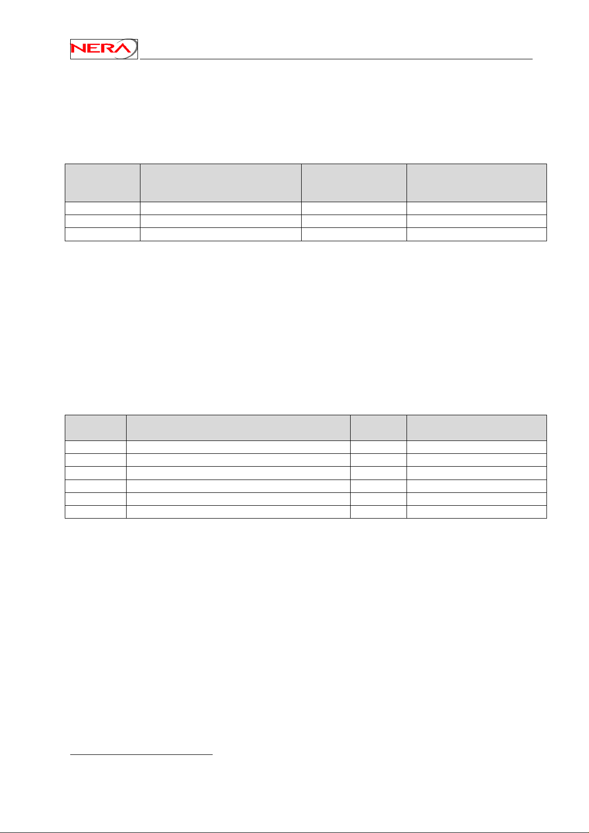
The Nera SatLink Terminal is normally pre-configured for being used together with the Nera SatLink
3000 Transmitter (P/N 100716) and the Invacom LNB/OMT SPV-1 SM (P/N 100816).
Please make sure that the correct ODU transmitter (BUC) type is selected according to the table below as
the return link communication will otherwise not work.
ODU
ODU Transmitter (BUC) Nera P/N HW Revision
Transmitter #
(type)
10 Nera SatLink 3000
100716
5.0 and newer
20 Norsat 1010XRT / 1020XRT 101338 All
30 Invacom TUL-204 104041 All
If an other ODU transmitter (BUC) listed in the table above is to be used, please enter the CLI command
odu txtype <type> where type is the number from the first column in the table above.
Example:
# odu txtype 30
selects the Invacom TUL-204 transmitter. Use the command odu show to view the ODU configuration
parameters.
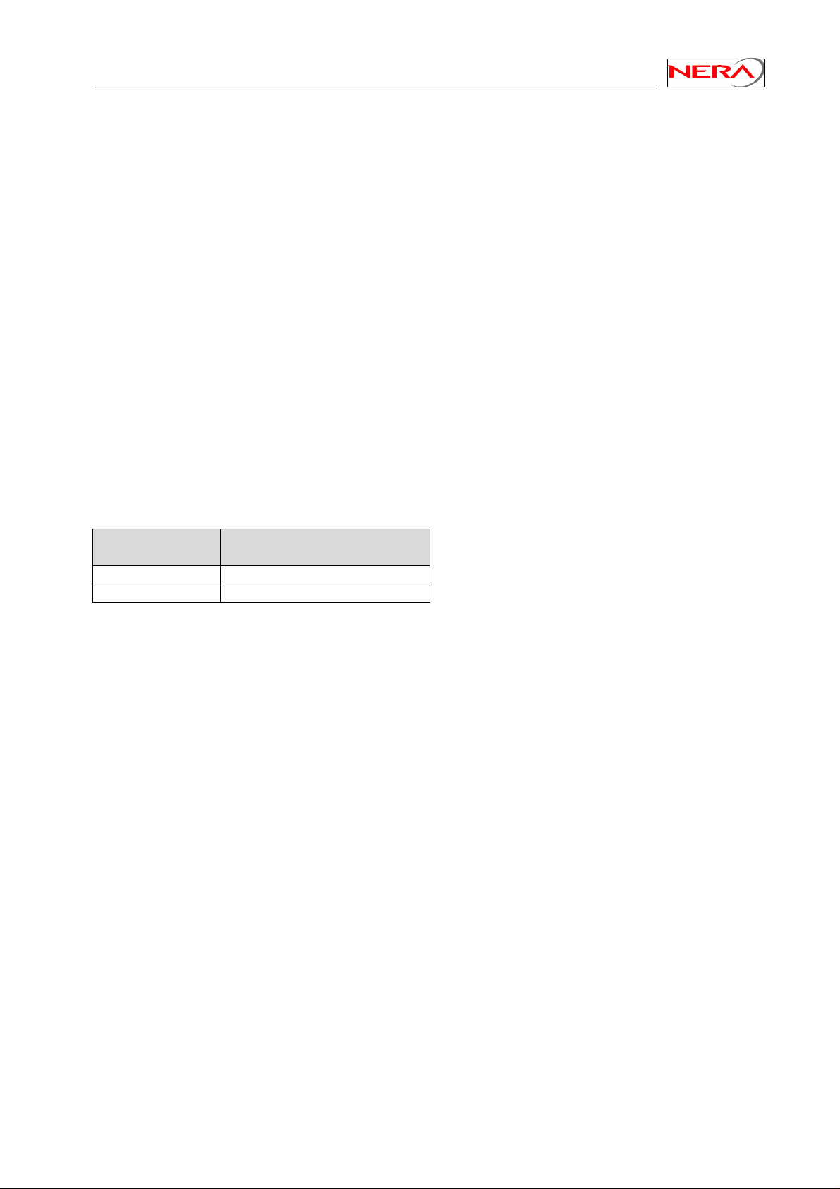
When using the Nera SatLink 3000 ODU transmitter12, the Nera SatLink Terminal must be configured
with the antenna type in use in order to calculate the transmitted EIRP correctly. The following antennas
are supported:
Antenna #
Antenna Size Manufacturers part no:
(type)
2 Channel Master Type 960 96 cm 62-96055-02
1 Channel Master Type 123 120cm 62-12361-02
5 Channel Master Type 184 180cm 62-18452-02
3 Raven G90 80x89cm G090ASAZDGS01
6 Visiosat Tx/Rx 75cm Offset Antenna 75cm
4 Visiosat Tx/Rx 90cm Gregorian Offset Antenna 90cm
The Nera SatLink Terminal is normally pre-configured to use the Channel Master 960 antenna. If another
antenna listed in the table above is to be used, please enter the CLI command odu antenna <type>
where type is the antenna number from the first column in the table above.
Example:
# odu antenna 1
selects the Channel Master 120cm antenna. Use the command odu show to view the ODU configuration
parameters.
12
Not revision 3.0 or older of the SatLink 3000 transmitter
28
Page 29
Nera SatLink Terminal User Guide
Example:
# odu show
Antenna Configuration
--------------------Type Channel Master Type 960 - 96cm
Tx Gain at 14.25 GHz 41.2 dB
ODU Transmitter (BUC) Configuration
----------------------------------Type Nera SatLink 3000
Product ID 0x0000000000
Local oscillator 13.040000 GHz
24V DC supply On
ODU Receiver (LNB) Configuration
-------------------------------Type Invacom SPV-1SM
Local oscillator - High band 10.600000 GHz
Local oscillator - Low band 9.750000 GHz
Oscillator switching frequency 11.700000 GHz
13/18V DC supply On
LO Switching mode 22kHz
The SatLink Terminal can be configured with one of the following LNBs:
ODU LNB #
ODU LNB
(type)
20 Invacom SPV-1SM
30 Zinwell ZK-VJ1
Enter the CLI command # odu lnb <lnbtype> where type is the number from the first column in the
table above to configure the correct LNB.
29
Page 30

Nera SatLink Terminal User Guide
Example:
# odu lnb 20
selects the Invacom SPV-1SM LNB. Use the command odu show to view the ODU configuration
parameters:
# odu show
Antenna Configuration
---------------------
Type Channel Master Type 184 - 1.8m
Tx Gain at 14.25 GHz 47.0 dB
ODU Transmitter (BUC) Configuration
----------------------------------Type Nera SatLink 3000
Product ID 0x0000000000
Local oscillator 13.040000 GHz
24V DC supply On
ODU Receiver (LNB) Configuration
-------------------------------Type Invacom SPV-1SM
Local oscillator - High band 10.600000 GHz
Local oscillator - Low band 9.750000 GHz
Oscillator switching frequency 11.700000 GHz
13/18V DC supply On
LO Switching mode 22kHz
#
Finally save the configuration to flash using the command save config. Please note that the Nera
SatLink Terminal must be restarted for the new configuration to take effect.
6.2.3 Terminal position
In order to calculate the delay to the satellite correctly for the logon burst the Nera SatLink Terminal must
be configured with its own position.
1) Find the position of the location where installing the Nera SatLink Terminal in WGS84 coordinates
using a standard GPS
2) Note that the SatLink Terminal position is entered in degrees, minutes and 1/100 minutes.
Many GPS’es display the position in degrees, minutes, seconds, and optionally 1/100 seconds.
To convert from seconds to 1/100 minutes please use the following formula:
1/100 minutes = (seconds/60) x 100
3) Configure the latitude:
– Enter the CLI command dvb pos lat <deg> <min> <mindec> <dir> where
deg = degrees
min = minutes
mindec = 1/100 minutes
dir = direction. 0 = North. 1= South.
Example:
# dvb pos lat 59 52 17 0
sets the latitude to 59°52.17'N.
30
Page 31

Nera SatLink Terminal User Guide
4) Configure the longitude:
– Enter the CLI command dvb pos long <deg> <min> <mindec> <dir> where
deg = degrees
min = minutes
mindec = 1/100 minutes
dir = direction. 0 = East. 1= West.
Example:
# dvb pos long 10 29 05 0
sets the longitude to 10°29.05'E.
5) Configure the altitude:
– Enter the CLI command dvb pos alt <height> where
height = height in meters
Example:
# dvb pos alt 60
sets the altitude to 60 meters.
6) Verify the Terminal position:
- Enter the CLI command dvb pos show
Example:
# dvb pos show
Latitude : 59°52.17 North
Longitude : 10°29. 5 East
Altitude : 60m
7) Save the Terminal position to Flash
– Enter the CLI command: save config
6.2.4 Forward link parameters
The forward link parameters are used to identify the forward link (outbound link) that is transmitted from
the Gateway to the DVB-RCS terminals. To set the symbol rate and receive frequency for the forward
link to receive, use the following CLI commands:
Set symbol rate : dvb rx symbrate <Rx SymbolRate> (symbol rate in symbols per sec.)
Set frequency : dvb rx freq <RxFrequency> (in kHz)
Verify the settings by typing the CLI command dvb rx show and type save config to save the
configuration.
31
Page 32

Nera SatLink Terminal User Guide
Example:
# dvb rx symbrate 30000000
# dvb rx freq 12591000
# save config
# dvb rx show
Satellite (DVB) RX Configuration
-------------------------------Auto start : Disabled
Frequency : 12.591000 GHz
Symbol rate : 30.000000 Msps
Polarisation : Horizontal
Satellite (DVB) RX Status
-------------------------------State : Off
#
Which shows how to configure the Nera SatLink Terminal to use the following forward link:
• Rx symbol rate: 30.0 Msps
• Rx frequency: 12.591 GHz
Please note that the correct polarisation need not to be configured during terminal installations when
using the Invacom SPV-1SM or Zinwell ZK-VJ1 LNBs. These LNBs are single polarisation only LNBs,
and the receive polarisation is set fixed during installation.
6.2.5 Population ID
The Nera SatLink Terminal will select which group in the DVB-RCS system it belongs to based on the
configured population ID. Set the population ID by using the CLI command dvb popid <id>, where
id is the wanted population ID.
Example:
# dvb popid 2
# save config
# dvb tx show
Satellite (DVB) TX Configuration
-------------------------------Auto start : Disabled
Population ID : 2
IDU output power : -15 dBm
EIRP : 42.0 dBW
Default CW Frequency: 14.488000 GHz
AAL5 Encapsulation : VC MUX
DVB Transmitter Status
---------------------State : Off
#
Which shows how to configure the Nera SatLink Terminal to use population ID 2.
32
Page 33

Nera SatLink Terminal User Guide
6.3 ODU line-up
Do line up of the ODU based on the received signal as described in Appendix G.
6.3.1 Forward link acquisition
In order to test that the Nera SatLink Terminal can correctly receive the forward link, connect the Rx
cable to the IDU. The Rx power level must be between –25 dBm and –65 dBm at the input of the IDU.
If the ODU and forward link parameters have been set correctly (section 6.2.2 - ODU parameter
configuration, and section 6.2.4 Forward link parameters), the Nera SatLink Terminal is ready to acquire
the forward link:
1. Start the Nera SatLink Terminal and login as root (user = root, factory default password = nera) after
having seen the message Starting DVB interface.
2. Enter the CLI command dvb rx start to acquire the forward link.
3. The CLI message Forward link up is displayed on the CLI output after successful acquisition of
the forward link
If the Nera SatLink Terminal reports Rx tuning failed please check the following:
• ODU parameter setting – section 6.2.2
• Forward link parameter setting – section 6.2.4
• That the Rx cable is properly connected to both the Nera SatLink Terminal and the LNB
• That the signal level in to the IDU is between –25 dBm and –65 dBm
• That the ODU has been properly aligned using the satellite finder
6.3.2 Tx power calibration
This section describes how to calibrate the Tx output power when using the Nera SatLink 3000
transmitter, revision 5.0 or newer. See Appendix H for a description of how to do Tx power calibration
for other transmitters.
1. Ensure that the Nera SatLink Terminal configuration procedure in section 6.2 has been performed.
2. Ensure that the Nera SatLink Terminal receiver is started, but not the transmitter.
• Check that the receiver is running by issuing the CLI command dvb rx show. If the receiver is
not turned on, start the receiver by issuing the CLI command dvb rx start.
• Enter the CLI command dvb tx show. Verify that the transmitter is Off. If the transmitter is
On, use the command dvb tx logoff to turn the transmitter off.
3. Ensure that the Tx and Rx cables from the Nera SatLink Terminal to the ODU are connected
4. Configure the EIRP level, which the SatLink terminal shall transmit with using the CLI command
dvb tx eirp <level>.
Example:
dvb tx eirp 42
sets the output to 42 dBW.
Save the configuration by using the CLI command save config.
33
Page 34

Nera SatLink Terminal User Guide
5. Verify the transmitter configuration using the CLI command dvb tx show.
Example:
# dvb tx show
Satellite (DVB) TX Configuration
-------------------------------Auto start : Disabled
Population ID : 2
IDU output power : -15 dBm
EIRP : 42.0 dBW
Default CW Frequency: 14.488000 GHz
Capacity req. type : RBDC
DVB Transmitter Status
---------------------State : Off
#
The CW frequency to use for measurements during installation is obtained from the service provider
or satellite operator. If the CW frequency needs to be changed, please consult Appendix F.2
6. Contact the satellite operator / control centre in order to clarify line-up procedures for fine adjustment
and verification of polarisation and transmit power for the Nera SatLink terminal.
7. Have contact by phone with the control centre when performing the following measurements.
8. Run the automatic transmitter power calibration routine by issuing the CLI command
dvb tx calibrate.
Ask the control centre if they can detect the transmitted CW. If they are not able to see the CW
at the specified frequency and expected output power level, please power off the Nera SatLink
Terminal immediately.
Example:
# dvb tx calibrate
Using preconfigured CW frequency 14.123000 GHz
RF Wanted= 30.7, RF Measured= 0.0, If output= -30.1
RF Wanted= 30.7, RF Measured= 30.6, If output= -26.6
ODU output level stabilised
Saving configuration
Note: CW transmission is still enabled to allow
for crosspolarisation adjustment of the antenna
Configuration Saved
34
Page 35

Nera SatLink Terminal User Guide
9. Verify the calibrated power levels using the CLI command dvb tx show.
Example:
# dvb tx show
Satellite (DVB) TX Configuration
-------------------------------Auto start : Disabled
Population ID : 2
IDU output power : -26 dBm
EIRP : 42.0 dBW
Default CW Frequency: 14.488000 GHz
Capacity req. type : RBDC
DVB Transmitter Status
---------------------State : Off
#
Leave the CW on for fine adjustment of the antenna, or turn it off using the CLI command
dvb tx cw off.
6.3.3 Fine adjustment of antenna pointing
If the CW from the power calibration routine is still on, it may be used for the antenna fine-adjustment as
well. Otherwise start CW transmission on the default CW frequency by issuing the CLI command dvb
tx cw on.
Ask the control centre if they are measuring the expected power level for the CW. If not, it is likely that
the antenna pointing is not optimal. Fine-adjust the antenna pointing until the CW power level detected by
the control centre is within their requirements.
6.3.4 Fine adjustment of antenna polarisation
Ask the control centre if the measured level of the CW on the opposite polarisation is lower than their
requirement. If not, fine adjust the rotation angle of the Rx/Tx/Feed Assembly with respect to the feed
horn until the polarisation discrimination is within specified limits.
35
Page 36

Nera SatLink Terminal User Guide
6.4 Test of DVB-RCS connection
After the ODU line-up procedure in section 6.3 (or alternatively Appendix H.1) has been successfully
completed the Nera SatLink Terminal is ready to logon to the DVB-RCS network.
Before proceeding ensure that the Nera SatLink Terminal MAC and IP addresses have been properly
configured at the DVB-RCS gateway.
The DVB MAC address must be registered at the gateway before the Nera SatLink Terminal is allowed to
log on to the DVB-RCS network. Use the CLI command device show to show the DVB MAC
address of the Nera SatLink Terminal. The MAC address is also shown on the CLI/RS-232 during the
boot procedure of the Nera SatLink Terminal.
Example:
# device show
System Information
-------------------------------Name : Terminal-1025
Location : Oslo
Contact : [email protected]
System time : Thu Nov 20 12:03:15 2003
HW
-------------------------------Model : SatLink 1900
MAC addresses
-------------------------------Ethernet (LAN) : 00:60:c0:2f:46:64
Satellite (DVB) : 00:60:c0:2f:46:64
#
Then do the following:
1. If the receiver is not already on, enter the CLI command dvb rx start to acquire the forward
link. The Nera SatLink Terminal has successfully locked to the forward link when the message
Forward link up is displayed.
2. Ensure that CW transmission is not still enabled, and enter the CLI command dvb tx logon to
start the transmitter and logon to the DVB-RCS network. If successfully logged on, an output similar
to the example below is written to the Telnet/HyperTerminal window. Use the CLI command dvb
tx show to show the transmitter status, and the CLI command dvb tx cw off to turn off CW
transmission if needed
Example:
Initial Synchronisation:
Forward link up
All tables acquired
Logging on...successful
Fine Synchronisation...achieved
Return link up
Two-way link established
36
Page 37

Nera SatLink Terminal User Guide
3. To test the IP connection to the gateway open an MS-DOS window on the PC connected to the Nera
SatLink Terminal LAN (Ethernet).
Type the MS-DOS command ‘ping 10.10.10.1’ to test the connection to the gateway router13.
If the router gives a positive reply to the ping message then the DVB-RCS satellite link is
successfully up and running.
4. To test the connection to the Internet, type the MS-DOS command ‘ping www.nera.no’. If a reply is
received the PC connected to the Nera SatLink Terminal has a working connection to the Internet via
the DVB-RCS satellite network.
6.5 Prepare the Nera SatLink Terminal for normal operation
The connection to the Internet over the DVB-RCS satellite network should now have been tested and
found to be working. The only thing left is then the final configuration to prepare the Nera SatLink
Terminal for normal operation.
The Nera SatLink Terminal must be started and you must be logged in with a user with minimum access
level 2 (normally root or install users) before completing the following operations.
1. Configure the Nera SatLink Terminal to automatically start the receiver by typing the CLI command
dvb rx autostart on.
Setting the Rx autostart on will ensure that the receiver is started automatically after e.g. power
failure, link failure, gateway restart, or a software failure, etc. without needing user intervention.
Verify that auto start is on for the receiver by typing the CLI command dvb rx show.
2. Configure the Nera SatLink Terminal to automatically start the transmitter by typing the CLI
command dvb tx autostart on.
Setting the Tx autostart on will ensure that the transmitter is started automatically after e.g. power
failure, link failure, gateway restart, or a software failure, etc. without needing user intervention.
Or alternatively follow the procedure in section 10 if the terminal shall use traffic initiated logon.
Verify that auto start is on for the transmitter by typing the CLI command dvb tx show.
3. Save the configuration by typing the CLI command save config.
6.6 Backing up the current configuration
When the Nera SatLink terminal is correctly configured, you should back up the configuration data. All
configuration data are stored in the file config.txt on the Nera SatLink Terminal file system. The
configuration file can be uploaded to a TFTP server on a PC using the CLI command
upload config.txt <TFTP-Ipaddress> [<remotefilename>]. Where TFTP-Ipaddress is
the IP address for the TFTP server, and remotefilename is an optional parameter specifying the
filename to store the file as on the TFTP server if a different name than config.txt is wanted. See
Appendix C for an example of how to install and set up a TFTP server.
13
Replace the IP address 10.10.10.1 with the actual IP address of the DVB-RCS gateway router if the
default IP configuration of the DVB-RCS gateway is not used.
37
Page 38

Nera SatLink Terminal User Guide
7. LAN DHCP Server
To handle automated address assignment, the IETF has designed a protocol (RFC 2131) known as
Dynamic Host Configuration Protocol (DHCP). DHCP allows a computer to acquire automatically all IP
configuration information it needs when entering the network.
Whenever a new computer connects to the Nera SatLink Terminal’s LAN and the DHCP server in the
Terminal is enabled, the computer will be allocated an IP address by the DHCP server from the pool of
addresses defined by the Nera SatLink Terminal LAN subnet (defined by the LAN netmask).
IP addresses that will not be allocated automatically to new computers are the Nera SatLink Terminal’s
own IP address and eventually IP addresses specifically excluded during configuration.
The terminal administrator has the possibility to configure the following parameters:
• Server Status: Enable or disable the Nera SatLink Terminal LAN DHCP server.
• Lease time: Set the lease time for an IP address allocated to a host on the LAN
• No. of IP addresses excluded: Specifies the number of IP addresses to be excluded from the
available range of addresses defined by the Nera SatLink Terminal LAN subnet. The excluded
range of IP addresses will be the upper range of the LAN subnet. I.e. if the Nera SatLink
Terminal LAN is allocated the IP addresses 10.10.10.1 to 10.10.10.254, and 2 IP addresses are
excluded for use by the DHCP server, then the DHCP server will have the IP address range
10.10.10.1 to 10.10.10.252 available for DHCP clients.
• Primary DNS server: IP address for the primary DNS server to be used by the hosts on the Nera
SatLink Terminal LAN.
• Secondary DNS server: IP address for the secondary DNS server to be used by the hosts on the
Nera SatLink Terminal LAN.
To enable the DHCP server, use the CLI command ip dhcp enable
Example
# ip dhcp leasetime 1 D
The command in this example will configure the lease time to 24 hours (one day).
To view the DHCP server configuration and, if enabled, the DHCP client table, use the CLI command ip
dhcp show.
Example:
# ip dhcp show
DHCP Server Status
------------------------------------------Server Status : Enabled
Server IP address : 10.10.20.113
Server IP address range :
Starting IP address : 10.10.20.113
Ending IP address : 10.10.20.117
No of IP addresses excluded : 1
Excluded IP address range :
Starting IP address : 10.10.20.118
Ending IP address : 10.10.20.118
Lease Time : 2 Hours
Primary DNS server : 194.19.2.17
Secondary DNS server : 137.133.124.246
DHCP Client Table
-----------------
38
Page 39

Nera SatLink Terminal User Guide
___________________________________________________________________________
| Host Name | IP Address | MAC Address | Lease expires |
| --------- | ---------- | ----------- | ------------- |
| wbalabc600 | 10.10.20.114 |1>00:01:03:85:23:5d | Thu Oct 16 09:59:30 2003|
|_____________|______________|____________________|_________________________|
#
The DHCP client table is only displayed when the DHCP server is enabled. The table will display the
host name, the allocated IP address, the host MAC address and the address lease expiration time for each
computer registered by the DHCP server.
Note that until the terminal has acquired lock on the forward link and received the system time from the
Gateway, it will have no information of the current time. The DHCP server will in this situation only
lease IP addresses to the LAN hosts for 15 minutes until the system time is set. Lease expires In less
than 15 minutes message will be displayed in the DHCP client table as shown in the example
below:
Example:
DHCP Client Table
---------------- ___________________________________________________________________________
| Host Name | IP Address | MAC Address | Lease expires |
| --------- | ---------- | ----------- | ------------- |
| wbalabc600 | 10.10.20.113 |1>00:01:03:85:23:5d | In less than 15 minutes |
|_____________|______________|____________________|_________________________|
#
Note that the Nera SatLink Terminal relies on the system time being signalled on the forward link via the
Time and Date Table (TDT). If the TDT table is not present on the forward link, the Nera SatLink
Terminal has no knowledge of the current time, and DHCP leases will only be given for 15 minutes as
described above also when the terminal has acquired the forward link.
39
Page 40

Nera SatLink Terminal User Guide
8. Quality of Service
The Nera SatLink Terminal can be configured to support two different QoS groups on the return link.
QoS on the forward link is handled by the DVB-RCS Gateway.
QoS is used to provide differentiated handling of different types of IP traffic. The aim is to be able to
satisfy traffic flows for applications with different requirements. For example, to assure a given return
link bandwidth with minimal delay jitter for VoIP or other UDP based continuous rate real time traffic by
avoiding influence from traffic that are not so sensitive to delay jitter, e.g. Web browsing and FTP.
The QoS implementation in the terminal is based on DiffServ, i.e. the DSCP/TOS field and other fields in
the IP header is used to classify which QoS group each IP packet belongs to, and then IP packet
belonging to different QoS groups are treated differently by the terminal.
The SatLink Terminal currently supports two different QoS groups for the return link:
0. Best effort
- Typically used for Web browsing, FTP, and similar
1. VoIP and other real-time continuous rate traffic
Some parameters that are set differently for the two different QoS groups are:
• Capacity request algorithm and parameters
- The capacity request algorithm for real-time traffic is tailored to request a continuous rate
capacity, while the capacity request algorithm for best effort is designed for more bursty and
delay insensitive traffic like Web browsing and FTP.
- Different capacity request types for each QoS group are used on the return link such that the
DVB-RCS Gateway can identify which QoS group each single capacity request belongs to.
• Transmission PID
- Used to prioritise real-time traffic at the MPEG level
• Transmission queue length
- Real-time traffic uses shorter transmission queues than best effort traffic
• Transmission queue dropping policy
- For real-time traffic packets are dropped at the head of the transmission queue if the queue
overflows, while for best effort traffic packets are dropped at the tail of the queue.
• Priority
- Real-time traffic is prioritised before best effort traffic. E.g. if 32 kbps is configured by the DVB-
RCS gateway to be used for real-time traffic, then the terminal will send only real-time traffic if it
has real-time traffic in its transmission buffer, and gets allocated 32 kbps or less of capacity. If it
gets allocated more than 32 kbps of capacity and has real-time traffic in its transmission buffer,
then the terminal will send 32 kbps of real-time traffic and use the rest of the capacity for best
effort traffic.
40
Page 41
Nera SatLink Terminal User Guide
8.1 Configuring QoS for the return link
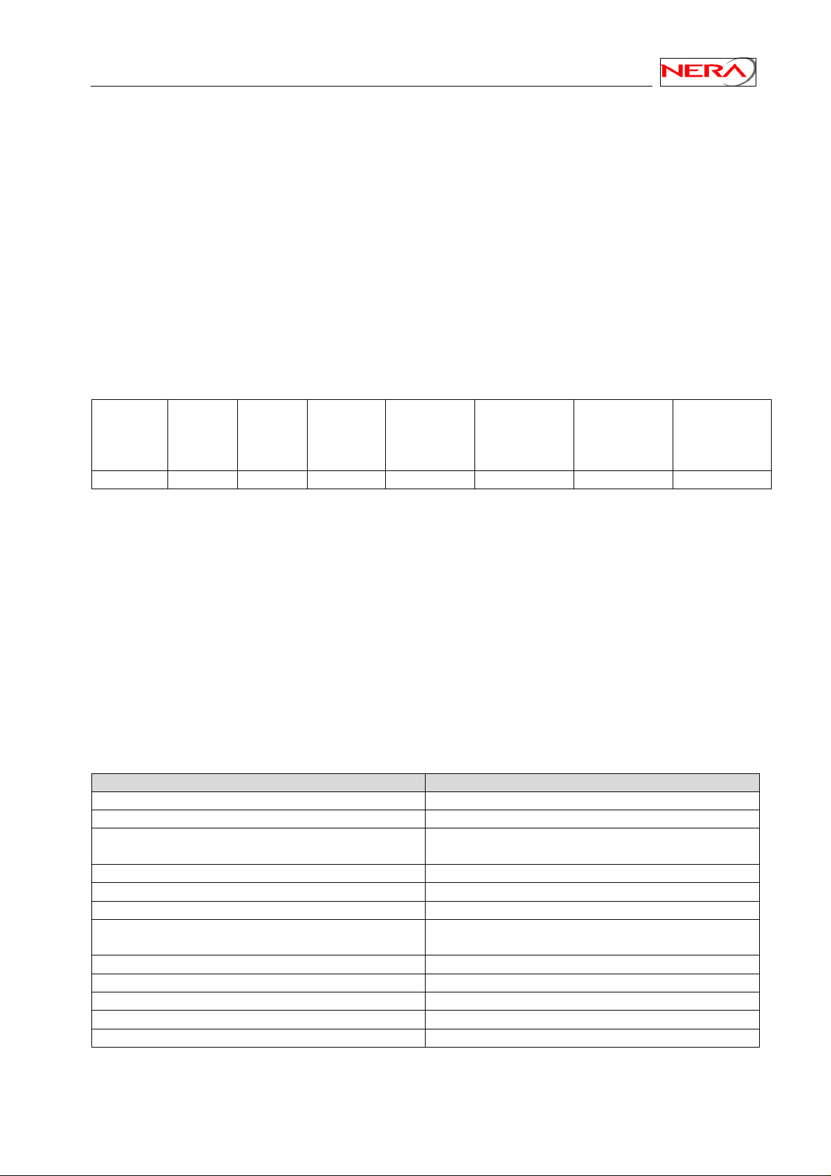
In order to be able to decide which QoS group an IP packet destined for the return link belongs to, the
SatLink terminal has a table called the QoS classification table which can store up to 15 different masks
that the IP packets will be matched against to decide which QoS group it belongs to.
The following parameters in the IP header can be used for doing the QoS classification:
• IP source address
• IP destination address
• DSCP / TOS
• Protocol type
• TCP/UDP source port number
• TCP/UDP destination port number
The format of the QoS classification table is:
Index QoS
Group
Index
Dest. IP
Address
Mask
Source IP
Address
Mask
DSCP
Range
(Start-Stop
values)
Protocol
Type
(up to 3
values)
TCP/UDP
Source Port
Range (StartStop values)
TCP/UDP
Dest. Port
Range (StartStop values)
1-15 0 or 1 0-63 0-255 0-65535 0-65535
The index parameter is used to uniquely identify an entry in the QoS classification table, and to decide the
order in which the QoS classification table is searched. When an IP packet destined to the return link shall
be QoS classified, the QoS classification table is searched from index 1 to index 15. If a match is found
for an entry in the QoS classification table, the search is stopped and the IP packet is thereafter handled
with the QoS Group for this entry in the QoS classification table. If a match is not found for an IP packet
it will be treated as best effort traffic. The available QoS groups are:
0. Best effort
1. VoIP and other real-time continuous rate traffic
The CLI command to be used to configure the QoS Classification table is
ip qos mask <index> <qos group index> <list of tags>. This command has a variable
length where one ore more tags with different tag parameters can be set. The tags are the different IP
header parameters that can be used for QoS classification:
tag and tags parameters for CLI command Function
+src <ipaddr> <mask>
-src
+dst <ipaddr> <mask>
Define or modify IP source address and netmask
Delete IP source address and netmask
Define or modify IP destination address and
netmask
-dst
+dscp <min> <max>
-dscp
+prot <n> <p1> … <pn>
Delete IP destination address and netmask
Define or modify DSCP range
delete DSCP range
Define protocol value [0,255]. Up to 3 protocol
values can be defined (n can be 1, 2, or 3).
-prot
+sport <min> <max>
-sport
+dport <min> <max>
-dport
Delete protocol values
Define TCP/UDP source port number range
Delete TCP/UDP source port number range
Define TCP/UDP destination port number range
Delete TCP/UDP destination port number range
To view the current QoS configuration, use the CLI command ip qos show.
41
Page 42

Nera SatLink Terminal User Guide
Examples:
To add an entry in the QoS classification table matching protocol type 7 and assign this to the VoIP QoS
Group
ip qos mask 3 1 +prot 1 7
To add one more classification criteria for the same entry, e.g. destination address:
ip qos mask 3 1 +dst 10.10.22.0 255.255.255.0
To delete one classification criteria from en entry from the QoS classification table:
ip qos mask 3 1 –prot
To delete the whole entry from the QoS classification table:
ip qos mask 3 –all
To add a new entry for classifying VoIP traffic:
ip qos mask 1 1 +src 10.10.10.1 255.255.255.255 +dscp 10 15
To view the current QoS configuration
ip qos show
42
Page 43

Nera SatLink Terminal User Guide
9. Return link capacity
The Nera SatLink terminal supports the following DVB-RCS mechanisms for requesting capacity on the
return link:
• Volume based (VBDC)
• Rate based (RBDC)
Please refer to [11] for a detailed description of the return link capacity types.
The capacity request mechanism to use is decided by the QoS groups. In the current software version the
following 2 supported QoS groups are:
0. Best effort
1. VoIP / Real-time
Both these QoS groups use the RBDC capacity request method for requesting return link capacity from
the NCC at the DVB-RCS gateway. The capacity that the NCC has allocated to the Nera SatLink
Terminal on the return link can be viewed using the CLI command dvb tx show -capacity
Example:
# dvb tx show -capacity
Capacity parameters per channel:
-------------------------------
Channel CRA MaxRBDC MaxVBDC Allocated
[ID] [kbps] [kbps] [kbps] [kbps]
0 14 200 0 20
Requested capacity per QoS class:
--------------------------------Queue Chn MaxRBDC MaxVBDC RateReq VolumeReq
[ID] [ID] [kbps] [kbps] [kbps] [pkts]
4 0 100 0 0 0
In the example above the NCC has assigned a continuous return link capacity (CRA) of 14 kbps and an
additional variable capacity limit (MaxRBDC) of 200 kbps to the Nera SatLink Terminal. The maximum
capacity the Nera SatLink Terminal can get on the return link is therefore 214 kbps. In the example above
the current capacity is 20 kbps.
• CRA: Allocated CRA capacity (DVB-RCS Constant Rate Assignment capacity).
CRA capacity may be assigned from the DVB-RCS gateway when logged on the
network, depending on the subscription type chosen from the DVB-RCS service
provider.
• MaxRBDC: Maximum possible RBDC capacity that can be allocated on top of the allocated
CRA capacity. The maximum RBDC capacity is set from the DVB-RCS
gateway, depending on the subscription type chosen from the DVB-RCS service
provider.
• MaxVBDC: Maximum possible VBDC capacity that can be allocated on top of possibly other
allocated CRA and RBDC capacity. The maximum VBDC capacity is set from
the DVB-RCS gateway, depending on the subscription type chosen from the
DVB-RCS service provider.
• Allocated: Current allocated total capacity (all capacity types)
43
Page 44

Nera SatLink Terminal User Guide
10. Traffic Initiated Logon
The SatLink Terminal can be configured to logon automatically to the DVB-RCS gateway only when it
has traffic to send, and logoff again when it has had no traffic to send for a configurable timeout period.
This mode is useful for terminal installations where low power consumption is important (when the
terminal is powered by solar power and batteries) and in systems where it is to reduce the signalling
bandwidth on the return channel (not use dedicated SYNC slots when the terminal has no traffic to send).
The power saving mode requires the use of the Nera SatLink 3000 transmitter (BUC). The power
consumption will then be reduced from typically 45W to approximately 22W when the terminal is logged
off.
The Nera SatLink Terminal can be configured to use traffic initiated logon by typing the CLI command
dvb tx autostart traffic <timeout> where <timeout> is the timeout in minutes the terminal
will wait before logging off when it has no traffic to send.
Example:
dvb tx autostart traffic 5
will configure the SatLink Terminal to use traffic initiated logon and automatically log off the network
after not having any traffic to send for 5 minutes.
Verify the configuration of the transmitter mode and the timeout for traffic initiated logon by typing the
CLI command dvb tx show.
44
Page 45

Nera SatLink Terminal User Guide
11. Updating the Nera SatLink Terminal SW
The flash in the Nera SatLink Terminal can store two SW images, both the currently used SW and a
backup version in case download of a new SW version fails.
11.1 Automatic software update
The Nera SatLink Terminal may be configured for receiving software updates from the DVB-RCS
gateway automatically. Whenever the software upgrade application at the DVB-RCS gateway transmits a
new software image on the configured PID, multicast IP address, and UDP port, the software upgrade
routine in the Nera SatLink Terminal will start receiving the software image if it detects that the new
software image has a newer revision than the current software. When the software download is completed
successfully, the Nera SatLink Terminal will restart automatically in order to activate the new software
version.
To automatically receive software upgrades, the Nera SatLink Terminal must be configured with the PID,
the multicast IP address, and the UDP port allocated by the system operator for multicast software
upgrade, with software upgrade via multicast enabled, and with the terminal receiver locked on the
forward link. Issue the CLI command sw show to examine the automatic software upgrade
configuration:
# sw show
SW versions
-------------------------------Current : 7.0.0.14
Backup : 1.9.1.38
Manual SW upgrade settings
-------------------------------TFTP server IP addr : 10.10.1.8
File name : dvb-rcst.tgz
Automatic SW upgrade settings
-------------------------------Activated : No
PID : 511
IP address : 224.0.1.59
Port No. : 2001
#
Users with privilege level 1 may activate and deactivate the automatic software upgrade routine, and
change the PID, IP address, and UDP port number where the software is received by using the CLI
command sw mcast.
Example:
# sw mcast 1 511 224.0.1.59 2001
#
will enable automatic reception of software upgrades on PID 511, IP address 224.0.1.59 and UDP port
number 2001.
45
Page 46

Nera SatLink Terminal User Guide
11.2 Manual software update
User with privilege level 1 or 2 may use the CLI command sw upgrade to download a new software
image from the default TFTP server. After successful download of a new software image, the previous
software version will be stored as a backup version before enabling the new software.
Below is described in detail how to upgrade the Nera SatLink Terminal software:
1. Verify the default settings for the manual software upgrade with the CLI command sw show
2. If necessary, update the default settings for the manual software update by using the CLI command
sw upgrade –default <upgraded-SW-filename> <tftp-ip-address>
3. Verify the settings with the CLI command sw show
4. Execute the SW upgrade by typing sw upgrade, then restart the Nera SatLink Terminal
Example:
# sw show
SW versions
-------------------------------Boot : 1.8.0.2 or older
Current : 7.0.0.14
Backup : 1.9.1.38
Manual SW upgrade settings
-------------------------------TFTP server IP addr : 10.10.1.1
File name : dvb-rcst.tgz
Automatic SW upgrade settings
-------------------------------Activated : Yes
PID : 511
IP address : 224.0.1.59
Port No. : 2001
Licenses for SW options
-------------------------------DHCP srv : License available
NAT : License available
GRE : License available
#
# sw upgrade -default dvb-rcst.tgz 10.10.10.8
# sw upgrade
Software download in progress, please wait...................................
...........................................................................
File Transfer complete
Software download completed - Preparing to restart the terminal
Configuration Saved
RESTARTING TERMINAL
46
Page 47

Nera SatLink Terminal User Guide
11.3 Restoring the backup software
If one for some reason must restore the old software, then the following steps have to be executed. Please
note that the current SW will be deleted when restoring the backup SW.
1. Restore the previous SW with the command sw restore, then restart the terminal
Example:
# sw restore
Restoring backup SW - version Product ID 101224, Revision 1.9.1.38
Current SW version Product ID 101224, Revision 7.0.0.14 will be deleted
Do you want to continue (Y/N)?y
Backup SW restored, Saving Configuration - Please wait up to 20 seconds
Configuration Saved
Do you want to restart now to start using the restored SW ?(Y/N)?y
Restarting Terminal. Connection will be closed
RESTARTING TERMINAL
47
Page 48

Nera SatLink Terminal User Guide
12. Software options
The Nera SatLink terminal supports the following features available as options:
• Network Address Port Translation (NAPT)
• GRE Tunnelling
To show the list of options for which licenses are installed on the Nera SatLink Terminal, use the CLI
command sw show
Example:
# sw show
SW versions
-------------------------------Boot : 1.8.0.2 or older
Current : 7.0.0.14
Backup :
Manual SW upgrade settings
-------------------------------TFTP server IP addr : 10.10.1.1
File name : dvb-rcst.tgz
Automatic SW upgrade settings
-------------------------------Activated : No
PID : 511
IP address : 224.0.1.59
Port No. : 2001
Licenses for SW options
-------------------------------NAT : License available
GRE : License available
To enable a software license, a license key has to be entered by using the CLI command sw license.
Please contact the system operator or Nera if access to a new software option is wanted.
12.1 Network Address Port Translation (NAPT)
Network Address Translation is a mechanism to provide transparent IP-level access to the Internet from a
local site with a private address range without requiring all the hosts on the site to have globally valid IP
addresses. It requires only one globally valid IP address, which is then configured for the DVB (Satellite)
Interface of the Nera SatLink Terminal. NAT translates addresses in incoming and outgoing IP packets by
replacing the source address in each outgoing IP packet with the globally valid IP address, and replacing
the destination address in each incoming IP packet with the private address of the destination host on the
local site. Network Address Port Translation (NAPT), sometimes called Port-Mapped NAT, is a popular
variant of NAT providing concurrency by translating TCP or UDP protocol port numbers as well as
addresses14. The globally valid IP address used for address translation when NAPT is enabled is the Nera
SatLink Terminal’s own DVB interface IP address.
14
Translation of outbound TCP/UDP fragmented datagrams will fail with NAT enabled. The reason is
that only the first fragment contains the TCP/UDP header that would be necessary to associate the packet
to a session for translation purposes. Subsequent fragments do not contain TCP/UDP port information,
but simply carry the same fragmentation identifier specified in the first fragment. Consequently the
sessions will be corrupted. Whether NAT drops or forwards also an ICMP fragmented packets depends
on a number of things, such as the order in which the NAT router receives the ICMP fragments, and the
48
Page 49

Nera SatLink Terminal User Guide
To enable Network Address Port Translation in the Nera SatLink Terminal, use the CLI command
ip nat enable
Example:
# ip nat enable
To show the status of the Network Address Port Translation in the Nera SatLink Terminal, use the CLI
command ip nat show
Example
# ip nat show
NAT:
---Network Address Port Translation (NAPT): Enabled
12.2 Generic Routing Encapsulation (GRE) and IP Tunnelling
The Nera SatLink Terminal supports configuration of one IP tunnel from its DVB interface with Generic
Routing Encapsulation (GRE) as specified in RFC 2784. Only the tunnel termination interface IP address,
tunnel logical destination IP address and subnet mask need to be specified since the tunnel will always be
set up from the DVB interface.
Example:
#ip gre add 192.168.1.0 255.255.255.0 10.20.1.1
Will set up a tunnel on the DVB interface to the IP address 10.20.1.1 for the subnet
192.168.1.0/255.255.255.0.
To verify that a GRE tunnel and a GRE interface have been created, use the CLI command ip gre
show.
Example:
# ip gre show
GRE Tunnel Interfaces:
---------------------If Tunnel Local Address Tunnel Remote Address
4 192.168.255.2 10.20.1.1
Interface number 4 has been allocated for the GRE interface. Use the CLI command ip show to verify that
a new IP interface has been created, and that 2 new entries have been added to the IP routing table. The
first entry in order to route traffic with destination address equal to the tunnel remote address to the DVB
interface. The second entry to route traffic with destination address belonging to the tunnel remote local
subnet to the GRE interface.
# ip show
Interfaces
If IPAddress SubnetMask BroadCastAddr MTU Alias AdminStatus
1 10.10.20.115 255.255.255.248 10.10.20.119 1500 eth0 1
2 N/A N/A N/A 4074 air0 1
3 192.168.255.2 255.255.255.0 192.168.255.255 4074 dvb0 1
4 N/A N/A 255.255.255.255 4074 gre0 1
state of the translation table at that time. Under certain conditions, NAT translates the ICMP fragments
differently, making it impossible for the destination device to reassemble the packet.
49
Page 50

Nera SatLink Terminal User Guide
Interface Statistics
------------- Input ----------------- ------------- Output ---------------If UCast NUCast Disc Octets UCast NUCast Disc Octets
1 14 98 43 13737 18 29 0 4984
2 0 0 0 0 0 0 0 0
3 0 0 0 0 0 0 0 0
4 0 0 0 0 0 0 0 0
Routing Table
DestMask RouteMask NextHop If
0.0.0.0 0.0.0.0 0.0.0.0 3
10.10.20.112 255.255.255.248 0.0.0.0 1
10.20.1.1 255.255.255.255 0.0.0.0 3
192.168.1.0 255.255.255.0 0.0.0.0 4
192.168.255.0 255.255.255.0 0.0.0.0 3
To route unicast/multicast addresses specifically to the GRE interface, use the CLI command ip
addroute
Example
# ip addroute 225.0.0.2 255.255.255.255 4
Will forward multicast datagrams with IP address 225.0.0.2 from the Nera SatLink Terminal LAN
interface to the GRE interface (note that forwarding of multicast IP traffic from DVB interface to GRE
interface is not supported in the current release). As shown by the CLI command ip show -mcast
# ip show -mcast
IP Multicast Routing Table
RouteAddress AddressMask IfIndex
225.0.0.2 255.255.255.255 4
239.255.255.250 255.255.255.255 1
50
Page 51

Nera SatLink Terminal User Guide
13. Setting up routing of multicast traffic from the SatLink
Terminal LAN to the gateway
The Nera SatLink Terminal can be configured to route multicast traffic from the LAN to the return
channel (to the gateway). User privilege level 1 or 2 is required for configuring the multicast routing.
To set up static routing of a multicast group from the LAN to the satellite interface, use the CLI command
ip addroute <IP group address> <subnet mask> <ifnum>. Where IP group address is
the IP multicast address that shall be routed from the Ethernet LAN to the gateway, subnet mask is the
netmask for this routing entry, and ifnum is the interface number (always set this to 3 = Satellite
Interface).
Example:
# ip addroute 224.0.2.2 255.255.255.255 3
#
The command in the example will set up a route for the multicast group with the IP address 224.0.2.2 to
the satellite interface (to the gateway).
To view the defined multicast routes use the CLI command ip show -mcast.
Example:
# ip show -mcast
IP Multicast Routing Table
RouteAddress AddressMask IfIndex
224.0.0.2 255.255.255.255 1
224.0.2.2 255.255.255.255 3
#
Please note that subnetwork internal multicast groups on the LAN will show up in the multicast route
table. LAN internal multicast traffic is e.g. generated by Windows (Network neighbourhood, etc.). Such
traffic will have the IfIndex set to 1.
To delete multicast routes use the CLI command
ip delroute <IP group address> <subnet mask> <ifnum>.
Example:
# ip delroute 224.0.2.2 255.255.255.255 3
will delete the static route of the multicast group with the IP address 224.0.2.2 from the Ethernet LAN to
the satellite interface (gateway).
The multicast IP address to be routed onto the return link can be associated with a different PID to be
used on the return link. Enter the CLI command
dvb addroute <destaddr> <netmask> 0 MPG 0 <pid> to define a return link route for the
specified multicast IP-address to a specific return link PID. For multicast IP addresses the MAC address
used on the return link will be calculated according to RFC 1112.
Example:
# dvb addroute 224.0.2.2 255.255.255.255 0 MPG 0 511
#
51
Page 52

Nera SatLink Terminal User Guide
will configure the Nera SatLink terminal to route the multicast stream 224.0.0.2 with RFC1112
destination MAC address onto PID 511.
To display the configured return link IP address to PID mappings, enter the CLI command
dvb showroute.
Example:
# dvb showroute
Subnet NetMask Q MAC Address CH PID VPI VCI SID T
225.0.2.2 255.255.255.255 0 00:00:00:00:00:00 0 511 0 0 0
#
To delete a return link IP address to channel ID / PID map entry, use the CLI command
dvb delroute <destaddr> <netmask>.
Enter the CLI command save config to save the return link multicast configuration,
52
Page 53

Nera SatLink Terminal User Guide
14. Definitions, Acronyms and Abbreviations
BER Bit Error Rate
BUC Block Up-Converter
CLI Command Line Interface
CRA Continuous Rate Assignment
CSC Common Signalling Channel
CW Continuous Wave
DiSEqC Digital Satellite Equipment Control
DNS Domain Name Service
DVB Digital Video Broadcasting
DHCP Dynamic Host Configuration Protocol
DSCP DiffServ Code Point
EIRP Equivalent Isotropic Radiated Power
FCA Free Capacity Assignment
GW GateWay
GRE Generic Routing Encapsulation
HPC High Power Converter
HW HardWare
ID IDentifier
IDU InDoor Unit
IETF Internet Engineering Task Force
IF Intermediate Frequency
IP Internet Protocol
ICMP Internet Control Message Protocol
GPS Global Positioning System
LAN Local Area Network
LNB Low Noise Block
MAC Medium Access Control
MIB Management Information Base
NAT Network Address Translation
NAPT Network Address Port Translation
NCC Network Control Centre
ODU OutDoor Unit
OMT Ortho-Mode Transducer
OS Operating System
PAT Program Association Table
PID Packet Identifier
QoS Quality of Service
RBDC Rate Based Dynamic Capacity
RCS Return Channel on Satellite
RCST RCS Terminal
RF Radio Frequency
RFC Request For Comments
RMT RCS Map Table
RRM Radio Resource Management
RX Receiver
SNMP Simple Network Management Protocol
SW SoftWare
TCP Transport Control Protocol
TDT Time and Date Table
TFTP Trivial File Transfer Protocol
TOS Type Of Service
TX Transmitter
53
Page 54

Nera SatLink Terminal User Guide
UDP User Datagram Protocol
VBDC Volume-Based Dynamic Capacity
XPD Cross-Polar Discrimination
15. References
[1] Channel Master Instruction and Assembly manual. Type 960 .96m Rx-Tx Antenna System with
Factory Assembled AZ/EL Cap, Nera document No. 101497.
[2] Channel Master Instruction and Assembly manual. Type 123 1.2m Rx-Tx Antenna System with
Factory Assembled AZ/EL Cap, Nera document No. 101705.
[3] Channel Master Instruction and Assembly manual, Type 184 1.8m Offset Tx/Rx Antenna System, Nera
document No. 104218.
[4] Assembly User’s Manual and Operating Instructions for Visiosat Tx/Rx 75cm Offset Antenna,
Nera document No. 104215.
[5] User’s Assembly Manual and Operating Instructions for Visiosat 90 Dual Reflector Transmit /
Receive Antenna, Nera document No. 103174.
[6] Nera SatLink 1900 & 1901. Management via SNMP, Nera document No. 103951.
[7] Digital Video Broadcasting, The International Standard for Digital Television, by Ulrich Reimers
et.al., Berlin, Springer Verlag, 2001, 295 pages hardcover, ISBN 3-540-60946-6.
[8] Digital Video Broadcasting, by Ulrich Reimers, Berlin, Springer Verlag, 2002, 350 pages hardcover,
ISBN 3-540-3545-X.
[9] Digital Video Broadcasting website at www.dvb.org
[10] European Telecommunications Standards Institute website at www.etsi.org
[11] Digital Video Broadcasting (DVB); Interaction channel for satellite distribution systems,
ETSI EN 301 790, V1.3.1
54
Page 55
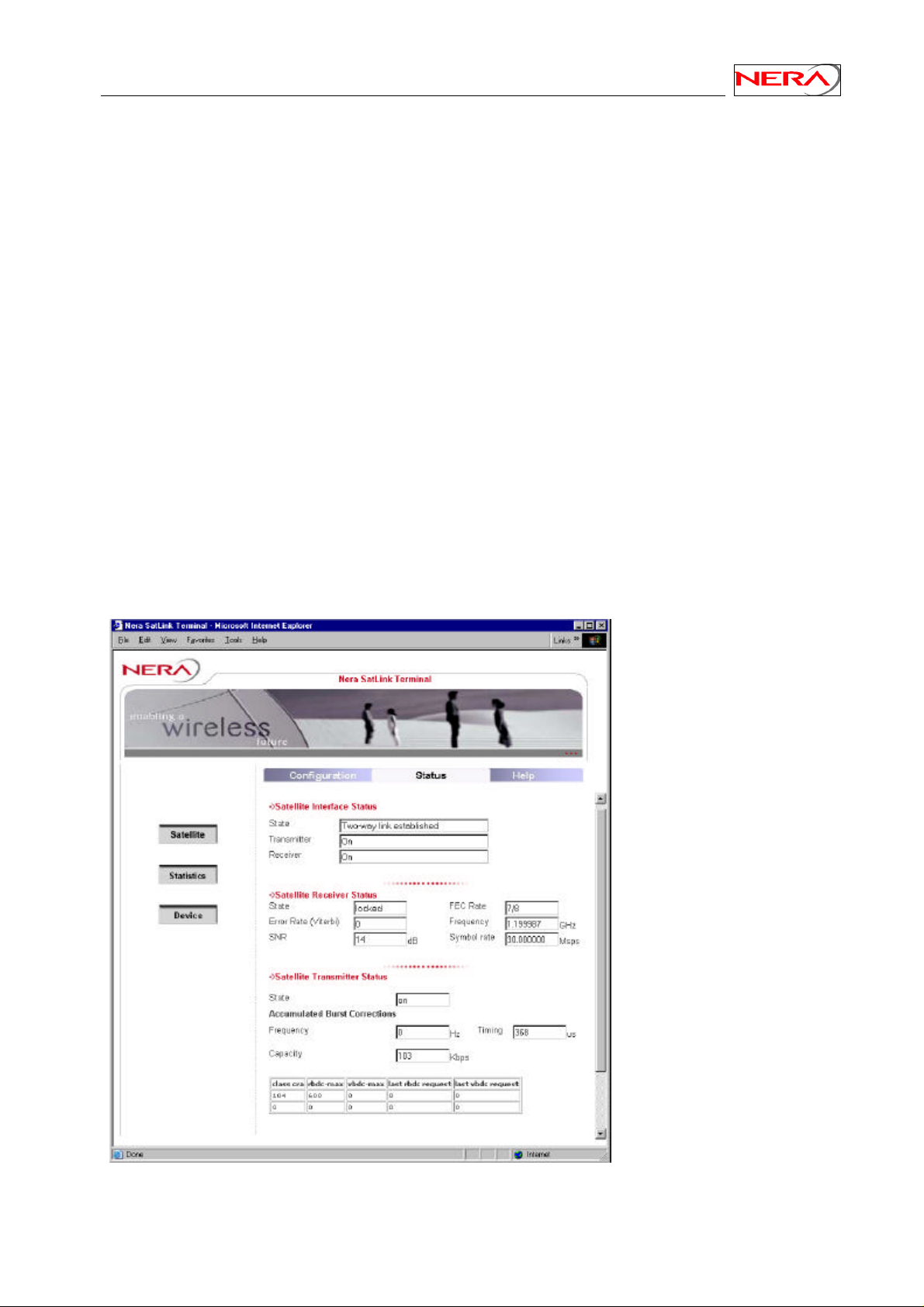
Nera SatLink Terminal User Guide
Appendix A. Using the Web Interface
The Web interface supports managing the most common configuration parameters and viewing the status
of the Nera SatLink Terminal. The Web-browsers currently supported are Microsoft Internet Explorer 6.0
and Opera 7.2x, but other browsers and versions may work as well. Advanced functions like
enabling/disabling NAT, configuring GRE tunnels, configuring the DHCP server, downloading software
updates manually, configuring automatic software updates, configuring system information, adding users
and changing password, configuring SNMP access, and adding manual IP routes, are only available from
the CLI via Telnet or the RS-232 port. If experiencing any problems using the Web interface for
management of the Nera SatLink Terminal, please use the CLI via Telnet or RS-232 as a work-around for
the problem..
Please note that the Web-server in the Nera SatLink Terminal is given less priority than the processes that
take care of the data transfer to and from the Satellite interface. This may occasionally result is slow
response times for the Web pages.
A.1 Status of the Nera SatLink terminal
A.1.1 Satellite interface status
The status of the satellite interface can be seen by choosing the "Status" page. The page consists of three
parts: The status for the satellite interface as well as more detailed status for both the satellite receiver and
transmitter.
Figure 12: Status of Satellite Interface
55
Page 56
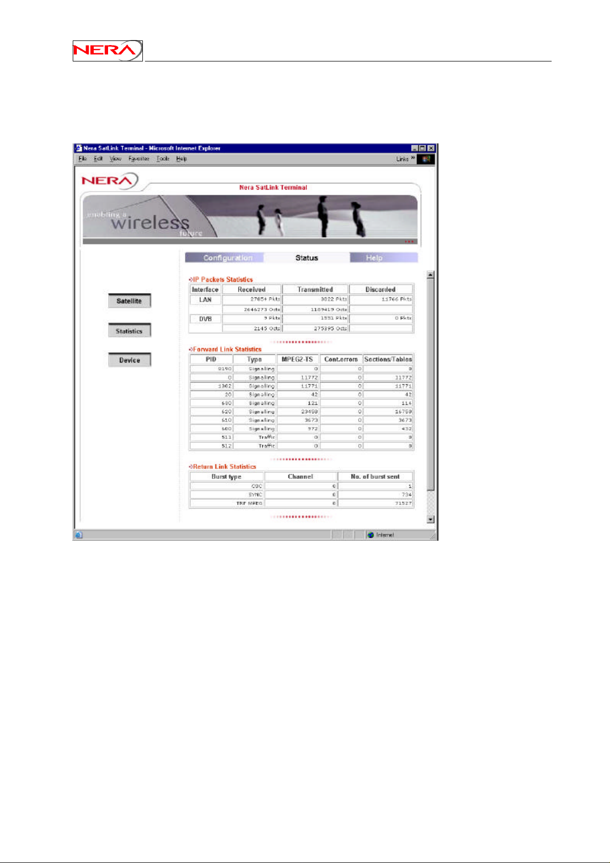
Nera SatLink Terminal User Guide
A.1.2 Traffic statistics
Traffic statistics can be seen by choosing the "Status" page, and then selecting the "Statistics" button. The
page consists of three tables: IP packet statistics, satellite forward link statistics (receive), and satellite
return link statistics (transmit).
Figure 13: Statistics page
56
Page 57
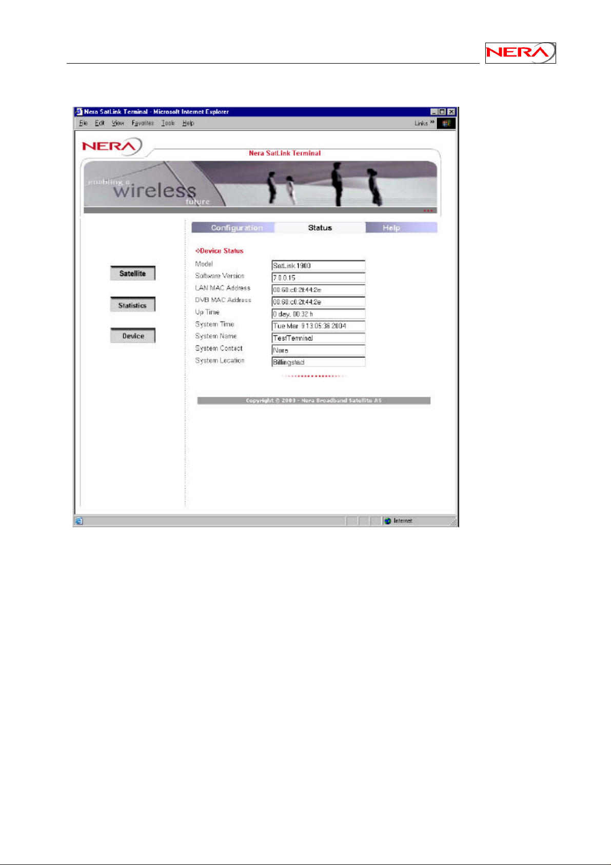
Nera SatLink Terminal User Guide
A.1.3 Device information
Figure 14: Device status
57
Page 58

Nera SatLink Terminal User Guide
A.2 Configuration of the satellite interface
The most common configuration parameters of the satellite interface can be set from the Web interface:
• Autostart on/off for the transmitter
• Population ID
• EIRP. Need only be set when using the Nera SatLink 3000 transmitter (BUC).
• IDU output power. Need only be set when using the following transmitters (BUCs):
• Invacom TUL-204
• Nera SatLink 3000 (Revision 3.0 or older)
• Norsat 1010/1020XRT
• ODU Transmitter type. The following transmitters (BUCs) can be selected from the Web-interface:
• Invacom TUL-204
• Nera SatLink 3000 (Revision 5.0 and newer)
• Norsat 1010/1020XRT
• Antenna Type. When the terminal is configured with the SatLink 3000 transmitter (BUC), the correct
antenna must be configured to allow the Nera SatLink Terminal to compute the correct EIRP. The
following antennas are supported:
• Channel Master Type 960 - 96cm
• Channel Master Type 123 - 1.20m
• Channel Master Type 184 - 1.80m
• Raven G90 - 80x89cm
• Visiosat Tx/Rx 90cm Gregorian Offset Antenna
• Visiosat Tx/Rx 75cm Offset Antenna
• Autostart on/off for the receiver
• Forward link frequency
• Forward link symbolrate
• LNB Type. The following LNBs are supported:
• Invacom SPV1-SM
• Universal LNBs (only for receive only antennas)
• Terminal position
•
Please note that these parameters should only be changed to values specified by the system operator,
otherwise the connection to the DVB-RCS Gateway will most likely be lost.
58
Page 59
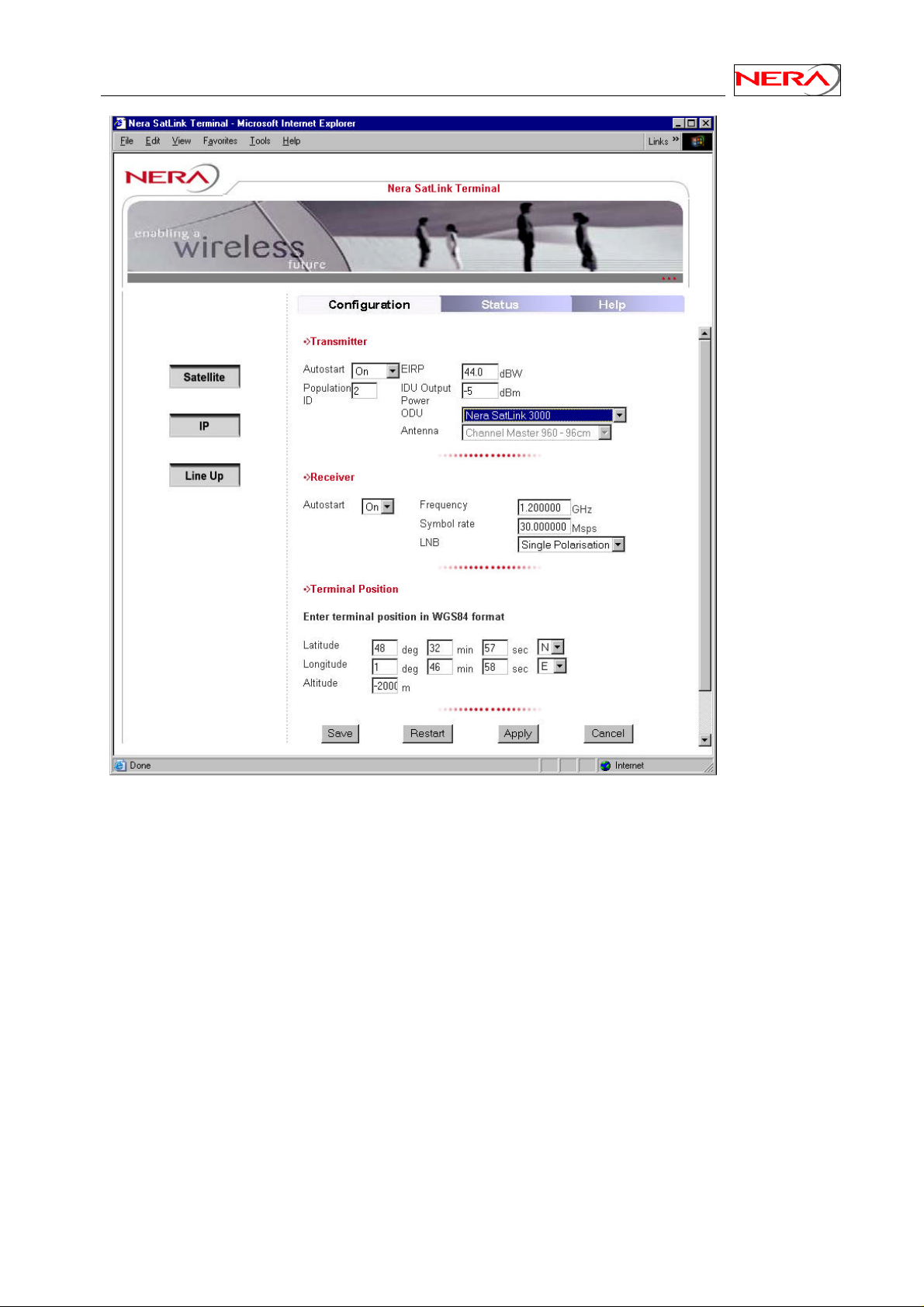
Nera SatLink Terminal User Guide
Figure 15: Satellite Interface Configuration
59
Page 60
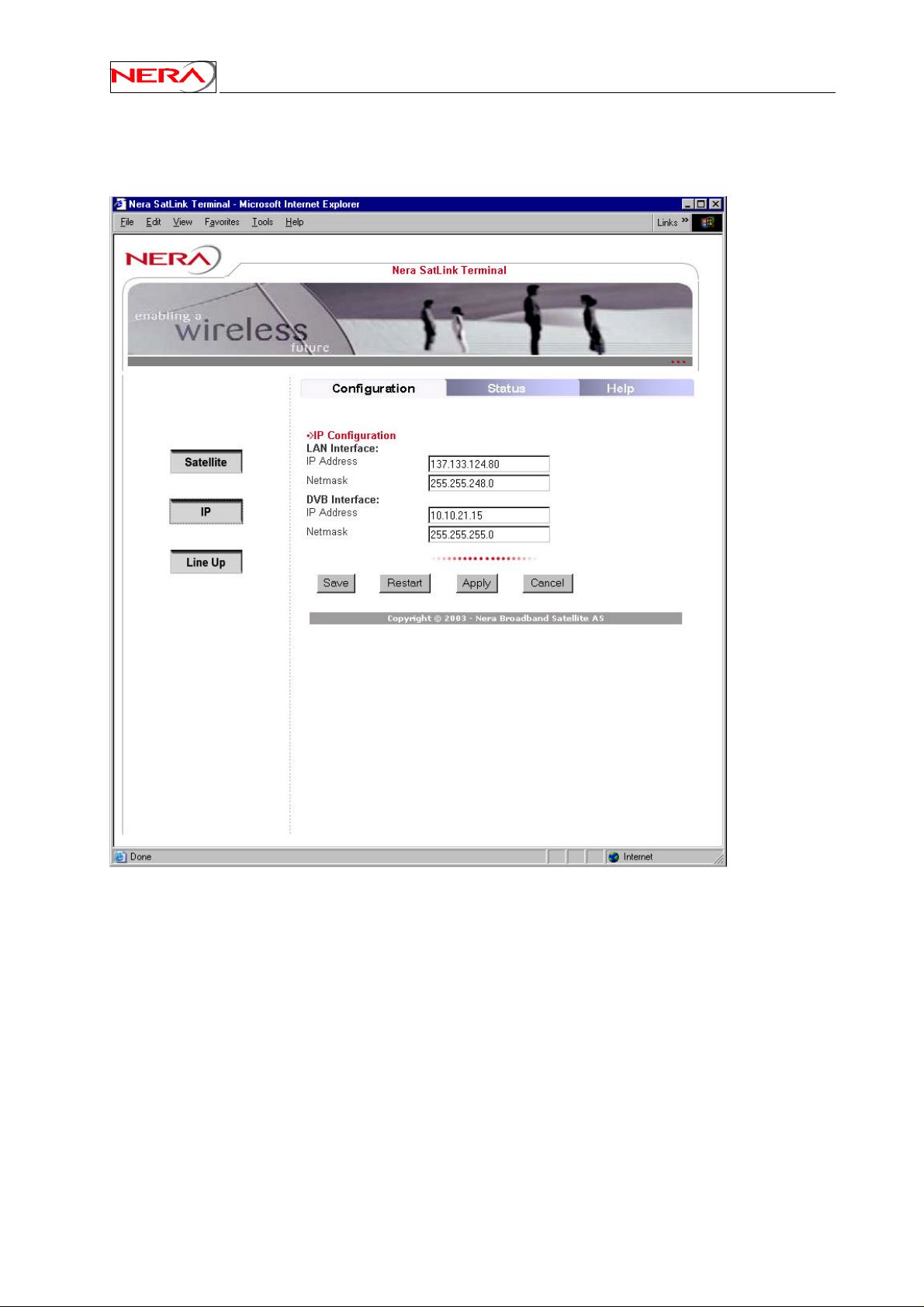
Nera SatLink Terminal User Guide
A.3 IP address configuration
The IP addresses of the Nera SatLink terminal can be set from the Web-interface.
Figure 16: IP address configuration
Note: Please note that after saving the new IP address the IDU needs to be restarted for the changes to
take place. The browser window may look incomplete during this save and needs to be closed and opened
again typing in the new address after restarting the IDU.
60
Page 61

Nera SatLink Terminal User Guide
A.4 Terminal line-up
A continuous wave (CW) can during line-up be transmitted for calibrating the IDU output power level,
and for aiding the fine adjustment of the antenna pointing and polarisation. After the correct IDU output
power level has been found (automatically when using the Nera SatLink 3000, manually when using
other transmitters (BUCs)), the pointing and polarisation of the antenna should be fine adjusted based on
measurements from the system operator on the transmitted CW.
The Nera SatLink 3000 has an integrated power detector, simplifying the line-up since the IDU output
power can be automatically calibrated by the Nera SatLink Terminal to transmit the configured EIRP.
When using other transmitters, the IDU output power must manually be adjusted during line-up according
to feedback from the control centre. Please then be aware of the possibility for setting the IDU output
level too high in order to compensate for the antenna pointing not being accurate enough.
A.4.1 Nera SatLink 3000
In order to do a line-up of the terminal, ensure that the correct frequency for transmitting a continuous
wave (CW) and the wanted EIRP is configured, and when permission to start CW transmission is granted
from the control centre, push the button "Start Calibration". The correct output level from the IDU will
then be found based on output power level measurements from the Nera SatLink 3000. The IDU will use
the power level found during the calibration as the initial power level for the logon burst each time it tries
to logon.
After the automatic power level calibration is completed, the CW is left on for 20 minutes such that fine
adjustments of antenna pointing and polarisation can be completed based on feedback from the control
centre. By pushing the button "CW on", CW transmission can be started without doing the automatic
power calibration.
A.4.2 Norsat 1010/1020XRT and Invacom TUL-204
In order to do a line-up of the terminal, ensure that the correct frequency for transmitting a continuous
wave (CW) is configured, and that the IDU output power level is set to a low value (-30 dBm is
recommended as the initial value). Then call the control centre and push the button "CW on" to start
transmitting the CW when permission to transmit is granted. Adjust the IDU output power in small steps
(never more than 5 dB) based on feedback from the control centre.
After the initial IDU output power level has been found, the pointing and polarisation of the antenna
should be fine adjusted based on feedback from the control centre. When the antenna has be fine adjusted,
the received signal level at the control centre for the CW should again be verified, and the IDU output
power level adjusted if necessary. Please remember to save the configuration (the Save button on the
Satellite configuration page) after completing the line-up.
61
Page 62
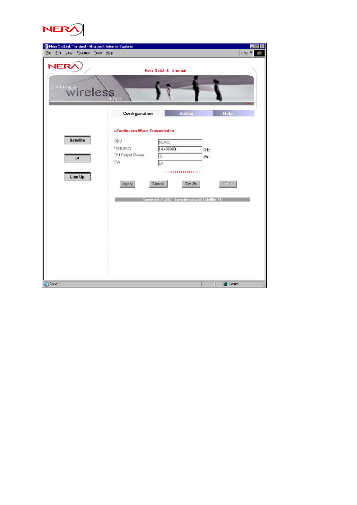
Nera SatLink Terminal User Guide
Figure 17: Terminal line-up
62
Page 63
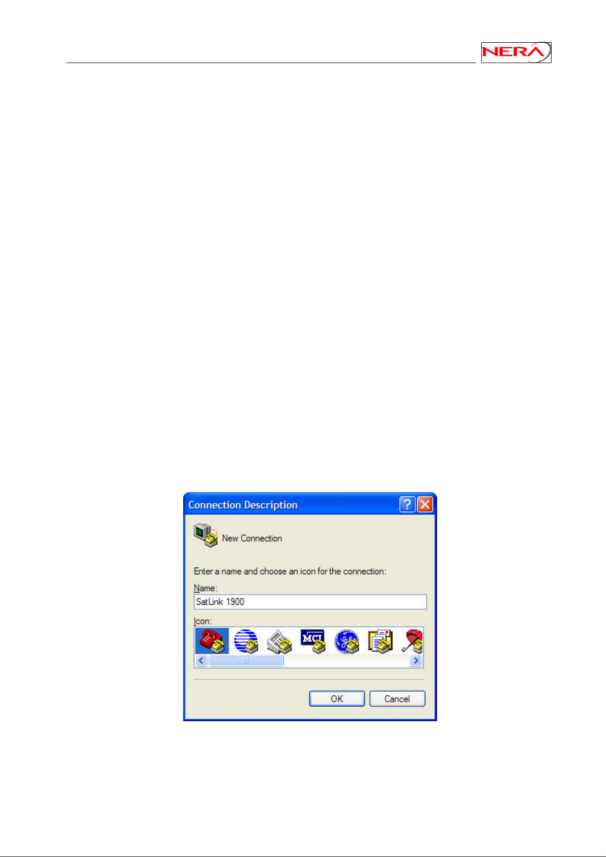
Nera SatLink Terminal User Guide
Appendix B. Accessing the Command Line Interface via
RS-232
In some special situations the Command Line Interface via Telnet may not be accessible or will not
output the required amount of debug information. Typical examples of such situations are:
• The Nera SatLink Terminal is configured with an Ethernet IP address not known to the user
• One needs to enter the boot-loader
• Detailed debugging
The Command Line Interface may then be accessed from a local PC connected to the Nera SatLink
Terminal’s RS-232 interface via a serial cable. HyperTerminal or any compatible terminal emulation
program is used to access the CLI interface via RS-232.
B.1 Cable connection
To get access to the command-line interface (CLI) via the RS-232 connection, a serial cable is connected
from the SatLink Terminal directly to a COM port on a PC:
• Plug the 9-pin connector (DB09) (male) into the rear panel of the SatLink Terminal.
• Plug the 9-pin connector (DB09) (female) into a COM port on the PC.
B.2 PC configuration of HyperTerminal to access the CLI via RS-232
In Windows, click the Start button and select All Programs > Accessories > Communications >
HyperTerminal. HyperTerminal will then start and the Connection Description dialogue box, shown in
Figure 18, will appear. The screen shots are from Windows XP Professional; other versions of Windows
may display differently.
Figure 18: Hyper Terminal New Connection dialogue box
Enter a name and select an icon for the Connection, and click OK. The Connect To dialogue box, shown
in Figure 19, will appear.
63
Page 64
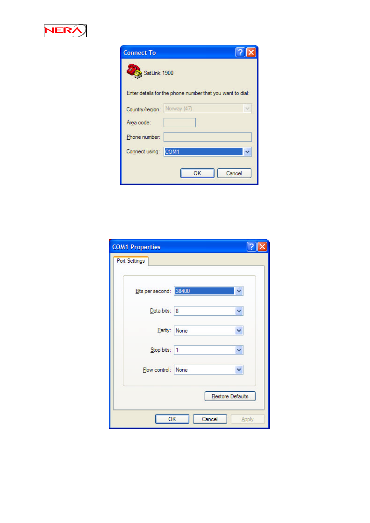
Nera SatLink Terminal User Guide
Figure 19: Hyper Terminal Connect To dialogue box
Select the COM port where the serial cable attached to the Nera SatLink Terminal is connected, and click
OK. The COM port Properties property sheet will appear, as shown in Figure 20.
64
Figure 20: Hyper Terminal COM1 Properties property sheet
Page 65

Nera SatLink Terminal User Guide
Use the pull-down lists to enter:
• Bits per second: 38400
• Data bits: 8
• Parity: None
• Stop bits: 1
• Flow control: none
Click Apply to accept the properties. The property sheet will close and communication with the
SatLink Terminal may begin.
Note that it may be necessary to press the enter key to display the login prompt.
When closing the session and exiting HyperTerminal, allow the program to save the session, which will
place an icon and session name into the HyperTerminal directory on the Start menu, allowing for future
quick connections.
65
Page 66

Nera SatLink Terminal User Guide
Appendix C. TFTP server
TFTPD32 is a freeware TFTP server for Windows 9x/NT/XP PCs (but seems to work on Windows 2000
as well), which is small, and easy to install and use. Use the copy on the CD included with the
SatLink Terminal, or use the link below and download the software.
http://tftpd32.jounin.net/
Short installation description:
1. Copy the TFTP server files to a PC located at either the gateway or a local LAN
2. Start the program tftpd32.exe
3. Select correct server interface if using a PC with more than one Ethernet card.
4. Select correct base directory (directory where the files to be downloaded are stored, and where
uploaded files will be stored)
5. You are up and running with a TFTP server
6. The TFTP server can now be accessed from the Nera SatLink Terminal by using the CLI
commands upload and dload.
TFTP upload from and download to the Nera SatLink Terminal has been tested with version 2.51 of this
TFTP server, but any TFTP server should work. It is however essential that the TFTP server has support
for negotiation of block lengths up to 8 Kbytes in order to obtain satisfactory performance over the
satellite link, in terms of acceptable download time.
The Nera SatLink Terminal can access a TFTP server on both the satellite and the Ethernet interface.
66
Page 67
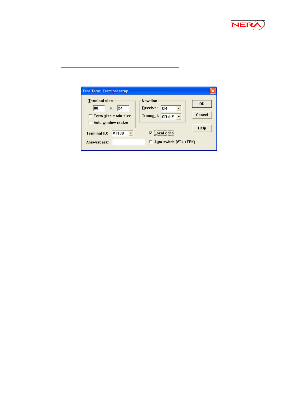
Nera SatLink Terminal User Guide
Appendix D. Telnet Client
A good freeware Telnet client is Terra Term Pro 2.3. The software can be download from the Terra Term
home page: http://hp.vector.co.jp/authors/VA002416/teraterm.html. Especially when running Telnet from
Windows XP it is recommended to use Terra Term instead of the built in Telnet Client in Windows XP,
since setting Local Echo in the Windows XP client does not seem to work.
Figure 21: Terra Term Terminal Setup
When starting Terra Term, please choose the menu Setup and then Terminal. Please enable Local echo as
shown in Figure 21. Then chose the menu Setup and then Save Setup to save this configuration.
Terra Term may as well be used as a replacement for HyperTerminal.
67
Page 68

Nera SatLink Terminal User Guide
Appendix E. Management via SNMP
Management of the Nera SatLink Terminal is supported via SNMP. For further information of SNMP
management and the MIBs available, please refer to [6] and/or contact the system operator.
68
Page 69

Nera SatLink Terminal User Guide
Appendix F. Changing pre-configured parameters
F.1 IP routes
To add an IP route use the CLI command
ip addroute <destaddr> <netmask> <next hop> <ifnum>
destaddr IP address of destination network or host
netmask Netmask for destination network
next hop IP address of the next router/host in the path
to the destination network/host
ifnum interface number on which route is to be added
(1=LAN, 3=Satellite)
Example:
ip addroute 0.0.0.0 0.0.0.0 10.10.21.254 3
will set the default route to be to the satellite interface with next hop IP address 10.10.21.254.
Note that the specified next hop IP address cannot be the same as the one attributed to the terminal’s DVB
interface.
Use the CLI command ip show to verify the setting and the CLI command save config to store
the setting in the flash.
IP routes can be deleted with the ip delroute <destaddr> <netmask> <next hop> command.
F.2 Default CW frequency
The transmission of a pure tone (CW) is supported for aiding the antenna fine adjustment as well as for
use during power calibration. A default frequency for CW transmission is stored in the Nera SatLink
Terminal configuration. This default frequency may be changed with the CLI command
dvb tx cwfreq <freq> where freq is the return link frequency [kHz].
Example:
dvb tx cwfreq 14123000
sets the CW frequency to 14.123 GHz.
Verify the new setting by using the CLI command dvb tx show, save the configuration by using the
CLI command save config.
69
Page 70
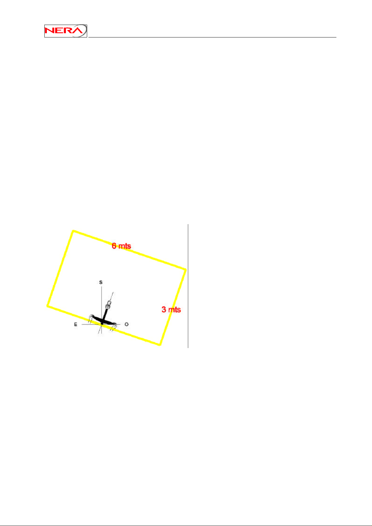
Nera SatLink Terminal User Guide
Appendix G. ODU assembly and mounting procedure
G.1 ODU installation steps
The ODU installation consists of the installations steps enumerated below:
1. Choice of antenna site
2. Assembly of front-end (Feed-horn, LNB unit and transmitter)
3. Assembly and installation of the antenna
4. Elevation and azimuth adjustment of antenna
5. Polarisation alignment
6. Line-up procedure including polarisation alignment and power adjustment of the Nera SatLink
Terminal.
The purpose of this Appendix is to describe the ODU assembling and mounting process, more detailed
procedures are given in Section 6.3 and Appendix H for terminal line up.
G.2 Choice of antenna site
The parabolic antenna can be installed on a roof, a wall, a terrace, in a garden or another suitable place
where the sight towards the satellite is not blocked by obstacles like trees, buildings or hills.
A free space is recommended in front and to both sides of the antenna as shown on the figure. However,
another antenna may be placed closer side by side. While transmitting, no person should be directly in
front of the antenna.
70
Page 71
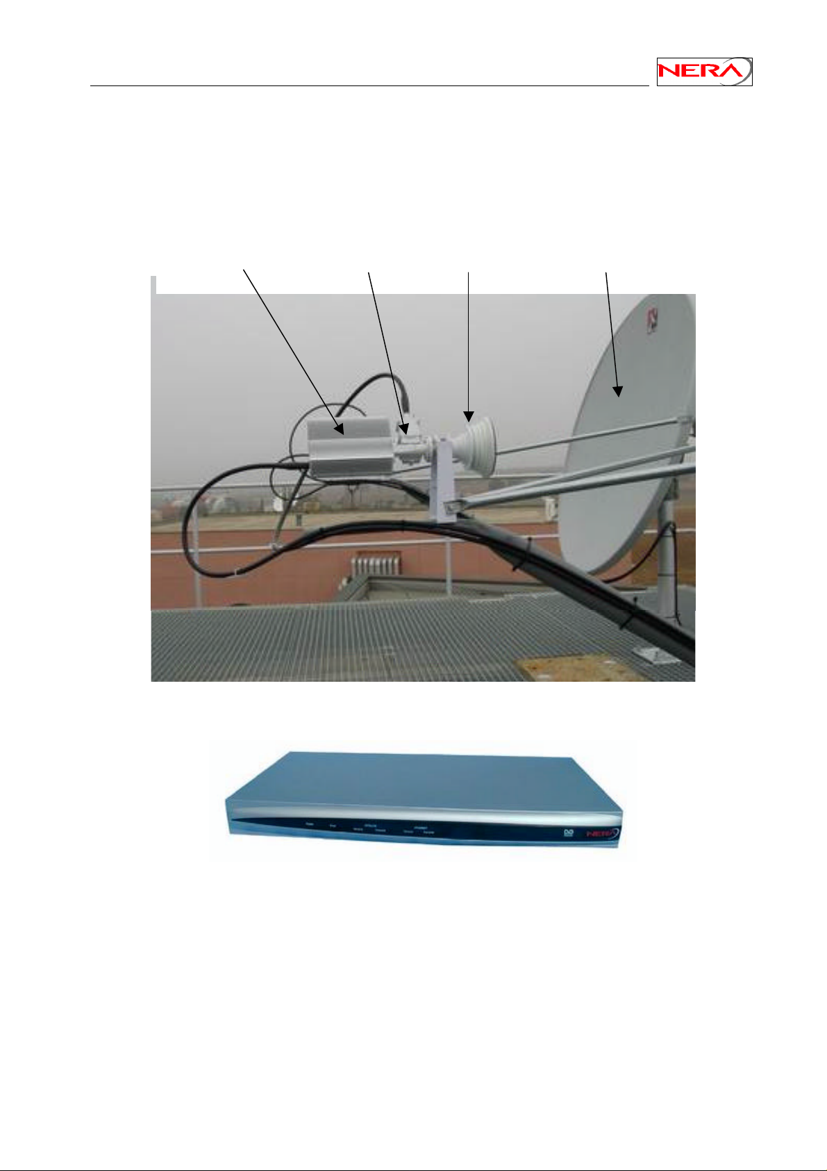
Nera SatLink Terminal User Guide
Feed-horn
Antenna
Azimuth
G.3 ODU basic components
The ODU comprises the antenna with feed-horn and mounting structure, a LNB unit with OMT and Txreject filter and a transmitter (BUC). Two cables with F-connectors, one for Tx and one for Rx are
connecting the ODU to the IDU.
BUC
Block Up Converter
LNB
Low Noise Block
Amplifier
ODU configuration
SatLink 1900.
71
Page 72
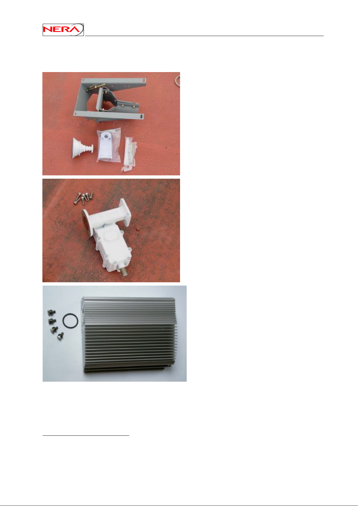
G.4 Assembly of LNB unit, transmitter and feed-horn
The main components are shown below:
Antenna reflector mounting and feed-horn
with supporting structure and screws.
Nera SatLink Terminal User Guide
LNB unit15 with screws.
Nera SatLink 3000 Transmitter with o-ring
and screws.
15
RF signals are received and transmitted at orthogonal polarisations, thus the LNB unit includes an
OMT (Ortho-Mode Transducer). The feed-horn is connected to the circular wave-guide (18.5 mm in
diameter, C120) while the transmitter is connected to the rectangular waveguide (R120, WR75,
UBR120).
72
Page 73
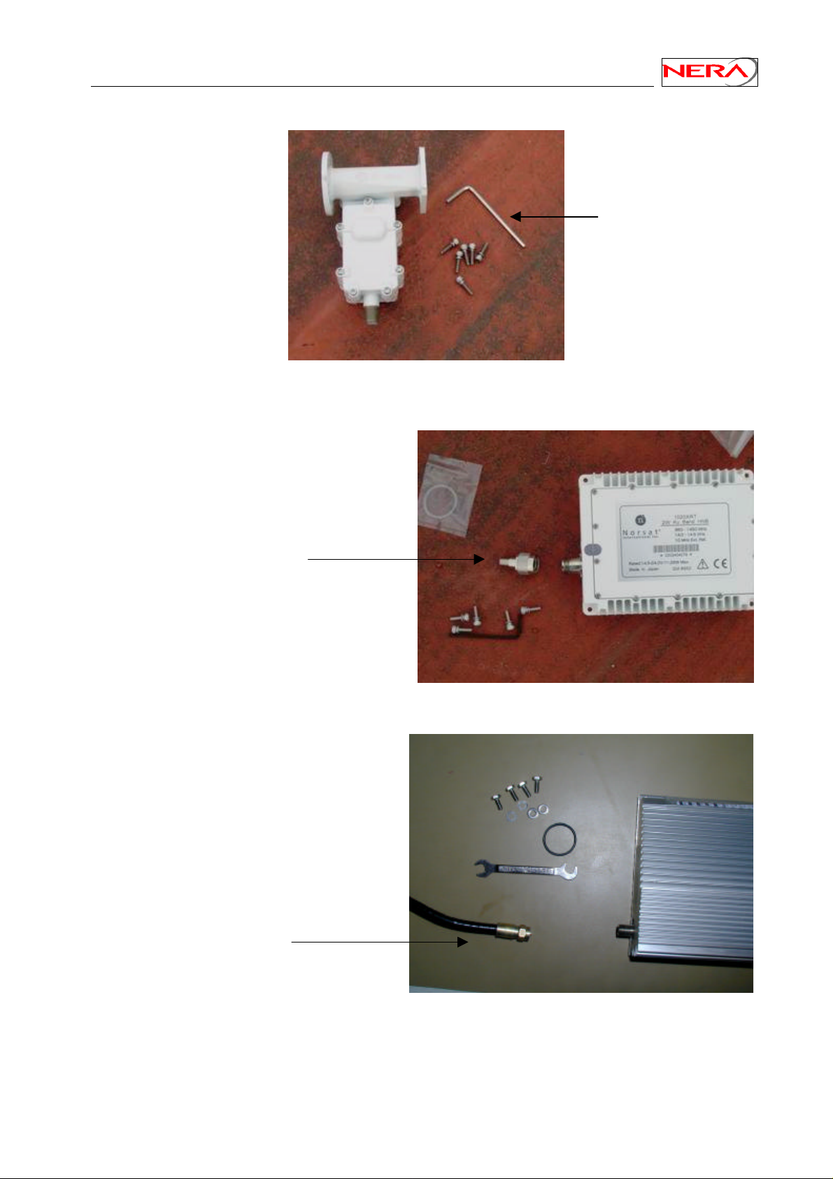
Nera SatLink Terminal User Guide
Allen key
No transition required
An Allen key is used to fasten the screws.
The Norsat 1010/1020XRT transmitters have a female N-connector as input connector, while the Txcable is usually mounted with a male F-connector. Hence, a waterproof adapter from male N-connector to
female F- connector must be used between the TX cable and the BUC connector.
Transition connector
The Nera SatLink 3000 transmitter has a female F-connector as input connector, therefore no transition is
needed with the TX cable.
73
Page 74
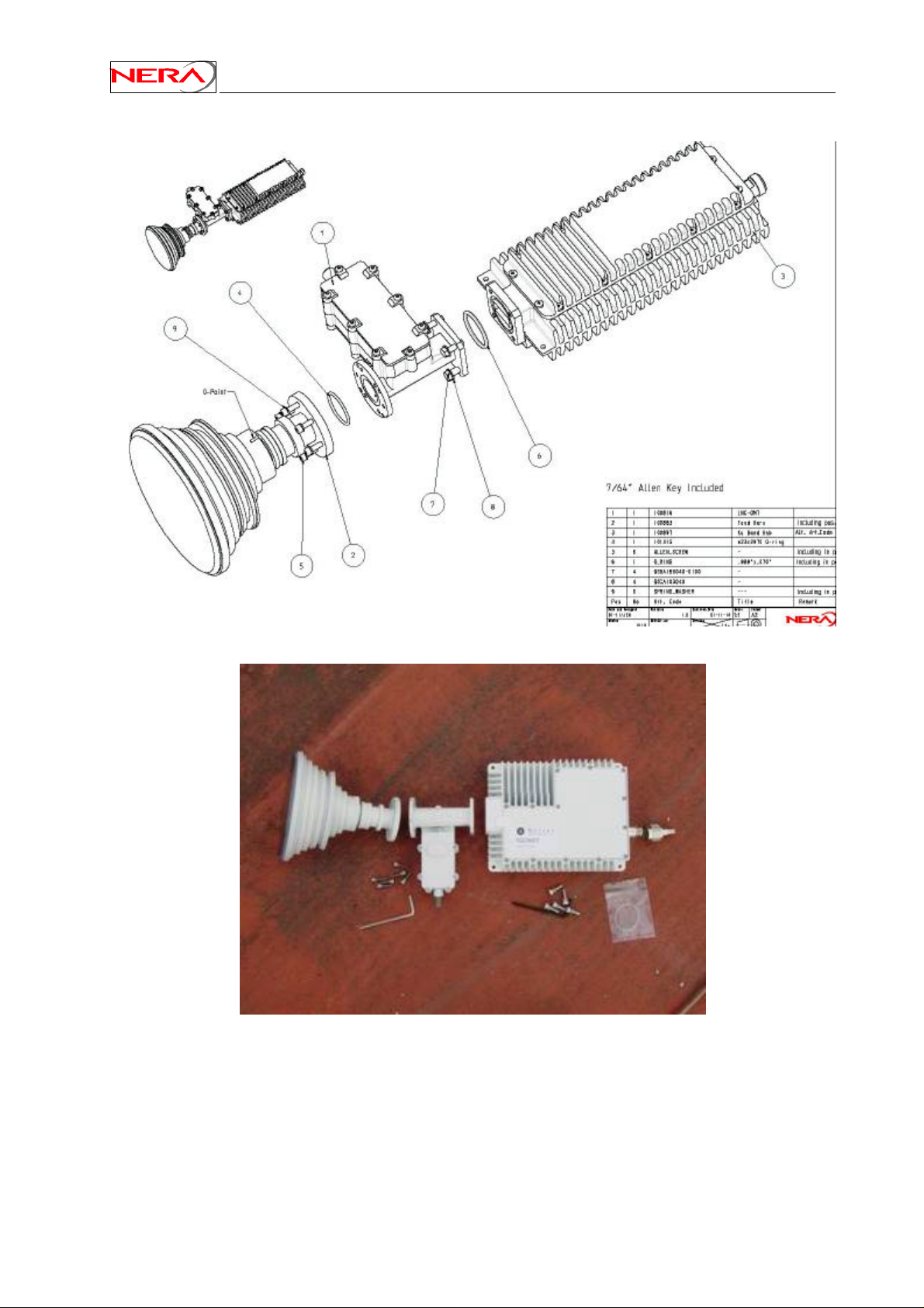
An assembly drawing with a Norsat 1020XRT transmitter is shown below:
Nera SatLink Terminal User Guide
74
Page 75
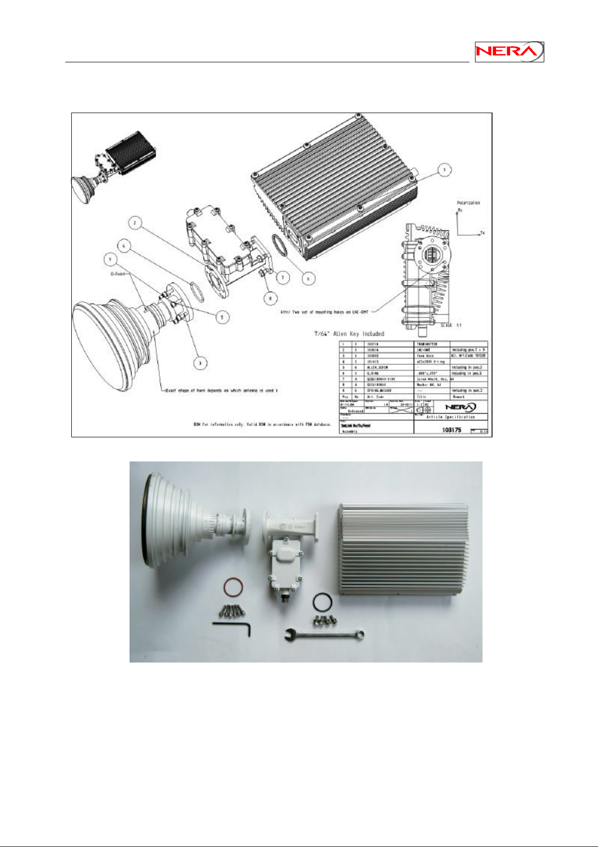
Nera SatLink Terminal User Guide
An assembly drawing with a Nera SatLink 3000 transmitter is shown below:
75
Page 76
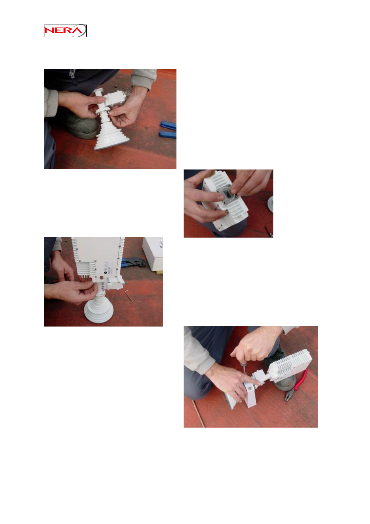
The different assembly steps are shown below:
Insert an o-ring at the WR-75 wave-guide
interface on the transmitter.
Nera SatLink Terminal User Guide
Connect the feed-horn with the LNB unit using the
correct screws. Remember the o-ring.
Mount the feed support structure on the feedhorn.
Connect the transmitter to the LNB unit using the
correct screws.
76
Page 77
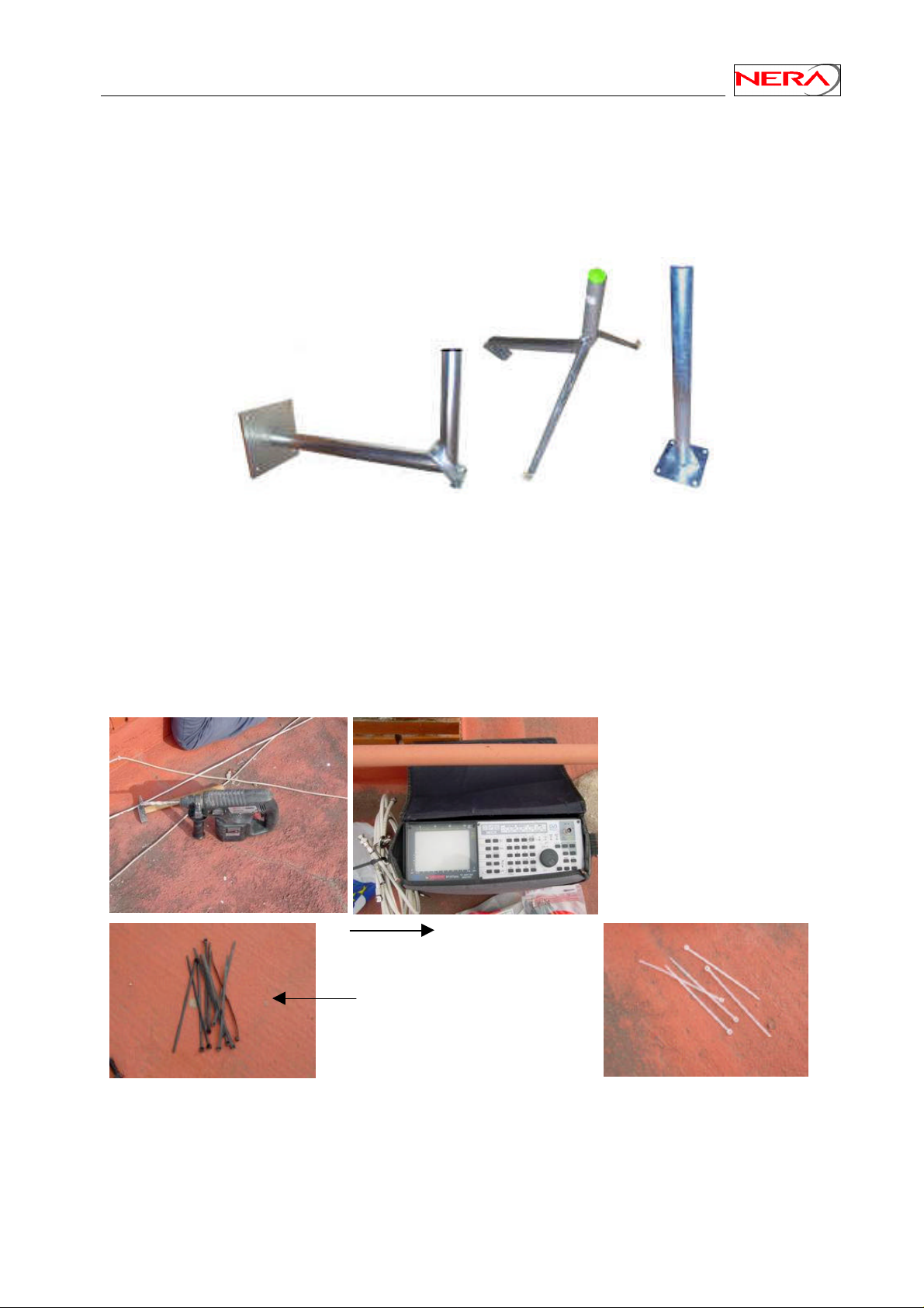
Nera SatLink Terminal User Guide
G.5 Assembly and installation of the antenna
Different mounting structures for antennas are shown below. From the left-hand side, we have an Lshaped wall-mount, a three-leg mount and a standard straight mount. The tube diameter is 76 mm. For a
correct mounting the surface must be vertical or horizontal respectively.
Non-penetrating roof-mounting structures (requiring no screws or bolts) may also be used if the customer
do not want to penetrate the roof. The foot can be rectangular, “H-shaped” or have another suitable form.
It must be loaded with at least 75 kg depending on the antenna size and maximum wind force.
The tools include a screwdriver, spanners of correct size (or an adjustable spanner) and a spirit level (if
necessary). Cable straps are used to fasten the cables. A compass, a satellite finder, and a spectrum
analyser (optional) are used to position and adjust the antenna. It is an advantage to be able to measure
BER on the received signal when adjusting the antenna.
Tools and measurement
equipment.
Out-door straps used to fasten
the cables. Do not use in-door
straps (white) to fasten cables
outside the building.
77
Page 78
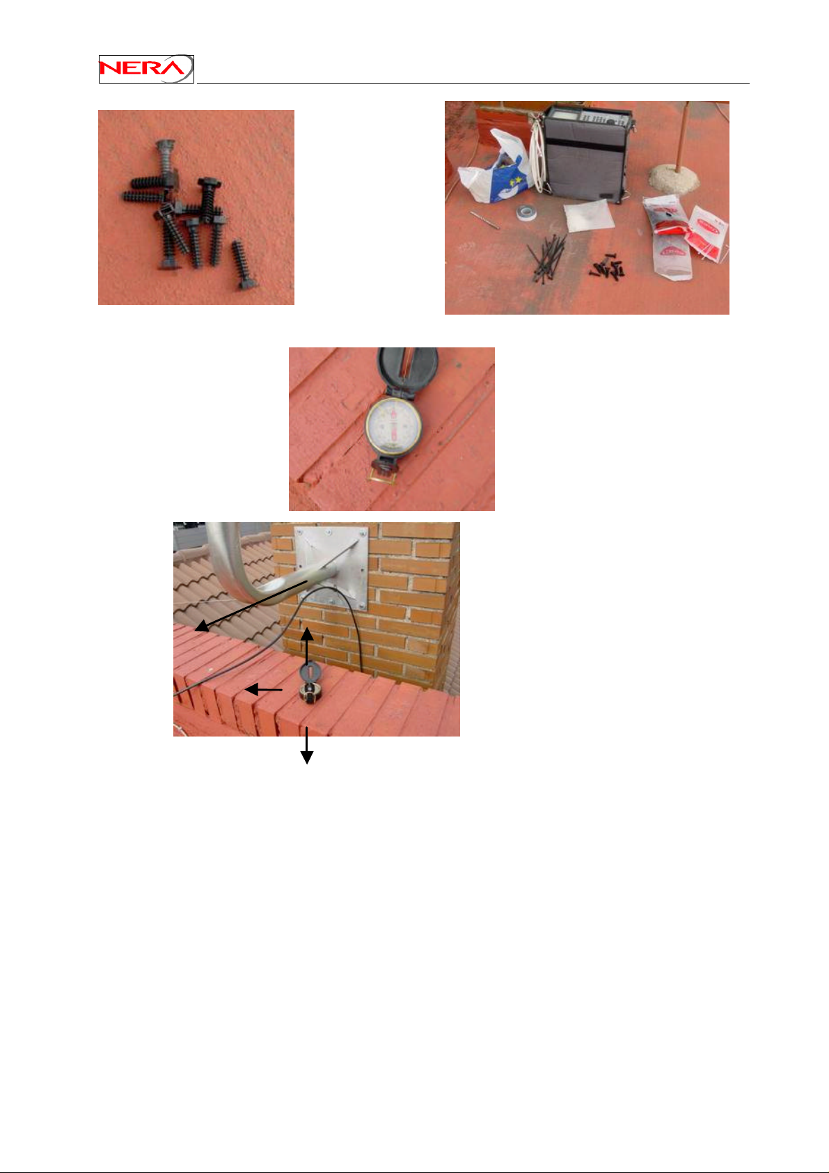
Bolts and
N
S
equipment.
Nera SatLink Terminal User Guide
SW
Compass
Check the visibility towards
the satellite.
W
78
Page 79
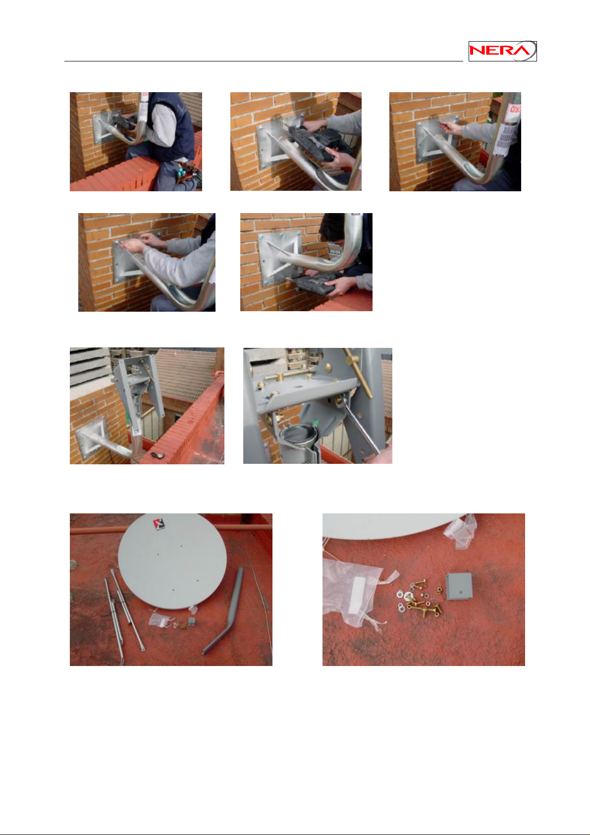
Nera SatLink Terminal User Guide
Installation of an L-shaped wall-mount on a pipe:
The mount must be fixed to
the wall and levelled so the
upper part of the tube is
vertical.
The antenna az/el mount is fastened to the vertical tube:
Point the az/el mount in
the approximate right
direction and fasten the
4 bolts (as shown).
Unpack the antenna and check the components: Parabolic reflector, feed- mount, 4 rods (2 long and 2
short), a U-shaped profile, bolts, washers and nuts.
79
Page 80
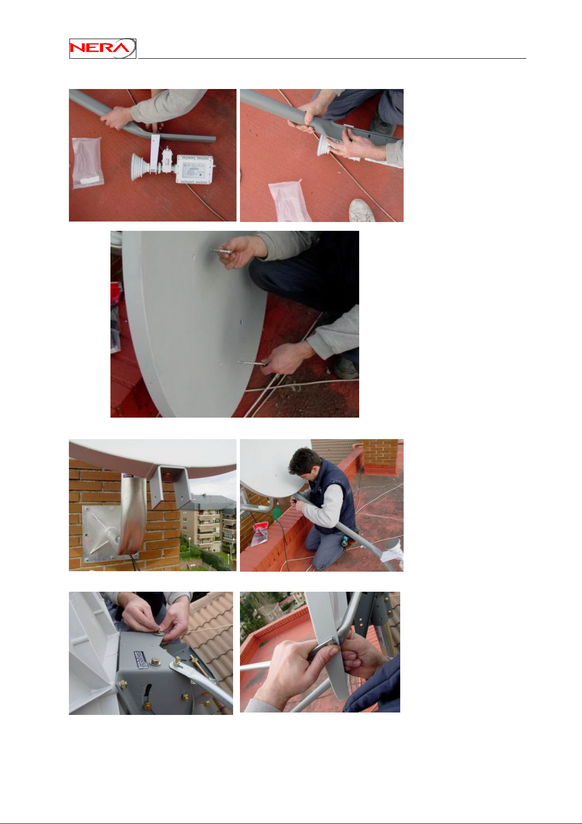
Continue the installation process:
Nera SatLink Terminal User Guide
Fasten the feed-horn,
LNB and transmitter to
the feed-mount.
Fasten the parabolic
reflector to the az/el
mount.
80
Fasten the U-shaped
profile to the reflector and
connect the feed-mount.
Fasten the short support
rods to the az/el mount
and connect them to the
back of the antenna.
Fasten the long rods to the
side of the reflector.
Page 81
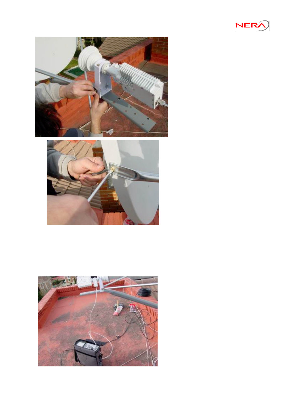
Nera SatLink Terminal User Guide
Connect the long support rods to the
feed-horn mount.
Adjust the position of the
transmitter (coarse adjustment) to
horizontal or vertical polarisation
depending on the satellite
transponder you are going to use.
Tighten the bolts.
If it is possible, connect an earth-grounding cable to the antenna feed-mount.
G.5.1 Elevation and azimuth adjustment of antenna
Continue with the antenna adjustment in elevation and azimuth. Connect the satellite finder (or the
spectrum analyser) to the LNB.
• The LNB must be fed with 18VDC.
To select the high band frequency
band, a 22 kHz tone must as well be
applied.
• RF- frequency band (input):
Low band: 10.7-11.7 GHz
High band: 11.7-12.75 GHz
• IF- frequency band (output):
Low band: 950-1950 MHz
High band: 1100-2150 MHz
81
Page 82
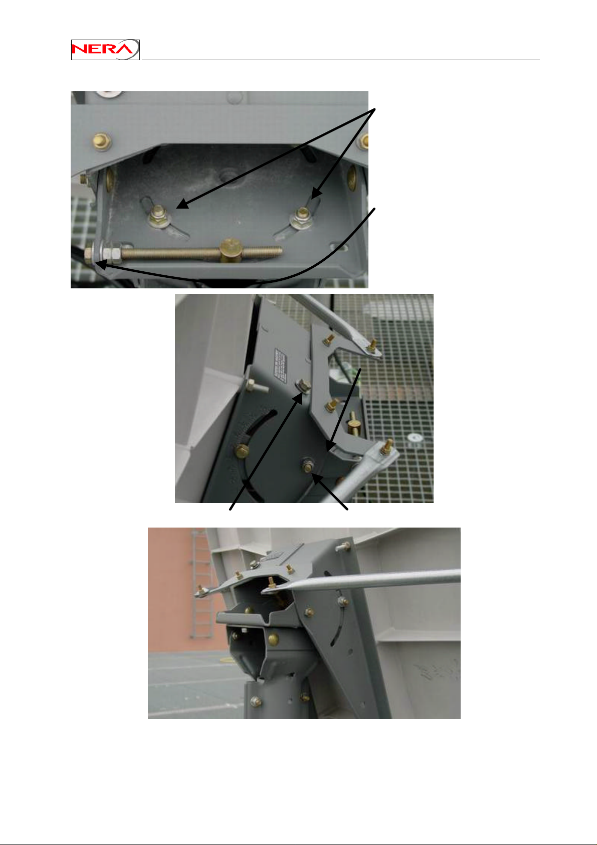
The peaking of the antenna by adjustment of azimuth and elevation:
Nera SatLink Terminal User Guide
Coarse adjustment of azimuth.
Loosen the bolts and adjust.
Alternatively, rotate the complete
antenna on the vertical rod.
Fine adjustment of azimuth.
Loosen the second nut and adjust.
Fine adjustment of elevation.
Coarse adjustment of elevation. Loosen the bolts
and adjust.
First, perform a coarse adjustment in azimuth and elevation and monitor the signal level on the satellite
finder or the spectrum analyser. Look at the spectrum analyser and check if you have found the right
82
Page 83
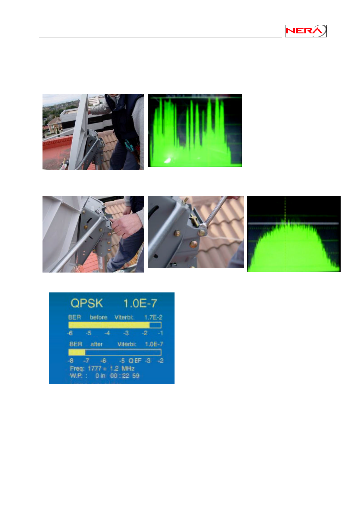
Nera SatLink Terminal User Guide
satellite (the carriers are those you expect). If the polarisation is not well aligned, you will also see the
carriers on the orthogonal polarisation.
Then, continue with the fine adjustment in elevation and azimuth. It is recommended that the span on the
spectrum analyser cover a single transponder. The resolution can be increased for the fine adjustment.
Coarse adjustment of the
antenna.
A frequency spectrum as seen
on the spectrum analyser.
(HISPASAT 30°W, upper band,
vertical polarisation)
Fine adjustment in elevation and azimuth observing one transponder.
.
If your measurement equipment can measure
BER, you can use this for adjustment. Select the
transponder you want to use. (In the example: IF
centre-frequency 1777 MHz or RF centrefrequency 12.377 GHz).
The minimum BER without coding should be
better than 1E-4 and 1E-7 after Viterbi coding
for QPSK. If you do not reach these figures, try
to re-adjust.
83
Page 84
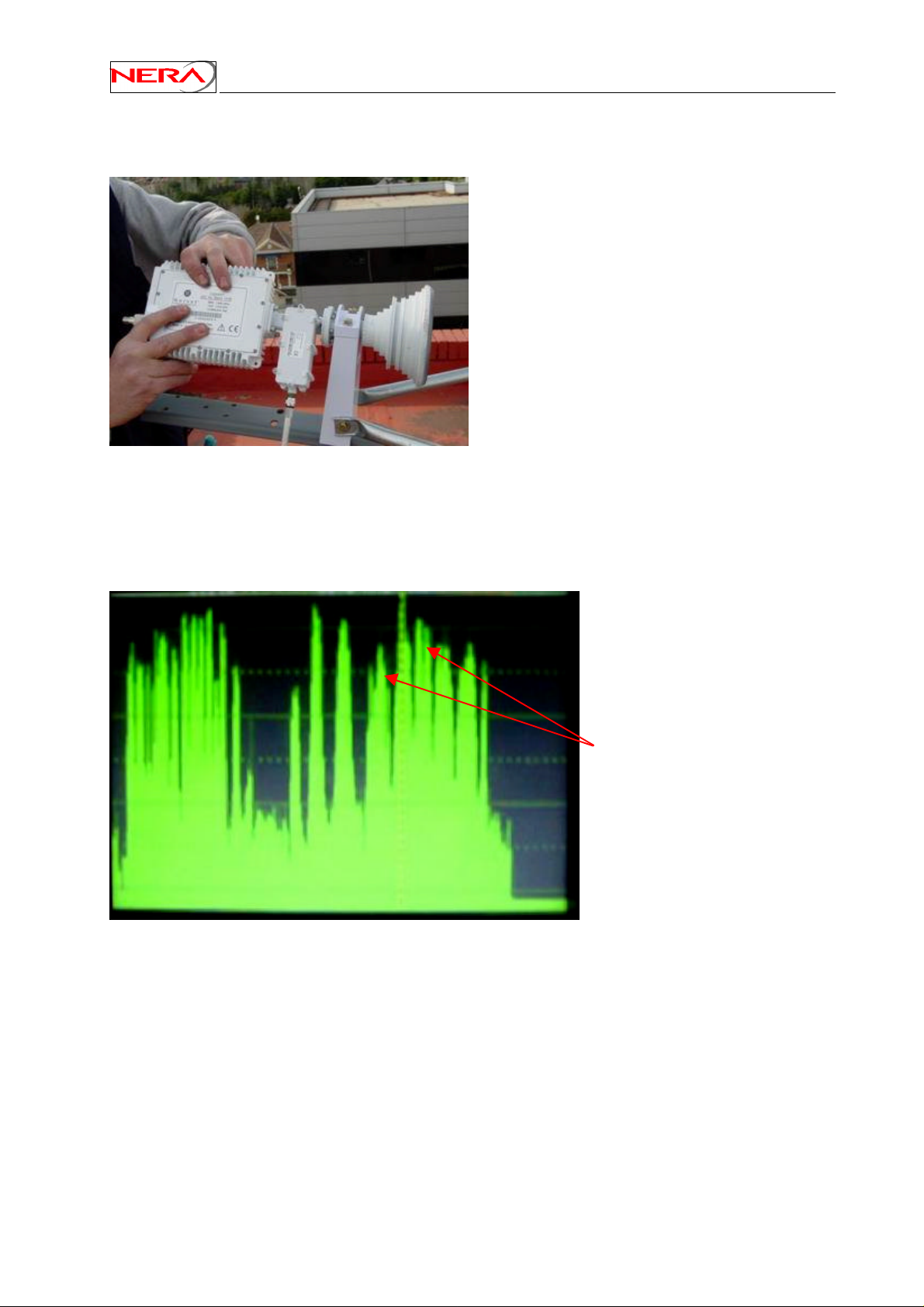
Nera SatLink Terminal User Guide
G.5.2 Polarisation alignment
Rotate the complete feed-system (horn, LNB and
transmitter) very slowly and carefully in one
direction away from the coarse polarisation
alignment. Monitor the spectrum-analyser and
observe the carriers on the opposite polarisation.
Correctly adjusted, the carriers should disappear
or have a much lower level than the carriers with
the correct polarisation. Rotate in the opposite
direction if you do not observe disappearing
carriers.
The polarisation alignment must be performed with a high degree of accuracy. Note that the crosspolar discrimination (XPD) requirement on transmitted signal may vary depending on the satellite
operator. During line-up, the control centre of the satellite operator will check if the terminal’s
XPD is sufficient and eventually ask the ODU installer to proceed with fine adjustment until the
XPD requirement is achieved.
Spectrum before polarisation
fine adjustment.
84
Page 85
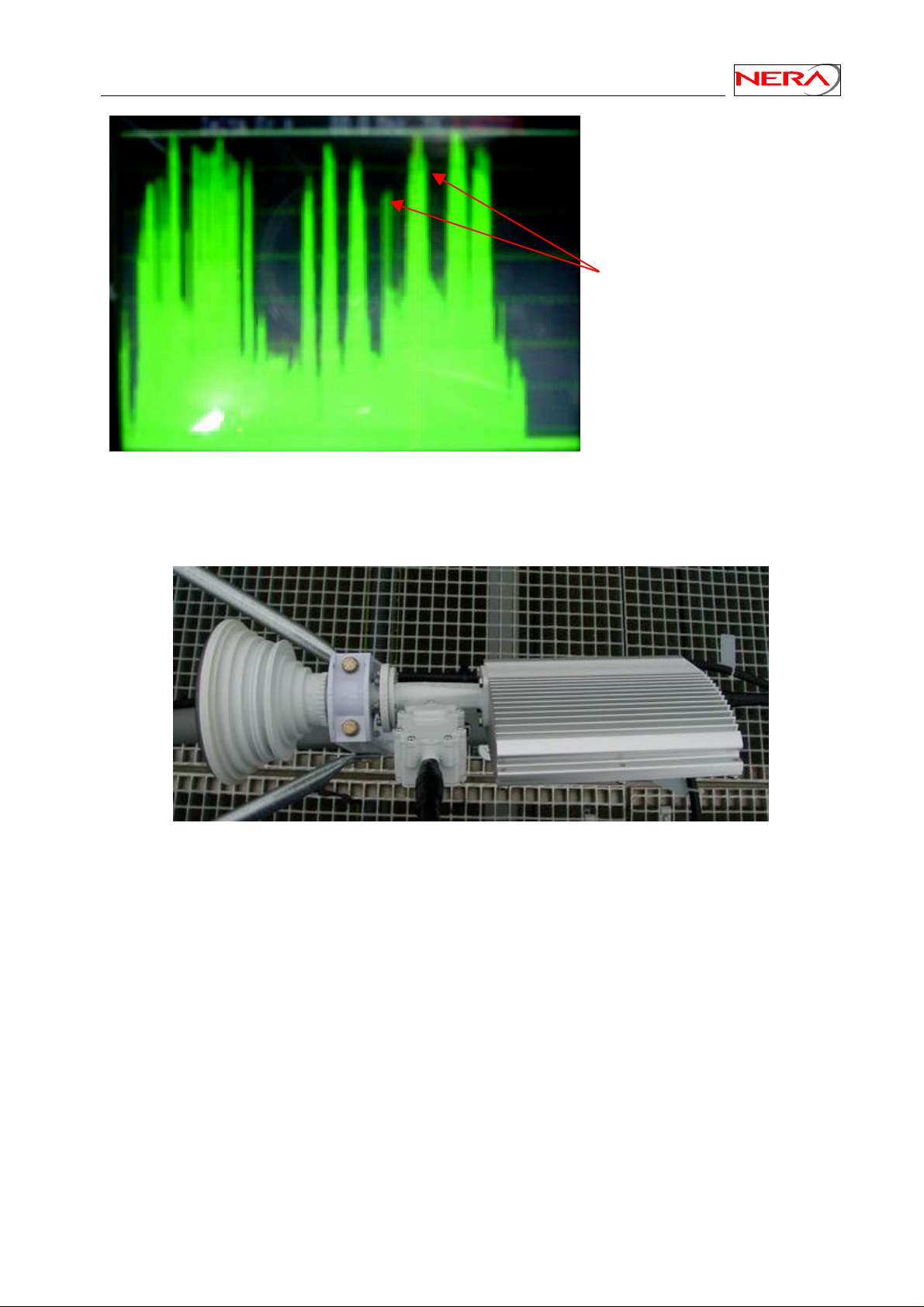
Nera SatLink Terminal User Guide
After polarisation adjustment.
The carriers have disappeared.
Tighten all the bolts and screws properly and have a final check on signal level and polarisation. Below
an ODU with a Nera SatLink 3000 transmitter is shown with the additional polarisation tilt visibly.
85
Page 86
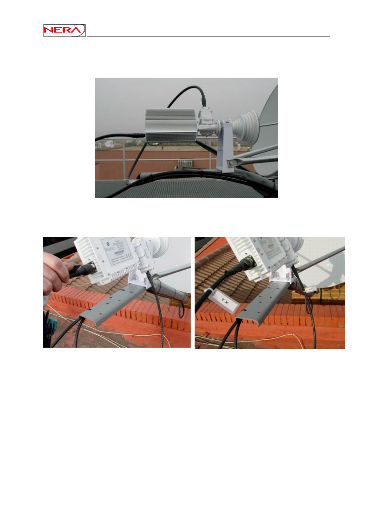
G.5.3 Additional work
The Rx- and Tx-cables should be strapped to the feed-mount.
Nera SatLink Terminal User Guide
Finally, the F-connectors must be protected against rain and humidity. Use a self-vulcanising tape suitable
for out-door use. The cables must also be properly marked.
86
Page 87
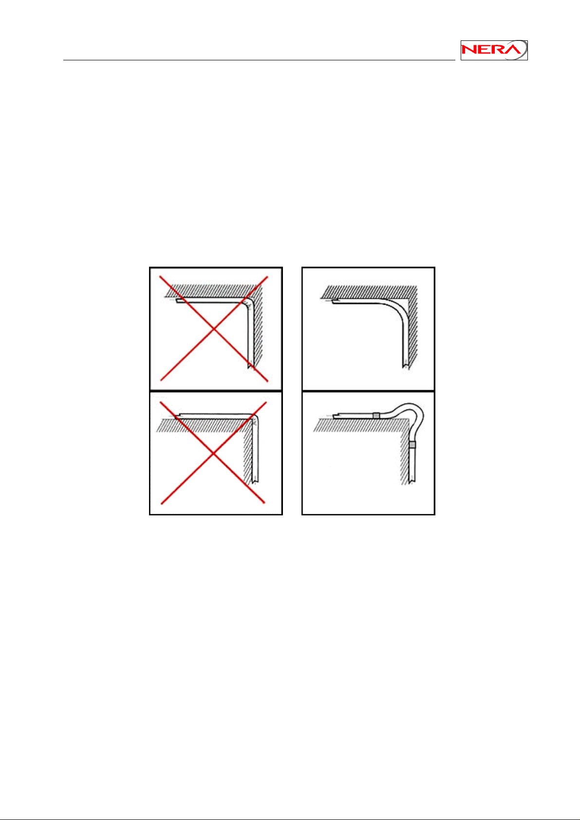
Nera SatLink Terminal User Guide
G.5.4 Cables
Nera recommends cables from Times Fiber. For cable lengths up to 62 m, Times Fiber series 6 (diameter
6.93 mm) can be used. For lengths up to 82 m, use series 11 (diameter 10.2 mm) and for longer lengths,
use series 500 (diameter 14.2 mm).
Important: Do not use amplifiers or attenuators on the TX-cable.
Use type “F” connectors for the cables.
The cable pulling from the ODU to the IDU must be performed according to the customer. Sharp bends
on the cables must be avoided (see figure below).
87
Page 88

Nera SatLink Terminal User Guide
Appendix H. Using other BUCs than the Nera SatLink 3000
The Nera SatLink Terminal can be used together with the Norsat 1010/1020XRT and Invacom TUL-204
BUCs. The BUCs do not support DiSEqC communication and do not have a power detector to measure
the actual output power from the HPA. A more complicated procedure to calibrate the Tx output power
must then be run as described below.
H.1 Calibrating the IDU output power
This section describes how to calibrate the Tx output power when using one of the following ODU
transmitters:
• Invacom TUL-204
• Norsat 1010/1020XRT
• Nera SatLink 3000 revision 3.0 and earlier.
Please refer to section 6.3.2 for the description of the simpler calibration procedure for the Nera SatLink
3000 (revision 5.0 and newer).
Ensure that the Nera SatLink Terminal configuration procedure in section 6.2 has been performed.
Ensure that the Nera SatLink Terminal is configured to start the receiver (Rx) automatically, but not the
transmitter (Tx).
Enter the CLI command dvb rx autostart on to enable receiver automatic start.
Enter the CLI command dvb tx autostart off to disable transmitter automatic start.
Enter the CLI command dvb rx show. Verify that the parameter Auto Start is set to Enabled.
Enter the CLI command dvb tx show. Verify that the transmitter is Off and the parameter Auto
Start is set to Disabled. If the transmitter is On, use the command dvb tx logoff.
Enter the CLI command save config to save this configuration.
Ensure that the Tx and Rx cables from the Nera SatLink Terminal to the ODU are connected
Restart the SatLink Terminal (issue the CLI command restart), wait till the application has loaded, and
the Nera SatLink Terminal has locked to the received carrier. The receiver has successfully acquired the
forward link when the message Forward link up is displayed (see section 6.3.1 for further details).
Logon as the super user (user = root, factory default password = nera)
Call the control centre and have contact by phone for the following measurements.
Set up a continuous wave (CW) with the following command:
dvb tx cw on <pow> <freq>
where
pow = Transmitted IF power level from IDU in dBm.
This is an integer in the range –30 to +10. (Start with pow= -30)
freq = transmitted radio frequency in kHz. The frequency is only required the first time
the CW is turned on. Subsequent adjustment of the power level can be done
without entering the frequency.
88
Page 89

Nera SatLink Terminal User Guide
Example:
dvb tx cw on -30 14100000
will transmit a CW from the ODU output at 14.1 GHz with an IDU output power of –30 dBm from the
Nera SatLink Terminal.
Please check immediately with the control centre if they can detect the transmitted CW. If they are
not able to see the CW at the specified frequency and expected output power level, please power off
the Nera SatLink Terminal immediately.
The operator control centre will instruct you to adjust your power in positive or negative steps. Never
make power adjustments steps larger than 5 dB. Please update the transmitted power level using the
above dvb tx cw on command until the desired power level is measured at the control centre.
When the operator confirms that the correct power level has been reached, then turn off the CW
transmission with dvb tx cw off before storing this power level as the nominal IDU power level to be
used for transmission. Type the CLI command:
dvb tx outpow <tx output power>
where “tx output power” is the power level in dBm. Verify the setting by issuing the CLI
command
dvb tx show
and save the setting by issuing the CLI command
save config
In the following example a complete power correction routine is carried out.
Example:
dvb tx cw on -30 14100000
The operator instructs you to increase power by 5 dB (i.e. pow = -30 + 5 = -25). You type:
dvb tx cw on -25
The operator instructs you to decrease power by 3 dB. (i.e. pow = -25 - 3 = -28). You type:
dvb tx cw on -28
The operator instructs you to increase power by 1 dB. (i.e. pow = -28 + 1 = -27). You type:
dvb tx cw on -27
The operator confirms that the correct power setting is obtained. Confirm the nominal power setting by
storing this power level. To configure the nominal power level, turn off the CW transmission with:
dvb tx cw off
89
Page 90

and type the CLI command:
dvb tx outpow –27
Verify the setting by issuing the CLI command
dvb tx show
and save the setting by issuing the CLI command
save config
Nera SatLink Terminal User Guide
90
Page 91

Nera SatLink Terminal User Guide
Appendix I. The boot SW
The Nera SatLink Terminal has two SW applications installed:
1) Boot
2) DVB-RCS Application
The Boot SW is stored outside the file system and can be compared with the BIOS and MS-DOS on a PC.
It is used to have access to file system and the LAN when there is no application loaded on the Nera
SatLink Terminal.
The Boot SW is always loaded after powering on the Nera SatLink Terminal. But normally the user need
not care about the boot SW since the DVB-RCS application is loaded by default.
The boot-loader can only be accessed via RS-232 as described in Appendix B. After power on, an output
similar to this is displayed on the HyperTerminal:
Nera SatLink Boot-loader
- SW ID 101225, Revision 1.8.0.2
File system initialised
Press return to enter boot-loader
In order to logon and use the boot SW, press return (the software will wait 10 seconds before
automatically loading the DVB-RCS application):
1. When Login is displayed type the user name root
2. When Password is displayed type nera
16
In the boot-loader there is available a minimal CLI supporting the file system commands and access to the
LAN. Type ? (question mark) to display the available CLI commands.
16
Nera is the factory default password and might have been changed by the user
91
Page 92

Nera SatLink Terminal User Guide
Appendix J. Debugging network connections
Ping is a useful tool to debug network connections.
A ping test can be done from a PC connected to the Ethernet port of the Nera SatLink Terminal (e.g. from
Microsoft command prompt).
Use the following commands:
1. Ping the gateway router (e.g. ping 10.10.10.1). If successful, the connection to the gateway is
OK. If the gateway router can not be reached please check that the Nera SatLink Terminal has
lock on the forward link and is logged on to the DVB-RCS network.
2. Ping a web site, e.g ping www.nera.no. If successful the connection to Internet is OK.
If not OK check that the PC DNS IP address is correct (try also to ping a known IP address on the
Internet, e.g. ping 195.204.181.169)
3. If pinging the GW router does not work, try to ping the Ethernet interface IP address of the Nera
SatLink Terminal (e.g. 10.10.20.1). If not OK please check the Ethernet cable and that the Nera
SatLink Terminal’s Ethernet port is operating in the correct mode (HUB for direct PC to Nera
SatLink Terminal connections using a straight Ethernet cable). If the Ethernet connection is OK
then check the IP configuration and routing table of the PC (e.g. type the MS-DOS commands
ipconfig and route print) and check the IP configuration of the Nera SatLink Terminal
(use the CLI command ip show.)
The following commands may also be useful:
• ping –t <ipaddr> start a continuous ping test towards the specified IP address in order to gather
statistics
• use ctrl-break to read statistics during test (This option is not supported by all Windows operating
systems)
• use ctrl-c to stop the test
92
Page 93

Nera SatLink Terminal User Guide
Appendix K. Collecting information if a problem occurs
If a problem occurs with the DVB-RCS terminals for which support might be needed, having the
information listed below available will be helpful.
1. The terminal log from the HyperTerminal Window.
If possible log the output from the terminal to the HyperTerminal Window when the problem occurs.
The output from the HyperTerminal window can either be copied to a text file by setting the capture
text options in HyperTerminal (-> Transfer -> Capture Text), or copied directly from the
HyperTerminal windows using the normal Windows copy function (CTRL+C) and then pasted in a
text editor like Notepad or Word to generate a file suitable for being included as an e-mail
attachment.
When logging to HyperTerminal please issue the following CLI commands and capture the output.
ip show
ip show -mcast
dvb tx show
dvb tx show -capacity
dvb rx show
dvb rx show -pid
dvb pos show
odu show
sw show
log show
dir
2. The terminal configuration file, config.txt.
If possible please upload the configuration file to a PC with a TFTP server using the CLI command
upload config.txt <TFTP-Ipaddress> [<remotefilename>] where TFTP-Ipaddress is
the IP address for the TFTP server, and remotefilename is an optional parameter specifying the
filename to store the file as on the TFTP server if a different name than config.txt is wanted. Please
refer to Appendix C for an example of how to install and set up a TFTP server.
If it is not possible to upload the terminal configuration file to a TFTP server the config.txt file might
be dumped to the RS-232 port / HyperTerminal by using the CLI command type config.txt.
The output from the HyperTerminal Windows can then be copied to a text file or dumped using the
capture text feature of the HyperTerminal.
93
Page 94
Nera SatLink Terminal User Guide
Appendix L. TCP enhancement and tuning
The Transmission Control Protocol – TCP now is used by most applications on the Internet (e.g. HTTP,
POP3 and FTP). The protocol is designed for controlling the end-to-end flow of data over an IP network,
by imposing error control and congestion control. When using the protocol in satellite networks, the
mechanisms designed for improving the throughput in terrestrial networks, is acting counterproductive
due to the RTT delay. The problem areas of TCP are mainly:
• Window size algorithm: the amount of data a sender will transmit is limited by a sliding window
protocol. The window is controlled by the reception of acknowledgement packets. This regulation
loop is very slow in satellite networks, and results in poor performance.
• Slow start/ Congestion avoidance algorithm: When the protocol entity detects congestion (or
rather detect a situation perceived as congestion), the sending buffer is reduced in what is called
the slow start/congestion avoidance algorithm. Packet loss is interpreted as congestion by the
TCP entity. This means a high impact on bandwidth of a simple packet error.
• Backchannel bandwidth: TCP needs a certain bandwidth for the back-channel in order to transmit
acknowledgements. The back channel will limit the forward channel. This is a limitation for
asymmetric channels like satellite access links.
In order to counter act some of these shortcomings, several actions can be taken using the standard TCP
(and IP) features and parameters. RFC 2488 recommends the following actions:
• Path-MTU Discovery: is a feature of the underlying IP network. The purpose is to determine the
maximum packet size a connection can use on a given network path without being subjected to IP
fragmentation. Fragmentation requires more CPU overhead in the intermediate routers, and will
increase the delay. The mechanism utilises the IP header “don’t fragment” bit, and transmits packets
with decreasing size (from the maximum allowed on the local network) until the packets are received
correctly by the destination. In the satellite network it is important to tune the packet size to the
MPEG frames used on the link.
• FEC – Forward Error Correction: is utilised.
• TCP congestion control: The Slow start and congestion avoidance algorithms described above are
limiting satellite operation. However they are required by the standards, and can not be avoided. The
Fast Retransmit and Recovery mechanisms are somewhat reducing the effect of the slow
start/congestion avoidance, and are both part of all current TCP/IP implementations.
• TCP Large windows: a path with a high bandwidth x delay product like the satellite link, needs a long
transmission window in order to utilise the bandwidth. The throughput of TCP is limited by the
formula: throughput = window size / RTT
• Standard window size for TCP is 65 535 Bytes which means that the maximum throughput on a satellite link is: 65535 B
/560 ms = 936.2 kbit/s. This is below the forward link capacity. By increasing the window size higher performance can be
achieved. For web browsing this is normally not a limitation, as more TCP connections are operating at the same time
(normally 4 for HTTP 1.0). For newer HTTP 1.1 browsers, this may become a limitation, as several HTTP request/reply
sessions can be multiplexed onto the same TCP connection (require support from server).
• Window scaling: To enable window sizes above 64KB, the window scaling option according to RFC
1323 should be implemented to avoid sequence number overlap (as 16 bits can only represent 65535
at the maximum). And the accompanying protocols
• RTM – round trip measurement: more refined round trip measurement by means of timestamps.
• PAWS – Combination of timestamps and sequence numbers to detect wrapped sequence
numbers.
• Selective Acknowledgement: Basic TCP uses the goback-N acknowledgement scheme. This means
that an acknowledgement applies to all transmissions up to the ack number. This means that when
multiple packets are lost, all packets transmitted after the erroneous transmission must be
retransmitted. By employing a selective acknowledgement scheme, the ACK only applies to a single
segment. The SACK option as described in RFC 2018 points out which segments needs to be
retransmitted. This has effect only for large windows (probability for substantial retransmissions).
94
Page 95
Nera SatLink Terminal User Guide
Appendix M. List of events that may be logged
The following are the most common events that may be shown in the log from the Nera SatLink
Terminal. Use the CLI command log show to display the list of events stored in memory and the CLI
command type activeLog.txt to display the list of events stored on the flash file system.
Events of type Major will normally cause disruption in the data transfer, while events of type Critical
normally will require user intervention in order to restore the data communication with the DVB-RCS
gateway.
Event Severity User action
required
Memory Allocation
Failed
Memory Pool
Allocation Failed
CRU Buffer
Allocation Failed
NCR lock lost Major None The Nera SatLink Terminal must log off, but
CMT not received Major None The Nera SatLink Terminal must log off, but
Logon retry timeout Minor None The Nera SatLink Terminal was not able to
Physical link
Synchronisation alarm
Logon failure Major None The Nera SatLink Terminal was not able to
GW Busy Major None The DVB-RCS gateway does not allow the
Major Restart terminal The Nera SatLink Terminal software
Major Restart the
terminal
Major Restart the
terminal
Major None The link to the DVB-RCS gateway is broken.
Comment
application failed to allocate memory. Note
that this may be a normal scenario. If the
service is corrupted, reboot the terminal. If
the problem persist, please contact the DVBRCS gateway operator.
The Nera SatLink Terminal software
application failed to allocate memory. Note
that this may be a normal scenario. If the
service is corrupted, reboot the terminal. If
the problem persist, please contact the DVBRCS gateway operator.
The Nera SatLink Terminal software
application failed to allocate memory. Note
that this may be a normal scenario. If the
service is corrupted, reboot the terminal. If
the problem persist, please contact the DVBRCS gateway operator.
will automatically try to reacquire the
forward link and log on again
will automatically try to log on again.
log on to the DVB-RCS gateway. After a
timer has expired the Nera SatLink Terminal
will retry to log on to the DVB-RCS
gateway.
The Terminal will automatically try to logon
again to the DVB-RCS Gateway. If the
problem persists, contact the system operator.
log on to the DVB-RCS gateway. After a
timer has expired the Nera SatLink Terminal
will retry to log on to the DVB-RCS
gateway.
Nera SatLink Terminal to log on. After a
timer has expired the Nera SatLink Terminal
will retry to log on to the DVB-RCS
gateway.
95
Page 96
Nera SatLink Terminal User Guide
Event Severity User action
Comment
required
Logon denied Critical Call DVB-RCS
gateway operator
The Nera SatLink Terminal is not allowed to
log on to the DVB-RCS gateway
GW initiated logoff Major None The DVB-RCS gateway operator has forced
the Nera SatLink Terminal to logoff.
Fine Sync failure Major None The Nera SatLink Terminal was not able to
enter the fine synchronisation state when
trying to log on. After a timer has expired the
Nera SatLink Terminal will retry to log on to
the DVB-RCS gateway.
ODU power on failure Critical Check that cable
to ODU is
connected and
that the Terminal
is configured for
the correct ODU
The Nera SatLink Terminal is not able to
establish DiSEqC communication with the
ODU. Possible causes may be:
- Cable to ODU not connected
- IDU not configured for correct ODU
- The ODU must be repaired
(type CLI
command odu
show)
Logon successful Normal None The Nera SatLink Terminal succeeded to log
on to the DVB-RCS gateway
Terminal Logoff Normal None This event is logged on after a user initiated
logoff.
Entering hold state Major None The DVB-RCS gateway operator has put the
Nera SatLink Terminal in Hold-state. When
the Nera SatLink Terminal is in the Holdstate it is not allowed to try to log on to the
DVB-RCS gateway. To get an explanation of
why the Nera SatLink Terminal has been put
in Hold-state please contact the DVB-RCS
gateway operator.
Leaving hold state Normal None The Nera SatLink Terminal is again allowed
to log on to the DVB-RCS gateway.
Tuning failure
configured transport
stream
Major Check RX
configuration
(frequency,
symbol rate).
Check that cable
to LNB is
properly
The Nera SatLink Terminal is not able to
acquire lock on the initial forward link
transport stream (the one that is configured at
the Nera SatLink Terminal). If the problem
does not disappear within 10-60 minutes
please contact the DVB-RCS gateway
operator.
connected.
Tuning failure NIT
transport stream
Major None The Nera SatLink Terminal is not able to
acquire lock on the forward link transport
stream signalled in the NIT. If the problem
does not disappear within 10-60 minutes
please contact the DVB-RCS gateway
operator.
Tuning failure RMT
transport stream
Major None The Nera SatLink Terminal is not able to
acquire lock on the forward link transport
stream signalled in the RMT. If the problem
does not disappear within 10-60 minutes
please contact the DVB-RCS gateway
operator.
96
Page 97
Nera SatLink Terminal User Guide
Event Severity User action
Comment
required
Missing Table Major None The Nera SatLink Terminal is not receiving a
mandatory DVB-S/DCB-RCS table on the
forward link. If the problem does not
disappear within 10-60 minutes please
contact the DVB-RCS gateway operator.
TCT Inconsistency Critical Restart Terminal There is an error in the received TCT table.
If the problem does not disappear within 10-
60 minutes please contact the DVB-RCS
gateway operator.
ODU Communication
Failure
Critical Check that cable
to ODU is
connected and
that the Terminal
is configured for
the correct ODU
The Nera SatLink Terminal is not able to
establish DiSEqC communication with the
ODU. Possible causes may be:
- Cable to ODU not connected
- IDU not configured for correct ODU
- The ODU must be repaired
(type CLI
command odu
show)
ODU Temperature
High
Major None The temperature in the ODU got too high. If
this happens several times without extreme
weather conditions the ODU must be sent for
repair.
ODU Temperature
Critical
ODU Short Circuit Critical Find and remove
LNB Short Circuit Critical Find and remove
ODU turned itself off Critical Restart terminal.
Critical Send ODU for
repair
cause of shortcircuit.
Restart terminal.
cause of shortcircuit.
Restart terminal.
If the failure
occurs again the
ODU must be
The temperature in the ODU has got too high
and the unit should be sent for repair.
The power supply to the BUC has been short-
circuited. After removing the cause for the
short-circuit the terminal must be restarted to
recover.
The power supply to the LNB has been short-
circuited. After removing the cause for the
short-circuit the terminal must be restarted to
recover.
The ODU has powered itself down – most
likely because it has detected a failure. If this
happens more than once the ODU must be
sent for repair.
sent for repair.
Tftp Server
uncreachable
Major Check IP
connection with
the TFTP server
The Nera SatLink Terminal is not able to
establish the connection with the TFTP
server. Likely to be an IP configuration or
network problem. Verify the IP connection
with the Tftp server with ping.
File not found Major Verify that the
file is present on
the TFTP server
The Nera SatLink Terminal is not able to
upload the file specified in the command
from the TFTP server. Verify that the file is
available on the TFTP server.
File transfer error Major Check available
space on file
system
The File transfer has been aborted either due
to an IP connection interruption between the
terminal and the TFTP serve or due to a lack
of available space on the terminal's file
system.
97
Page 98
Nera SatLink Terminal User Guide
Event Severity User action
required
SW checksum error Major Check validity of
*.tgz file.
Manual SW Upgraded
Major None It reports successful terminal software
completed
Automatic SW
Normal None The Nera SatLink Terminal has started
download started
Automatic SW
Normal None The Nera SatLink Terminal has successfully
download completed
Automatic SW
Major None The Nera SatLink Terminal failed to
download failure
Comment
A checksum error is reported on the
application *.tgz file downloaded during the
software upgrade. The will be deleted and the
software upgrade will be aborted. Please
contact the DVB-RCS gateway operator to
verify the integrity of the *.tgz file.
upgrade via TFTP.
automatic download via Multicast of a new
software version
downloaded a new software version via
Multicast. The Nera SatLink Terminal will
automatically restart and activate the new
software version.
download a new software version via
Multicast. If the problem persists within 2060 minutes, please contact the DVB-RCS
gateway operator.
98
Page 99

Nera SatLink Terminal User Guide
Appendix N. Compliance
The Nera SatLink 1000, 1900, 1901 and 1910 comply with the essential requirements of Article 3 of the
R&TTE 1999/5/EC Directive, if used for its intended use.
N.1 Safety (Article 3.1.a of the R&TTE Directive)
This equipment has been designed and tested to meet the requirements of the following standards:
• EN 60950:1992 (A1 + A2 + A3 + A4 + A11)
• EN 60215:1989
N.2 Electromagnetic compatibility (Article 3.1.b of the R&TTE Directive)
This equipment has been designed and tested to meet the requirements of the following standards:
• EN 301 489-1:2001 (V1.3.1)
• EN 301 489-12: 2000 (V1.1.1)
N.3 Efficient use of the radio frequency spectrum (Article 3.2 of the R&TTE
Directive)
This equipment has been designed and tested to meet the requirements of the following standard:
• EN 301 428:2001 (V1.2.1)
when installed together with the following outdoor unit equipment:
• Invacom LNB/OMT SPV - 1SM, P/N 100816
• Nera SatLink 3000, transmitter, P/N 100716
• Channel Master 1.2m Antenna, P/N 100882
• Channel Master 0.96m Antenna, P/N 100883
99
Page 100

 Loading...