

Page 1

FCC Part 101 Certification
Test Report
FCC ID: P2SMTX950
FCC Rule Part: 101
ACS Report Number: 05-0025-101
Manufacturer: Neptune Technology Group, Inc.
Equipment Type: Mobile Drive-by Data Collector
Model: MTX950
Manual
5015 B.U. Bowman Drive Buford, GA 30518 USA Voice: 770-831-8048 Fax: 770-831-8598
Page 2

MRX920TM/MTX950
User’s Manual
TM
Page 3

This manual is an unpublished work and contains the trade secrets and confidential information of Neptune Technology Group Inc., which are not to be divulged to third parties
and may not be reproduced or transmitted in whole or part, in any form or by any means,
electronic or mechanical for any purpose, without the express written permission of Neptune Technology Group Inc. All rights to designs or inventions disclosed herein, including
the right to manufacture, are reserved to Neptune Technology Group Inc.
The information contained in this document is subject to change without notice. Neptune
reserves the right to change the product specifications at any time without incurring any
obligations.
Trademarks used in this manual
TM
MRX920
and EZRouteMAPSTM are trademarks of Neptune Technology Group Inc.
RouteMAPS is a registered trademark of Neptune Technology Group Inc.
Other brands or product names are the trademarks or registered trademarks of their
respective holders.
FCC Notice:
This device complies with Part 15 of the FCC Rules. Operation is subject to the following
two conditions: (1) this device may not cause harmful interference, and (2) this device
must accept any interference received, including interference that may cause undesired
operation.
“NOTE: This equipment has been tested and found to comply with the limits for a Class
B digital device, pursuant to Part 15 of the FCC Rules. These limits are designed to
provide reasonable protection against harmful interference in a residential installation.
This equipment generates uses and can radiate radio frequency energy and, if not
installed and used in accordance with the instructions, may cause harmful interference
to radio communications. However, there is no guarantee that interference will not
occur in a particular installation. If this equipment does cause harmful interference to
radio or television reception, which can be determined by turning the equipment off and
on, the user is encouraged to try to correct the interference by one or more of the
following measures:
• Reorient or relocate the receiving antenna.
• Increase the separation between the equipment and receiver.
• Connect the equipment into an outlet on a circuit different from that to which the
receiver is connected.
• Consult the dealer or an experienced radio/TV technician for help”
Page 4

Industry Canada Notice
This Class B digital apparatus meets all requirements of the Canadian Interference Causing Equipment Regulations. Operation is subject to the following two conditions: (1) this
device may not cause harmful interference, and (2) this device must accept any interference received, including interference that may cause undesired operation.
Cet appareillage numérique de la classe B répond à toutes les exigences de l'interférence canadienne causant des règlements d'équipement. L'opération est sujette aux
deux conditions suivantes: (1) ce dispositif peut ne pas causer l'interférence nocive, et (2)
ce dispositif doit accepter n'importe quelle interférence reçue, y compris l'interférence
qui peut causer l'opération peu désirée.
"RF Exposure (Intentional Radiators Only)
This equipment complies with the FCC RF radiation requirements for uncontrolled environments. To maintain compliance with these requirements, the antenna and any radiating elements should be installed to ensure that a minimum separation distance of 67 cm
is maintained from the general population."
TM
MRX920
User’s Manual
Literature No. UM MRX920/MTX 02.05
Part No. 12508-002
Copyright © 2005
Neptune Technology Group Inc.
All rights reserved.
Neptune Technology Group Inc.
1600 Alabama Highway 229
Tallassee, AL 36078
Tel: (334) 283-6555
Fax: (334) 283-7299
Page 5

Notes:
Page 6

1 Introduction
System Operations . . . . . . . . . . . . . . . . . . . . . . . . . . . . . . . . . . . . . . . . . . . . . . . . . . . . . . . . . . 1-2
About This Manual . . . . . . . . . . . . . . . . . . . . . . . . . . . . . . . . . . . . . . . . . . . . . . . . . . . . . . . . . . 1-3
Conventions Used in this Manual . . . . . . . . . . . . . . . . . . . . . . . . . . . . . . . . . . . . . . . . . . . . . . . 1-4
Product Support within North America . . . . . . . . . . . . . . . . . . . . . . . . . . . . . . . . . . . . . . . . . . . 1-4
Contacting Technical Support . . . . . . . . . . . . . . . . . . . . . . . . . . . . . . . . . . . . . . . . . . . . . . . . . . 1-5
2 MRX920 Overview
MRX920 Features . . . . . . . . . . . . . . . . . . . . . . . . . . . . . . . . . . . . . . . . . . . . . . . . . . . . . . . . . . . 2-1
The Laptop . . . . . . . . . . . . . . . . . . . . . . . . . . . . . . . . . . . . . . . . . . . . . . . . . . . . . . . . . . . . . 2-2
USB Port . . . . . . . . . . . . . . . . . . . . . . . . . . . . . . . . . . . . . . . . . . . . . . . . . . . . . . . . . . . 2-4
Navigation . . . . . . . . . . . . . . . . . . . . . . . . . . . . . . . . . . . . . . . . . . . . . . . . . . . . . . . . . 2-5
Contents
Software . . . . . . . . . . . . . . . . . . . . . . . . . . . . . . . . . . . . . . . . . . . . . . . . . . . . . . . . . . . . . . 2-6
MRX920 Display . . . . . . . . . . . . . . . . . . . . . . . . . . . . . . . . . . . . . . . . . . . . . . . . . . . . . 2-6
MRX920 Function Buttons . . . . . . . . . . . . . . . . . . . . . . . . . . . . . . . . . . . . . . . . . . . . . 2-6
Reading Indicator . . . . . . . . . . . . . . . . . . . . . . . . . . . . . . . . . . . . . . . . . . . . . . . . . . . . 2-8
Message Area and Progress Bar . . . . . . . . . . . . . . . . . . . . . . . . . . . . . . . . . . . . . . . . 2-9
Information Area . . . . . . . . . . . . . . . . . . . . . . . . . . . . . . . . . . . . . . . . . . . . . . . . . . . . 2-9
Route Selection Screen . . . . . . . . . . . . . . . . . . . . . . . . . . . . . . . . . . . . . . . . . . . . . . 2-10
Route Display Screens . . . . . . . . . . . . . . . . . . . . . . . . . . . . . . . . . . . . . . . . . . . . . . . 2-11
Viewing MIU Details . . . . . . . . . . . . . . . . . . . . . . . . . . . . . . . . . . . . . . . . . . . . . . . . 2-12
MRX920/MTX950 User’s Manual v
Page 7

Contents
MRX920 Unit . . . . . . . . . . . . . . . . . . . . . . . . . . . . . . . . . . . . . . . . . . . . . . . . . . . . . . . . . . . . . . 2-13
RF Receiver . . . . . . . . . . . . . . . . . . . . . . . . . . . . . . . . . . . . . . . . . . . . . . . . . . . . . . . . . . . . 2-13
Radio Frequency (RF) Front End . . . . . . . . . . . . . . . . . . . . . . . . . . . . . . . . . . . . . . . . 2-13
Digital Multi-channel Receiver (DMR) . . . . . . . . . . . . . . . . . . . . . . . . . . . . . . . . . . . 2-14
Central Processing Unit (CPU) . . . . . . . . . . . . . . . . . . . . . . . . . . . . . . . . . . . . . . . . . . 2-14
Power Supply . . . . . . . . . . . . . . . . . . . . . . . . . . . . . . . . . . . . . . . . . . . . . . . . . . . . . . . . . . 2-15
Antenna . . . . . . . . . . . . . . . . . . . . . . . . . . . . . . . . . . . . . . . . . . . . . . . . . . . . . . . . . . . . . . 2-15
3 Setting Up the MRX920 Unit
Placing the MRX920 Unit in the Vehicle . . . . . . . . . . . . . . . . . . . . . . . . . . . . . . . . . . . . . . . . . . 3-1
Opening Carrying Case Cover . . . . . . . . . . . . . . . . . . . . . . . . . . . . . . . . . . . . . . . . . . . . . . . . . . 3-4
Plugging in the Power Cable . . . . . . . . . . . . . . . . . . . . . . . . . . . . . . . . . . . . . . . . . . . . . . . . . . . 3-5
Installing the Antenna . . . . . . . . . . . . . . . . . . . . . . . . . . . . . . . . . . . . . . . . . . . . . . . . . . . . . . . . 3-7
Inserting the USB Flash Drive . . . . . . . . . . . . . . . . . . . . . . . . . . . . . . . . . . . . . . . . . . . . . . . . . . 3-9
Turning the Unit On . . . . . . . . . . . . . . . . . . . . . . . . . . . . . . . . . . . . . . . . . . . . . . . . . . . . . . . . . 3-10
Starting the Software . . . . . . . . . . . . . . . . . . . . . . . . . . . . . . . . . . . . . . . . . . . . . . . . . . . . . . . 3-12
Adjusting System Settings . . . . . . . . . . . . . . . . . . . . . . . . . . . . . . . . . . . . . . . . . . . . . . . . . . . 3-12
Contrast . . . . . . . . . . . . . . . . . . . . . . . . . . . . . . . . . . . . . . . . . . . . . . . . . . . . . . . . . . . . . . 3-12
Volume . . . . . . . . . . . . . . . . . . . . . . . . . . . . . . . . . . . . . . . . . . . . . . . . . . . . . . . . . . . . . . . 3-13
vi MRX920/MTX950 User’s Manual
Page 8

Contents
4 Using the MRX920 Unit
Reading Meters . . . . . . . . . . . . . . . . . . . . . . . . . . . . . . . . . . . . . . . . . . . . . . . . . . . . . . . . . . . . . 4-1
Beeper Settings . . . . . . . . . . . . . . . . . . . . . . . . . . . . . . . . . . . . . . . . . . . . . . . . . . . . . . . . . 4-3
Turning the Beeper On or Off . . . . . . . . . . . . . . . . . . . . . . . . . . . . . . . . . . . . . . . . . . . 4-3
Selecting Routes . . . . . . . . . . . . . . . . . . . . . . . . . . . . . . . . . . . . . . . . . . . . . . . . . . . . . . . . 4-5
Detail Settings . . . . . . . . . . . . . . . . . . . . . . . . . . . . . . . . . . . . . . . . . . . . . . . . . . . . . . . . . . 4-7
Viewing Account Detail . . . . . . . . . . . . . . . . . . . . . . . . . . . . . . . . . . . . . . . . . . . . . . . 4-8
Collecting Readings . . . . . . . . . . . . . . . . . . . . . . . . . . . . . . . . . . . . . . . . . . . . . . . . . . . . . 4-10
Starting Meter Reads . . . . . . . . . . . . . . . . . . . . . . . . . . . . . . . . . . . . . . . . . . . . . . . . 4-10
Navigation on the Route Display Screen . . . . . . . . . . . . . . . . . . . . . . . . . . . . . . . . . . . . . . . . 4-13
Viewing Routes . . . . . . . . . . . . . . . . . . . . . . . . . . . . . . . . . . . . . . . . . . . . . . . . . . . . 4-13
Identifying Missed Accounts . . . . . . . . . . . . . . . . . . . . . . . . . . . . . . . . . . . . . . . . . . . . . . . . . 4-15
Viewing Account Details . . . . . . . . . . . . . . . . . . . . . . . . . . . . . . . . . . . . . . . . . . . . . . . . . 4-16
Using Coded Notes or Skip Codes . . . . . . . . . . . . . . . . . . . . . . . . . . . . . . . . . . . . . . 4-16
Moving From One Account to the Next . . . . . . . . . . . . . . . . . . . . . . . . . . . . . . . . . . 4-17
Displaying Account Detail . . . . . . . . . . . . . . . . . . . . . . . . . . . . . . . . . . . . . . . . . . . . 4-18
Reading Missed Accounts . . . . . . . . . . . . . . . . . . . . . . . . . . . . . . . . . . . . . . . . . . . . . . . . 4-19
Pausing and Restarting Meter Reading . . . . . . . . . . . . . . . . . . . . . . . . . . . . . . . . . . . . . . . . . 4-19
Creating an Export File . . . . . . . . . . . . . . . . . . . . . . . . . . . . . . . . . . . . . . . . . . . . . . . . . . . . . . 4-21
Exiting the Software . . . . . . . . . . . . . . . . . . . . . . . . . . . . . . . . . . . . . . . . . . . . . . . . . . . . . . . . 4-21
From the Route Import and Route Export Screens . . . . . . . . . . . . . . . . . . . . . . . . . . . . . 4-21
From the Route Selection Screen . . . . . . . . . . . . . . . . . . . . . . . . . . . . . . . . . . . . . . . . . . 4-22
Turning off the Laptop . . . . . . . . . . . . . . . . . . . . . . . . . . . . . . . . . . . . . . . . . . . . . . . . . . . 4-22
Removing the USB Flash Drive . . . . . . . . . . . . . . . . . . . . . . . . . . . . . . . . . . . . . . . . . . . . 4-23
MRX920/MTX950 User’s Manual vii
Page 9

Contents
5 Closing the MRX920 Unit
Preparing to Remove the MRX920 Unit . . . . . . . . . . . . . . . . . . . . . . . . . . . . . . . . . . . . . . . . . . 5-1
Electrical Specifications . . . . . . . . . . . . . . . . . . . . . . . . . . . . . . . . . . . . . . . . . . . . . . . . . . . . . A-1
Laptop Specifications . . . . . . . . . . . . . . . . . . . . . . . . . . . . . . . . . . . . . . . . . . . . . . . . . . . . . . . A-1
Environmental Conditions . . . . . . . . . . . . . . . . . . . . . . . . . . . . . . . . . . . . . . . . . . . . . . . . . . . . A-2
Dimensions and Weight . . . . . . . . . . . . . . . . . . . . . . . . . . . . . . . . . . . . . . . . . . . . . . . . . . . . . A-2
Power Supply . . . . . . . . . . . . . . . . . . . . . . . . . . . . . . . . . . . . . . . . . . . . . . . . . . . . . . . . . . . . . . A-3
Using the Keyboard . . . . . . . . . . . . . . . . . . . . . . . . . . . . . . . . . . . . . . . . . . . . . . . . . . . . . . . . . B-1
Numeric Keypad . . . . . . . . . . . . . . . . . . . . . . . . . . . . . . . . . . . . . . . . . . . . . . . . . . . . . . . . B-1
Touchpad . . . . . . . . . . . . . . . . . . . . . . . . . . . . . . . . . . . . . . . . . . . . . . . . . . . . . . . . . . . . . B-2
Using Your Touchpad . . . . . . . . . . . . . . . . . . . . . . . . . . . . . . . . . . . . . . . . . . . . . . . . B-2
Touchpad Precautions . . . . . . . . . . . . . . . . . . . . . . . . . . . . . . . . . . . . . . . . . . . . . . . . B-3
LED Activity Indicators . . . . . . . . . . . . . . . . . . . . . . . . . . . . . . . . . . . . . . . . . . . . . . . . . . . B-4
LED Power / Wireless Modem Indicators . . . . . . . . . . . . . . . . . . . . . . . . . . . . . . . . . . . . B-5
Troubleshooting Problems . . . . . . . . . . . . . . . . . . . . . . . . . . . . . . . . . . . . . . . . . . . . . . . . . . . . C-1
Performing Diagnostics . . . . . . . . . . . . . . . . . . . . . . . . . . . . . . . . . . . . . . . . . . . . . . . . . . . . . . C-3
Displaying the Software Self Diagnostics . . . . . . . . . . . . . . . . . . . . . . . . . . . . . . . . . . . . C-3
Importing Route Data . . . . . . . . . . . . . . . . . . . . . . . . . . . . . . . . . . . . . . . . . . . . . . . . . . . . . . . C-5
If No Route Data File is Found . . . . . . . . . . . . . . . . . . . . . . . . . . . . . . . . . . . . . . . . . . . . . C-5
Correcting the Import Error . . . . . . . . . . . . . . . . . . . . . . . . . . . . . . . . . . . . . . . . . . . . C-6
A Specifications
B Keyboard
viii MRX920/MTX950 User’s Manual
Page 10

Contents
C Troubleshooting
Glossary
Index
MRX920/MTX950 User’s Manual ix
Page 11

Contents
x MRX920/MTX950 User’s Manual
Page 12

Figures
Figure Title Page
1.1 MRX920 Meter Reading Operations . . . . . . . . . . . . . . . . . . . . . . . . . . . . . . . . . . . . . . . . . . 1-2
1.2 Support Options . . . . . . . . . . . . . . . . . . . . . . . . . . . . . . . . . . . . . . . . . . . . . . . . . . . . . . . . . . . . . 1-5
2.1 MRX920 Unit . . . . . . . . . . . . . . . . . . . . . . . . . . . . . . . . . . . . . . . . . . . . . . . . . . . . . . . . . . . . . . . . 2-2
2.2 Laptop . . . . . . . . . . . . . . . . . . . . . . . . . . . . . . . . . . . . . . . . . . . . . . . . . . . . . . . . . . . . . . . . . . . . . . . 2-3
2.3 USB Port for USB Flash Drive . . . . . . . . . . . . . . . . . . . . . . . . . . . . . . . . . . . . . . . . . . . . . . . . . 2-4
2.4 Navigating Within the Software . . . . . . . . . . . . . . . . . . . . . . . . . . . . . . . . . . . . . . . . . . . . . . 2-5
2.5 Route Selection Screen . . . . . . . . . . . . . . . . . . . . . . . . . . . . . . . . . . . . . . . . . . . . . . . . . . . . . 2-10
2.6 Missed Reads and Captured Reads Screens . . . . . . . . . . . . . . . . . . . . . . . . . . . . . . . . . 2-11
2.7 MIU Details Dialog . . . . . . . . . . . . . . . . . . . . . . . . . . . . . . . . . . . . . . . . . . . . . . . . . . . . . . . . . 2-13
3.1 Removing the Safety Latch . . . . . . . . . . . . . . . . . . . . . . . . . . . . . . . . . . . . . . . . . . . . . . . . . . . 3-2
3.2 Placing Seatbelt in Retention Loop . . . . . . . . . . . . . . . . . . . . . . . . . . . . . . . . . . . . . . . . . . . 3-2
3.3 Replacing the Safety Pin . . . . . . . . . . . . . . . . . . . . . . . . . . . . . . . . . . . . . . . . . . . . . . . . . . . . . 3-3
3.4 Latches on MRX920 Carrying Case . . . . . . . . . . . . . . . . . . . . . . . . . . . . . . . . . . . . . . . . . . . 3-4
3.5 Opening the Cover . . . . . . . . . . . . . . . . . . . . . . . . . . . . . . . . . . . . . . . . . . . . . . . . . . . . . . . . . . . 3-5
3.6 Vehicle Power Supply Power Cable . . . . . . . . . . . . . . . . . . . . . . . . . . . . . . . . . . . . . . . . . . . 3-6
3.7 Vehicle Power Supply Power Cable Inserted In Car . . . . . . . . . . . . . . . . . . . . . . . . . . . 3-6
3.8 Antenna Installation . . . . . . . . . . . . . . . . . . . . . . . . . . . . . . . . . . . . . . . . . . . . . . . . . . . . . . . . . 3-7
3.9 Antenna Cable Through Window . . . . . . . . . . . . . . . . . . . . . . . . . . . . . . . . . . . . . . . . . . . . . 3-8
3.10 USB Port and Drive . . . . . . . . . . . . . . . . . . . . . . . . . . . . . . . . . . . . . . . . . . . . . . . . . . . . . . . . . 3-10
3.11 Laptop Keyboard . . . . . . . . . . . . . . . . . . . . . . . . . . . . . . . . . . . . . . . . . . . . . . . . . . . . . . . . . . . . 3-11
4.1 Route Display with Multiple Routes Being Read . . . . . . . . . . . . . . . . . . . . . . . . . . . . . . 4-2
4.2 Use Beeper Field . . . . . . . . . . . . . . . . . . . . . . . . . . . . . . . . . . . . . . . . . . . . . . . . . . . . . . . . . . . . 4-4
4.3 Route Selection Screen . . . . . . . . . . . . . . . . . . . . . . . . . . . . . . . . . . . . . . . . . . . . . . . . . . . . . . 4-5
4.4 Missed Reads Screen . . . . . . . . . . . . . . . . . . . . . . . . . . . . . . . . . . . . . . . . . . . . . . . . . . . . . . . . 4-6
4.5 MIU Details Dialog . . . . . . . . . . . . . . . . . . . . . . . . . . . . . . . . . . . . . . . . . . . . . . . . . . . . . . . . . . 4-7
4.6 Route Selection Screen with Route Highlighted . . . . . . . . . . . . . . . . . . . . . . . . . . . . . . . 4-8
4.7 Captured Read Screen with Account Highlighted . . . . . . . . . . . . . . . . . . . . . . . . . . . . . 4-9
4.8 Reading a Route . . . . . . . . . . . . . . . . . . . . . . . . . . . . . . . . . . . . . . . . . . . . . . . . . . . . . . . . . . . . 4-11
4.9 Route With All Reads Completed . . . . . . . . . . . . . . . . . . . . . . . . . . . . . . . . . . . . . . . . . . . . 4-12
4.10 Route Selection Screen . . . . . . . . . . . . . . . . . . . . . . . . . . . . . . . . . . . . . . . . . . . . . . . . . . . . . 4-14
4.11 Captured Reads Screen Message Area . . . . . . . . . . . . . . . . . . . . . . . . . . . . . . . . . . . . . . 4-15
MRX920/MTX950 User’s Manual ix
Page 13

Figures
Figure Title Page
4.12 MIU Details dialog . . . . . . . . . . . . . . . . . . . . . . . . . . . . . . . . . . . . . . . . . . . . . . . . . . . . . . . . . 4-18
5.1 Laptop Prepared for Closing . . . . . . . . . . . . . . . . . . . . . . . . . . . . . . . . . . . . . . . . . . . . . . . . . 5-1
5.2 Cover Closed on the MRX920 Unit . . . . . . . . . . . . . . . . . . . . . . . . . . . . . . . . . . . . . . . . . . . 5-2
A.1 MRX920 Unit Dimensions . . . . . . . . . . . . . . . . . . . . . . . . . . . . . . . . . . . . . . . . . . . . . . . . . . . A-2
1.6 Numeric Keyboard . . . . . . . . . . . . . . . . . . . . . . . . . . . . . . . . . . . . . . . . . . . . . . . . . . . . . . . . . . B-1
1.7 Touchback . . . . . . . . . . . . . . . . . . . . . . . . . . . . . . . . . . . . . . . . . . . . . . . . . . . . . . . . . . . . . . . . . . B-2
B.8 LED Activity Indicators . . . . . . . . . . . . . . . . . . . . . . . . . . . . . . . . . . . . . . . . . . . . . . . . . . . . . . B-4
B.9 LED Power Indicators . . . . . . . . . . . . . . . . . . . . . . . . . . . . . . . . . . . . . . . . . . . . . . . . . . . . . . . . B-5
C.1 Route Import Screen . . . . . . . . . . . . . . . . . . . . . . . . . . . . . . . . . . . . . . . . . . . . . . . . . . . . . . . . C-3
C.1 System Check Screen . . . . . . . . . . . . . . . . . . . . . . . . . . . . . . . . . . . . . . . . . . . . . . . . . . . . . . . C-4
C.1 Error Message on Start Up . . . . . . . . . . . . . . . . . . . . . . . . . . . . . . . . . . . . . . . . . . . . . . . . . . C-5
x MRX920/MTX950 User’s Manual
Page 14

Tables
Table Title Page
A.1 Electrical Specifications . . . . . . . . . . . . . . . . . . . . . . . . . . . . . . . . . . . . . . . . . A-1
A.2 PC Specifications . . . . . . . . . . . . . . . . . . . . . . . . . . . . . . . . . . . . . . . . . . . . . . A-1
A.3 Environmental Conditions . . . . . . . . . . . . . . . . . . . . . . . . . . . . . . . . . . . . . . . . A-2
A.4 Dimensions and Weight . . . . . . . . . . . . . . . . . . . . . . . . . . . . . . . . . . . . . . . . . A-2
A.5 Operating Voltage and Current . . . . . . . . . . . . . . . . . . . . . . . . . . . . . . . . . . . . A-3
B.1 LED Activity Indicators . . . . . . . . . . . . . . . . . . . . . . . . . . . . . . . . . . . . . . . . . . B-4
B.2 LED Power Indicators . . . . . . . . . . . . . . . . . . . . . . . . . . . . . . . . . . . . . . . . . . . B-5
C.1 Troubleshooting Table . . . . . . . . . . . . . . . . . . . . . . . . . . . . . . . . . . . . . . . . . . C-1
MRX920/MTX950 User’s Manual xi
Page 15

Tables
Notes:
xii MRX920/MTX950 User’s Manual
Page 16
Chapter 1 Introduction
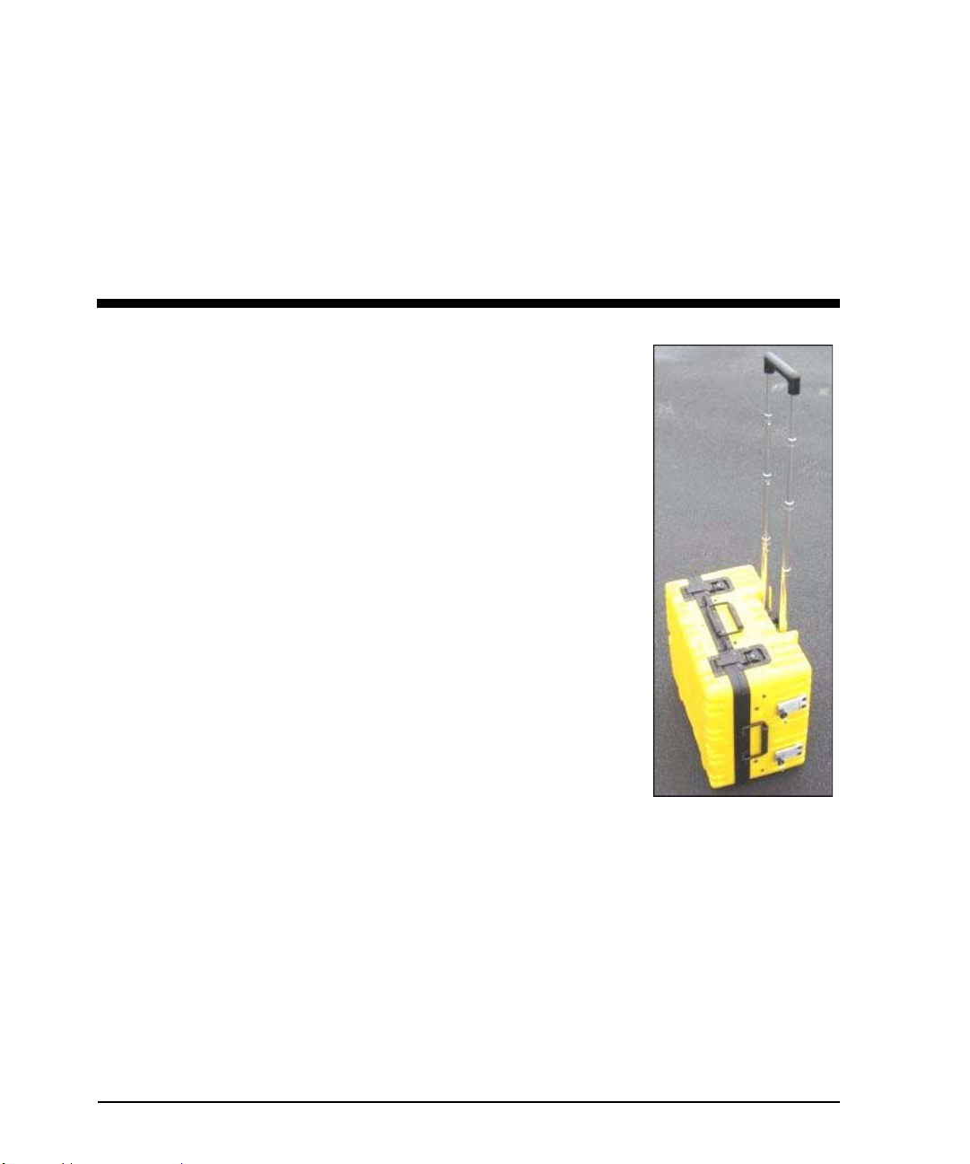
The MRX920ΤΜ unit is a rugged, compact, portable, easy-to-use, meter-reading unit for Neptune Radio Frequency
(RF) equipped water meters. It can be
securely placed in the passenger seat of
any vehicle using a standard seat belt
and can be powered by the vehicle
power supply receptacle.
The MRX920 unit provides the meterreading industry with many advantages
over current meter-reading methods:
• Suitable for any size utility
• Portable and easy to set up
• Significantly reduced man-hours
needed to collect readings
• Maximized meter reading success
rates
• Improved meter reading accuracy
• Access for meter that are “hard-to-read” and “dangerous-toread.”
• Increased safety and minimized liability exposure
MRX920/MTX950 User’s Manual 1-1
Page 17
Introduction
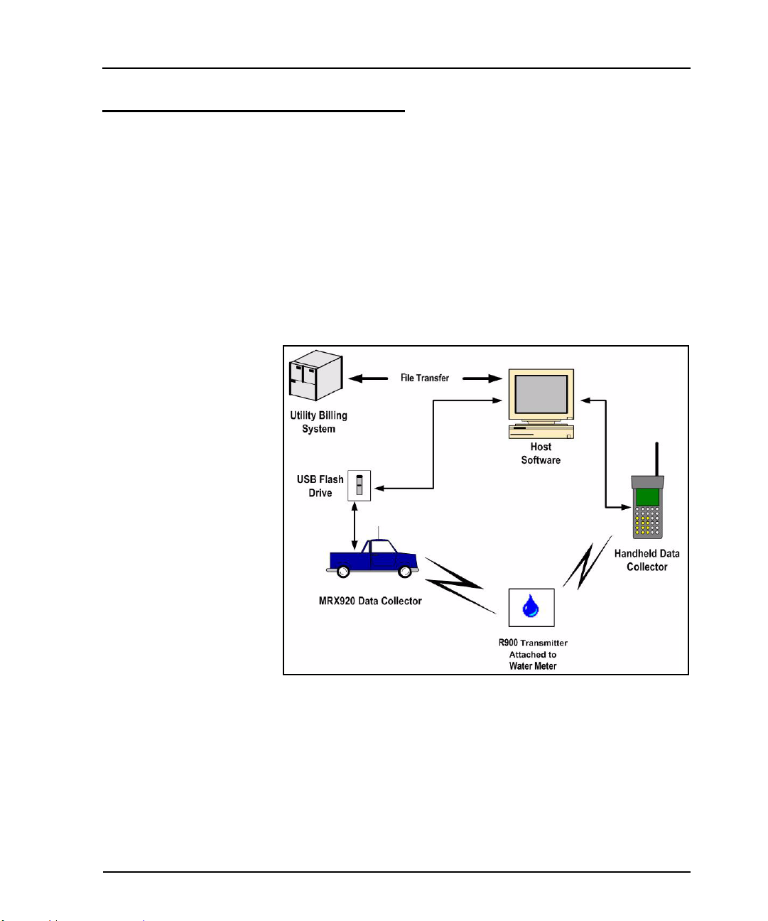
System Operations
Operators use Equinox-MRTM host software to make route assignments for meter readers. The routes to be read are obtained from
the utility billing system and placed on the USB flash drive for the
meter readers. Each meter reader inserts a USB flash drive into
the MRX920 unit and then drives through the routes assigned to be
read by collecting data broadcast by R900 Meter Interface Units
(MIUs). When complete, the meter readers return the USB flash
drives so the meter readings can be uploaded to the MTX950 host
software. The host software transfers the customer information to
the billing computer to generate customer bills. (See Figure 1.1.)
Figure 1.1 MRX920 Meter Reading Operations
1-2 MRX920/MTX950 User’s Manual
Page 18

About This Manual
Introduction
The MRX920/MTX950 User’s Manual describes the system and its
features. The manual also provides procedures on how to use the
MRX920 unit from setting up the unit and using its MTX950 software, to exiting and closing the unit.
This manual contains the following chapters:
Chapter Title Description
2 MRX920 Overview Provides an overview of the MRX920 unit
and software, including a description of
function keys, screens, and
MRX920 hardware.
3 Setting Up the MRX920
Unit
4 Using the MRX920 Unit Explains how the product works, proce-
5 Closing the MRX920 Unit Provides a procedure for closing the
Appendix A Specifications Provides a reference section containing
Appendix B Keyboard Provides a reference for the laptop key-
Appendix C Troubleshooting Provides diagnostics procedures for trou-
Describes hardware setup instructions,
power and antenna connection, and
instructions on how to turn on the laptop
computer. The chapter also includes information on how to adjust system settings
including keyboard backlighting, display
intensity, and the beeper settings.
dures for reading meters, reviewing
account information, reading missed
meters, and exiting the software.
MRX920 unit.
product specifications.
board and the LED activity and power indicators.
bleshooting MRX920 problems.
MRX920/MTX950 User’s Manual 1-3
Page 19
Introduction
Conventions Used in this Manual
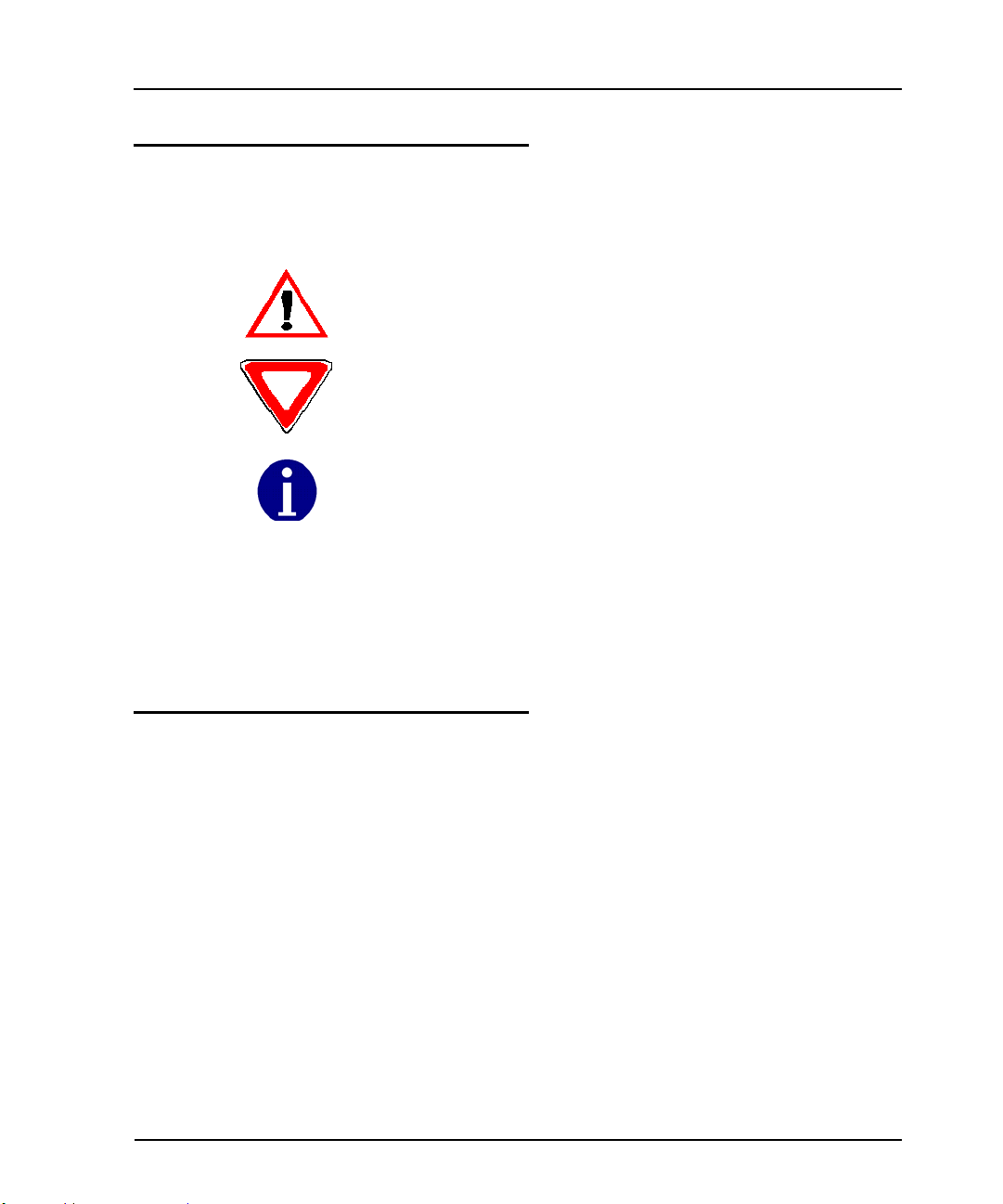
This manual uses the following icons and typographical conventions to identify special information.
The Warning icon identifies actions that can cause injury to the user or permanently damage the product.
The Caution icon identifies important information that is critical to ensuring
that data stored with the MRX920 unit is not lost.
The Note icon identifies information that clarifies a point within the text.
All small caps Refers to keys. Examples: ENTER, ALT, TAB
All bold initial caps Refers to field names, menus, buttons, and menu options. Example: Device field or
File menu.
+ between keys Refers to pressing the keys at the same time. Example:
ALT+B
Product Support within North America
Neptune offers various methods to obtain high-quality, responsive
technical support. However, before contacting Neptune, it is
important that you know the version number of the software that
your MRX920 unit uses. This information is useful to the support
technician who addresses the call.
To find the version number of MRX920 software, you must display
the System Check screen. For instructions on obtaining the version number of the MRX920 software, see “Performing Diagnostics,” on page C-3.
1-4 MRX920/MTX950 User’s Manual
Page 20

Contacting Technical Support
Within North America, Neptune technical support is available
Monday through Friday, 8:00 AM to 7:00 PM Eastern Standard
Time by telephone, email, or fax.
To contact technical support by phone, call 1 (800) 647-4832. You
will be directed to the appropriate team of specialists. These specialists are dedicated to you until the issue is resolved to your satisfaction. When placing a call, be prepared to give the following
information:
• The exact wording of any message that appears on the screen
of the MRX920 Unit.
• A description of what happened and what you were doing
when the problem occurred.
• A description of how you tried to solve the problem.
• Your company’s end user name.
You will be directed according to the options in Figure 1.2.
Introduction
Figure 1.2 Support Options
MRX920/MTX950 User’s Manual 1-5
Page 21

Introduction
To contact technical support by fax, send a description of your
problem to 1 (334) 283-7497. Please include on the fax cover sheet
the best time of day for a support specialist to contact you.
To contact technical support by e-mail, send your letter to the following address:
hhsupp@neptunetg.com
1-6 MRX920/MTX950 User’s Manual
Page 22

Chapter 2 MRX920 Overview
The MRX920 unit is a portable, mobile data collection device. It is
used in conjunction with internal MTX950 software and host
software to conduct automatic meter reading. The data collected
is then communicated to the utility’s billing system.
The MRX920 unit features the following:
• Durable carrying case designed for easy set-up and use in any
vehicle
• Fully waterproofed keyboard
• A touch screen display to allow for easy navigation and option
selection
• A beeper sound to indicate successful readings
• Exchange of route data between the MRX920 unit’s laptop and
host software
• Ability to read R900 radio transmitters
• Captured reads stored to the hard drive of the laptop
MRX920 Features
The MRX920 unit consists of a data collection receiver/processing
unit and laptop computer in a portable case designed for easy setup and use in meter reading (see Figure 2.1). The unit features
meter reading software designed for simplified route collection.
MRX920/MTX950 User’s Manual 2-1
Page 23
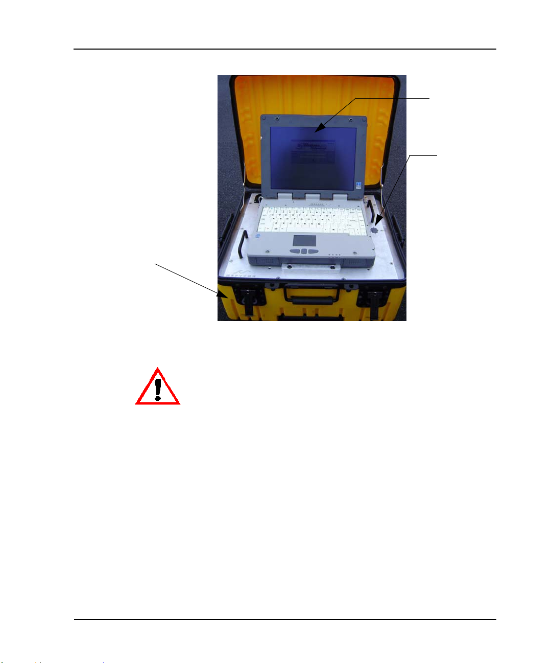
MRX920 Overview
Receiving/
Processing Unit
Laptop Computer
USB Flash Drive
inserts here
Figure 2.1 MRX920 Unit
Do not attempt to open the bottom of the MRX920 carrying case. Attempting to repair
or modify the unit on your own can result in personal injury or damage to the unit and
will void the warranty.
The Laptop
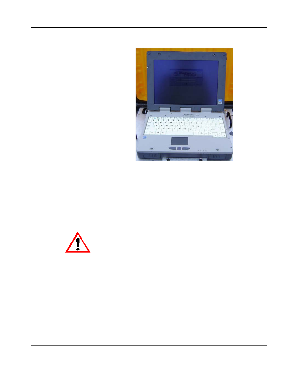
The laptop computer on the MRX920 unit, as shown in Figure 2.2,
is part of the overall MRX920 data collector. It communicates with
the receiver through a serial link using the software, which
decodes and records the collected readings by the receiver.
2-2 MRX920/MTX950 User’s Manual
Page 24
MRX920 Overview
Figure 2.2 Laptop
To protect the safety of the driver collecting readings, the laptop
computer provides an audible indicator option that can be turned
on or off as required. For more information, see “Beeper Settings,”
on page 4-3. When turned on, the unit only beeps when receiving
an MIU signal in the selected route. Other readings are silently
inserted into other routes.
To protect the driver’s safety, use the Beeper function on the MRX920 unit to monitor
meter reading.
The laptop computer retrieves meter readings from the receiver in
real-time, and stores them in nonvolatile memory. It checks meter
reading completeness against route files that are downloaded
from the host software. About one second after a reading is
received, the message area and progress bar update the reading
status of the route.
MRX920/MTX950 User’s Manual 2-3
Page 25
MRX920 Overview
USB Port
The USB port, shown in Figure 2.3, is located on the top plate of
the MRX920 laptop unit. Another USB port is located on the rear
of the laptop. You can use either slot for meter reading, but do not
use both USB ports at the same time.
Neptune recommends that you use only the USB port located on the top plate of the
MRX920 laptop for meter reading.
Figure 2.3 USB Port for USB Flash Drive
The MRX920 unit requires that you use only one USB port for the USB flash drive.
2-4 MRX920/MTX950 User’s Manual
Page 26
MRX920 Overview
Navigation
All MRX920 functions are performed in one of two ways:
•Using the
TAB key or the arrow
keys to move the focus to the appropriate button and pressing
ENTER.
• Using the provided stylus to touch the selections available on
the laptop display.
Always use the stylus provided with the laptop to touch the display. Substituting a
hard or sharp item can damage the display.
Figure 2.4 Navigating Within the Software
For example, Figure 2.4 shows the Route Import screen with
a route highlighted.
MRX920/MTX950 User’s Manual 2-5
Page 27

MRX920 Overview
Software
The software application runs on the laptop computer that is part
of the MRX920 unit. The purpose of the software is to log meter
readings from routes where R900s are installed. Messages from
MIUs outside of the route are identified as such and are discarded.
The software also provides a visual interface for the operator to
monitor route progress.
Although the software can start and stop the reading of message
data, it does not control the receive frequency or the decoding of
message data. Instead, the MRX920 unit contains a receiving and
processing unit that collects data only from R900s.
The file transfer between the host software and the MRX920 is
through the USB flash drive that store routes and accounts. The
file transfer between the host software and the utility company
billing system is in a file format specific to Neptune’s software
application.
MRX920 Display
Information about the screen display for MRX920 unit is
contained in “Laptop Specifications,” found on page A-1.
MRX920 Function Buttons
Each software screen contains different function buttons
pertaining to the specific information on that screen. Use the
following list to identify the different buttons and their specific
functions.
Welcome Screen
automatically launches the route import process
closes the software program
Route Import Screen
manually launches the route import process
2-6 MRX920/MTX950 User’s Manual
Page 28

stops the import route process
opens a dialog that allows the user to open a
specific database
closes the Route Import screen and returns to the
Welcome screen
Route Selection Screen
initiates the route reading process
temporarily pauses the reading process
closes the Route Selection screen and moves the user
to the Route Export screen
MRX920 Overview
Missed Reads Screen
opens a dialog that provides the user with various
details about the selected account, including the meter
number, MIU, the collection method, the account
name, coded notes, or skip codes
returns the user to the first account in the selected
route
Captured Reads Screen
opens a dialog that provides the user with various
details about the selected account, including the meter
number, the type of MIU, the collection method, the
account name, coded notes, or skip codes
MRX920/MTX950 User’s Manual 2-7
Page 29
MRX920 Overview
returns the user to the first account in the selected
route
Route Export Screen
launches the export of the loaded routes
closes the Route Selection screen and returns the user
to the Welcome screen
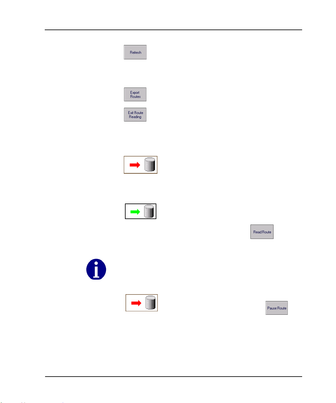
Reading Indicator
The Reading indicator, located on the title bar of
the software, shows the activity status of the
MRX920 unit. When the Route Selection screen is
first accessed, the Reading indicator resembles the
icon at the left with a red arrow, indicating that
there is currently no reading activity.
When the reading indicator displays a pulsing green
arrow, it indicates that the MRX920 unit is reading
and storing meter-reading data. To initiate route
reading, select the Read Route button.
If for any reason, the laptop is not receiving new data for a period longer than five
seconds, the Reading arrow stops pulsing.
Once you begin reading meters, the Read Route
button changes to the Pause Route
button. Selecting this button temporarily stops the
reading process, and the Reading indicator no
longer displays the pulsing arrow. When
reactivated, the MRX920 resumes reading.
2-8 MRX920/MTX950 User’s Manual
Page 30

MRX920 Overview
Message Area and Progress Bar
The message area on the software screens indicates the number
and percentage of meters on the route that were read successfully.
A graphical progress bar also shows the percentage of the route
that is complete. Before meter reading begins, no accounts are
reported as read, and the progress bar is blank.
While readings are captured, the Route Total progress bar shows
the percentage complete of the route selected on the Route
Selection screen. The Route Selection screen shows both the
selected Route Total as well as the readings Grand Total.
Information Area
The information area of a MRX920 screen displays the route or
addresses to be read. These following views are available:
• The route view includes the route number, number of MIUs to
be read, first address on the route, and percentage of the
route that was read.
• The account view provides a listing of the addresses and MIU
IDs to be read for a specific route. If you display account
detail, the information area displays information for the
selected account.
• A meter reading and loading indicator area with a graphic
progress bar and pulsing reading indicator.
• A message and information display area.
• An active function icon or reading indicator.
MRX920/MTX950 User’s Manual 2-9
Page 31

MRX920 Overview
Progress Bars
Message Area
Route Selection Screen
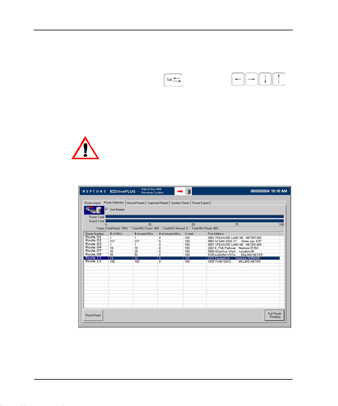
The Route Selection display screen illustrated in Figure 2.5 shows
loaded routes and the percentage of each route that has been
read. The screen includes the Reading indicator, an information
area with a list of routes, and a selection box that allows you to
turn the beeper on or off.
Reading Indicator
Information Area
Figure 2.5 Route Selection Screen
2-10 MRX920/MTX950 User’s Manual
Page 32

MRX920 Overview
Route Display Screens
There are two screens, the Missed Reads screen and the Captured
Reads screen (Figure 2.6), that provide information for a selected
route. Both of these screens have a message area for the selected
route with the total number of meters on the route, the number
that were read successfully, and the number that were missed.
The Missed Reads screen also has a graphical progress bar that
shows the percentage of the route that has been successfully read.
Message Areas
Graphic
Progress Bar
Figure 2.6 Missed Reads and Captured Reads Screens
MRX920/MTX950 User’s Manual 2-11
Page 33

MRX920 Overview
Viewing MIU Details
It is possible to view the details of a specific MIU from either the
Missed Reads or Captured Reads screen. The software allows you
to immediately identify the type of MIU by looking at the icons to
the left of each MIU in the information field.
— The blue MIU icon represents a R900 RF
transmitter.
The gray MIU icon with red circle around it and a
red diagonal line through it represents an inactive
meter. An “I” displays on the MIU Details screen in
the Account Status field.
Use the following procedure to access more detailed information
on a specific MIU.
1 Select the specific MIU by touching the screen with the stylus
or by using the or the keys.
2 Press the MIU Details button.
2-12 MRX920/MTX950 User’s Manual
Page 34

The MIU Details dialog (Figure 2.7) appears.
Figure 2.7 MIU Details Dialog
MRX920 Overview
MRX920 Unit
The MRX920 unit consists of an RF receiver that is made up
of the following 3 modules:
• RF (Radio Frequency) Front End
• Digital Multi-channel Receiver (DMR)
• CPU (based on a PC104 board)
RF Receiver
Radio Frequency (RF) Front End
The RF front end module receives the 910 - 920 MHz receiving
band from the antenna through the duplexer. The duplexer
functions as a translator, ensuring that the receiving band is
MRX920/MTX950 User’s Manual 2-13
Page 35

MRX920 Overview
passed from the antenna to the RF receiver. The RF front end
module then translates the RF spectrum from the 910 - 920 MHz
band down to a 41 MHz band.
Digital Multi-channel Receiver (DMR)
The DMR module receives and decodes the bands from the RF
front end module to determine if the signals are from an RF
module that uses the R900 protocol or other supported protocols.
Samples from up to 8 identified frequencies are processed to
obtain the data signals. The signals are compared to a profile, and
if there is a match, the signal is processed to extract and validate
the data within it. The extracted data is stored in local cache
memory.
The DMR processes 10 MHz of band with a full 128-channel
receiver, of which only 77 channels are available, and extracts
messages which are sent to the CPU. The DMR receives and
demodulates up to eight simultaneous R900 messages. The
MRX920 unit together with the MIU functions as a receiver that
works together as a spread spectrum system.
The MRX920 unit reads signals from R900 MIUs with a high rate of
success on the first pass. Inbound meter readings are collected
and stored into memory. The receiver processes the MIU signals,
and the application software ignores readings from MIU messages
received that are not currently loaded into the unit. Readings from
any MIU that are on one of the routes loaded into the MRX920 unit
will be processed and stored into memory.
The receiver filters out duplicates in order to keep the best or last
reading received. This optimizes memory storage space. Records
for each reading are stored in the receiver database to eliminate
duplicates and to keep track of reading data.
Central Processing Unit (CPU)
The Central Processing Unit (CPU), which temporarily stores
received data, is based on a PC104 board. It receives the messages
obtained from the band by the DMR module through the PC104
(ISA) bus. It then extracts the data and uses an RS-232 serial link
to transfer it to the laptop computer.
2-14 MRX920/MTX950 User’s Manual
Page 36

Power Supply
Antenna
MRX920 Overview
The MRX920 unit is powered by a 12V DC power supply. Refer to
Table A.5 located on page A-3 for the different operating voltages
and current levels.
When components require more than 12 volts, additional voltage
is generated using DC/DC converters; when components require
less than 12 volts, linear regulators are used.
To prevent excessive use of the battery, the MRX920 unit must not be operated if the
vehicle's engine is not running.
The power supply system has fuses and switches to control,
protect, and limit its operation.
The MRX920 antenna, used for filter and reception, is connected
to the RF receiver subsystem.
The antenna is made of a corrosion-free material that is tolerant to
ultra-violet exposure. It has a magnetic base and is capable of
staying in place at speeds of up to 70 miles per hour (m.p.h.).
While the antenna is designed to stay in place at speeds of up to 70 m.p.h.,
Neptune recommends operating the MRX920 at speeds not to exceed the legal limits.
For optimal performance, the MRX920 should not be operated at speeds greater than
30 m.p.h.
MRX920/MTX950 User’s Manual 2-15
Page 37

MRX920 Overview
Notes
2-16 MRX920/MTX950 User’s Manual
Page 38

Chapter 3 Setting Up the MRX920 Unit
This section provides basic instructions for setting up the MRX920
unit so it can be used to perform mobile meter reading and
exchange information with the host computer.
Neptune recommends that you insert the USB flash drive into the laptop after you place
the unit in the vehicle.
Placing the MRX920 Unit in the Vehicle
Follow this procedure to set up the MRX920 unit in the vehicle
passenger seat.
Never set up the MRX920 unit during a lightning storm or under excessively wet conditions.
1 Place the MRX920 unit in the passenger seat with the two
seatbelt retention loops facing the back of the seat.
2 Press the blue button on the safety pin, and pull the pin out of
the seatbelt retention loop. (See Figure 3.1 on Page 3-2.)
MRX920/MTX950 User’s Manual 3-1
Page 39

Setting Up the MRX920 Unit
Safety Pin
Blue Button
Seatbelt
Retention Loop
Figure 3.1 Removing the Safety Latch
3 Repeat Step 2 to remove the safety pin from the second
seatbelt retention loop.
4 Guide the seat belt through the seat belt retention loops, as
shown in Figure 3.2.
Figure 3.2 Placing Seatbelt in Retention Loop
3-2 MRX920/MTX950 User’s Manual
Page 40

Setting Up the MRX920 Unit
5 Replace the safety pins in the seatbelt retention loops, as
shown in Figure 3.3.
Safety Pin
Figure 3.3 Replacing the Safety Pin
6 Adjust the seat belt so that the unit is secure in the
passenger’s seat.
7 To further secure the unit, slide it against the back of the seat.
MRX920/MTX950 User’s Manual 3-3
Page 41

Setting Up the MRX920 Unit
Opening Carrying Case Cover
To set up the MRX920 unit in a vehicle, you must open the top
cover by opening the latches on the cover. See Figure 3.4.
Follow this procedure to open the latches on MRX920 unit, shown
in Figure 3.4, and open the carrying case top.
1 Lift the latch flap and turn it to the left.
The latch releases from the catch on the carrying case top.
Latches
Figure 3.4 Latches on MRX920 Carrying Case
2 Repeat step 1 for the other latch.
3 Open the cover until it locks in place. (See Figure 3.5.)
3-4 MRX920/MTX950 User’s Manual
Page 42

Setting Up the MRX920 Unit
Figure 3.5 Opening the Cover
4 To further secure the unit, slide it against the back of the seat
(see Figure 3.5).
If the unit interferes with your vision for the passenger window, rest the cover on top
of the laptop display to ensure maximum visibility.
Plugging in the Power Cable
Follow this procedure to connect the vehicle power supply power
cable to the MRX920 unit and plug it into the vehicle power supply
receptacle.
1 Start the vehicle.
MRX920/MTX950 User’s Manual 3-5
Page 43

Setting Up the MRX920 Unit
2 Insert the appropriate end of the vehicle power supply power
cable into the connector on the MRX920 unit, as illustrated in
Figure 3.6.
Vehicle Power Supply Cable
Figure 3.6 Vehicle Power Supply Power Cable
3 Plug the other end of the power cable into the vehicle power
supply receptacle as illustrated in Figure 3.7.
Vehicle Power Supply Receptacle
Figure 3.7 Vehicle Power Supply Power Cable Inserted In Car
3-6 MRX920/MTX950 User’s Manual
Page 44

Installing the Antenna
Setting Up the MRX920 Unit
The proper installation of the antenna cable is critical for the
optimal performance of the MRX920 Unit. If the cable is crimped,
the performance of the unit will degrade significantly.
There are several options for running the cable. The best method
depends on the type of vehicle being used. The most important
consideration when installing the antenna is for the cable to
remain intact.
To ensure proper installation of the antenna, complete the
following steps.
1 If the antenna cable is not plugged in, plug it into the socket
on the top right side of the drive-by unit next to the laptop
computer.
2 Place the magnetic base of the antenna in the center of the
roof approximately one foot behind the leading edge of the
roof.
Antenna Base
Figure 3.8 Antenna Installation
MRX920/MTX950 User’s Manual 3-7
Page 45

Setting Up the MRX920 Unit
3 Connect the antenna to the MRX920 unit, and hand-tighten the
connector by turning it clockwise until it is secured.
4 Route the antenna wire through the passenger window or
through the door. (See Figure 3.9.)
The cable runs
through the window,
which is the preferred
method.
Figure 3.9 Antenna Cable Through Window
Caution is necessary to ensure there is sufficient room for the cable and that
it does not get crimped.
A rear vent window on a mini-van can be another good location. Caution must also be taken when opening the door with
a cable running through the window. The cable can be pulled
out of the connector, again adversely affecting performance.
In some vehicles, there is enough room to run the cable through the doorframe of the
vehicle without crimping the cable. Also, the sound of the internal fan provides
auditory evidence that the power supply is working. Other vehicles do not always have
enough clearance (especially vehicles with rain gutters). Running the cable through a
rear door can be an option. You can also run the cable through a window.
3-8 MRX920/MTX950 User’s Manual
Page 46

5 Gently close the window, positioning the antenna cable so
there is no pressure on it.
Pressure on the antenna cable can cause damage!
Inserting the USB Flash Drive
Neptune recommends that you insert the USB flash drive into the
laptop after you place the MRX920 unit in the vehicle.
Follow this procedure to insert the USB flash drive containing the
routes you plan to read.
1 Remove the cover from the USB flash drive.
2 Remove the dust cover from the USB port.
Setting Up the MRX920 Unit
Neptune recommends that you use only the USB port located on the top plate of the
MRX920 laptop for meter reading.
MRX920/MTX950 User’s Manual 3-9
Page 47

Setting Up the MRX920 Unit
USB Flash Drive
USB Port
Figure 3.10 USB Port and Drive
3 Insert the USB flash drive into the port on the top plate of the
MRX920 unit.
Be careful not to force the USB flash drive into the slot. Forcing can causes
damage to the drive or to the metered data contained on the drive. If the drive
does not insert easily, rotate it 180
o
, and try to insert it again.
Turning the Unit On
Follow this procedure to turn on the MRX920 laptop and start the
MTX950 software.
1 With the laptop computer facing you, open the display.
2 Raise the display to a comfortable viewing position with the
keyboard accessible to you.
3-10 MRX920/MTX950 User’s Manual
Page 48

Setting Up the MRX920 Unit
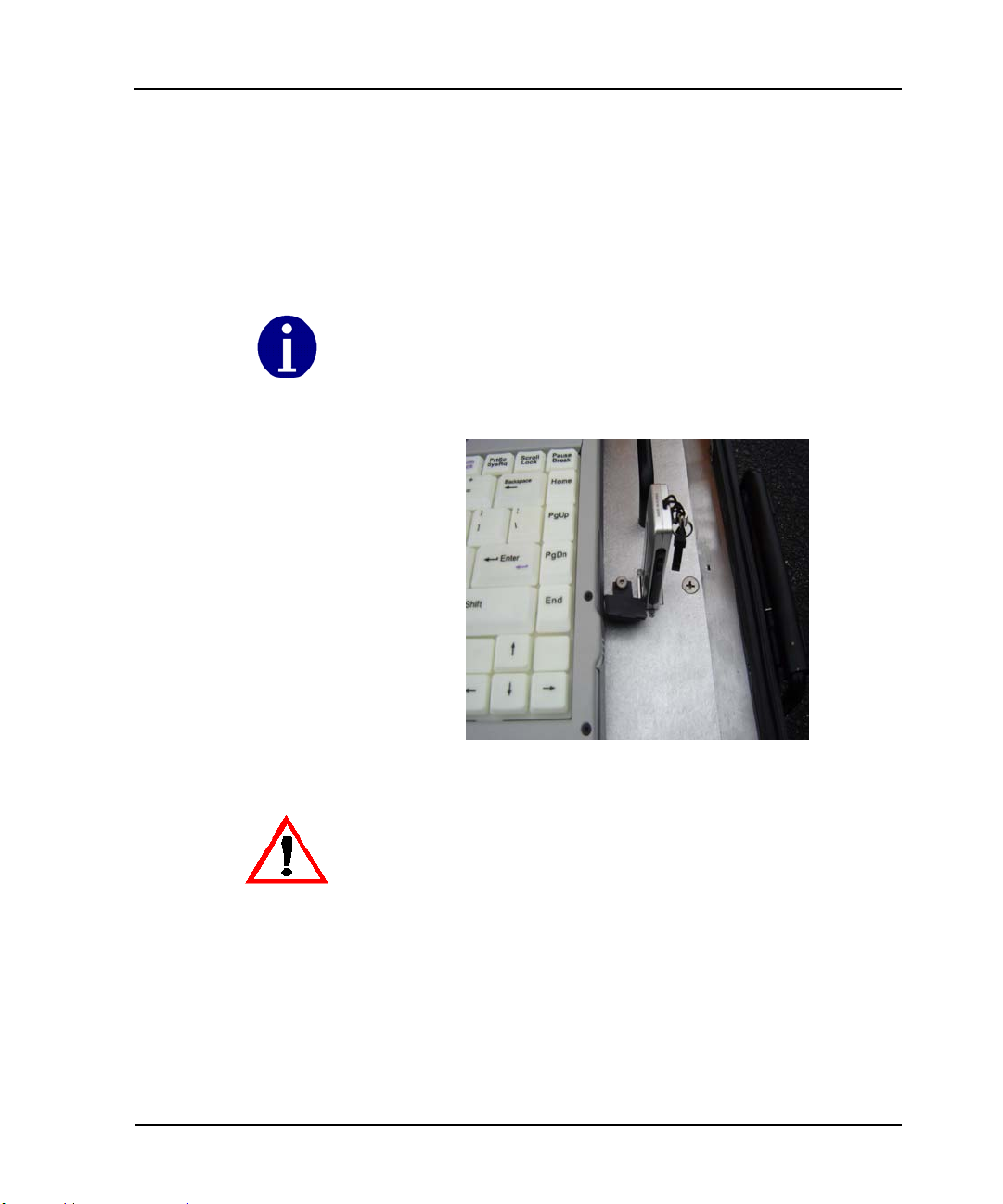
3 Press the power button located near the center of the
back edge of the laptop.
The power button is a soft raised button on the right side of the LED light indicators.
See Figure 3.11.
Tab
Alt
Ctrl
Touchpad
LED Activity Indicators
Figure 3.11 Laptop Keyboard
If the laptop fails to respond to the keys or to the stylus, reboot by pressing and holding
down Ctrl + Alt + Delete (Figure 3.11) for at least 10 seconds. Release the buttons to
restart the computer.
ON / OFF
LED Wireless/Modem Indicators
Arrow
Keys
Delete
For additional information on MRX920 self-diagnostics or
keyboard, see
• “Performing Diagnostics.” on page C-3.
• “Using the Keyboard.” on page B-1
MRX920/MTX950 User’s Manual 3-11
Page 49

Setting Up the MRX920 Unit
Starting the Software
Follow this procedure to start the software for your MRX920
laptop.
1 Double-click on the MRX920 icon on your Windows desktop.
The software automatically tries to import a route file. When
the import process is complete, the Route Selection screen
appears.
If the route data file is not found, a message displays. See “If No Route Data File is
Found.” on page C-5, for instructions.
2 Continue to “Using the MRX920 Unit.” on page 4-1, to begin
using your MRX920 unit.
Adjusting System Settings
This section describes several settings you can make to the
MRX920 unit to make it easier and more comfortable to use.
Contrast
The laptop XGA display is a transmissive color display designed to
minimize glare and maximize transmitted light from the backlight
so it has excellent readability in indirect light. The XGA display is
easy to read in vehicles. However, to increase or decrease the
brightness of the display, perform one of the following actions.
• Press
• Press
3-12 MRX920/MTX950 User’s Manual
FN + F6 to decrease LCD brightness.
FN + F7 to increase LCD brightness.
Page 50

Volume
Setting Up the MRX920 Unit
The volume for the beeper setting can also be controlled:
• Press
• Press
• Press
FN + F8—decreases the volume.
FN + F9—increases the volume.
FN + F10—toggles the volume mute on or off.
You can also adjust the volume with the Windows volume control
feature, which is located on the taskbar and looks like this .
Adjusting the volume using the function keys produces only a slight change with each
press. It may take several presses to increase or decrease the volume to the level that
you want.
MRX920/MTX950 User’s Manual 3-13
Page 51

Setting Up the MRX920 Unit
Notes:
3-14 MRX920/MTX950 User’s Manual
Page 52

Chapter 4 Using the MRX920 Unit
Using the MRX920 unit to collect readings begins with the host
software building a route file that is transferred to the MRX920
unit via the USB flash drive. The meter reader inserts the USB
flash drive in the MRX920 unit and begins automatic meter
reading by driving the vehicle through the route and collecting
readings. After the readings are complete, the meter reader
returns to the utility, shuts down the MRX920 unit, and removes
the USB flash drive to give it to the host computer operator. The
host computer operator transfers the data from the USB flash
drive to the host computer software and transfers the data to the
utility billing system computer.
Reading Meters
Because the MRX920 automatically reads meters, efficient use of
the system depends on two factors:
• the distance of the MRX920 unit from the MIU being read.
• the vehicle’s driving speed.
In a typical meter reading scenario, you drive your vehicle through
the routes listed on the route selection screen in any order. You
can position your vehicle at any route or starting address as
required by driving conditions and route distribution for the most
efficient data collection. The MRX920 unit reads and stores
readings regardless of the order of the routes displayed.
MRX920/MTX950 User’s Manual 4-1
Page 53

Using the MRX920 Unit
Figure 4.1 Route Display with Multiple Routes Being Read
When the MRX920 unit starts collecting data, the
Reading indicator changes to display a pulsing green
arrow. This icon continues to pulse as long as read
data is received within a period of five seconds.
In normal use, you focus on driving and listening for beeps on the selected
route. You DO NOT need to look at the screen on the MRX920 unit while you
are driving. The MRX920 unit automatically receives and stores any readings
within range for any MIU IDs that are loaded on the laptop.
4-2 MRX920/MTX950 User’s Manual
Page 54

Beeper Settings
Using the MRX920 Unit
A beeper is available in the MRX920 unit to emit a beep tone for
every account that is read and stored in the MTX950 software.
This helps to monitor the meter reading without having to look at
the laptop display. This also offers a safe way to monitor reading
progress while driving a route.
The beeper only sounds while the MRX920 is performing readings
and stops when all readings are completed. You can turn the
beeper function on or off while the unit is performing readings.
The default setting in the MRX920 is for the beep tone to be turned
off.
Turning the Beeper On or Off
Follow this procedure to switch the MRX920 beeper on or off.
1 Access the Route Selection screen.
At the top of the screen, there is a Use Beeper field with a
check box, as shown in Figure 4.2.
Beeps are only heard when readings are posted for MIUs in the selected route.
MRX920/MTX950 User’s Manual 4-3
Page 55

Using the MRX920 Unit
Beeper check box
Figure 4.2 Use Beeper Field
2 Select the box using the stylus.
A check in the box indicates the beeper is on. An empty box
indicates the beeper is off.
4-4 MRX920/MTX950 User’s Manual
Page 56

Selecting Routes
Using the MRX920 Unit
This is an optional step if you want to review selected routes to
determine a good starting point for reading.
1 Access the Route Selection screen, shown in Figure 4.3, by
pressing the Route Selection tab.
Figure 4.3 Route Selection Screen
2 Highlight the route to be viewed.
3 Select the Missed Reads tab to display the Missed Reads
screen.
All accounts that are unread or missed during the reading
process are displayed on the Missed Reads screen as shown
in Figure 4.4.
MRX920/MTX950 User’s Manual 4-5
Page 57

Using the MRX920 Unit
Figure 4.4 Missed Reads Screen
The Missed Read screen appears showing the accounts in the
route, with the first address in the route on the first line.
4 If necessary, select another address for your starting point.
5 To get detailed information on an account, select that account
and press the MIU Details button.
4-6 MRX920/MTX950 User’s Manual
Page 58

Using the MRX920 Unit
The MIU Details dialog, shown in Figure 4.5, appears.
Figure 4.5 MIU Details Dialog
6 Go to the procedure “Starting Meter Reads,” on page 4-10 to
begin reading the route.
Detail Settings
When viewing route information in the software, you can view the
details of a specific account. Account details consist of the
following:
• Parent Route • Account Number
• Meter Number • Account Address
• Account Name • Collection Method
•MIU-ID •MIU Type
• Channel • Wakeup Tone
MRX920/MTX950 User’s Manual 4-7
Page 59

Using the MRX920 Unit
Viewing Account Detail
Follow this procedure to view account details for selected
accounts.
1 From the Route Selection screen, highlight the route
containing the account you want to view, as shown in
Figure 4.6.
Figure 4.6 Route Selection Screen with Route Highlighted
4-8 MRX920/MTX950 User’s Manual
Page 60

Using the MRX920 Unit
2 Go to either the Missed Reads or Captured Reads screen,
depending on whether or not the account has already been
read. See Figure 4.7.
Figure 4.7 Captured Read Screen with Account Highlighted
3 Highlight the specific account.
4 Press the MIU Details button.
The MIU Details dialog appears with the details of the
selected account. See Figure 4.5.
5 To close the MIU Details dialog, select OK.
MRX920/MTX950 User’s Manual 4-9
Page 61

Using the MRX920 Unit
Collecting Readings
For the meter reader’s safety, the MRX920 unit is designed so that there is no
requirement to use the laptop display and keyboard while driving. To verify that the
unit is reading properly, use the beeper option to monitor readings.
On occasion, it could be necessary for the driver to stop and view
routes and display account detail. A meter reader can easily
suspend meter reading and restart it before continuing on a route.
See “Pausing and Restarting Meter Reading,” on page 4-19.
Starting Meter Reads
Follow this procedure to begin collecting meter readings after you
have positioned your vehicle at the starting address and started up
the MRX920 laptop computer.
To read meters, the plug-in power cord on the MRX920 unit must be connected to the
vehicle power supply receptacle. Make sure the red LED is lit on the power cable.
1 From the welcome screen, press the Start button
and the routes on the USB flash drive automatically load into
the software.
2 Highlight the route where you begin reading.
The Route Selection screen automatically appears.
3 Click the route you want to see on the Missed Reads and
Captured Reads screens.
4-10 MRX920/MTX950 User’s Manual
Page 62

Using the MRX920 Unit
4 Press the Read Route button.
Missed Reads Screen
Figure 4.8 Reading a Route
The Reading indicator turns on and pulses to
indicate that reading is in progress. Addresses
and routes that are successfully read are listed
on the Captured Reads screen. Any remaining
unread or missed routes are listed on the
Missed Reads screen. The Reading icon
continues to pulse as long as read data is
received within a period of five seconds.
If there are any inactive meters on this route, they are listed on the Captured Reads
screen, represented by the icon ––a gray meter enclosed in a red circle with a
line through it. Refer to “Viewing MIU Details,” on page 2-12.
5 Start driving your vehicle by each address along the route at
the posted speed limits.
While the antenna is designed to stay in place at speeds of up to 70 m.p.h.,
Neptune recommends operating the MRX920 at speeds not to exceed the legal limits.
For optimal performance, the MRX920 should not be operated at speeds greater than
30 m.p.h.
MRX920/MTX950 User’s Manual 4-11
Page 63

Using the MRX920 Unit
Total Read
Use the Beeper function on the MRX920 unit to monitor meter reading while
driving. Use of the laptop display or keyboard can compromise driver safety.
See “Turning the Beeper On or Off,” on page 4-3.
6 If the message area at the top of the Captured Reads screen
indicates that all accounts on the route have been read (as
shown in Figure 4.9), select the next route to be read.
Figure 4.9 Route With All Reads Completed
The Reading indicator on the software screen
pulses as you continue driving each route until
all of the routes have been read. When reading
is completed, check the Missed Reads screen to
see if there are any missed accounts.
4-12 MRX920/MTX950 User’s Manual
Page 64

7 Choose from the following:
• To pause the MRX920 meter reading before all routes
have been read, see “Pausing and Restarting Meter Reading,” on page 4-19.
• To reread missed meters, see “Using Coded Notes or Skip
Codes,” on page 4-16.
• To end meter reading and upload the read data to the Host
software, see “Exiting the Software,” on page 4-21.
Navigation on the Route Display Screen
Before you complete readings for the MRX920 routes, you can
move between routes on the route display screen to select the
route information you want to view. This also gives you access to
route details and individual account information.
You can move between the routes whether or not the MRX920 is
actively reading meters.
1 Touch the screen with the stylus to select the desired route.
Using the MRX920 Unit
2 Press to move backward through the route, or to
move forward through the route.
Viewing Routes
Follow this procedure to select routes to display route reading
progress and route detail. You can perform this procedure
whether or not routes are actively being read.
1 Press the Route Selection tab to access the Route Selection
MRX920/MTX950 User’s Manual 4-13
Page 65

Using the MRX920 Unit
screen, shown in Figure 4.10.
Figure 4.10 Route Selection Screen
2 Highlight the specific route you want to view.
The top graphical progress bar displays the percentage of the
route that is complete.
3 Select the Missed Reads or Captured Reads screen. (See
Figure 4.11)
Both screens display the individual accounts within the
selected route. The message area at the top of the screen
4-14 MRX920/MTX950 User’s Manual
Page 66

Using the MRX920 Unit
display the route number, total MIUs, total MIUs read, and
total MIUs missed.
Message Area
Figure 4.11 Captured Reads Screen Message Area
Identifying Missed Accounts
Occasionally, because of driving speed, RF interference, or
problems with the MIUs, it is possible to miss a meter reading.
Usually, you can tell if meters are missed because the route does
not progress to a read status of 100%. To view the missed
accounts:
1 From the Route Selection screen, highlight the route
containing the missed reads.
2 Press the Missed Reads tab to display the Missed Reads
screen.
MRX920/MTX950 User’s Manual 4-15
Page 67

Using the MRX920 Unit
Refer to the following section, "Viewing Account Details" for
specific details of a missed account.
Viewing Account Details
Before reading begins, the Route Selection screen displays zeros
for all routes in the # of read MIUs field. Once reading is
initiated, the captured reads for each route are recorded in this
field.
After meter reading is completed, only the missed or unread
accounts remain on the Missed Reads screen. The meter reader
then knows which addresses to reread.
If for any reason the MRX920 is not able to read missed MIUs on
the second attempt, the meter reader can select specific accounts
by using the MIU Details dialog to display more information for
the account.
Using Coded Notes or Skip Codes
All missed accounts are listed in the information area of the
screen.
You can use the MIU Details screen to record trouble that you are
having with the reading. Or if you choose to skip the reading, you
can record the reason. However, you cannot have an automatic
reading with a skip code. The skip codes means that you are
skipping the reading.
When viewing details for an account, only two of the three notes fields can display.
There is always the reading code, and either a trouble code or a skip code.
Entering a Trouble Code
To enter a trouble code, complete the following steps.
1On the MIU Details screen, tab to the Coded Notes field.
2 Choose one of the following options:
4-16 MRX920/MTX950 User’s Manual
Page 68

Using the MRX920 Unit
• If you already know the trouble code, type it in the Coded
Notes field.
• If you do not know the code, tab to the TroubleCode
Description field, and select the reason code from the
drop-down selection list.
3 Press Save to record the reason for the trouble.
Entering a Skip Code
To enter a code for why you skipped a reading, complete the
following steps.
EZRouteMAPS customers should NOT use skip codes.
1On the MIU Details screen, tab to the SkipNotes field.
2 Choose one of the following options:
• If you already know the skip code, type it in the
SkipNotes field.
• If you do not know the skip code, tab to the SkipCode
Description field, and select the reason code from the
drop-down selection list.
3 Press Save to record the reason for skipping the reading.
Moving From One Account to the Next
Before completing readings for the addresses in a route, you can
move between accounts to select the account to display.
1 Touch the screen with the stylus to select the desired account.
2 Press to move backward through the route or to
move forward through the route.
MRX920/MTX950 User’s Manual 4-17
Page 69

Using the MRX920 Unit
Displaying Account Detail
Follow this procedure to view route detail for selected routes.
1 From the Route Selection screen, highlight the appropriate
account.
2 Select either the Missed Reads screen or the Captured
Reads screen, depending on whether or not the account has
been read.
3 Highlight a specific account.
4 Press the MIU Details button.
The MIU Details dialog (Figure 4.12) appears.
Figure 4.12 MIU Details dialog
The collection method on the Account Detail screen is unlicensed
radio frequency (R900 MIUs). Usually route numbers are derived
from the route numbers assigned at the time of previous meter
reading routes, such as handheld meter reader routes.
4-18 MRX920/MTX950 User’s Manual
Page 70

In addition, the fields for Coded Notes or Skip Codes allow you
to record information about this account. See “Using Coded Notes
or Skip Codes,” on page 4-16.
Reading Missed Accounts
The procedure for reading missed accounts is similar to the
procedure used on the initial reading. To assist in reading missed
accounts, you need to view route and account details to locate the
exact starting point for reading. It is also helpful to drive slower
and get as close as possible to the missed meters to improve
chances of receiving read data.
To identify a missed meter, select a route from the Route Selection
screen that shows a read status of less than 100% in the progress
bar at the top of the screen. Once selected, missed accounts from
that route are shown on the Missed Reads screen.
If necessary, use the MIU Detail button for the missed account
and determine if there are any problems with the account that
prevent a successful reading. Note the address of any accounts for
subsequent reading and reporting.
Using the MRX920 Unit
To read a missed meter, drive to the first unread account address
on the route. Read the remaining accounts on the route.
If you do not succeed in reading an account after a second
attempt, the account remains with a status of “unread.” The utility
can initiate follow-up action to investigate the source of the
reading problem.
Pausing and Restarting Meter Reading
Follow this procedure to stop and then restart data collection
using the MRX920 unit. This is useful if you want to review the
route reading status of a route or individual account or if you need
to look up the starting address for a route to be read.
1 While the Reading indicator is pulsing, press the Pause
Route button.
MRX920/MTX950 User’s Manual 4-19
Page 71

Using the MRX920 Unit
The Reading indicator stops displaying the
pulsing green arrow. When you press the
Pause Route button, the red arrow displays.
2 To review account information before restarting, select either
the Missed Reads or Captured Reads screen, depending on
whether or not the account has already been read.
3 Select an account and press the MIU Details
button.
4 To resume automatic reading, press the Read Route
button.
Reading continues and the Reading indicator
switches back to a status of “Reading”.
4-20 MRX920/MTX950 User’s Manual
Page 72

Creating an Export File
Exiting the Software
Using the MRX920 Unit
After you have completed reading all of your routes, you need to
create an export file for your utility to upload the read data to the
host software.
When all routes have been read, use the following procedure to
create an export file:
1 Press the Route Export tab to display the Route Export
screen.
2 Press the Export Routes button to store the routes
on the USB flash drive.
There are three screens, Route Import, Route Selection, and
Route Export, that display the Exit Route Reading button. On the
Route Import and Route Export screens, when you press this
button you return to the Welcome screen. When you press this
button from the Route Selection screen, the Route Export screen
displays. Complete the following procedure to exit the software,
then proceed to the procedure to turn off the laptop.
From the Route Import and Route Export Screens
1 Press the Exit Route Reading button.
The Welcome screen displays.
2 Press the Exit Program button.
the software closes.
It is now safe to turn off your computer. Proceed to
"Turning off the Laptop".
MRX920/MTX950 User’s Manual 4-21
Page 73

Using the MRX920 Unit
From the Route Selection Screen
1 Press the Exit Route Reading button.
The Route Export screen displays.
2 On the Route Export screen, press the Exit Route Reading
The Welcome screen displays.
3 Press the Exit Program button.
The software closes.
It is now safe to turn off your computer. Proceed to
"Turning off the Laptop".
Turning off the Laptop
button again.
1 From the Start menu, click Shut Down.
2 From the Shut Down Windows screen select Shut Down.
3 Click OK.
4 You can now safely remove the USB flash drive. (Refer to
“Removing the USB Flash Drive,” on page 4-23.)
Improperly removing the USB flash drive while the laptop is ON can cause data
corruption on the USB flash drive. Refer to the following section for procedures to
safely remove the USB flash drive while the PC is on.
5 Remove the power cable from the vehicle power supply
receptacle.
6 Drive back to your utility to return the USB flash drive
containing the read data so it can be uploaded to the host
software.
4-22 MRX920/MTX950 User’s Manual
Page 74

Removing the USB Flash Drive
Follow this procedure to safely remove the USB flash drive from
the laptop while it is operating.
Improperly removing the USB flash drive while the laptop is ON can cause
data corruption on the USB flash drive.
1 Click the USB flash drive icon located in the lower right
corner of the Windows task bar.
The USB flash drive properties dialog appears.
2 Select the Socket Status tab.
3 Select the USB flash drive from the list provided.
As shown in Figure 2.3 on Page 2-4, the list provided shows
one socket as being empty. (Refer to “USB Port,” on page 2-4.)
Using the MRX920 Unit
4 Click OK.
A dialog displays telling you that you can now remove the
USB flash drive.
5 Remove the USB flash drive from the port on the back of the
laptop.
MRX920/MTX950 User’s Manual 4-23
Page 75

Using the MRX920 Unit
Notes
4-24 MRX920/MTX950 User’s Manual
Page 76

Chapter 5 Closing the MRX920 Unit
Preparing to Remove the MRX920 Unit
Follow this procedure to close up the MRX920 unit, and
prepare it for removal from the vehicle.
1 With the laptop computer turned off, close the laptop display.
2 Remove the power cable from the vehicle power supply
receptacle.
3 Remove the antenna from the vehicle roof.
4 Remove the antenna cable from the MRX920 unit.
Figure 5.1 Laptop Prepared for Closing
MRX920/MTX950 User’s Manual 5-1
Page 77

Closing the MRX920 Unit
5 Remove the vehicle seat belt from the seat belt retention
loops on the MRX920 carrying case.
6 Close the cover on the MRX920 unit and secure it by closing
the latches on the unit.
Figure 5.2 Cover Closed on the MRX920 Unit
5-2 MRX920/MTX950 User’s Manual
Page 78

Appendix A Specifications
Electrical Specifications
Power Consumption 9A maximum
Power Supply 12V DC via plug-in power cord
Laptop Specifications
System Type
Keyboard
Display
Table A.1 Electrical Specifications
Table A.2 PC Specifications
Windows Based
1.7 GHz Intel® Pentium 4 Processor with 512 L2 Cache
256 to 1024 MB DDR SDRAM
12 Function keys
Fully waterproofed design
Built-in, solid state mouse
Embedded numeric keypad
7 programmable function keys
12.1” TFT XGA Outdoor transmissive ColorVue display
with Touchscreen.
VGA Graphics Controller with 2MB VRAM.
User adjustable contrast and intensity
Light sensor which adjusts screen intensity per
ambient light
Shock/scratch resistant anti-glare plate
Operating System Windows 2000
MRX920/MTX950 User’s Manual A-1
Page 79

Appendix A Specifications
Environmental Conditions
Operating Temperature 32° to 122°F (0° to 50°C)
Storage Temperature -40° to 185°F (-40° to 85°C)
Operating Humidity 5% to 95% non-condensing relative humidity
Dimensions and Weight
Dimensions Refer to Figure A.1, measurement in inches.
Weight 48.0 lbs
Table A.3 Environmental Conditions
Table A.4 Dimensions and Weight
18.00"
15.00"
12.00"
Figure A.1 MRX920 Unit Dimensions
A-2 MRX920/MTX950 User’s Manual
Page 80

Power Supply
Appendix A Specifications
Table A.5 Operating Voltage and Current
Component
MRX920- Laptop Computer turned
ON
Nominal
Operating Voltage
12V 3 to 6A 9A
Nominal
Operating Current
Maximum
Operating Current
MRX920/MTX950 User’s Manual A-3
Page 81

Appendix A Specifications
Notes:
A-4 MRX920/MTX950 User’s Manual
Page 82

Appendix B Keyboard
Using the Keyboard
The MRX920 laptop has a US 89-key international keyboard. There
are twelve function keys, F1-F12, and an embedded numeric
keypad. Situated below the keyboard are the mouse keys and
cursor control directional keys. See Figure 3.11on Page 3-11.
Numeric Keypad
The numeric keypad is embedded in the keyboard area. The
embedded keypad emulates the numeric keypad typically found
on a full-size keyboard. It is arranged like a calculator for
applications that require you to key many numbers or for use with
the Calculator in the standard Windows Accessories.
Figure 1.6 Numeric Keyboard
MRX920/MTX950 User’s Manual B-1
Page 83

Appendix B: Keyboard
Touchpad
The touchpad is a pointing device that provides all the features of
a two-button mouse. Its primary function is to move the cursor
around the screen.
Figure 1.7 Touchpad
Using Your Touchpad
Clicking
First, place your fingers on the keyboard in the normal typing
position. The touchpad is easily accessible by moving either your
left or right thumb off the space bar and on to the touchpad.
Gently move your thumb across the touchpad in the direction you
want the cursor to move. The pad detects the change in pressure
and moves the cursor in the corresponding direction.
The touchpad on your MRX920 laptop is electrically sensitive to finger touch. It will not
respond if touched by anything other than your fingers, such as a stylus or pencil.
With the touchpad there is another method of making selections
in a MTX950 software program. It is called double-tapping. This
function corresponds to double-clicking with a mouse. Once the
cursor has been moved to the object you want to select, lightly
double-tap the pressure sensitive touchpad. This double-tapping
on the touchpad will select the desired item and prompt the
software to perform the related operation.
The left and right buttons located directly below the touchpad are
the same in function as those on a two-buttoned mouse. Clicking
these buttons makes selections, drags objects, or performs a
B-2 MRX920/MTX950 User’s Manual
Page 84

Appendix B: Keyboard
variety of other functions depending on the software. To select an
object, first move the pointer over the object you want to select,
and then press the left button one time. The functions of these
buttons are software specific.
Double-clicking
Double-clicking is a common technique for selecting objects or
launching programs from icons. Once you have moved the pointer
over the object you wish to select, rapidly press the left button
two times. This action is commonly referred to as “doubleclicking” an object.
Dragging
Move the pointer to the desired location then press down the left
button. While still holding down the left button, move the pointer
to the desired location. Release the button.
Move the pointer to the desired location. Tap the touchpad twice
quickly as if you were double-clicking, however do not remove
your finger after the second tap. Move the cursor to the desired
location. Lift your finger to finish dragging.
Adjust the touchpad settings by selecting Settings/Control Panel/
Mouse/Buttons. These settings allow you to change the
orientation of the touchpad from right-handed to left-handed, and
fine-tune the pointer movement and timing of clicks.
Touchpad Precautions
If not properly cared for the touchpad can be easily damaged.
Please take note of the following precautions.
Do not rest heavy objects on the touchpad or the touchpad buttons.
MRX920/MTX950 User’s Manual B-3
Page 85

Appendix B: Keyboard
LED Activity Indicators
The activity indicators, located above the keyboard, light up when
a particular function of the computer is active. Each indicator is
marked with a corresponding symbol and is visible when the lid is
open or closed. LED numbers are from left to right.
Figure B.8 LED Activity Indicators
Table B.1 LED Activity Indicators
Icon Function LED Description
Mini PCI Lit Power is on to the Mini-PCI
Wireless LAN
Bluetooth Lit Bluetooth Power is on
Lit The hard disk drive is being
Disk Status (hardware)
Not Lit The hard disk drive is not being
Media Drive Bay Lit The computer is accessing the CD-
Number Lock Lit The keyboard is in Num Lock
Caps Lock Lit The keyboard is in Caps Lock mode
Scroll Lock Lit The keyboard is in Scroll Lock
accessed
access
ROM, the DVD-ROM, or the Floppy
drive.
mode.
mode
B-4 MRX920/MTX950 User’s Manual
Page 86

LED Power / Wireless Modem Indicators
The case front LEDs indicate external power, unit ON/OFF,
battery status, and wireless modem ON/OFF. The indicators
remain active and viewable even when the LCD panel is closed.
Figure B.9 LED Power Indicators
Table B.2 LED Power Indicators
Icon Function LED Description
External Power
Appendix B: Keyboard
Green External power is connected to the
unit.
LED Off External power is not connected to
the unit.
Green Power is ON
Power
Battery
Wireless Modem
Flashing
Green
Green Battery charging
Flashing
Green
LED Off No battery or battery fully charged
Green Wireless modem is ON
Flashing
Green
LED Off Wireless modem is OFF
Low Battery
The hard disk drive is being
accessed
(always OFF without external
power connected to the unit)
Message waiting
MRX920/MTX950 User’s Manual B-5
Page 87

Appendix B: Keyboard
Notes:
B-6 MRX920/MTX950 User’s Manual
Page 88

Appendix C Troubleshooting
Troubleshooting Problems
Use the following table to help identify possible solutions to problems that could occur.
Problem Probable Cause Things to Check
No Power to the unit.
Table A.10 Troubleshooting Table
Loose connection at vehicle power supply receptacle.
Make sure you can hear the
Loose connection between
MRX920 unit and power
cable.
Bad power cable
unit’s internal fans.
Check the continuity of the
cable with ohm meter.
Power is applied, the
MTX950 software executes, but no route data is
available.
Dead battery or fuse in utility vehicle.
No power to vehicle power
supply receptacle.
USB flash drive not inserted
Incompatible data on USB
flash drive. See “Performing Diagnostics,” on page
C-3.
Check the electrical status
of the utility vehicle.
Insert lighter and check to
see if it heats up.
Make sure USB flash drive
has been inserted.
Select Self-Diagnostics tab
to verify that the data on
the USB flash drive is com-
patible.
MRX920/MTX950 User’s Manual C-1
Page 89

Appendix C Troubleshooting
Table A.10 Troubleshooting Table
Problem Probable Cause Things to Check
Power is on but the screen
is blank or unreadable.
The software appears to be
working but does not collect data.
Intensity settings too high
or too low
Power to PC not on
Antenna not connected
properly or not installed
Broken antenna cable
Check Intensity settings.
Make sure I-O (On/Off) key
has been pressed.
Check antenna connection.
C-2 MRX920/MTX950 User’s Manual
Page 90

Performing Diagnostics
The software performs diagnostics when you access the System
Check screen. This allows you to check the status of the system
components.
Displaying the Software Self Diagnostics
Follow this procedure to display the software System Check
screen.
1 Press the Start button from the software Welcome
screen.
The Route Import screen (Figure C.1) appears.
Appendix C Troubleshooting
Figure A.1 Route Import Screen
MRX920/MTX950 User’s Manual C-3
Page 91

Appendix C Troubleshooting
2 Press the System Check tab to display the System Check
screen, as shown in Figure C.1.
Figure A.1 System Check Screen
The software System Check screen contains the following
fields for meter reading components:
• Meter Reader—name of the meter reader as obtained
from USB flash drive files
• HD Space—verification that the laptop has sufficient hard
disk space
• USB flash drive space—the amount of available free
space on the memory card
• Collection Method—identification of the meter reading
data collection method being used
• DBDC API Version—software version installed on the
MRX920 unit
• DBDC Firm Ware Version—Firm Ware version on the
DMR board
C-4 MRX920/MTX950 User’s Manual
Page 92

• Software Version—identification of the version number of
• Temperature—notifies the user whether or not the tem-
3 To exit the software System Check screen, select another
screen from the tabs.
Importing Route Data
If No Route Data File is Found
If the USB flash drive is not inserted in the USB port when the
software is started, the following screen appears with a warning
message indicating that an import file was not found (see Figure
C.1).
Appendix C Troubleshooting
the software
perature of the unit is okay for operation.
Figure A.1 Error Message on Start Up
MRX920/MTX950 User’s Manual C-5
Page 93

Appendix C Troubleshooting
This error can result from two possible situations:
• The MRX920 laptop does not recognize the USB flash drive.
• There is no roadmaps.imp file found on the USB flash drive.
Correcting the Import Error
To correct this error and load the import file, do one of the
following:
1 Press the to close the dialog, and press the
EXIT PROGRAM
button to exit the software.
2Go to My Computer or Windows Explorer to verify that the
USB flash drive is recognized by the laptop.
If the USB flash drive is recognized, My Computer or Windows Explorer will show a drive letter for the USB flash drive,
usually G:.
If the USB flash drive is not recognized by the laptop, try rebooting your laptop.
3 Click G: (or the appropriate drive letter) to verify that the
roadmaps.imp file is located on the USB flash drive.
4If the roadmaps.imp file is found, shut down the laptop as
described in “Turning off the Laptop,” on Page 4-22.
5 Remove the flash drive.
6 Reboot the laptop and insert the USB flash drive. Then repeat
steps 2 to 4 to verify that USB flash drive is recognized by the
laptop and the import file is found on the USB flash drive.
If the roadmaps.imp file is not found, go back to the host computer and be sure the file
is loaded on the USB flash drive. Once the file is loaded on the USB flash drive, restart
the laptop.
C-6 MRX920/MTX950 User’s Manual
Page 94

Glossary
central processing unit Often abbreviated as CPU, it is the brain of the computer. Sometimes referred
to as the processor or central processor, the CPU is where most calculations
take place. In terms of computing power, the CPU is the most important
element of a computer system.
default setting A computer term that is similar in meaning to factory setting. The default
setting is one that the MTX950 software automatically applies to an item. For
example, the default setting for Beeper On/Off mode is Beeper Off. The
beeper is always off unless the meter reader changes the beeper setting.
direction keys Special keys on MRX920 laptop keyboard that allow you to move up or down
a list of items. The direction keys, the Up (F5) and Down (F4) keys are
indicated by arrow key icons on the MRX920 display.
display The top part of the laptop computer where selections and information about
routes and accounts are shown.
download The process of sending readings and route information from the Host
Computer to the USB flash drive used for readings.
function key Special key on the MRX920 keyboard that allows you to perform tasks
quickly. The function keys used by the software are on the top row of the
laptop computer (PF1 - PF7) and in the two rows of F keys (F1 - F17). PF keys
and F keys have an equivalent function in the software.
MRX920/MTX950 User’s Manual G-1
Page 95

Glossary
highlighted Describes an item that is selected. When you select an item using the
direction keys, the software lets you know that it has been selected by
accenting the item in reverse video.
host computer A computer that is accessed by a user working on another PC or workstation;
for example, the host computer contains all the RouteMAPS or
EZRouteMAPS data to which the billing computer and other PC
operators can connect.
message area A portion of a screen that displays a message.
meter number The number by which a utility identifies a meter.
MHz Abbreviation for megahertz. One MHz represents one million cycles per
second.
microprocessor A chip that contains a central processing unit. At the heart of all personal
computers and most workstations is a microprocessor. Microprocessors also
control the logic of almost all digital devices.
MIU ID An abbreviation for Meter Interface Unit Identifier, which is a discrete
number used to identify a specific meter interface unit.
operating system A critical program that runs on a computer that is used to run other programs.
Operating systems perform basic tasks, such as recognizing input from the
keyboard, sending output to the display screen, keeping track of files and
directories, and controlling any peripheral devices such as disk drives, ports,
and printers.
PC An abbreviation for Personal Computer, in the case of MRX920, refers to the
laptop.
personal computer A general-purpose, single-user microcomputer designed to be operated by
one person at a time. All are based on the microprocessor technology that
enables manufacturers to put an entire central processing unit on one chip.
G-2 MRX920/MTX950 User’s Manual
Page 96

Glossary
screen The graphic portion of a display. The software screens show information in
three different areas to present the information shown on the display:
- a meter reading and loading indicator area with a graphic progress bar and
pulsing reading indicator
- a message and information display area
- an active function key display bar.
select To choose a route or address by positioning a highlighted area using function
keys. The highlighted item is selected.
upload The process of sending readings and route data from the MRX920 laptop to
the host computer via PC Memory cards.
USB flash drive A small, device that allows you to add memory, mass storage, and other
capabilities to portable computers. USB flash drives are sometimes called
thumb drives.
Windows 2000 A major release of the Microsoft Window operating system released in 2000.
Windows supports 32-bit applications.
MRX920/MTX950 User’s Manual G-3
Page 97

Glossary
Notes:
G-4 MRX920/MTX950 User’s Manual
Page 98

Index
A
activity indicators
B-4
adjust
brightness
3-12
volume 3-13
adjustments, laptop settings 3-12
antenna 2-2, 3-7, 5-1, C-2
cable 3-7--3-8
installing 3-6, 3-7
automatic meter reading 2-1
B
beeper
feature
2-1
function 2-3, 4-12
settings 4-3
begin software 3-12
beginning meter reading 4-10
board
CPU
G-1
brightness, adjust 3-12
broken antenna cable C-2
button
power
3-11, B-5
buttons
MIU Details
2-12, 4-18
mouse B-2
touchpad B-2
C
cable
antenna
3-7--3-8
removing power 5-1
vehicle power supply 3-5
captured reads 2-11
captured reads, storage 2-1
carrying case 2-1
case, laptop cover 3-4
Caution icon 1-4
code
reason
4-17
skip note 4-17
trouble 4-16
coded notes 2-7, 2-13, 4-19
codes
skip
2-7, 4-19
collection methods C-4
computer, laptop 2-2
computer, PPC 2-2
connect
power supply
3-5--3-6
connecting the MRX920 antenna 3-6, 3-7
contrast, display 3-12
control volume 3-13
convention in manual 1-4
cord
cigarette lighter power
2-2
cover, laptop 3-4
CPU G-1
CPU board G-1
cursor, touchpad B-2
D
data
collection
1-2
double-clicking B-3
double-clicking, with a mouse B-2
double-tapping B-2
dragging, object with a pointer B-3
drive
flash 3-9--3-10
thumb 4-1
drive, flash 4-1
E
electrical specifications
A-1
e-mail
technical support
1-6
environmental conditions A-2
MRX920/MTX950 User’s Manual I-1
Page 99

Index
exit route reading
2-7
exiting
software self diagnostics
C-3
the software 4-21
F
fax
technical support
1-6
flash drive 3-9\+3-10
drive
flash
2-4
inserting 3-9--3-10
remove 4-22\--4-23
H
hardware setup
1-3
host software
RouteMAPS
1-2
I
icon-red circle
2-12
icons 1-4
Caution 1-4
inactive 2-12
Note 1-4
Warning 1-4
identifying missed accounts 4-15
inactive meter 2-12
indicators
activity
B-4
power B-5
reading 2-12
installation, antenna 3-6
intensity settings C-2
K
keyboard
2-1, B-1
specifications A-1
keyboard, picture 3-11
keypad, numeric B-1
L
laptop
keyboard
3-11
laptop computer 2-2
keyboard A-1
specifications A-1
LED
activity indicators
B-4
power indicators B-5
loose connections C-1
M
manual
conventions
1-4
messages
e-mail
1-6
meter
automatic reading
2-1
diagram of operations 1-2
meter reading 1-2
mini-van
installation of antenna
3-8
missed reads 2-11
MIU Details
button
2-12, 4-18
screen 2-12, 4-16, 4-18
MIU icons
inactive
2-12
mobile system 2-1
modem indicators, indicators
modem
B-5
mouse, two-button B-2
MRX920
antenna
2-2
beeper 4-3
carrying case 2-1, 5-2
data exchange 2-1
Digital Multi-channel Receiver (DMR) 2-14
display areas 2-9, G-3
electrical Specifications A-1
I-2 MRX920/MTX950 User’s Manual
Page 100

Index
MRX920 (continued)
keyboard
2-1, B-1
operating system A-1
plug-in power cord 2-2
RF Front End 2-13
specifications A-1
starting the software 3-10
system settings 3-12
touchpad B-2
troubleshooting C-1
MRX920 Unit
antenna
2-15
closing the cover 5-2
dimensions and weight A-2
display A-1
operating environment conditions A-2
power supply 2-15
turning on 3-10
N
navigation on the route display screen
Note icon 1-4
notes
coded
2-7, 2-13, 4-19
skip codes 2-13
numeric keypad B-1
O
opening
MRX920 carrying case cover
3-4
operation 1-2
P
PC Card space
C-4
PC memory card
removing 4-23
PCMCIA
memory card.
4-1
performing diagnostics C-3
placing the MRX920 unit in a vehicle 3-1
4-13
plugging in the MRX920 power cable 3-7
plug-in, power cord
cigarette lighter
2-2
portable collector 2-1
ports
USB
2-4
positioning your vehicle 4-1
power button, location on keyboard 3-11
power cable, vehicle power supply 3-5
power indicators B-5
power supply, connect
cable
power
3-5--3-6
power, on and off 3-11, B-5
PPC 2-2
product
support
1-4
version number 1-4
product support 1-4
R
R900 MIU icon
icons
R900 MIU
2-12
Reading icon 4-2
reading meters 4-1
reads
captured
2-11
missed 2-11
reason code 4-17
remove, USB flash drive 4-22--4-23
removing
MRX920 carrying case cover 3-4
power cord cable 5-1
the MRX920 antenna 5-1
re-reading missed accounts 4-16
resuming automatic reading 4-20
route
display 2-11
selection screen 2-10
MRX920/MTX950 User’s Manual I-3
 Loading...