

Neptune MP7100, MP7120, 7000, MP7150, MP7180 Installation Manual
...
INSTALLATION
NEP-ZL129306
OPERATION &
MAINTENANCE
NEPTUNE
Series 7000
Non-Controlled
Mechanical
“dia-PUMP”
Models
MP7100, MP7120,
MP7130, MP7150,
MP7180
03.2018_REV 1

1
WARNING
SAFETY INSTRUCTIONS:
ZL129306
LOCKOUTS ARE REQUIRED BEFORE
SERVICING THIS EQUIPMENT.
Shut off/Lockout Pump Power before Servicing.
Be certain pump isolation valves are
03.2018_REV 2
Closed and chemical is shut off.
Bleed pressure before servicing.

2
WARNING
EQUIPMENT MISUSE HAZARD
Equipment misuse can cause the equipment to rupture, malfunction and result in serious injury.
This equipment is for professional use only.
Do not allow pump to run dry for a long periods of time.
PRESSURIZED EQUIPMENT HAZARD
Spray from leaks, ruptured components can splash fluid in the eyes or on the skin and cause serious injury.
Shut off the pump and depressurize before performing any maintenance.
FIRE AND EXPLOSION HAZARD
Improper grounding, poor air ventilation, open flames, or sparks can cause a hazardous condition and result in
fire or explosion and serious injury.
Please read thoroughly before installation, operation or maintenance of any Neptune pump
•
• Read all instruction manuals, tags, and labels before operating the equipment.
• Use the equipment only for its intended use.
• Do not alter or modify this equipment.
• Be certain all operators of this equipment have been trained for safe working practices,
understand its limitations, and wear safety goggles and/or equipment when required.
• Do not exceed the maximum working pressure of the system as mentioned on the pump tag.
• Do not use the pump head or the suction or discharge piping to pull the equipment.
• Do not move pressurized pump.
• Use fluids or cleaning agents for cleaning that are compatible with the pump parts. Read the
fluid and cleaning agent manufactures warnings and also refer to the material compatibility
chart
• Comply with all applicable local, state and national safety regulation.
•
•
• Do not tamper with or perform unspecified alteration of this device .
• Use only pipe, hose, and hose fittings rated for maximum rated pressure of the pump or the
pressure at which the pressure relief valve is set at.
• Always wear protective clothing, face shield, safety glasses and gloves when working on or
near your metering pump.
• Additional precautions should be taken depending on the solution being pumped. Refer to
MSDS precautions from your solution supplier.
• Do not stop or deflect fluid leaks with your hand, body, glove, or rag.
• Tighten all fluid connections before operating the equipment.
• Replace worn, damaged, or loose parts immediately.
• Before performing any maintenance requiring pump head and or valve (wetted parts)
disassembly, be sure to relieve pressure from the piping system and where hazardous process
chemicals are present.
• Make the pump safe to handle for the personal and the environment by cleaning and
chemically neutralizing the pump as appropriate.
• Wear protective clothing and use proper tools as appropriate to avoid any injury.
• If the diaphragm has failed, process chemical may have contaminated the pump oil. Handle
with appropriate care and personnel equipment. Clean the pump and replace oil as necessary.
Discard the contaminated oil as per the local code.

3
•
Ground the equipment. See motor installation instruction for grounding procedure.
correct the problem before starting up the pump.
TOXIC FLUID HAZARD
Hazardous fluids or toxic fumes can cause serious injury or death if splashed in eyes or on the skin,
Know the specific hazards of the fluid you are using. Read the fluid manufactures warnings.
installed on the gear box.
SOUND HAZARD
The sound pressure level of the pump may exceed 80dBA in some pumps.
Observe all safety precautions when operating the pump within close proximity for extended
tinnitus, tiredness, stress, and other effects such as loss of balance and awareness.
MECHANICAL HAZARD
The pump may shake or vibrate during operation.
Vibration could occur due to loose mechanical component and foundation bolts, causing
• Do not pump non recommended flammable or explosive fluids.
• Static electricity may generate by fluid moving through pipes and hoses. A static spark could
be produced by high fluid flow rate. Earthling of the pump is a must.
• Provide fresh air ventilation to avoid the possible buildup of flammable fumes from the
process chemicals.
• Keep the pump area free of debris, including cleaning agent, rags, and any flammable material.
• Follow the cleaning agent and other cleaning recommendations as mentioned in the operation
and instruction manuals.
• Use cleaning agent with the highest possible flash point to clean the pump parts if needed.
• If there is any static sparking while using the equipment, stop operation at once. Identify and
swallowed, or inhaled.
•
• Store hazardous fluid in an approved container. Dispose of hazardous fluid according to all
local, state and national guidelines.
• Wear the appropriate protective clothing, gloves, eyewear and respirator.
• Pipe and dispose of the exhaust air safely. If diaphragm fails, the fluid may be exhausted along
with the air in mechanical diaphragm pump. Also oil vapor may flow through the air breather
•
periods by wearing hearing protectors.
• Extended exposure to elevated sound levels will result in permanent loss of hearing acuteness,
•
piping rupture and leakage of chemical to cause bodily injury. The pump should be bolted
down to the base during operation.
• Spills or drips of oil may occur during maintenance of pump, causing the operator to slip or
fall. Clean and neutralize the area as soon as possible with an appropriate cleaning agent.
Always wear protective clothing and gears.
• Pump may overturn when being transported if the motor is too heavy. Secure the pump on its
base before transportation.

4
I
COMMON PARTS LIST
17
GEAR BOX PARTS LIST PER MODEL
17
V
MECHANICALLY ACTUATED PUMP
SECTION PARAGRAPH TABLE OF CONTENTS PAGE
GENERAL DESCRIPTION 5
LIMITED WARRANTY 6
PARTS ORDERING INSTRUCTIONS 7
II
1
2
3
4
5
III
6
IV 7 MOTOR OPERATING CONDITIONS 20
INSTALLATION INSTRUCTIONS
GENERAL
SUCTION PIPING
DISCHARGE PIPING
INSTALLATION OUTDOORS
STARTUP PROCEDURE
NORMAL MAINTENANCE
MAINTENANCE
PARTS LIST 17
LIQUID HEAD PARTS LIST PER MODEL 18,19
TROUBLE SHOOTING CHART 20
8
9
10
10
10
11
DRAWINGS
MODEL MP7120-3N5
CROSS SECTION (HEAD AREA) MP7120-2N5,-2N8
SPARE PARTS KITS 21
MSDS for Hypoid Gear Oil SAE 80W-90 22
PUMP DATA / MAINTENANCE LOG
13-16
18
35

5
SECTION I
GENERAL DESCRIPTION
The Neptune MP7000 Mechanical Diaphragm metering pump is a reliable metering pump of the low-pressure diaphragm
type. Under constant conditions of temperature, pressure, and capacity setting, a +/- 2% metered discharge volume is
maintained. Rugged contoured composite diaphragm designed for high metering accuracy.
A reciprocating rod set at a fixed stroke length and rate actuates a flexible, chemically inert, Teflon faced diaphragm
creating the pumping action.
Precision-engineered liquid ends meters mild solutions, aggressive chemicals, high viscosity polymers (up to 2500cP) and
slurries (hydrated lime slurries up to 4 lb/gallon of water, activated carbon slurries up to 1 lb/gallon of water). If metering of
liquids with higher viscosity is required please contact factory.
Metering accuracy is maintained by the ball check valves in the suction and discharge pump heads. Screw-in cartridge
ball check valves eases maintenance.
Temperature limitations on the plastic heads are: 36 – 125°F (2 - 52°C) for PVC; 36 - 200°F (2-93°C) for PVDF.
PLEASE READ INSTRUCTION MANUAL COMPLETELY BEFORE INSTALLING PUMP.

6
SECTION I
IMPORTANT NOTICE
NEPTUNE CHEMICAL PUMP COMPANY
LIMITED WARRANTY
All Neptune Pumps are tested at the factory prior to shipment. Each part used in their construction has been carefully
checked for workmanship.
If the pump is installed properly, Neptune Chemical Pump Company warrants to the purchaser of this product for a period
of twelve months from the date of first use or eighteen months from shipment, whichever occurs first, this product shall be
free of defects in material and/or workmanship, as follows:
1 Neptune Chemical Pump Company will replace, at no charge, any part that fails due to a defect in material and/or
workmanship during the warranty period, FOB our factory, North Wales, Pennsylvania. To obtain warranty service,
you must forward the defective parts to the factory for examination, freight pre-paid.
2 This warranty period does not cover any product or product part, which has been subject to accident, misuse, abuse
or negligence. Neptune Chemical Pump Company shall only be liable under this warranty if the product is used in
the manner intended by the manufacturer as specified in the written instructions furnished with this product.
Any express warranty not provided in this warranty document, and any remedy for breach of contract that, but for this
provision, might arise by implication or operation of law, is hereby excluded and disclaimed. Under no circumstances shall
Neptune Chemical Pump Company be liable to purchaser or any other person for any charge for labor, repairs, or parts,
performed or furnished by others, nor for any incidental consequential damages, whether arising out of breach of warranty,
express or implied, a breach of contract or otherwise. Except to the extent prohibited by applicable law, any implied warranty
of merchantability and fitness for a particular purpose are expressly limited in duration to the duration of this limited warranty.
Some states do not allow the exclusion or limitation of incidental or consequential damages, or allow limitations on how long
any implied warranty lasts, so the above limitations may not apply to you. This warranty gives you specific legal rights, and
you may have other rights, which may vary from state to state.
1
IMPORTANT
SHOULD IT BE NECESSARY TO SEND THE PUMP TO THE FACTORY FOR REPAIR OR MAINTENANCE REBUILDING;
DRAIN ALL OIL AND CHEMICAL FROM PUMP BEFORE SHIPPING. FAILURE TO DO SO CAN CAUSE EXTENSIVE
DAMAGE TO THE MOTOR.
SEE IMPORTANT NOTICE – RETURN GOODS AUTHORIZATION
1
RETURN GOODS AUTHORIZATION
(1) All equipment returned to Neptune Chemical Pump Company requires proper Returned
Goods Authorization Number (RGA) and tags.
(2) All equipment returned to the factory for repair or service must first be thoroughly flushed and have
all chemical contact areas neutralized.
(3) All equipment which has been in contact with chemicals must be accompanied by a copy of the
Chemical Product Material Safety Data Sheet (MSDS).
(4) Failure to comply with the above instructions will result in equipment being returned to sender, freight
collect, without service.
7
A C OM PA NY
www.neptune1.com
DOVER
CHEMICAL PUMP CO.
North Wales PA 19454
TEL: 215-699-8700
SECTION I
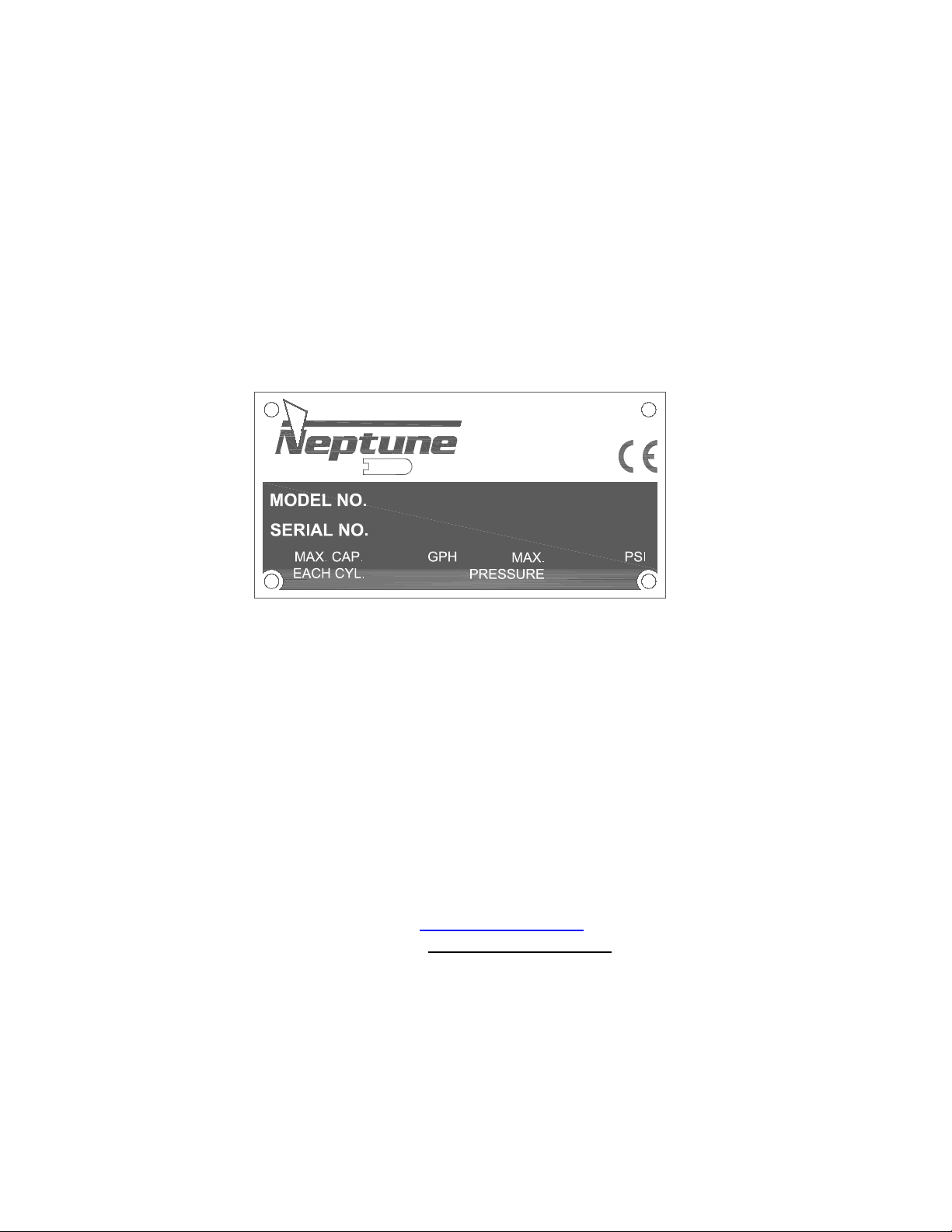
PARTS ORDERING INSTRUCTIONS
The complete model number and serial number of the pump must be furnished to insure
prompt and accurate parts service. These numbers are found on the name plate (sample
below) located on the back cover of the pump.
Please refer to page number (17), (18), (19) for parts list. Ballooned drawing of the pumps
can be found on pages (13), (14), (15), (16) and (18).
Spare Parts Kits are found on page 21.
Send all orders or inquiries for parts to:
Parts Department
Neptune Chemical Pump Company, Inc.
295 DeKalb Pike
North Wales, PA 19454
Tel.: 215-699-8700
1 -888-3NEPTUNE (888-363-7886)
FAX: 215-699-0370
Web: www.neptune1.com
Email: pump@neptune1.com
NOTE: PLEASE SUPPLY BOTH MODEL AND SERIAL NUMBERS.
8
1.0 GENERAL
1.0.1 UNPACKING & INSPECTION
When unpacking a pump or chemical feed system, be certain that no parts are thrown away. Examine the
equipment for possible damage. If damage has occurred, file claim with the common carrier within 24
hours. Neptune will assist in estimating the repair costs.
1.0.2 The Mechanically Actuated Diaphragm metering pumps should be located on a level surface. Four
mounting holes are provided to anchor the pump base securely to the mounting surface. All piping to the
pump should be supported to prevent stress on the pump inlet and discharge fittings.
1.0.3 Before connecting the pump make sure that all fittings are completely clean by flushing thoroughly.
Foreign matter with sharp edges entering the pump can damage the diaphragm and severely limit the life
of the pump.
1.0.4 A “Y” STRAINER (AT LEAST ONE PIPE SIZE LARGER THAN SUCTION PORT SIZE OF THE PUMP)
MUST BE INSTALLED IN THE SUCTION LINE OF THE PUMP TO INSURE AGAINST FOREIGN
MATTER ENTERING THE PUMP
1.0.5 It is recommended that isolation valves and unions be placed in the suction and discharge lines if
possible. Such an arrangement will facilitate servicing the pump.
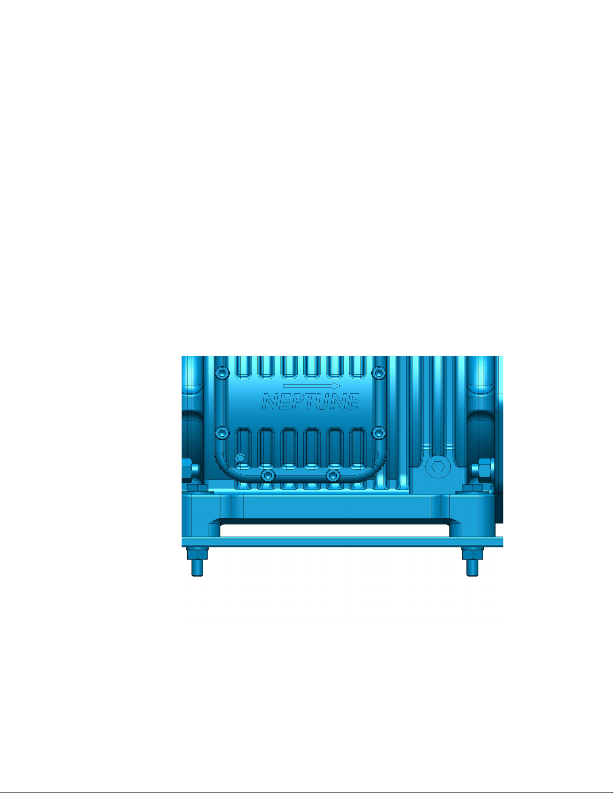
1.0.6 The electrical supply to the pump must match the motor nameplate characteristics. The motor rotation is
counterclockwise when viewed from the top of the motor or looking down on the pump. An arrow mark on
the side cover of the gearbox is indicating the correct rotation (Figure 1).
SECTION II
INSTALLATION INSTRUCTIONS
FIGURE 1
Operation with the incorrect rotation will damage the pump and motor.
IMPORTANT: On single-phase units, the rotation is set at the factory and must not be changed
1.0.7 Fill gearbox and pump by removing the breather and pouring the specified gear oil (drive lubricant) or oil
provided with pump through the Breather port. Pour oil in slowly until it covers the worm gear.
1.0.8 For dry pump (pump shipped from factory without oil) the oil volume is 27ozs (800cc) to fill the pump.

9
Alternate Oils
Manufacturer
Mobil Delvac Gear Oil 80W-90
Mobil Oil
Pennzoil® Gearplus®SAE 80W- 90 GL-5 Gear Oil
Pennzoil
The oil supplied by Neptune is:
PREMIUM PERFORMANCE HYPOID GEAR OIL SAE 80W-90,
Common sources for Gear Oil are:
Spirax S3 80W-90 Advance transmission Hypoid Gear Oil Shell Oil
NOTE: THE FACTORY SUPPLIED CHECK VALVES ARE FITTED WITH VITON O-RINGS. CHECK CHEMICAL
COMPATIBILITY, IF NOT COMPATIBLE REPLACE WITH SUPPLIED TEFLON O-RINGS.
All piping systems should include:
1.1.1 A separate system relief valve to protect piping and process equipment, including the pump, from excess
process pressures.
MULTIGEAR 80W-90
Geartex EP-A 85W-90
Texaco
*An external relief valve is required to safeguard pump and the piping system.
1.1.2 Isolation valves and unions (or flanges) on suction and discharge piping. This permits check valve
inspection without draining long runs of piping. Isolation valves should be of the same size as
connecting pipe. Full flow ball valves are preferred since they offer minimum flow restriction.
1.1.3 An inlet strainer, if the product is not slurry. Pump check valves are susceptible to dirt and other solid
contaminants unless designed for that service, and any accumulation can cause malfunction. The strainer
should be located between the suction isolation valve and the pump suction check valve. It must be sized
to accommodate the flow rate and the anticipated level of contamination. A 100-mesh screen size is
recommended.
1.1.4 Check valve housings or other portions of the liquid head must not support piping weight, as the resulting
stresses can cause leaks. In piping assembly, use a sealing compound chemically compatible with the
process material.
SUCTION PRESSURE REQUIREMENTS
Although Mechanical Diaphragm metering pumps have suction lift capability, a flooded suction is
preferable whenever possible. The pump should be located as close as possible to the suction side
reservoir or other source keeping suction piping as short as possible.
The pump will self-prime with 10 ft. (3 meters) of water suction lift (wetted valves, zero back pressure, full
stroke and speed, water like solutions). A foot valve is required to maintain prime. Once primed, the
pump is capable of up to 20 feet (6 meters) of water suction lift.
Neptune Mechanically Actuated Diaphragm metering pumps are designed for continuous service at the
rated discharge pressure. The discharge pressure must exceed suction pressure by at least 25 psiA (or
1.75 Bar). This can be achieved where necessary by the installation of a backpressure valve in the
discharge line.
2.0 SUCTION PIPING
2.0.1 The suction piping to the pump must be absolutely airtight for optimum operation any leakage in the
suction line will reduce or even eliminate pumping capacity. Suction pipe should be at least one size
larger than suction port size of the pump’s Liquid Head. It is suggested that the suction piping be tested
with low air pressure and a soap solution to assure that no leaks exist. Limit the total length of the suction
line to 5-8 feet for suction lift or 8-10 feet for flooded suction. Minimize bends, elbows, or other restrictions
for better pumping efficiency.
2.0.2 NEPTUNE RECOMMENDS THAT THE MECHANICALLY ACTUATED DIAPHRAGM METERING

10
PUMPS BE OPERATED WITH A FLOODED SUCTION, AS THIS WILL FACILITATE START-UP AND
INCREASE THE SERVICE LIFE OF THE PUMP.
2.0.3 It is recommended that all solution tanks be furnished with a low level cut off switch or low-level alarm
and cut off switch to prevent the pump from running dry. Although the pump can run dry for a few
minutes, OPERATION AGAINST A DRY SYSTEM UNDER THE PRESSURE FOR A PROLONGED
PERIOD MAY CAUSE DAMAGE TO THE PUMP DIAPHRAGM AND REDUCE THE OPERATING LIFE
OF THE PUMP.
3.0 DISCHARGE PIPING
3.0.1 It is recommended that the Mechanically Actuated Diaphragm metering pump operate against a suitable
back pressure to facilitate better operation of the check valves.
3.0.3 To protect the pump, it is recommended that an external relief valve as manufactured by Neptune Chemical
Pump Company, or equal, be placed in the discharge line of the pump to avoid over pressure.
3.0.4 Discharge piping should at least equal to discharge port size of the pump’s Liquid Head.
NOTE: All pipes and valves must have a working pressure at least twice the system maximum pressure.
CAUTION : Do not attempt to run the pump in excess of its nameplate rating.
4.0 INSTALLATION OUTDOORS
The Mechanically Actuated Diaphragm metering pump is a totally enclosed pump, which can be used outdoors or
indoors. When installed outdoors, make sure that the pump is protected against extremes of nature as follows:
4.0.1 Running of the pump when exposed to tropical sunshine with ambient temperature above 100°F (37.8°C)
would cause excessive oil and motor temperatures. The pump should be shaded and located in such a
way as to permit an ample degree of air circulation.
Under cold conditions, the pump should be insulated and a heat tracing should be supplied in order to
4.0.2
maintain the hydraulic fluid at an ambient temperature above 36°F (2°C.)
5.0 START UP PROCEDURE
The following start up procedure is complete and does repeat instructions on filling the gearbox and pump.
5.0.1 Open suction and discharge valves. (See recommendation 1.0.5)
5.0.2 Adjust backpressure close to zero.
5.0.3 Start pump.
5.0.4 On initial start-ups: Check for proper motor rotation (Refer to Paragraph 1.0.6). Listen for any abnormal
motor or crank noises, and if present, refer to trouble shooting chart (page 20)
5.0.5 Adjust system pressure to requirement.
SECTION III
NORMAL MAINTENANCE
6.0 MAINTENANCE
Under normal conditions, the Mechanically Actuated Diaphragm metering pumps should not require any
 Loading...