

Page 1

NEP-ZL130009
INSTALLATION
OPERATION &
MAINTENANCE
NEPTUNE
Series 7000
Mechanical
“dia-PUMP”
Models
MP7007, MP7010,
MP7015
03.2018_REV 3
Page 2

1
WARNING
SAFETY INSTRUCTIONS:
LOCKOUTS ARE REQUIRED BEFORE
SERVICING THIS EQUIPMENT.
Shut off/Lockout Pump Power before Servicing.
Be certain pump isolation valves are
Closed and chemical is shut off.
Bleed pressure before servicing.
Page 3

2
WARNING
Please read thoroughly before installation, operation or maintenance of any Neptune pump
EQUIPMENT MISUSE HAZARD
Equipment misuse can cause the equipment to rupture, malfunction and result in serious injury.
• This equipment is for professional use only.
• Read all instruction manuals, tags and labels before operating the equipment.
• Use the equipment only for its intended use.
• Do not alter or modify this equipment.
• Be certain all operators of this equipment have been trained for safe working practices,
understand its limitations and wear safety goggles and or equipment when required
• Do not exceed the maximum working pressure of the system as mentioned on the pump tag.
• Do not use the pump head or the suction or discharge piping to pull the equipment.
• Do not move pressurized pump.
• Use fluids or cleaning agents for cleaning that are compatible with the pump parts. Read the
fluid and cleaning agent manufacturer’s warning and also refer to the material compatibility
chart.
• Comply with all applicable local, state and national safety regulations.
• Do not allow the pump to run dry for long periods.
PRESSURIZED EQUIPMENT HAZARD
Spray from leaks, ruptured components can splash fluid in eyes or on skin and cause serious injury.
Leaks from ruptured components • • • • • •
• Shut off the pump and depressurize before performing any maintenance.
• Do not tamper with or perform unspecified alteration of the device.
• Use only pipes, hoses and hose fittings rated for maximum rated pressure of the pump or the
pressure at which the pressure relief valve is set at.
• Always wear protective clothing, face shield, safety glasses and gloves when working on or
near the metering pump.
• Additional precautions should be taken depending on the solution being pumped. Refer to
SDS precautions from your solution supplier.
• Do not stop or deflect fluid leaks with your hands, body, gloves or rags.
• Tighten all fluid connections before operating the equipment.
• Replace worn damaged or loose parts immediately.
• Before performing any maintenance requiring pump head and or valve (wetting parts)
disassembly, be sure to relieve pressure from the piping system and where hazardous process
chemicals are present.
• Make the pump safe to handle for individuals and the environment by leaning and
chemically neutralizing the pump when appropriate.
• Wear protective clothing and use proper tools as appropriate to avoid any injury.
Page 4

3
FIRE AND EXPLOSION HAZARD
Improper grounding, poor air ventilation, open flames, or sparks can cause a hazardous condition and result in
fire or explosion and serious injury.
Ground the equipment. See motor installation instruction for grounding procedure.
correct the problem before starting up the pump.
TOXIC FLUID HAZARD
Hazardous fluids or toxic fumes can cause serious injury or death if splashed in eyes or on the skin,
Know the specific hazards of the fluid you are using. Read the fluid manufactures warnings.
with the air in mechanical diaphragm pump.
SOUND HAZARD
The sound pressure level of the pump may exceed 80dBA in some pumps.
Observe all safety precautions when operating the pump within close proximity for extended
tinnitus, tiredness, stress, and other effects such as loss of balance and awareness.
MECHANICAL HAZARD
The pump may shake or vibrate during operation.
Vibration could occur due to loose mechanical component and foundation bolts, causing
•
• Do not pump non recommended flammable or explosive fluids.
• Static electricity may generate by fluid moving through pipes and hoses. A static spark could
be produced by high fluid flow rates. Grounding of the pump is a must.
• Provide fresh air ventilation to avoid the possible buildup of flammable fumes from the
process chemicals.
• Keep the pump area free of debris, including cleaning agent, rags, and any flammable material.
• Follow the cleaning agent and other cleaning recommendations as mentioned in the operation
and instruction manuals.
• Use cleaning agent with the highest possible flash point to clean the pump parts if needed.
• If there is any static sparking while using the equipment, stop operation at once. Identify and
swallowed, or inhaled.
•
• Store hazardous fluid in an approved container. Dispose of hazardous fluid according to all
local, state and national guidelines.
• Wear the appropriate protective clothing, gloves, eyewear and respirator.
• Pipe and dispose of the exhaust air safely. If diaphragm fails, the fluid may be exhausted along
•
periods by wearing hearing protectors.
• Extended exposure to elevated sound levels will result in permanent loss of hearing acuteness,
•
piping rupture and leakage of chemical to cause bodily injury. The pump should be bolted
down to the base during operation.
• Pump may overturn when being transported if the motor is too heavy. Secure the pump on its
base before transportation.
Page 5

4
LIST
GEAR BOX PARTS LIST PER MODEL
18-20
V
MECHANICALLY ACTUATED PUMP
SECTION PARAGRAPH TABLE OF CONTENTS PAGE
I
II
III
1
2
3
4
5
6
GENERAL DESCRIPTION 5
LIMITED WARRANTY 6
PARTS ORDERING INSTRUCTIONS 7
INSTALLATION INSTRUCTIONS
GENERAL
SUCTION PIPING
DISCHARGE PIPING
INSTALLATION OUTDOORS
STARTUP PROCEDURE
NORMAL MAINTENANCE
MAINTENANCE
PARTS LIST 17
COMMON PARTS
8
9
10
10
10
11
17
IV 7 MOTOR OPERATING CONDITIONS 21
TROUBLE SHOOTING CHART 21
DRAWINGS
MODEL MP7007-BN3
CROSS SECTION (HEAD AREA) MP7015-DN3, 5, 8
SPARE PARTS KITS 22-23
PUMP DATA / MAINTENANCE LOG
13-16
20
24
Page 6

5
SECTION I
GENERAL DESCRIPTION
The Neptune MP7000 Mechanical Diaphragm metering pump is a reliable metering pump of the low-pressure diaphragm
type. Under constant conditions of temperature, pressure, and capacity setting, a +/- 2% metered discharge volume is
maintained. Rugged contoured composite diaphragm designed for high metering accuracy over a full 10:1 turndown
range.
A reciprocating rod at a set stroke length and rate actuates a flexible, chemically inert, Teflon faced diaphragm creating
the pumping action. Screwing in and out a hand knob regulates the capacity of the pump. Screwing in shortens the stroke
length reducing the volume and screwing out increases capacity. A percentage of flow is read on the hand knob.
Precision-engineered liquid ends meters mild solutions, aggressive chemicals, high viscosity polymers (up to 200cP) and
slurries (hydrated lime slurries up to 4 lb/gallon of water, activated carbon slurries up to 1 lb/gallon of water). If metering of
liquids with higher viscosity is required please contact factory
Metering accuracy is maintained by the ball check valves in the suction and discharge pump heads. Screw-in cartridge
ball check valves eases maintenance.
Temperature limitations on the plastic heads are: 36 – 125°F (2 - 52°C) for PVC; 36 - 200°F (2-93°C) for PVDF.
PLEASE READ INSTRUCTION MANUAL COMPLETELY BEFORE INSTALLING PUMP.
Page 7

6
SECTION I
IMPORTANT NOTICE
NEPTUNE CHEMICAL PUMP COMPANY
LIMITED WARRANTY
All Neptune Pumps are tested at the factory prior to shipment. Each part used in their construction has been carefully
checked for workmanship.
If the pump is installed properly, Neptune Chemical Pump Company warrants to the purchaser of this product for a period
of thirty six (36) months from the date of shipment, this product shall be free of defects in material and/or workmanship, as
follows:
1 Neptune Chemical Pump Company will replace, at no charge, any part that fails due to a defect in material and/or
workmanship during the warranty period, FOB our factory, North Wales, Pennsylvania. To obtain warranty service,
you must forward the defective parts to the factory for examination, freight pre-paid.
2 This warranty period does not cover any product or product part, which has been subject to accident, misuse,
abuse or negligence. Neptune Chemical Pump Company shall only be liable under this warranty if the product is
used in the manner intended by the manufacturer as specified in the written instructions furnished with this
product. The warranty does not cover any parts clearly defined as consumables by Neptune Chemical Pump
Company (such as, diaphragm, suction/discharge valves, oil seal, gaskets and sealing rings, elastomeric parts,
etc.).
3 The accessories, optional components and other supporting devices (including motor) with nameplates are under
the warranty of their OEM; the accessories, optional components and other supporting devices (including motor)
with Neptune Chemical Pump Company nameplates or without any nameplates are under Neptune Chemical
Pump Company warranty for a period of one (1) year.
Any express warranty not provided in this warranty document, and any remedy for breach of contract that, but for this
provision, might arise by implication or operation of law, is hereby excluded and disclaimed. Under no circumstances shall
Neptune Chemical Pump Company be liable to purchaser or any other person for any charge for labor, repairs, or parts,
performed or furnished by others, nor for any incidental consequential damages, whether arising out of breach of warranty,
express or implied, a breach of contract or otherwise. Except to the extent prohibited by applicable law, any implied warranty
of merchantability and fitness for a particular purpose are expressly limited in duration to the duration of this limited warranty.
Some states do not allow the exclusion or limitation of incidental or consequential damages, or allow limitations on how long
any implied warranty lasts, so the above limitations may not apply to you. This warranty gives you specific legal rights, and
you may have other rights, which may vary from state to state.
1
IMPORTANT
SHOULD IT BE NECESSARY TO SEND THE PUMP TO THE FACTORY OR AN AUTHORIZED NEPTUNE REPAIR
FACILITY FOR REPAIR OR MAINTENANCE REBUILDING; DRAIN ALL CHEMICAL FROM PUMP BEFORE SHIPPING.
FAILURE TO DO SO CAN CAUSE EXTENSIVE DAMAGE TO THE MOTOR.
SEE IMPORTANT NOTICE – RETURN GOODS AUTHORIZATION
1
(1) All equipment returned to Neptune Chemical Pump Company or a Neptune Authorized Repair
Center Requires a Proper Returned Goods Authorization Number (RGA) and tags.
(2) All equipment returned to the factory or a Neptune Authorized Repair Center for repair or service
must first be thoroughly flushed and have all chemical contact areas neutralized.
(3) All equipment which has been in contact with chemicals must be accompanied by a copy of the
chemical product material Safety Data Sheet (SDS).
(4) Failure to comply with the above instructions will result in equipment being returned to sender,
freight collect, without service.
RETURN GOODS AUTHORIZATION
Page 8
7
SECTION I
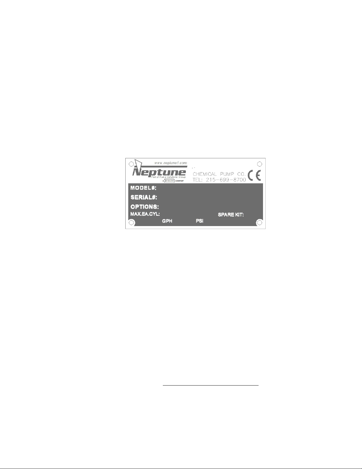
PARTS ORDERING INSTRUCTIONS
The complete model number and serial number of the pump must be furnished to insure
prompt and accurate parts service. These numbers are found on the name plate (sample
below) located on the back cover of the pump.
Please refer to page number (17), (18), (19), (20) for parts list. Ballooned drawing of the
pumps can be found on pages (13), (14), (15), (16) and (20).
Spare Parts Kits are found on pages 22 and 23.
Send all orders or inquiries for parts to:
Parts Department
Neptune Chemical Pump Company, Inc.
295 DeKalb Pike
North Wales, PA 19454
Tel.: 215-699-8700
1 -888-3NEPTUNE (888-363-7886)
FAX: 215-699-0370
Web: www.Neptune1.com
Email: neptune.sales@psgdover.com
NOTE: PLEASE SUPPLY BOTH MODEL AND SERIAL NUMBERS.
Page 9

8
SECTION II
INSTALLATION INSTRUCTIONS
1.0 GENERAL
1.0.1 UNPACKING & INSPECTION
When unpacking a pump or chemical feed system, be certain that no parts are thrown away. Examine the
equipment for possible damage. If damage has occurred, file a claim with the common carrier within 24
hours. Neptune will assist in estimating the repair costs.
1.0.2 The Mechanically Actuated Diaphragm metering pumps should be located on a level surface. Four
mounting holes are provided to anchor the pump base securely to the mounting surface. All piping to the
pump should be supported to prevent stress on the pump inlet and discharge fittings.
1.0.3 Before connecting the pump make sure that all fittings are completely clean by flushing thoroughly.
Foreign matter with sharp edges entering the pump can damage the diaphragm and severely limit the life
of the pump.
1.0.4 A “Y” STRAINER (AT LEAST ONE PIPE SIZE LARGER THAN SUCTION PORT SIZE OF THE PUMP)
MUST BE INSTALLED IN THE SUCTION LINE OF THE PUMP TO INSURE AGAINST FOREIGN
MATTER ENTERING THE PUMP
1.0.5 It is recommended that isolation valves and unions be placed in the suction and discharge lines if
possible. Such an arrangement will facilitate servicing the pump.
1.0.6 The electrical supply to the pump must match the motor nameplate characteristics. The motor rotation is
counterclockwise when viewed from the top of the motor or looking down on the pump.
1.0.7 Do not fill pump with oil. Pump is designed with oil free gearbox.
IMPORTANT: On single-phase units, the rotation is set at the factory and must not be changed
Page 10

9
NOTE: THE FACTORY SUPPLIED CHECK VALVES ARE FITTED WITH VITON O-RINGS. CHECK CHEMICAL
COMPATIBILITY, IF NOT COMPATIBLE REPLACE WITH SUPPLIED TEFLON O-RINGS.
All piping systems should include:
1.1.1 A separate system relief valve to protect piping and process equipment, including the pump, from excess
process pressures.
*An external relief valve is required to safeguard pump and the piping system.
1.1.2 Isolation valves and unions (or flanges) on suction and discharge piping. This permits check valve
inspection without draining long runs of piping. Isolation valves should be of the same size as
connecting pipe. Full flow ball valves are preferred since they offer minimum flow restriction.
1.1.3 An inlet strainer, if the product is not slurry. Pump check valves are susceptible to dirt and other solid
contaminants unless designed for that service, and any accumulation can cause malfunction. The strainer
should be located between the suction isolation valve and the pump suction check valve. It must be sized
to accommodate the flow rate and the anticipated level of contamination. A 100-mesh screen size is
recommended.
1.1.4 Check valve housings or other portions of the liquid head must not support piping weight, as the resulting
stresses can cause leaks. In piping assembly, use a sealing compound chemically compatible with the
process material.
SUCTION PRESSURE REQUIREMENTS
Although Mechanical Diaphragm metering pumps have suction lift capability, a flooded suction is
preferable whenever possible. The pump should be located as close as possible to the suction side
reservoir or other source keeping suction piping as short as possible.
The pump will self-prime with 10 ft. (3 meters) of water suction lift (wetted valves, zero back pressure, full
stroke and speed, water like solutions). A foot valve is required to maintain prime. Once primed, the
pump is capable of up to 20 feet (6 meters) of water suction lift.
Neptune Mechanically Actuated Diaphragm metering pumps are designed for continuous service at the
rated discharge pressure. The discharge pressure must exceed suction pressure by at least 25 psiA (or
1.75 Bar). This can be achieved where necessary by the installation of a backpressure valve in the
discharge line.
2.0 SUCTION PIPING
2.0.1 The suction piping to the pump must be absolutely airtight for optimum operation. Any leakage in the
suction line will reduce or even eliminate pumping capacity. Suction pipe should be at least one size
larger than suction port size of the pump’s Liquid Head. It is suggested that the suction piping be tested
with low air pressure and a soap solution to assure that no leaks exist. Limit the total length of the suction
line to 5-8 feet for suction lift or 8-10 feet for flooded suction. Minimize bends, elbows, or other restrictions
for better pumping efficiency.
2.0.2 NEPTUNE RECOMMENDS THAT THE MECHANICALLY ACTUATED DIAPHRAGM METERING
PUMPS BE OPERATED WITH A FLOODED SUCTION, AS THIS WILL FACILITATE START-UP AND
INCREASE THE SERVICE LIFE OF THE PUMP.
2.0.3 It is recommended that all solution tanks be furnished with a low level cut off switch or low-level alarm
and cut off switch to prevent the pump from running dry. Although the pump can run dry for a few
minutes, OPERATION AGAINST A DRY SYSTEM UNDER PRESSURE FOR A PROLONGED PERIOD
MAY CAUSE DAMAGE TO THE PUMP DIAPHRAGM AND REDUCE THE OPERATING LIFE OF THE
PUMP.
Page 11

10
3.0 DISCHARGE PIPING
3.0.1 It is recommended that the Mechanically Actuated Diaphragm metering pump operate against a suitable
back pressure to facilitate better operation of the check valves.
3.0.2 To protect the pump, it is recommended that an external relief valve as manufactured by Neptune Chemical
Pump Company, or equal, be placed in the discharge line of the pump to avoid over pressure.
3.0.3 Discharge piping should at least equal to discharge port size of the pump’s Liquid Head.
NOTE: All pipes and valves must have a working pressure at least twice the system maximum pressure.
CAUTION: Do not attempt to run the pump in excess of its nameplate rating.
4.0 INSTALLATION OUTDOORS
The Mechanically Actuated Diaphragm metering pump is a totally enclosed pump, which can be used outdoors or
indoors. When installed outdoors, make sure that the pump is protected against extremes of nature as follows:
4.0.1 Running of the pump when exposed to tropical sunshine with ambient temperature above 100°F (37.8°C)
would cause excessive motor temperatures. The pump should be shaded and located in such a way as to
permit an ample degree of air circulation.
5.0 START UP PROCEDURE
The following start up procedure is complete and does repeat instructions on filling the gearbox and pump.
5.0.1 Open suction and discharge valves. (See recommendation 1.0.5)
5.0.2 Set capacity control knob to indicate zero by turning clockwise.
5.0.3 Adjust backpressure close to zero.
5.0.4 Start pump.
5.0.5 On initial start-ups: Check for proper motor rotation (Refer to Paragraph 1.0.6). Listen for any abnormal
motor or crank noises, and if present, refer to trouble shooting chart (page 21)
5.0.6 Adjust pump to required capacity by turning hand knob counterclockwise.
5.0.7 Adjust system pressure to requirement.
Page 12

11
SECTION III
NORMAL MAINTENANCE
6.0 MAINTENANCE
Under normal conditions, the Mechanically Actuated Diaphragm metering pumps should not require any
significant amount of maintenance. The liquid end of the pump should also be inspected for leakage and check
the liquid head bolt torque. These observations should be made regularly.
6.1.0 CHECK VALVE REMOVAL CLEANING AND REPLACEMENT.
Should the valves need cleaning, remove as follows:
6.1.1 Disconnect the power source to the drive motor.
6.1.2 Relieve all pressure from the piping system.
6.1.3 Close the isolation valves on suction and discharge piping.
6.1.4 Loosen and remove the suction and discharge check valves gradually to drain any trapped
liquid.
6.1.5 Clean valves with suitable solvent. Both valves are complete and integral units and should
not be disassembled for cleaning. If the valves are found to be worn and in need of
replacement, an entire valve in either suction or discharge should be ordered.
6.1.6 To replace, reverse above procedures. Make sure that the port orientation is correct.
6.1.7 For valves with O-rings make sure that the O-rings are in good condition. Install new
O-rings if necessary.
6.2.0 LIQUID HEAD REMOVAL, INSPECTION, AND REINSTALLATION
CAUTION: If the diaphragm failed, process fluid will pass through the bleed hole located behind the diaphragm. Handle any liquid with appropriate care.
(Refer to liquid manufacturer’s SDS)
Mechanical diaphragms should operate for approximately 2000+ hours under normal operating
conditions; however, the accumulation of foreign material or debris and abnormal operating condition
or simply age can cause failure. Failure can also occur as a result of hot pumping fluid or system over
pressure. Periodic diaphragm inspection and replacement are recommended.
6.2.1 Adjust the stroke control knob to “0” and disconnect the power source to the drive motor.
6.2.2 Relieve all system pressure from the piping system.
6.2.3 Take all precautions described under “Caution” to prevent environmental and personnel
exposure to hazardous materials.
6.2.4 Disconnect piping to the Liquid Head and drain any process liquid.
6.2.5 Place a pan underneath the pump head adaptor to catch any liquid leakage.
6.2.6 Remove all but two top Liquid Head bolt. Process fluid will leak out between the pump head
adaptor and Liquid Head as the bolts are loosened.
Page 13

12
6.2.7 Tilt the head and pour out any liquids retained by the check valves into a suitable container,
continue to follow safety precautions as appropriate.
6.2.8 Remove the final bolt and rinse or clean the Liquid Head with an appropriate material.
6.2.9 Inspect the diaphragm. The diaphragm must be replaced if it is cracked, separated, or
obviously damaged. Remove the diaphragm if necessary, by turning counter-clockwise.
6.2.10 To install a diaphragm, first ensure that the critical sealing areas of: diaphragm, Liquid Head,
and pump head adapter are clean and free of debris. Assemble the diaphragm with backup
plate (item #35). For MP7015-D3N, 5, 8 install spacer nut (item #50) onto the diaphragm
threads.
6.2.11 Thread the diaphragm (clockwise) completely on the push rod.
6.2.12 Install the liquid head, faceplate (for plastic heads), and bolts. Tighten bolts in an alternating
crossing pattern to ensure an even pressure on all bolts. Recommended torque is 12-13 ft-lb
for heads on MP7015-DN3, DN5, N8 pumps.
Page 14

13
MODEL MP7007-BN3 MECHANICALLY ACTUATED PUMP
(SHOWN WITH “B” 316SS LIQUID HEAD)
VERTICAL CROSS SECTION
Page 15

14
HORIZONTAL CROSS SECTION A-A
Page 16

15
PUMP SIDE VIEW (LEFT SIDE)
Page 17

16
PUMP SIDE VIEW (RIGHT SIDE)
Page 18

17
PARTS LIST
ITEM NO.
PART NO.
DESCRIPTION
QTY
1
004960
LOW VOLUME MAD PUMP BODY
1 2 004987
STROKE CONTROL ASSEMBLY MP7000
1 4 106106
SHCS 10-32 X 5/8
10
5
004990
CARRIER PLATE ASSEMBLY MP7000
1
7
005196
WEAR STRIP MP7000
1 8 129313
FHCS 10-32 X 1/2"
2
12
121081
BEARING 6203 17MM
2
13
121080
BEARING 5205 20MM
1
14
004956
BEARING HOLDER, MP7000, PUMPS
1
15
121082
EXTERNAL RETAINING RING
1
16
121083
EXTERNAL RETAINING RING
1
17
121084
INTERNAL RETAINING RING
1
18
105532
O-RING BUNA #2-145
1
19
004958
SIDE COVER MP7000
1
20
121200
KEY 5MM SQ. X 40MM ROUND ENDS
1
21
121202
O-RING VITON #2-131
1
22
004966
MOUNTING FLANGE GEARBOX MP7000
1
23
121198
SHCS M6 X 14MM
4
25
004964
SPRING GUIDE MP7000
1
26
121089
SPRING
1
27
005343
FRONT COVER MP7000 PUMP
1
28
121125
O-RING VITON #2-246
1
29
106693
O-RING VITON #2-031
1
30
100211
SHCS 1/4-20 X 5/8
4
31
121111
SECONDARY DIAPHRAGM
1
32
121204
RETAINING RING INTERNAL 1-1/2" BORE
1
39
004989
BASE ADAPTER FOR L.V. PUMP
1
40
104563
O-RING VITON #2-250
1
41
104637
STEEL BASE
1
42
109962
PUMP TAG
1
43
100209
DRIVE CREW
4
44
100106
HEX HEAD PLTD SCREW 1/4-20 X 1 1/2"LG
2
45
106539
1/4-20 HEX NUT/NYLON/WHITE
2
46
108426
WASHER FLAT 1/4 316SS
4
48
129874
SHCS 10-32 X 1 1/2" LG
6
49
129875
FLAT WASHER #10
6
COMMON PARTS LIST
Page 19

18
PARTS LIST PER MODEL
ITEM NO.
PART NO.
DESCRIPTION
QTY
2
004987
STROKE CONTROL ASSEMBLY MP7000
1 7 129863
SHIM SPRING STEEL 1/2 X 3/4 X .010
2
9
004955
CAM SHAFT, MP7000, .125"
1
22
129423
RIGHT ANGLE GEARBOX, 7.5:1
1
31
004969
HEAD ADAPTER, MP7000
1
32
005384
LIQUID HEAD MP7000, A, 316SS
1
005375
LIQUID HEAD MP7000, A, PVC
1 005387
LIQUID HEAD MP7000, A, PVDF
1
33
005207
CHECK VALVE MP7000, A, 316SS SUCTION
1
005205
CHECK VALVE MP7000, A, PVC SUCTION
1 005206
CHECK VALVE MP7000, A, PVDF SUCTION
1
34
005210
CHECK VALVE MP7000, A, 316SS DISCHARGE
1
005208
CHECK VALVE MP7000, A, PVC DISCHARGE
1 005209
CHECK VALVE MP7000, A, PVDF DISCHARGE
1
35
004967
BACKUP PLATE MP7000
1
36
005338
"A" DIAPHRAGM ASSEMBLY
1
ITEM NO.
PART NO.
DESCRIPTION
QTY
2
004987
STROKE CONTROL ASSEMBLY MP7000
1 7 129863
SHIM SPRING STEEL 1/2 X 3/4 X .010
1
8
129864
SHIM SPRING STEEL 1/2 X 3/4 X .005
1
9
004955
CAM SHAFT, MP7000, .125"
1
22
129423
RIGHT ANGLE GEARBOX, 7.5:1
1 129424
RIGHT ANGLE GEARBOX, 10:1
1
129425
RIGHT ANGLE GEARBOX, 15:1
1
31
004970
HEAD ADAPTER, MP7000
1
32
005385
LIQUID HEAD MP7000, B, 316SS
1 005376
LIQUID HEAD MP7000, B, PVC
1
005388
LIQUID HEAD MP7000, B, PVDF
1
33
005299
CHECK VALVE MP7000, B, 316SS SUCTION
1 005297
CHECK VALVE MP7000, B, PVC SUCTION
1 005298
CHECK VALVE MP7000, B PVDF SUCTION
1
34
005302
CHECK VALVE MP7000, B, 316SS DISCHARGE
1
005300
CHECK VALVE MP7000, B, PVC DISCHARGE
1 005301
CHECK VALVE MP7000, B, PVDF DISCHARGE
1
35
004968
BACKUP PLATE MP7000
1
36
005339
"B" DIAPHRAGM ASSEMBLY
1
“A” PUMPS MP7007-AN3, -AN5, -AN8
“B” PUMPS MP70XX-BN3, -BN5, -BN8
Page 20

19
ITEM NO.
PART NO.
DESCRIPTION
QTY
2
004987
STROKE CONTROL ASSEMBLY MP7000
1 9 005378
CAM SHAFT, MP7000, .105"
1
22
129423
RIGHT ANGLE GEARBOX, 7.5:1
1
129424
RIGHT ANGLE GEARBOX, 10:1
1 129425
RIGHT ANGLE GEARBOX, 15:1
1
31
005200
HEAD ADAPTER, MP7000
1
32
005386
LIQUID HEAD MP7000, C, 316SS
1
005377
LIQUID HEAD MP7000, C, PVC
1 005389
LIQUID HEAD MP7000, C, PVDF
1
33
005225
CHECK VALVE MP7000, C, 316SS SUCTION
1
005213
CHECK VALVE MP7000, C, PVC SUCTION
1
005219
CHECK VALVE MP7000, C PVDF SUCTION
1
34
005226
CHECK VALVE MP7000, C, 316SS DISCHARGE
1 005214
CHECK VALVE MP7000, C, PVC DISCHARGE
1
005220
CHECK VALVE MP7000, C, PVDF DISCHARGE
1
35
005199
BACKUP PLATE MP7000
1
36
005340
"C" DIAPHRAGM ASSEMBLY
1
ITEM NO.
PART NO.
DESCRIPTION
QTY
55
005409
PRIMING VALVE KIT 316SS
1 005410
PRIMING VALVE KIT PVC
1 005411
PRIMING VALVE KIT PVDF
1
ITEM NO.
PART NO.
DESCRIPTION
QTY
56
(Not Shown)
005407
FOOT VALVE ASSEMBLY 316SS
1 005406
FOOT VALVE ASSEMBLY PVC
1
005408
FOOT VALVE ASSEMBLY PVDF
1
“C” PUMPS MP70XX-CN3, -CN5, -CN8
PRIMING VALVE KITS FOR “A”, “B” & “C” PUMP HEADS
FOOT VALVES FOR “A”, “B” & “C” PUMPS (OPTIONAL)
Page 21

20
“D” PUMPS MP7015-DN3, -DN5, -DN8, HEAD SECTIONS
ITEM NO.
PART NO.
DESCRIPTION
QTY
2
005020
STROKE CONTROL ASSEMBLY MP7000
1
9
005346
CAM SHAFT, MP7000, .5mm
1
22
129425
RIGHT ANGLE GEARBOX, 15:1
1
31
005349
HEAD ADAPTER, MP7000
1
32
005133
LIQUID HEAD MP7000, D, 316SS
1
004950
LIQUID HEAD MP7000, D, PVC
1
004951
LIQUID HEAD MP7000, D, PVDF
1
33
005011
CHECK VALVE MP7000, D, 316SS SUCTION
2 003279
CHECK VALVE MP7000, D, PVC SUCTION
2
003332
CHECK VALVE MP7000, D PVDF SUCTION
2
35
004774
BACKUP PLATE MP7000
1
36
005351
"D" DIAPHRAGM ASSEMBLY
1
50
104684
HEX JAM NUT 3/4-16
1
51
004858
HEAD PLATE (USED ON HEADS 5 & 8 ONLY)
1
52
106442
HEX HEAD BOLT 5/16-18 (USED ON HEADS 5 & 8 ONLY)
8
53
100069
FLAT WASHER 5/16 (USED ON HEADS 5 & 8 ONLY)
8
54
100206
SHCS 5/16-18 (USED ON HEAD 3 ONLY)
8
“D” PUMPS MP7015-DN3 “D” PUMPS MP7015-DN5, -DN8
“D” PUMPS MP70XX-DN3, -DN5, -DN8
Page 22

21
SECTION IV
SYMPTOMS
CAUSES
REMEDIES
1. Pump Motor Will Not
Operate.
A. Blown Fuse.
Check for short circuit or overload
B. Open thermal overload device in
starter.
Reset.
C. Low liquid level in tank (where low
level cut-off is used).
Fill tank.
D. Broken wire.
Locate and repair.
E. Low voltage.
Check for too light wiring.
2. Pump Does Not Deliver
Rated Capacity
A. Starved suction.
Look for blockage in suction line.
B. Leaky suction piping.
Replace suction piping with larger size.
Pressure test, repair or replace defective piping.
C. Excessive suction lift.
Rearrange equipment location to reduce suction lift.
D. Liquid too close to boiling point.
Lower temperature or increase suction pressure slightly.
E. Worn or dirty valves or seats, or
both
Clean or replace valve assembly.
F. Viscosity of liquid too high
1. Reduce viscosity by heating or other means
2. Increase size of suction piping
3. Increase suction pressure slightly
G. Low discharge pressure
A minimum discharge pressure of 25 psi is required to
insure proper capacity control
Repair or replace piping.
3. Pump delivers
erratically.
A. Leaky suction line.
Clean or replace valve assembly.
B. Worn or dirty valves or seats, or
both.
Increase backpressure.
C. Excessive excursion of ball valves
from seats (indicated by ball chatter).
Increase suction pressure.
D. Insufficient suction pressure
Raise tank level.
E. Liquid too close to boiling point,
Reduce temperature or raise suction pressure.
F Leaky system relief valve.
Repair or replace relief valve
4. Motor overheats thermal
overload activates,
A. Power supply does not match motor.
Check power supply against motor nameplate data.
B. Overload caused by operating pump
beyond rated capacity
Check operating pressure against pump manufacturer
data plate maximum rating
5. Noisy Operation
5.1. In Pump
A. Pump Valves.
Valves must move to open and close, and they will make
functioning.
5.2. In Gear Reducer
A. Pounding noise at high discharge
pressure
Fluid compressibility causes reversal of load on gears at
end of pressure stroke, Not considered detrimental.
MOTOR OPERATING CONDITIONS
7.0 The normal temperature rise for standard motors is 40°C above ambient temperature and, thus, it might appear
that the motor is operating at a higher than normal temperature. This situation is normal.
As a precaution against motor overheating, it is recommended that the pump be located where adequate
ventilation is available, It is also recommended that a MOTOR STARTER WITH THE PROPER OVERLOAD
PROTECTION BE SUPPLIED AS AN ADDITIONAL SAFETY DEVICE.
SECTION V
TROUBLESHOOTING CHART
a clicking noise as they operate. These noises are
sometimes amplified by natural resonances in piping
system. They are usually indications of normal valve
Page 23

22
SPARE PARTS KITS
ITEM
NO.
DESCRIPTION
QTY.
PART
NUMBER
36
DIAPHRAGM “A” ASSEMBLY
1
005338
KIT NUMBER 005357
33
CHECK VALVE ASSEMBLY SUCTION
1
005207
34
CHECK VALVE ASSEMBLY DISCHARGE
1
005210
ITEM
NO.
DESCRIPTION
QTY.
PART
NUMBER
36
DIAPHRAGM “A” ASSEMBLY
1
005338
KIT NUMBER 005358
33
CHECK VALVE ASSEMBLY SUCTION
1
005205
34
CHECK VALVE ASSEMBLY DISCHARGE
1
005208
ITEM
NO.
DESCRIPTION
QTY.
PART
NUMBER
36
DIAPHRAGM “A” ASSEMBLY
1
005338
KIT NUMBER 005359
33
CHECK VALVE ASSEMBLY SUCTION
1
005206
34
CHECK VALVE ASSEMBLY DISCHARGE
1
005209
ITEM
NO.
DESCRIPTION
QTY.
PART
NUMBER
36
DIAPHRAGM “B” ASSEMBLY
1
005339
KIT NUMBER 005360
33
CHECK VALVE ASSEMBLY SUCTION
1
005299
34
CHECK VALVE ASSEMBLY DISCHARGE
1
005302
ITEM
NO.
DESCRIPTION
QTY.
PART
NUMBER
36
DIAPHRAGM “B” ASSEMBLY
1
005339
KIT NUMBER 005361
33
CHECK VALVE ASSEMBLY SUCTION
1
005297
34
CHECK VALVE ASSEMBLY DISCHARGE
1
005300
ITEM
NO.
DESCRIPTION
QTY.
PART
NUMBER
36
DIAPHRAGM “B” ASSEMBLY
1
005339
KIT NUMBER 005362
33
CHECK VALVE ASSEMBLY SUCTION
1
005298
34
CHECK VALVE ASSEMBLY DISCHARGE
1
005301
ITEM
NO.
DESCRIPTION
QTY.
PART
NUMBER
36
DIAPHRAGM “C” ASSEMBLY
1
005340
KIT NUMBER 005363
33
CHECK VALVE ASSEMBLY SUCTION
1
005225
34
CHECK VALVE ASSEMBLY DISCHARGE
1
005226
ITEM
NO.
DESCRIPTION
QTY.
PART
NUMBER
36
DIAPHRAGM “C” ASSEMBLY
1
005340
KIT NUMBER 005364
33
CHECK VALVE ASSEMBLY SUCTION
1
005213
34
CHECK VALVE ASSEMBLY DISCHARGE
1
005214
ITEM
NO.
DESCRIPTION
QTY.
PART
NUMBER
36
DIAPHRAGM “C” ASSEMBLY
1
005340
KIT NUMBER 005365
33
CHECK VALVE ASSEMBLY SUCTION
1
005219
34
CHECK VALVE ASSEMBLY DISCHARGE
1
005220
MP7007-AN3
MP7007-AN5
MP7007-AN8
MP70XX-BN3
MP70XX-BN5
MP70XX-BN8
MP70XX-CN3
MP70XX-CN5
MP70XX-CN8
Page 24

23
ITEM
NO.
DESCRIPTION
QTY.
PART
NUMBER
36
DIAPHRAGM “D” ASSEMBLY
1
005351
KIT NUMBER 005366
33
CHECK VALVE ASSEMBLY
2
005011
ITEM
NO.
DESCRIPTION
QTY.
PART
NUMBER
36
DIAPHRAGM “D” ASSEMBLY
1
005351
KIT NUMBER 005367
33
CHECK VALVE ASSEMBLY
2
003279
ITEM
NO.
DESCRIPTION
QTY.
PART
NUMBER
36
DIAPHRAGM “D” ASSEMBLY
1
005351
KIT NUMBER 005368
33
CHECK VALVE ASSEMBLY
2
003332
MP7015-DN3
MP7015-DN5
MP7015-DN8
Page 25

24
PUMP DATA / MAINTENANCE LOG
Pump Model___________________________
Serial #_______________________________
Strokes per Minute______________________
Diaphragm diameter ____________________
Spare Parts Kit #____________________________________________________________
NEPTUNE CHEMICAL PUMP CO. Tel.: 215-699-8700 • FAX: 215-699-0370
DATE SERVICED BY MAINTENANCE PERFORMED
Maximum Flow________________________
Maximum Pressure_____________________
 Loading...