

Page 1

MACH 10®Ultrasonic Meter
Installation and Maintenance Guide
Page 2

Page 3

MACH 10®Ultrasonic Meter
Installation and Maintenance Guide
Page 4

Copyright
This manual is an unpublished work and contains the trade secrets and
confidential information of NeptuneTechnologyGroupInc., which are not to be
divulged to third parties and may not be reproduced or transmitted in whole or
part, in any form or by any means, electronic or mechanical for any purpose,
without the express written permission of NeptuneTechnologyGroupInc. All
rights to design or inventions disclosed herein, including the right to
manufacture, are reserved to NeptuneTechnologyGroupInc.
Neptune engages in ongoing research and development to improve and
enhance its products. Therefore, Neptune reserves the right to change product
or system specifications without notice.
Trademarks Used in this Manual
MACH 10®and E-CODER®are registered trademarks of Neptune Technology
Group Inc. MACH 10®)R900i™, and ProRead™ are trademarks of Neptune
Technology Group Inc. Other brands or product names are the trademarks or
registered trademarks of their respective holders.
FCCNotice
This device complies with Part 15 of the FCC Rules. Operation is subject to the
following two conditions:
l This device may not cause harmful interference.
l This device must accept any interference received, including interference that
may cause undesired operation.
Note: This equipment has been tested and found to comply with the limits for a
Class B digital device, pursuant to Part 15 of the FCCRules. These limits are
designed to provide reasonable protection against harmful interference in a
residential installation. This equipment generates, uses, and can radiate radio
frequency energy, and if not installed and used in accordance with the
instructions, may cause harmful interference to radio communications.
However, there is no guarantee that interference will not occur in a particular
installation. If this equipment does cause harmful interference to radio or
television reception, which can be determined by turning the equipment off and
on, the user is encouraged to try to correct the interference by one or more of
the following measures.
l Reorient or relocate the receiving antenna.
l Increase the separation between the equipment and receiver.
l Connect the equipment to an outlet on a circuit different from that to which
the receiver is connected.
l Consult the dealer or an experienced radio / TV technician for help.
Page 5

Changes or modifications not expressly approved by the party responsible for
compliance could void the users' authority to operate the equipment.
Professional Installation
In accordance with section 15.203 of the FCCrules and regulations, the MIU
must be professionally installed by trained meter installers. Changes or
modifications not expressly approved by the party responsible for compliance
void the user's authority to operate the equipment.
Industry Canada
This Class B digital apparatus meets all requirements of theCanadian
Interference Causing Equipment Regulations. Operation is subject to the
following two conditions.
l This device may not cause harmful interference.
l This device must accept any interference received, including interference that
may cause undesired operation.
Cet appareillage numérique de la classe B répond à toutes les exigences de
l'interférence canadienne causant des règlements d'équipement. L'opération est
sujette aux deux conditions suivantes: (1) ce dispositif peut ne pas causer
l'interférence nocive, et (2) ce dispositif doit accepter n'importe quelle
interférence reçue, y compris l'interférence qui peut causer l'opération peu
désirée.
Page 6

MACH 10®Ultrasonic Meter
Installation and Maintenance Guide
Literature No. IMMACH 10 12.18
Part No. 13505-051
Copyright © 2003 - 2018
NeptuneTechnologyGroupInc.
All Rights Reserved.
Neptune Technology Group Inc.
1600 Alabama Highway 229
Tallassee, AL 36078
Tel: (800) 633-8754
Fax: (334) 283-7293
Page 7

Contents
Chapter 1: Product Description 1
Introduction 1
Understanding Ultrasonic Technology 2
Transit-Time Technology
Summary
Chapter 2: MACH 10
Chapter 3: General Installation Guidelines 11
®
Specifications
Environmental and Performance Specifications 5
Weight and Dimension Specifications 6
Additional Specifications 8
Fluid Compatibility 8
Maincase 8
Transducers 8
Battery Requirement 9
Tools and Materials 11
Safety and Preliminary Checks 12
Installation and Application Considerations 12
2
3
5
Water Temperature 12
Meter Installation 12
Water Flow 12
Meter Sizing and Selection 12
Chapter 4: Installing MACH 10® Ultrasonic Meters
Installation Instructions for MACH 10® Meters
New Meter Installation
Wiring the MACH 10®
Completing the Wiring
13
13
13
14
16
MACH 10®Installation and Maintenance Guide v
Page 8

Contents
Chapter 5: Activating and Reading MACH 10® Ultrasonic Meters
Activating the LCD Meter Display 19
Timeout Period 19
Meter Display 19
LCD Panel 20
How to Read the Meter 20
Alarms 20
LCD Icons 21
Consumption and Unit of Measure 22
Rate of Flow 22
Flow Direction 22
AMR / AMI Output 23
Endpoint Reading Resolution 23
Bench Testing the Meter 23
19
Chapter 6: Maintenance and Troubleshooting 25
Maintenance 25
Replacement Parts 25
Troubleshooting 25
Checklist 25
Contact Information 26
By Phone 26
By Fax 26
By Email 26
Appendix A: MACH 10®)R900i™
Product Description
MACH 10®)R900i™ Programming
RF Protocol Error Detection
MACH 10®)R900i™ Specifications
27
27
27
27
28
Electrical Specification 28
Transmitter Specifications 28
vi MACH 10®Installation and Maintenance Guide
Page 9

Contents
Environmental Conditions 28
Functional Specifications 28
Dimensions 29
Appendix B: MACH 10®)R900i™ Flags
Glossary 33
Index 37
31
MACH 10®Installation and Maintenance Guide vii
Page 10

Contents
This page intentionally left blank.
viii MACH 10®Installation and Maintenance Guide
Page 11

Figures
Figure 1 – MACH 10® Residential Ultrasonic Meter
Figure 2 – MACH 10® Intermediate Ultrasonic Meter
Figure 3 – Transducers
Figure 4 – Transducer - Calculated Velocity
Figure 5 – Scotchlok™ Connector
Figure 6 – Seat the Connector Wires
Figure 7 – URCrimping Tool
Figure 8 – Improper Connections
Figure 9 – Three Colored Wires Connected
Figure 10 – Splice Tube
Figure 11 – Gray Wires in Slot
Figure 12 – Cover in Place
Figure 13 – MACH 10® Faceplate
1
2
2
3
14
14
15
15
16
16
17
17
19
Figure 14 – MACH 10® LCD Panel
Figure 15 – MACH 10®)R900i™ Top View
Figure 16 – MACH 10®)R900i™ Side View
20
29
29
MACH 10®Installation and Maintenance Guide ix
Page 12

Figures
This page intentionally left blank.
x MACH 10®Installation and Maintenance Guide
Page 13

Tables
Table 1 – Environmental Specifications
Table 2 – Performance Specifications
Table 3 – MACH 10® Meter Weight Specifications
Table 4 – Residential MACH 10® Dimensions
Table 5 – Intermediate MACH 10® Dimensions
Table 6 – Additional Specifications
Table 7 – Recommended Tools
Table 8 – Recommended Materials
Table 9 – Color Codes for Wires
Table 10 – MACH 10® Icons and Displays
Table 11 – Consumption and Units of Measure
Table 12 – Transmitter Specifications
Table 13 – Environmental Conditions
5
5
6
7
7
8
11
11
16
21
22
28
28
Table 14 – Functional Specifications
Table 15 – MACH 10®)R900i ™ Dimensions
Table 16 – Eighth Digit Resolution by Meter Size
Table 17 – MACH 10®)R900i™ Flags (digits)
Table 18 – MACH 10®)R900i™ Flags (minutes)
28
30
31
31
32
MACH 10®Installation and Maintenance Guide xi
Page 14

Tables
This page intentionally left blank.
xii MACH 10®Installation and Maintenance Guide
Page 15
Introduction
Chapter 1: Product Description
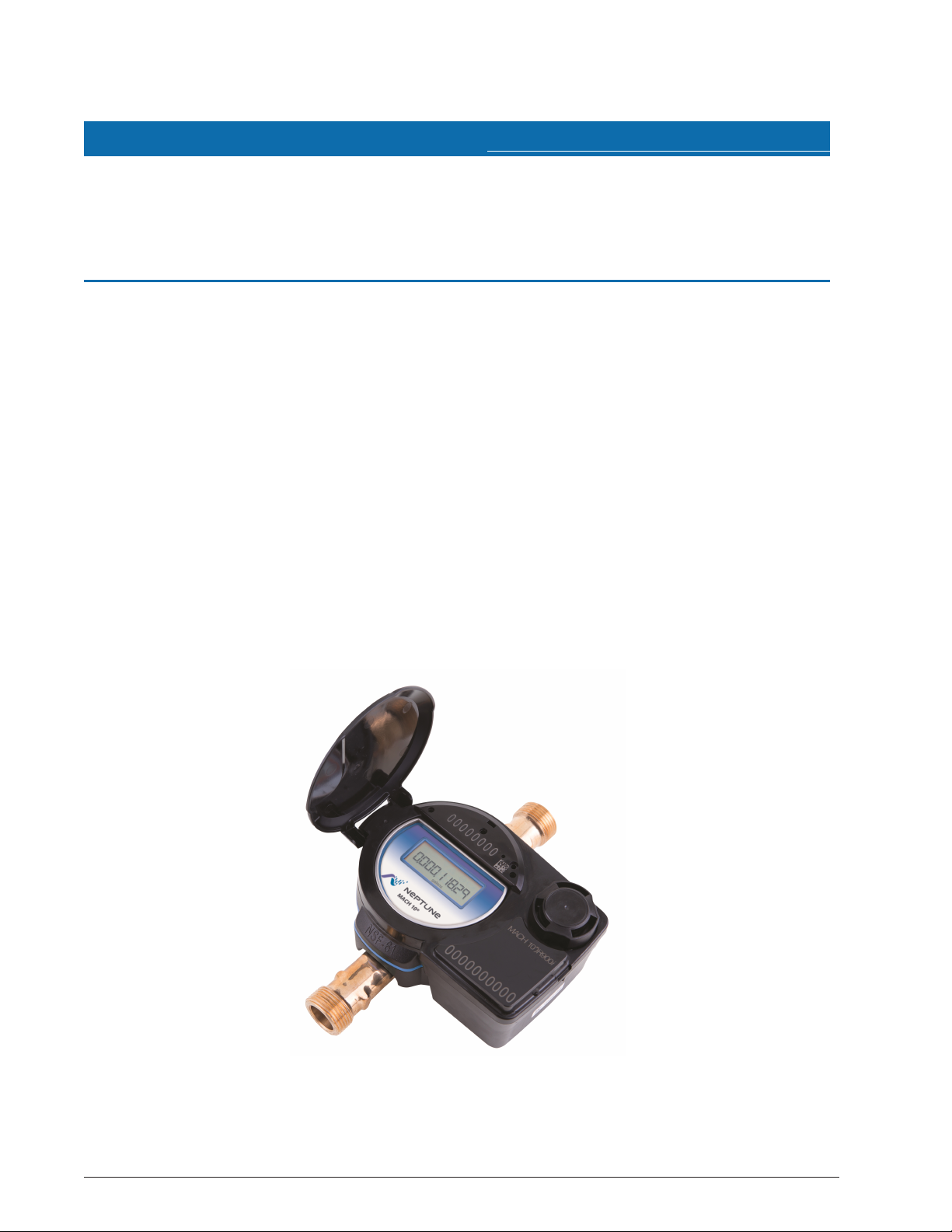
This chapter provides a general description of the Neptune®MACH 10®Ultrasonic Meter
(MACH 10).
The MACH 10 solid state meter uses ultrasonic transit-time technology and solid state
electronics. The meter is contained in a compact, totally encapsulated, weatherproof, and
ultraviolet (UV) resistant housing for residential and light commercial applications. Ultrasonic
technology features the following:
l Contains no moving parts
l Provides long-term accuracy
l Reduces measurement errors due to sand, suspended particles, and pressure fluctuations
The MACH 10 provides a Neptune E-CoderPLUS output signal to Neptune R900®and other
Automatic Meter Reading (AMR) / Advanced Metering Infrastructure (AMI)endpoints. The
MACH 10®)R900i™ contains a MACH 10 meter and an integrated R900 radio for
transmitting meter reading data. Consumption reflected is up to nine digits.
The meter electronics and battery are fully potted to eliminate the intrusion of moisture, dirt,
or other contaminants. It is suitable for installation in all environments including meter pits
subject to continuous flooding.
Figure 1 – MACH 10®Residential Ultrasonic Meter
MACH 10®Installation and Maintenance Guide 1
Page 16
Chapter 1: Product Description
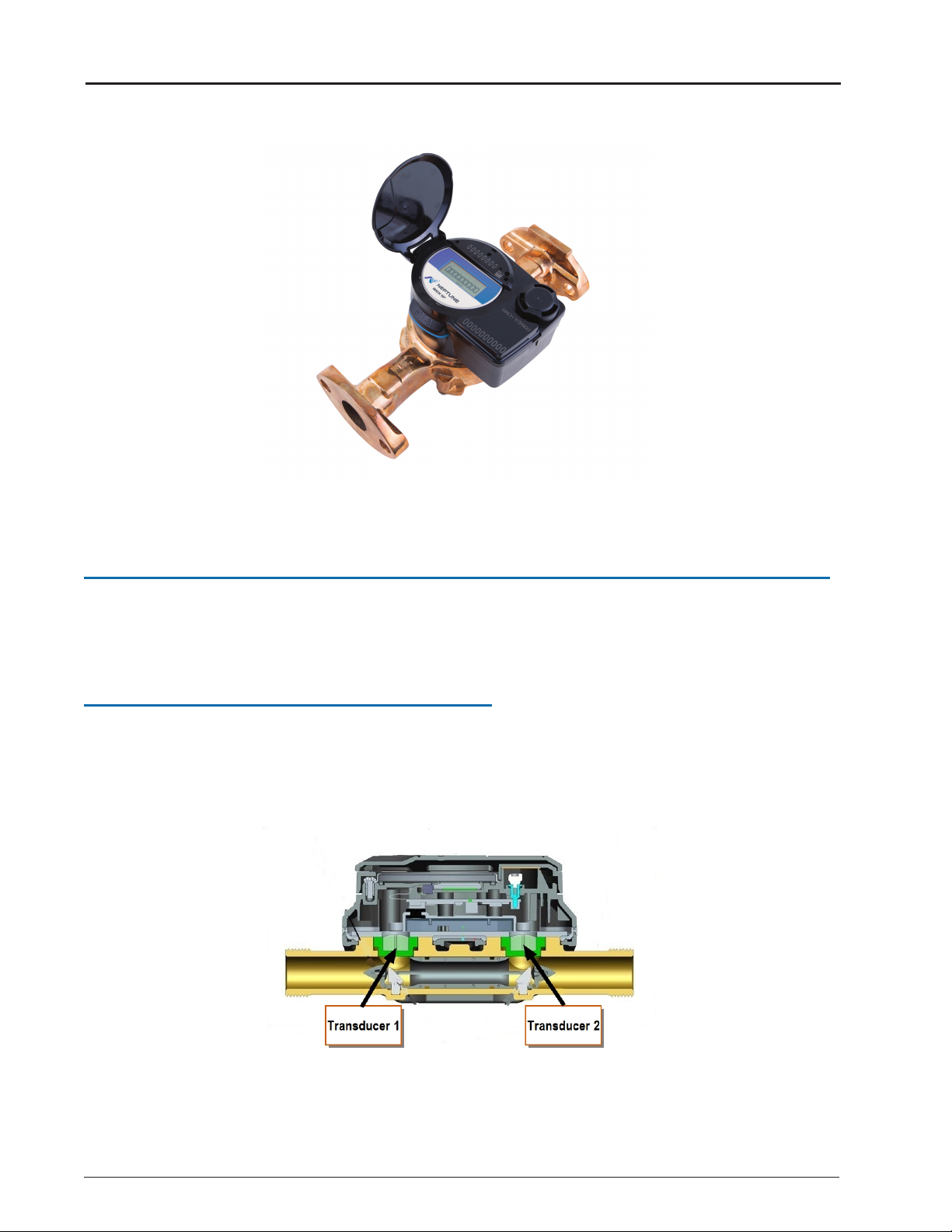
Figure 2 – MACH 10®Intermediate Ultrasonic Meter
Understanding Ultrasonic Technology
An ultrasonic water meter uses high-frequency sound waves to measure the velocity of an
acoustically-conductive fluid moving through it. The velocity of the fluid is then converted to
volume throughput using sophisticated algorithms and electronics.
Transit-Time Technology
The MACH 10 utilizes transit-time ultrasonic technology. This technology takes advantage of
the principle that an acoustic signal travels faster with the flow than against the flow of the
fluid. These meters have a pair of transducers that are essentially transceivers, sending and
receiving the acoustic signals.
Figure 3 – Transducers
2 MACH 10®Installation and Maintenance Guide
Page 17
Chapter 1: Product Description
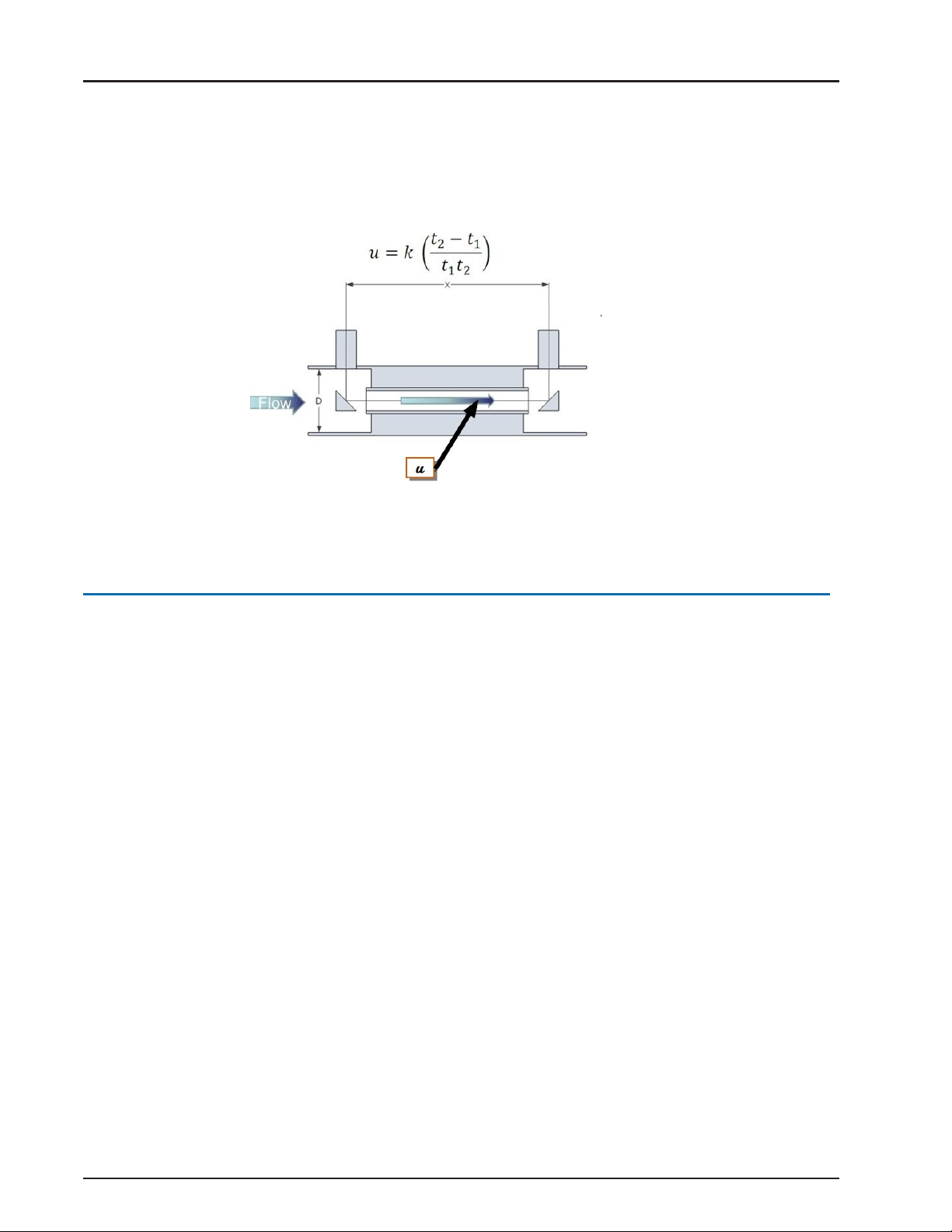
The difference between the downstream and upstream transit time—the time it takes for the
signal to travel from one transducer to the other—is proportional to the flow rate.
The calculated velocity of the water is then converted to volume based on the area of the
measurement section and by the algorithms and electronics in the register.
Figure 4 – Transducer - Calculated Velocity
Summary
The MACH 10 meter is a transit-time ultrasonic flow meter with wetted transducers. Designed
as an alternative for mechanical meters, the MACH 10 meter utilizes traditional utility pipe
connectors and lay lengths. It is totally self-contained. The battery, processor circuit, and
electronic display are fully potted and permanently sealed as an integral unit. The MACH 10
meter provides an E-CoderPLUS output signal to Neptune R900 and other AMR / AMI
endpoints. The MACH 10)R900i contains a MACH 10 meter and an integrated R900 radio for
transmitting meter reading data. See "MACH 10®)R900i™" on page27.
MACH 10®Installation and Maintenance Guide 3
Page 18

Chapter 1: Product Description
This page intentionally left blank.
4 MACH 10®Installation and Maintenance Guide
Page 19

Chapter 2: MACH 10®Specifications
Specification Description
Operating temperature 14° to 149° F (-10° to 65° C)
Storage temperature –40° to 158° F (–40° to 70° C)
Water temperature 33° to 122° F (0.5° to 50° C)
Operating humidity 0 to 100% condensing
Table 1 – Environmental Specifications
Meter Size
Normal Operating
Range @ 100%
Accuracy (± 1.5%)
AWWA C715
Standard Type 1
Extended Low Flow @
100% Accuracy (± 3%)
Residential
5/8" 0.10 to 25 U.S. gpm 0.2 to 20 U.S. gpm 0.05 U.S. gpm
3/4" 0.10 to 35 U.S. gpm 0.5 to 30 U.S. gpm 0.05 U.S. gpm
1" 0.40 to 55 U.S. gpm 0.75 to 50 U.S. gpm 0.25 U.S. gpm
Intermediate
1-1/2" 0.80 to 125 U.S. gpm
2.0 to 100 U.S gpm
0.30 U.S. gpm
2" 1.50 to 160 U.S. gpm 2.5 to 160 U.S. gpm 0.50 U.S. gpm
Table 2 – Performance Specifications
This chapter provides the specifications for the MACH 10®Ultrasonic Meter.
Environmental and Performance Specifications
This table defines environmental specifications that apply to both the Residential and
Intermediate MACH 10 meters.
This table defines performance specifications that apply to both the Residential and
Intermediate MACH 10 meters.
MACH 10®Installation and Maintenance Guide 5
Page 20

Meter Size Weight
Residential
5/8" 2.8 lbs
3/4" 2.9 lbs
1" 3.6 lbs
Intermediate
2" x 17" 15.6 lbs
1 1/2" x 13" 13.9 lbs
Chapter 2: MACH 10® Specifications
Weight and Dimension Specifications
The following tables define the weight and dimension specifications for the Residential and
Intermediate MACH 10 meters.
Table 3 – MACH 10
®
Meter Weight Specifications
The following tables define the meter dimensions as shown in the previous illustrations .
6 MACH 10®Installation and Maintenance Guide
Page 21

Meter Size A B C D NPSM
5/8" 7-1/2" 4-7/8" 2-1/2" 3/4" – 14
5/8" x 3/4" 7-1/2" 4-7/8" 2-1/2" 1" – 11-1/2
3/4" 9" 4-7/8" 2-9/16" 1" – 11-1/2
3/4" SL 7-1/2" 4-7/8" 2-9/16" 1" – 11-1/2
3/4" x 1" 9" 4-7/8" 2-9/16" 1-1/4" – 11-1/2
1" 10-3/4" 4-7/8" 2-11/16" 1-1/4" – 11-1/2
1" x 1-1/4" 10-3/4" 4-7/8" 2-11/16" 1-1/2" – 11-1/2
Meter Size Length Height Flanges
1-1/2" 10" 6-1/4" Oval
13" 6-1/4" Oval
12-5/8" 6-1/4" Internal thread
12-5/8" 6-1/4" External thread
2" 10" 6-1/2" Oval
15-1/4" 6-1/2" Oval
17" 6-1/2" Oval
15-1/4" 6-1/2" Internal thread
15-1/4" 6-1/2" External thread
Chapter 2: MACH 10
Table 4 – Residential MACH 10® Dimensions
Table 5 – Intermediate MACH 10® Dimensions
®
Specifications
MACH 10®Installation and Maintenance Guide 7
Page 22

Specification Description
Maximum operating pressure of
meter housing
175 psi (12 bar)
Register type Straight reading, permanently sealed electronic Liquid
Crystal Display (LCD); digits are 0.28" (7 mm) high
Register display l Consumption (up to nine digits)
l Rate of flow
l Alarms
l Unit of measure factory programmed for gallons, cubic
feet, or cubic meters
Battery 3.6 volt lithium thionyl-chloride; battery is fully encapsulated
within the register housing and is not replaceable
Table 6 – Additional Specifications
Chapter 2: MACH 10
®
Specifications
Additional Specifications
The following specifications are for the 5/8-inch through 2-inch Residential and Intermediate
meters.
Fluid Compatibility
The MACH 10 meter is designed and calibrated for potable, combination potable and fire
service, and reclaimed water across the defined temperature and velocity range.
Maincase
The meter maincase is manufactured using lead free bronze, and contains the wetted
elements of the meter: two transducers, pressed in reflections, and the flow conditioner.
Transducers
The piezoelectric transducer is the heart of the system. Although these transducers are very
small, they have very high measurement dynamics.
The signal path of the transducer utilizes two stainless steel reflectors. The transducers are
permanently installed and the path length and angles are fixed. Each meter is uniquely
calibrated at the factory and the calibration data is permanently stored in the meter.
8 MACH 10®Installation and Maintenance Guide
Page 23

Battery Requirement
Solid state metering technologies require a battery to power the transducers and electronics,
just like a radio Meter Interface Unit (MIU) requires a battery to perform its functions. With the
continued improvements made in battery technology, electronic metering utilizing internal
batteries is practical today. The MACH 10 uses lithium thionyl-chloride battery technology.
Chapter 2: MACH 10® Specifications
MACH 10®Installation and Maintenance Guide 9
Page 24

Chapter 2: MACH 10® Specifications
This page intentionally left blank.
10 MACH 10®Installation and Maintenance Guide
Page 25

This chapter describes tools, materials, and general installation information for the
Item Description / Recommendation Use
Tool Kit Contains standard tools including:
l Screwdrivers
l Pliers
Performing various installation
procedures
Flashlight N/A Activating the LCD
Magnet l 6 lb force
l Part No: 12287-0001
Activating the MIU
Table 7 – Recommended Tools
Item Description / Recommendation Use
Moisture Protection
Compound
Novaguard®sealant
Part No: 96018-072
Connecting the pit antenna to the
MIU
Site Work Order Documentation provided by your
utility
Receiving and recording
information about the work site
Table 8 – Recommended Materials
MACH 10®.
Tools and Materials
Table 7 and Table 8 show the recommended tools and materials you need to successfully
install the MACH 10.
Table 7 and Table 8 are not complete lists of tools and materials.
Chapter 3: General Installation Guidelines
MACH 10®Installation and Maintenance Guide 11
Page 26

Chapter 3: General Installation Guidelines
Safety and Preliminary Checks
Observe the following safety and preliminary checks before and during each installation.
l Verify that you are at the location specified on the site work order.
l Verify that the site is safe for you and your equipment.
l Notify the customer of your presence, and tell the customer that you need access to the
water meter.
l Write the ID numbers of the MACH 10 meters you are about to install on the site work
order. If the site work order already has a MACH 10 IDnumber, verify that it matches the ID
numbers on the MACH 10 you are about to install.
Installation and Application Considerations
This section provides information to consider before installing the MACH 10.
Water Temperature
The temperature range of the water is a factor in the selection of an ultrasonic meter, since
the meter is calibrated to operate within a specified range. The MACH 10 meter is calibrated
for water temperature (between 33° F and 122° F or 0.5° C and 50° C) measuring
applications.
Meter Installation
The MACH 10 meter can be installed using horizontal or vertical piping applications. The
meter features standard laying lengths for ease of retrofit of mechanical meters. A flow
direction arrow is visible on the top of the meter to aid in installation in the proper direction.
Water Flow
The MACH 10 meter is unable to measure flow when an empty pipe condition is detected. An
empty pipe is defined as a condition when the ultrasonic sensors are not fully wetted. In this
situation, the meter displays an alarm and no measurement occurs.
Meter Sizing and Selection
Traditional meter sizing methods apply to both electronic meters and mechanical meters.
That is, the maximum flow and maximum continuous flow rate requirements should be
considered when selecting a meter. Mechanical meters allow a temporary flow at a rate
higher than the maximum continuous flow. However, since electronic meters have no
moving parts, these two specifications are identical;the maximum flow rate is also the
maximum continuous flow rate.
12 MACH 10®Installation and Maintenance Guide
Page 27

Chapter 4: Installing MACH 10®Ultrasonic Meters
All MACH 10®ultrasonic meters are delivered activated and ready to be installed. When the
meter lid is opened, the meter shows the empty pipe icon and the latest volume on the LCD.
The empty pipe icon clears immediately after the condition is corrected and the pipe is full.
Installation Instructions for MACH 10®Meters
This section defines the step-by step instructions for installing the MACH 10 meter.
In outdoor settings, the meter and service line should be located deep enough in the
ground to prevent freezing.
New Meter Installation
The following are steps for installation of the MACH 10 meter.
1. Flush the service line prior to meter installation in order to remove debris in the line.
2. Place an electrical grounding strap on the service line, connecting the inlet and outlet
service lines on either side of the meter setting.
Install suitable inlet and outlet meter valves and couplings / setters if they are not already
present. Allow appropriate space in the line for the meter laying length and two coupling
gaskets. Align the pipe ends sufficiently so that the coupling and meter threads can engage
without binding or cross-threading.
3. Remove the thread protectors (if installed) before installing the meter.
Use caution; the meter threads are sharp.
4. Be sure that no debris enters the meter during installation.
5. Place the coupling gaskets, and set the meter in the line.
6. Start turning the coupling or flange nuts by hand, then using a wrench tighten sufficiently
to prevent leakage.
Be careful not to cross-thread the connections.
7. Open the upstream inlet valve.
MACH 10®Installation and Maintenance Guide 13
Page 28

Chapter 4: Installing MACH 10
8. Open the meter outlet valve slowly.
9. Open a downstream faucet, and run enough water to dissipate entrained air and flush
the line.
The Intermediate MACH 10 may take longer to completely remove air from the meter,
particularly when flow rates are less than 25% of the maximum flow rate of the meter.
10. Check to see if the meter is operating correctly, while the faucet is open.
11. Turn OFF the faucet, and check the meter installation for leaks.
®
Ultrasonic Meters
Wiring the MACH 10
The following table defines the steps to wire the MACH 10 meter while you are in the field.
If the meter is not a MACH 10 prewired and potted to an MIU, complete the following steps
to wire the MACH 10.
1. Hold the Scotchlok™ between the index finger and thumb with the red cap facing down.
2. Take one non-stripped black wire from the pigtail and one from the receptacle / MIU.
3. Insert the wires into the Scotchlok connector.
4. Insert the insulated color wires directly into the Scotchlok connector until fully seated.
®
Figure 5 – Scotchlok™ Connector
Figure 6 – Seat the Connector Wires
14 MACH 10®Installation and Maintenance Guide
Page 29

MIU Wire Color / MACH 10 Wire Color MIUType
Black/B Green/G Red/R
R900
Black/G Green/R Red/B Sensus
Black/B White/G Red/R Itron
Table 9 – Color Codes for Wires
Chapter 4: Installing MACH 10® Ultrasonic Meters
Do not strip the colored insulation from the wires, or strip and twist the bare wires before
inserting them into the connector. Insert the insulated colored wires directly into the
Scotchlok connector.
5. Place the connector red cap side down between the jaws of the UR crimping tool.
Figure 7 – URCrimping Tool
6. Check to ensure the wires are still fully seated in the connector before crimping the
connector.
7. Squeeze the connector firmly with the proper crimping tool until you hear a pop and the
gel leaks out the end of the connector.
8. Repeat steps 1 through 5 for each color wire.
Figure 8 – Improper Connections
MACH 10®Installation and Maintenance Guide 15
Page 30

MIU Wire Color / MACH 10 Wire Color MIUType
Black/G White/RRed/B Aclara
Black/G Green/B Red/R Elster
Black/G Green/R Red/B Badger
Table 9 – Color Codes for Wires (continued)
Chapter 4: Installing MACH 10® Ultrasonic Meters
Completing the Wiring
The following table outlines the steps to wire the MACH 10.
1. After you connect all three color wires, read the encoder register to ensure proper
connections and the receptacle / MIU is functioning properly.
Figure 9 – Three Colored Wires Connected
2. Take all three connected Scotchloks and push them into the splice tube until fully
enclosed by the silicone grease.
Figure 10 – Splice Tube
16 MACH 10®Installation and Maintenance Guide
Page 31

Chapter 4: Installing MACH 10® Ultrasonic Meters
3. Separate each gray wire and place them into the slots on each side.
Figure 11 – Gray Wires in Slot
4. Snap the cover closed to finish the installation.
Figure 12 – Cover in Place
MACH 10®Installation and Maintenance Guide 17
Page 32

Chapter 4: Installing MACH 10® Ultrasonic Meters
This page intentionally left blank.
18 MACH 10®Installation and Maintenance Guide
Page 33

Chapter 5: Activating and Reading MACH 10®Ultrasonic Meters
This chapter explains the operations of the MACH 10®ultrasonic meter.
Activating the LCD Meter Display
The light sensor is located in the center of the faceplate of the MACH 10, and it supplies the
power for the Liquid Crystal Display (LCD) panel.
Timeout Period
Typically, the display is OFF. The meter includes a light sensor used to activate the LCD when
you open the meter. A timed out LCD can not be reactivated just by shining a light on the light
sensor. In order to reset the meter, close and re-open the lid.
Meter Display
The Neptune MACH 10 ultrasonic meters use a nine-digit LCD to show consumption, flow
rate, and alarm information.
Figure 13 – MACH 10®Faceplate
MACH 10®Installation and Maintenance Guide 19
Page 34

Chapter 5: Activating and Reading MACH 10® Ultrasonic Meters
LCD Panel
Following is an example of the MACH 10 LCD panel. The table on the following page
provides a description of each icon.
The LCD can display commas or decimals, depending on the configuration of each register,
to show digits in the tens position, ones position, tenths position, and so forth. For
example, some registers display 1,234,567.89. Others display 123,456.789, 12,345,678.9,
or 1,234,567,89 depending on the need of the meter/register combination.
How to Read the Meter
It is important to become familiar with the information available from the meter. The icons
and displays provide helpful information.
Alarms
Indicators and alarms appear in the displays as symbols that illuminate when the condition is
active, and disappear when the alarm condition is eliminated.
Figure 14 – MACH 10®LCD Panel
20 MACH 10®Installation and Maintenance Guide
Page 35

Icon Description Status Explanation
Leak Icon used to indicate a leak. Leak
status is determined by keeping
track of the number of 15minute intervals where the
volume consumption exceeds
Vmin in the previous 24-hour
period. Vmin is factory
programmed depending on
meter size. It is defined as a
change of the ninth digit on the
LCD.
OFF Number of 15-minute intervals < 50.
Flashing 50 ≤ Number of 15-minute intervals < 95.
Continuous
ON
Number of 15-minute intervals ≥ 95.
Forward and
reverse flow
Icons used to indicate the
forward and reverse direction of
flow.
OFF No flow is detected.
Continuous
ON
The meter has detected flow.
High flow
warning
Icon used to indicate excessive
flow which can be a burst pipe.
OFF Rate of flow < Maximum defined by normal
flow range specifications.
ON Rate of flow exceeds normal operating flow
limits.
Empty pipe Icon used to indicate if the pipe
is empty or there is excessive
air in the line. If this occurs,
there is no receive signal in the
expected time window.
OFF Typically OFF. Meter is operating normally.
ON Turned ON if no receive signal is seen for
1 minute.
Battery status Icon used to indicate time and
voltage of remaining battery life.
OFF > One year of battery life remaining.
Time since first power ON < 19 years.
Continuous
ON
< One year of battery life remaining or time
since first power ON> 19.5 years.
Continuous
FLASHING
Low battery or time since first power ON >
20 years.
Chapter 5: Activating and Reading MACH 10® Ultrasonic Meters
LCD Icons
The following table defines the MACH 10 LCD icons and the status they indicate.
Table 10 – MACH 10® Icons and Displays
MACH 10®Installation and Maintenance Guide 21
Page 36

Capacity Display Resolution
Size Gallons Cubic Feet Cubic Meter Gallons Cubic Feet Cubic Meter
Residential
5/8" 10,000,000 1,000,000 100,000 0.01 0.001 0.0001
3/4" 10,000,000 1,000,000 100,000 0.01 0.001 0.0001
1" 10,000,000 1,000,000 100,000 0.01 0.001 0.0001
Intermediate
1" 100,000,000 10,000,000 1,000,000 0.1 0.01 0.001
2" 100,000,000 10,000,000 1,000,000 0.1 0.01 0.001
Table 11 – Consumption and Units of Measure
Chapter 5: Activating and Reading MACH 10® Ultrasonic Meters
Consumption and Unit of Measure
The consumption display contains all nine digits, including leading zeros and a decimal point.
The value displayed is the sum of the forward flow minus the reverse flow.
The unit of measure and resolution are factory programmed and options include gallons,
cubic feet, and cubic meters.
Rate of Flow
The rate of flow is factory programmed for either gallons per minute or liters per minute. The
LCD displays both the unit of measure and rate of flow. The rate of flow display also serves as
the flow finder indicator. The rate of flow display is shown without leading zeros. When rate
of flow is displayed, it is updated every two seconds.
Flow Direction
An arrow on the electronic register housing shows the direction of flow. Current flow
direction can be viewed on the LCD panel.
The direction of flow arrows on the LCD are activated when the meter detects any amount of
flow. If the volume of the flow is below a predetermined measurement threshold in a given
time period, the meter does not accumulate flow.
22 MACH 10®Installation and Maintenance Guide
Page 37

AMR / AMI Output
The Neptune MACH 10 ultrasonic meter is a compact design where the electronic register is
fully potted and permanently sealed to the meter maincase. The meter provides
high resolution E-CoderPLUS protocol. It communicates status indicators to Neptune R900
RF endpoints as part of the extended encoder / meter reading message. The meter also
provides ProRead™ protocol for third-party endpoints that are not capable of reading
E-CODER®eight digit or E-CoderPLUS protocol.
Endpoint Reading Resolution
The reading resolution sent to the reading software is dependent on the endpoint to which
the encoder is connected. Readings reported from the endpoints are the
left-most significant digits for the encoding reading.
Refer to "Wiring the MACH 10®" on page14 for wiring considerations.
Bench Testing the Meter
Chapter 5: Activating and Reading MACH 10® Ultrasonic Meters
Unlike other solid state meters introduced to the market, the Neptune MACH 10 ultrasonic
meter is designed to be bench tested as a traditional mechanical meter.
MACH 10®Installation and Maintenance Guide 23
Page 38

Chapter 5: Activating and Reading MACH 10® Ultrasonic Meters
This page intentionally left blank.
24 MACH 10®Installation and Maintenance Guide
Page 39

Chapter 6: Maintenance and Troubleshooting
This chapter provides information for maintaining and troubleshooting the MACH 10
meter.
Maintenance
Mechanical meters are subject to wear and are often rebuilt to extend their life. On the other
hand, the electronic MACH 10 meter does not have moving parts and requires no
maintenance. The meter enclosure, which contains electronics, transducers, battery, and
display is completely potted eliminating any maintenance. At the end of the meter's life, the
meter is simply replaced.
Replacement Parts
There are no replacement parts for the MACH 10 ultrasonic meter. If the plastic meter lid
becomes damaged or broken, it can be replaced.
Troubleshooting
Some conditions such as the following can occur.
l Battery is at low power.
l Meter starts sending colons.
l Communication stops.
®
Checklist
Before leaving the installation site, be sure to do the following.
Record the MIUID for each register.
Verify that you have followed all requirements of this Installation and Maintenance
Guide.
Verify that you have recorded all required information.
Clean up any installation debris.
Verify that the requirements of the Site Work Order have been completed.
Inform the customer that you have completed your work. If you were unable to finish,
inform the customer when you are returning to complete the project.
MACH 10®Installation and Maintenance Guide 25
Page 40

Chapter 6: Maintenance and Troubleshooting
Contact Information
Within North America, Neptune Customer Support is available Monday through Friday, 7:00
A.M. to 5:00 P.M.Central Standard Time, by telephone, email, or fax.
By Phone
To contact Neptune Customer Support by phone, complete the following steps.
1. Call (800) 647-4832.
2. Select one of the following options:
l 1 if you have a Technical Support Personal Identification Number (PIN)
l 2 if you do not have a Technical Support PIN
3. Enter the six-digit PIN and press #.
4. Select one of the following options.
l 2 for Technical Support
l 3 for maintenance contracts or renewals
l 4 for Return Material Authorization (RMA) for Canadian Accounts
By Fax
By Email
You are directed to the appropriate team of Customer Support Specialists. The specialists are
dedicated to you until the issue is resolved to your satisfaction. When you call, be prepared to
give the following information:
l Your name and utility or company name
l A description of what occurred and what you were doing at the time
l A description of any actions taken to correct the issue
To contact Neptune Customer Support by fax, send a description of your problem to (334)
283-7497. Please include on the fax cover sheet the best time of day for a customer support
specialist to contact you.
To contact Neptune Support by email send your message to support@neptunetg.com.
26 MACH 10®Installation and Maintenance Guide
Page 41

This appendix provides a general description of the MACH 10®)R900i™.
Product Description
The MACH 10®)R900i™ is manufactured by Neptune and is an integrated register that
contains both the MACH 10 meter and the R900®technologies in one register that collects
reading data. It then transmits the data for collection by the meter reader. A Neptune walk-by,
mobile, or R900®Gateway fixed network data collection system receives the data and stores
it to be downloaded into the utility billing system for processing.
The MACH 10 is easily installed and operates within a Radio Frequency (RF) band, which
does not require an operating license. The MACH 10®)R900i™ meets FCC regulations part
15.247 allowing higher output power and greater range. The MACH 10 uses frequency-
hopping spread spectrum (FHSS) technology to avoid RF interference and enhance security.
The transmitted data is updated at 15-minute intervals. It transmits a mobile message that
includes the meter reading data and the unique 10-digit MACH 10 ID every 14 to 20 seconds.
This allows the meter to be read by a hand held unit (HHU) or mobile data collection unit.
The MACH 10 also transmits a high power fixed network message every seven and one-half
minutes on an interleaved basis to an R900 Gateway.
Appendix A: MACH 10®)R900i™
The MACH 10 is designed to offer advantages to utility organizations of all sizes.
l Increases meter reading accuracy
l Eliminates hard-to-read meters
l Protects utility liability by increasing meter reader safety
l Requires no external wiring or programming
l Provides enhanced eight-digit AMRmeter reading
l Provides proactive customer service benefits (leak, tamper, and backflow detection)
MACH 10®)R900i™ Programming
The MACH 10 is not field-programmable. Each MIU is given a unique 10-digit serial number /
identification number.
RF Protocol Error Detection
The RF protocol is comprised of a header, data packet, and an error detection mechanism
that reduces the erroneous data.
MACH 10®Installation and Maintenance Guide 27
Page 42

Specification Description
Transmit Period l Every 14 to 20 seconds – standard mobile message
l Every 7-1/2 minutes – standards, high power, fixed network message
Transmitter Channels 50
Channel Frequency 910 to 920 MHz
Output Power Meeting FCC Part 15.247
FCC Verification Part 15.247
Table 12 – Transmitter Specifications
Condition Description
Operating temperature 14° to 149°F (–10° to +65°C)
Storage temperature –40° to 158°F (–40° to 70°C)
Operating humidity 0 to 100% condensing
Table 13 – Environmental Conditions
Specification Description
Register Reading l Eight digits (AMR)
l Nine digits (Visual)
MIUID 10 digits
Table 14 – Functional Specifications
Appendix A: MACH 10®)R900i™
MACH 10®)R900i™ Specifications
This section provides you with the specifications for the MACH 10®)R900i™.
Electrical Specification
Power is provided by a lithium thionyl-chloride battery.
Transmitter Specifications
The following table defines the specifications for the MACH 10 transmitter.
Environmental Conditions
The following table defines the optimal environmental conditions for the MACH 10.
Functional Specifications
The following table defines the functional specifications for the MACH 10.
28 MACH 10®Installation and Maintenance Guide
Page 43

Dimensions
Appendix A: MACH 10®)R900i™
The dimensions of the MACH 10 are shown in the following images and on page 30.
Figure 15 – MACH 10®)R900i™ Top View
Figure 16 – MACH 10®)R900i™ Side View
MACH 10®Installation and Maintenance Guide 29
Page 44

Meter A B C D NSPM
E
(external
antenna)
5/8" 7-1/2" 6-3/4" 2-1/2" 3/4" - 14 5-7/8"
5/8" x 3/4" 7-1/2" 6-3/4" 2-1/2" 1" - 11-1/2 5-7/8"
3/4" 9" 6-3/4" 2-9/16" 1" - 11-1/2 5-7/8"
3/4" SL 7-1/2" 6-3/4" 2-9/16" 1" - 11-1/2 5-7/8"
3/4" x 1" 9" 6-3/4" 2-9/16" 1-1/4" - 11-1/2 5-7/8"
1" 10-3/4" 6-3/4" 2-11/16" 1-1/4" - 11-1/2 5-7/8"
1" x 1-1/4" 10-3/4" 6-3/4" 2-11/16" 1-1/2" - 11-1/2 5-7/8"
Appendix A: MACH 10®)R900i™
The following tables define the dimensions of the Residential MACH 10 meters.
Table 15 – MACH 10®)R900i ™ Dimensions
30 MACH 10®Installation and Maintenance Guide
Page 45

Appendix B: MACH 10®)R900i™ Flags
Register Size
Eighth Digit Resolution -
Least Significant Digit
Residential
(5/8" - 1")
1/10 U.S Gallons or 1/100 Cubic feet
Intermediate (Light Commercial and Industrial)
(1-1/2" and 2"; 1-1/2" - 4" HPT)
1 U.S. Gallon or 1/10 Cubic feet
Table 16 – Eighth Digit Resolution by Meter Size
Backflow Flag (Resets After 35 Days)
Based on reverse movement of the eighth digit; eighth digit is variable
based on the meter size.
No backflow event Eighth digit reversed less than one digit
Minor backflow Eighth digit reversed more than one digit up to 100 times the eighth digit
Major backflow event Eighth digit reversed greater than 100 times the eighth digit
The three tables in this appendix describe the volume represented by the eighth digit by
meter size (Residential and Intermediate), and the flags used by the MACH 10®)R900i (digits)
and MACH 10®)R900i (minutes).
Table 17 – MACH 10®)R900i™ Flags (digits)
MACH 10®Installation and Maintenance Guide 31
Page 46

Leak Status Flag (Resets After 35 Days)
Based on total amount of 15-minute periods recorded in the previous 24-hour period.
Leak icon off Eighth digit incremented less than 50 of the 96 15-minute intervals
Flashing leak icon Eighth digit incremented in 50-95 of the 96 15-minute intervals
Solid leak icon Eighth digit incremented in all of the 96 15-minute intervals
Consecutive Days with Zero Consumption Flag (Resets After 35 Days)
Number of days the leak status was at a minimum value
Appendix B: MACH 10®)R900i™ Flags
Table 18 – MACH 10®)R900i™ Flags (minutes)
32 MACH 10®Installation and Maintenance Guide
Page 47

A
AMI
Advanced Metering Infrastructure. A system that captures, stores, and provides to the utility at
frequent intervals detailed consumption and other information, such as, usage, leak, and flow
status, to support advanced applications.
AMR
Automated or Automatic Meter Reading.
E
empty pipe
Condition whenever the measurement section of the meter is not completely filled with water.
Glossary
L
LCD
Liquid Crystal Display.
light sensor
Component located under the recess that is used to activate the Liquid Crystal Display (LCD).
M
MIU
Meter Interface Unit.
MACH 10®Installation and Maintenance Guide 33
Page 48

Glossary
S
serial number
Unique identification number given to each meter at the factory. The default value is the last
programmed plus one. Custom serial numbers are not available.
T
transceiver
Device that transmits and receives communications, in particular a combined radio transmitter
and receiver.
transducer
Device that converts one form of energy to another form of energy.
transit-time
Technology that takes advantage of the principle that an acoustic signal travels faster with the
flow than against the flow.
U
ultrasonic flow
Use of ultransonic technology to measure the velocity of an acoustically conductive liquid or gas
moving through it. The velocity of the water is then converted to volume throughput using
sophisticated algorithms and electronics.
ultrasonic meter
Electronic meter using ultrasonic technology and solid state electronics contained in a compact,
totally encapsulated, weatherproof, and ultraviolet (UV) resistant housing for residential and
light commercial applications.
34 MACH 10®Installation and Maintenance Guide
Page 49

V
Vmin
Change the ninth digit of the LCD. This is factory programmed depending on meter size.
Glossary
MACH 10®Installation and Maintenance Guide 35
Page 50

Glossary
This page intentionally left blank.
36 MACH 10®Installation and Maintenance Guide
Page 51

contaminants 1
Index
A
acoustic signal 2
acoustically 2
activating 19
LCD 11
alarm 12, 20
algorithms 2
AMI 1, 3
AMR 1
B
backflow 31
battery 1, 25
coupling gasket 13
crimping tool 15
cross-thread 13
customer support 26
D
debris 13
E
E-CoderPLUS 1
F
faucet 14
fire service 8
requirements 9
bench testing 23
C
calculated velocity 3
calibrated 12
checks
preliminary 12
safety 12
conductive 2
connections 16
consumption 19, 22
fixed network 27
flags 31
flashlight 11
flow
direction 22
rate 12
G
grounding strap 13
H
hopping, frequency 27
MACH 10®Installation and Maintenance Guide
37
Page 52

Index
I
icon
battery status 21
empty pipe 21
forward and reverse flow 21
high flow warning 21
leak 21
installation
guidelines 11
meter 12-13
installing 13
integrated 3
L
transmitter 28
maincase 8
maintenance 25
meter
bench testing 23
display 19
sizing 12
threads 13
N
Novaguard sealant 11
O
operating license 27
Other Term
LCD 19
panel 20
leakage 13
light sensor 19
M
MACH 10® 1
R900i 27
flags 31
programming 27
specifications 28
dimensions 29
electrical 28
functional 28
Subterm 8, 21, 28
output 23
P
piezoelectric 8
piping 12
potted 3, 23
product description 1
R
rate of flow 22
reading resolution 23
recommended
materials 11
38 MACH 10®Installation and Maintenance Guide
Page 53

Index
tools 11
reflectors 8
register
display 5
type 5
resolution 22
retrofit 12
RF
band 27
protocol error 27
S
sealed 3
service line 13
velocity range 8
W
water flow 12
wetted 8
wrench 13
T
temperature
water 12
Term SeeOther Term, Subterm
toolkit 11
transceivers 2
transducers 2, 8
transit-time 2
troubleshooting 25
V
valve 13
inlet 13
outlet 14
MACH 10®Installation and Maintenance Guide 39
Page 54

Page 55

IM MACH 10®12.18 Part No. 13682-001© Copyright 2003-2018,
Neptune Technology GroupInc. Neptune is a registered trademark of
Neptune Technology GroupInc.
 Loading...