

Page 1
OPERATING &
Models G-50-1, G-50-1A, G-50-2A, G-100-1A, G-100-2A
Lansdale, PA 19446 Tel: 215-699-8700 Fax: 215-699-0370
REV NO 6 – 01/08/04
ZL106838
INSTRUCTION
MANUAL
NEPTUNE
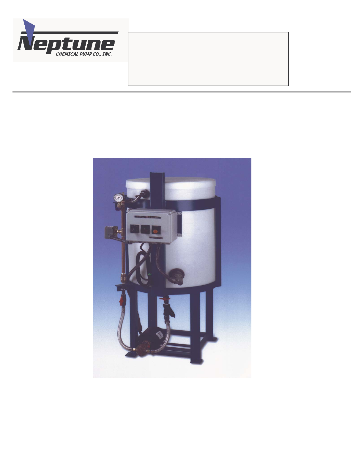
GLYCOL FEED SYSTEM
Page 2

I.
GENERAL DESCRIPTION
Neptune Chemical Pump Company’s Glycol Feed System is intended for the automated
addition of glycol into closed loop chille d and hot water syste ms. The Glyco l Feed System
automatically maintains pressure in the loop by adding glycol solution to make up for
losses, which occur due to leakage.
Glycol addition is controlled by a pressure switch with adjustable low and high set points.
When the pressure in the loop reaches the low set point, the pump begins to feed glycol
into the system until the high set point pressure is achieved and stops the pump.
I.
MODELS
The Model G-50-1 or G-100-1 is provided with a 50 or 100 gallon polyethylene tank
mounted in a steel frame, 1.5 gpm bronze rotary gear pump (optional 3.0 gpm pump), float
switch and NEMA 4X control panel. The control panel features a HAND/OFF/AUTO
selector switch for the pump motor, ON indication light for the pump, LOW tank level
indication light and power cord with plug (115V, 60c). The pump suction piping includes
a PVC ball valve and cast iron “Y” strainer. The pump discharge assembly includes a PVC
ball valve, brass check valve, pressure switch, bronze relief valve and pressure gauge.
The Model G-XX-1A is identical to the G-XX-1 and has the addition of an audible
alarm, as well as light for low level tank indication.
The Model G-XX-2A is capable of feeding glycol to two separate closed loop systems
and includes two separate pumps, as well as suction and discharge assemblies.
The LP designation at the end of a model number (ex. G-XX-1-LP) indicates that a 3.0
gpm pump has been provided in place of our standard 1.5 gpm pump.
All glycol systems are provided with a dry contact for remote alarm.
Page 3

II.
OPERATION
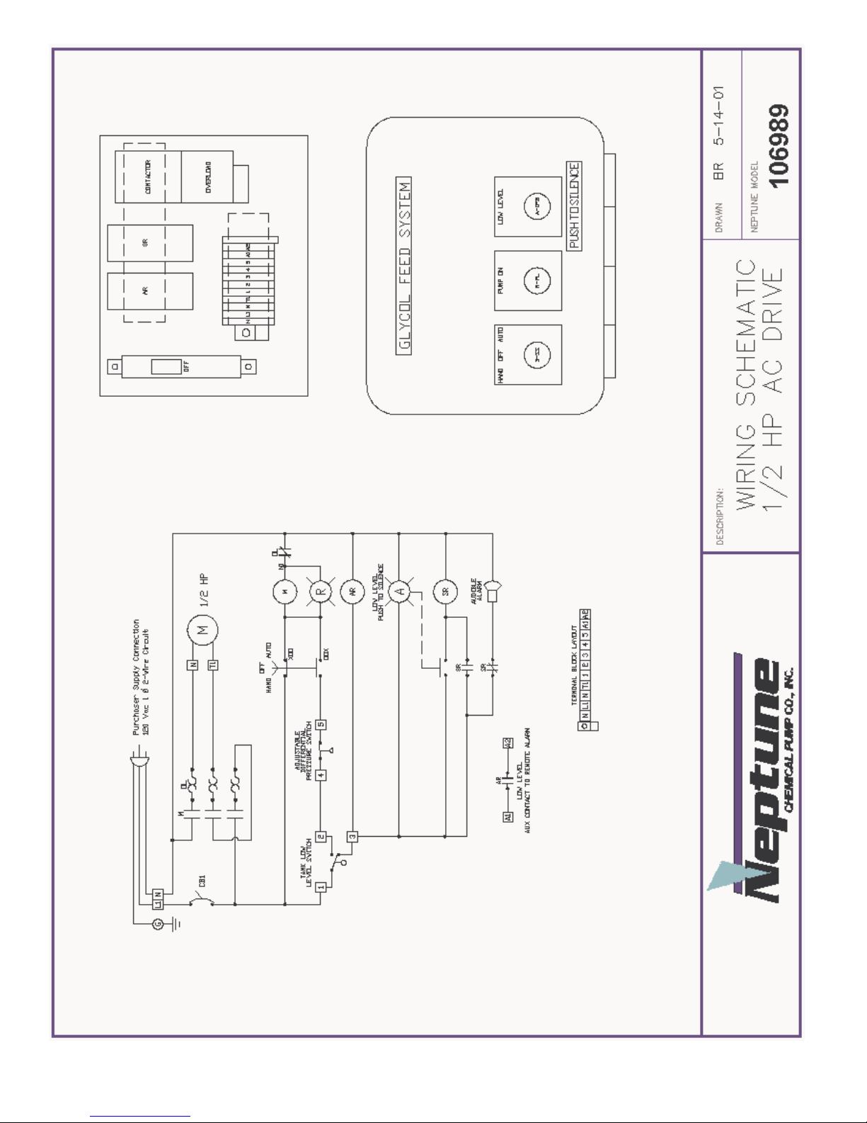
The glycol feeder is provided with a control panel with HAND/OFF/AUTO selector
switch.
When the panel is switched to the AUTO position, the pump is actuated via the pressure
switch, which is mounted in the discharge assembly and sensing the pressure in the loop.
The pressure switch is pre-set to start the pump at 12 psi and stop the pump when 30 psi in
the loop is achieved. The adjustment range for the standard pressure switch is 10-45 psi to
start the pump and 20-60 psi to stop the pump. The minimum differential pressure
between the cut in and cut out set points is 10 psi and the maximum is 30 psi. The float
switch in the bottom of the ta nk will stop t he pump if the glyc ol solution in the tank gets to
low leve l.
The MANUAL position of the selector switch in the panel will allow the pumps to run and
inactivate both the pressure switch and the level switch.
PLEASE READ THIS
The initial settin g of the pre ss ur e swit ch is crit ica l
to the proper operation of the glycol feeder.
The pressure relief valve is factory set at 60 psi.
DO NOT operate the glycol feeder above 100 psi.
If your application requires a higher operating
pressure, consult the factory.
WARNING
Page 4

TROUBLESHOOTING
PROBLEM
PROBABLE CAUSE
Pump is running but is 1. The motor rotation is incorrect. The
not pumping anything proper rotation of the motor is counter-clockwise when
looking at the motor shaft. Check the wiring diagram
on the motor or t he a tta ched motor diagram for prop e r
wiring.
2. On simplex single pump systems – Model G-XX-1 and
G-XX-1A. The motor should be wired for 115V
counter-clockwise rotation. See further information on
the pump, which is attached.
3. Duplex or two pump systems, Model G-XX-2A, require
one pump motor to be wired counter-clockwise and the
other in a clockwise rotation. Looking at the front of
the Model G-XX-2A, the control panel facing you, the
pump motor on the left should be wired counterclockwise and the pump motor on the right should be
wired for a clockwise rotation.
Pump is not running when 1. The low level float switch may be
HOA switch is in the AUTO actuated. The low light will be on a nd
position the audible alarm will sound on some
models. Add glycol to the tank until
the leve l s w it c h is sa tisf ie d.
2. The pressure switch in the discharge piping has been
satisfied. The press u re s w itch is factory set to ac tuate
the pump at 12 psi and shut-off at 30 psi. See pressure
switch information for pressure switch adjustment,
which can be found on the inside cover of the pressure
switch.
Page 5
Page 6

Page 7

Page 8

Bronze Rotary Gear Pumps
Installation, Operation, and Maintenance Instruction
INTRODUCTION
Congratulations for choosing an Oberdorfer pump,the Industry Standard for quality since 1890.
Construction
Bronze Rotary Gear stan dard pump hou sings and h elical gears are made of top q u ality bronze. Shafts ar e st ainless steel. Pump s are availab le
with br on ze bearings and gr ease fittings or with carbon bea r ings whi ch require n o lu brication. Dynamic seal arr angem en ts inclu d e packing,
lip, or mechanical seal s for a variety of ap plicat ion requirement s. S tatic cover o- r ing seal s eli minate g asket probl ems.
Application Range
Bronze Rotary Gear pump s are of the ext ernal gear positive displacement t ype, d isplacing a fini te volume of flu id with each shaft revolution.
As such, capaci ty varies in direct pr op ortion t o p um p sp eed . They are s u ited to han d le clear lubricat in g an d n on-lubricating fl ui ds, with PH
ranging from 4 to 11, and temperatures to 400F. These pumps handle viscous fluids to 100,000 cps (462000 SSU) at reduced shaft speeds, with
flow rates to 175 GPM (662 LPM), differential pressures to 150 psig (10.3 BAR), and suction lift capability to 20 feet (6.1 meters ) for new
pumps.
Field Inspection
Bronze Rotary Gear pum ps may be rea dily insp ec ted in the field usually without re moval from the dr ive or s ystem p lumbing. S imply rem ove
the cover screws to pull the cover. Before attempting an inspection, follow safety precautions and be sure to read and understand this
manual.
New Pump Receipt Inspection
Upon r ecei pt, check for obvious s hipping damage and complet eness to p urchase order requ irements. Shorta g es or d amage shoul d be reported
immediately to the carrier and to your Oberdorfer distributor. Occasionally during shipment, possible misalignment or other damage
inclu ding cra cked mechan ical sea l fa ces can occur . As such, cust om ers ar e ad vi s ed to test th e pump with water in a conven ient location prior
to installin g in to the intended s ystem .
Storage
If the pump is to be stored prior to installation, it is recommended that it be left in the original shipping carton with all shipping plugs in
place an d stored in a dry environment avoid ing temperatur e variati ons. Contact the mot or manufacturer for s p ecific motor s t or age
informa tion .
Records
These instru ctions sh ould be kept in a convenient locat ion for ready r eference. The man ua l should be read carefu lly by pers ons responsible
for installation, operation, and maintenance of the equipment. For ease of reference, a copy of the order should be kept with the manual.
Write d own the pump model number as shown on the pump nam etag, and th e date the uni t wa s placed into service.
Page 9

BRONZE ROTARY GEAR PUMP INSTRUCTIONS continued …….
INSTALLATION
Site Preparatio n
Choose a site that a llows easy acces s t o the pum p for mainten ance. Con s i der prot ect ion from th e element s. Guard against drip s and spray
from nearby equipment. Ch oos e a sol id founda tion for mounting. If noi s e is a concern, consider a rubber pad under the pum p base to
dampen.
Flow Direction
Gear pumps will perform equally wel l in eith e r dir ec tion howeve r care mu s t be tak en for pump s equipped wi th in tegr a l pressure relief valves.
To change flow direction effectively reversing the suction and discharge ports, simply switch driver rotation by following motor wiring
diagram instructions and change the location of the relief valve as shown below. Most pump motor units are factory supplied with
counterclockwise shaft rotation (when viewing the pump from the shaft end).
Suction Plumbing
Suction side plumbing considerations are key to desirable pump performance. Minimize head loss by assuring sufficient pipe size (especia lly
important for highly viscous services). Generally the same size pipe as the pump ports is adequate. For long runs (beyond 3 feet) or visc ou s
fluids, use one or two pipe sizes larger. Strive to keep the lines as short and straight as possible. If flexible lines are used, they shoul d be
selected to prevent wall col lapse. To keep th e pum p fr om bei ng starved or running dry, be sure there is s u fficient fl u id supply. A flooded
suction is generally preferred . S uctio n l ifts over 3 vert i cal feet and l ong hor izontal ru ns (bey ond 3 l ineal fee t ) req uire a foot or check valve
below the level of the liquid being pumped. When taking suction from a tank or vessel, position the inlet above the maximum expected level
of solids. Use full-bore ball valves or gate valves to minimize restriction. Suction strainers should be properly sized to minimize press ure
drop and positioned for easy cleaning access. If st ar t-up scr eens are used , be su re they ar e r emoved prior to pla cin g the system in to regular
operation. Orient lines so as to prevent formation of air pockets. Be sure all joints are tight. Flush out all suction lines prior to installing the
pump.
General Piping
For further eas e of m aintenance, use union fittings t o connect the pump to the s ystem. In stall a di s ch ar g e pr iming tee for conven ience. D o not
spring the piping to connect the pump. Use piping supports or hangers as required. When necessary, provide for thermal expansion and
contraction to avoid placing strain on the pump.
Alignment
Proper alignmen t is key to seal an d bearin g p er forman ce. Improp er alignment can lea d t o premature pump failure. Ch eck th e alignment
carefu lly between the p um p an d th e dr ive.
Belt Drive
Though alignment is not as critical as direct connected, ensure that the pump and motor shafts are parallel and in line. For units suitable for
belt drive, be sure that the belt tension is adequate (per the belt manufacturer’s recommendation) but do not overtighten. For heavy pulley
loads, models are equipped with external ball bearing supports. A single 1/2” (A or 4L section) V-belt is satisfactory for drive speeds up to 1
HP 3450 RPM. For larger drive sizes, double-V belts are recommended. Install guards around all moving parts in accordance with OSHA to
prevent per son al injury.
Fasteners
Unless the pump has been shipped directly from the factory, it is recommended to check all bolts and nuts for tight-ness to eliminate pos s ib le
lea kag e problems or destructive vibration.
Pressure Relief
Discharge lines should be fitted with properly sized line pressure relief valves to protect both the pump and the system. Pumps equipped with
integral internal bypass relief valves are intended as a safety device against intermittent overpressurization. They are not designed for
continuous us e an d can lead to overheatin g . In these in st ances, a line press ure reli ef va l ve is required. The r elief outlet should be piped back
to the suction vessel.
Page 10

BRONZE ROTARY GEAR PUMP INSTRUCTIONS continued …….
Flow By-Pass
When a flow b y-pa s s syst e m is used t o c ontrol ou tput from th e pump, the bypa ssed fluid shoul d be direct e d back to t he suc tion vessel to
avoid recirculation heat build-up. In cases where this is not possible, connect to the suction at least 10 pipe diameters length away from the
pump inlet. Provisions for cooling should be made in the event of recirculation heat build-up.
Pump Driver Mounting
Adapter kits (including bracket, coupling components, and hardware) are available for Bronze Close Coupled Gear pumps allowing
conn ectivit y to NE MA an d IEC motor fra mes. Assem bly instructions are included with each kit. A da p terless mot ors, car bon ator mounts, and
electric clut ches are a va il able for som e models. Base mount ki t s (includin g ba sep late, cou p ling comp onents, coup ling guard, and hardware )
are ava ilable for Bronze Ped es tal Gear p um p s . C on t act your Ober d orfer rep resent ative for a d ditional informa tion.
OPERATION
Pre-Startup
Prior to start-up, recheck installation as described above. Verify desired rotation by jogging the motor and make corrections if necessary.
Before initia l s tartup, pre-wet the gears an d ma k e s ure the pump is ad eq u ately primed. Failure t o do so could cau se immediat e damage to
pump comp onents. M ake sure tha t d ischar g e val ves a re open.
Startup
Start pump and check for proper operation. Adjust packing (if applicable) as necessary, allowing adequate time to run in. Do not overtighten
the packing el s e da mage to the pa cking and th e shaft can occur. A proper ly packed and adju sted packing nut will leak at abou t 10 drops
every 3 to 5 minutes. Tighten packing nut only while shaft is rotating. Lip and mechanical seal versions require no adjustment. If the pump’s
bearing areas or seal area runs hot, shut the pump down and determine the cause. For units equipped with integral pressure relief valve, th e
factory settin g is usual ly 50 psig. It is recommended that the setting shou l d be 5 p s ig abo ve t he oper ating pr ess ure in the discharge line. To
incr ease the set p oint, turn th e b y-pass val ve a d ju s ting s cr ew cl ockwise. If start-up screens were u s ed , be sure they are remo ved prior to
placing the system into regular operation. Depending on suction conditions, it may be necessary to reprime the pump for subsequent restarts.
MAINTENANCE
Frequency
Since each installation differs, the frequency and extent of pump maintenance is best established based upon past performance. Keeping
detailed main tenance records of past per formance aids in determin in g futur e preventa tive main tenance intervals. During routi ne operating
inspections, pay particular attention to seal and bearing areas of the pump. Consult the motor manufacturer for motor maintenance
instructions.
Changing Applications
Verify that all wetted parts of the pump are compatible with the new fluid to be handled and that the motor is adequately sized. Check with
your Oberdorfer distributor if in doubt.
Inspect for Wear
If you r Bronz e Gear Pump exhibi ts reduced flow, an inabi lity to maintain pre s s ure, is noisy or per forms ot her wise abnormally, first refer to
the T roubleshooting M a trix on back . If th e probl em persis ts, th e pump shoul d be i nsp e cted for wear or damage. Oberdorfe r Bronze Gear
pump int erna ls may be rea dily insp e c ted in the fi e ld u s ually without removal fr om th e drive or syst e m pl umbin g. Sim ply r e move the cover
screws to pull the cover. Full pump removal and complete disassembly may be needed for a comprehensive inspection. Contact your local
authorized d istributor or th e O berdorfer fa ctory.
BRONZE ROTARY GEAR PUMP INSTRUCTIONS continued …….
Page 11

Mechanical Seals
Pumps eq u ip p ed with mech anical seals are of the standard pusher bellows type or wedge style. Th ey can be expected to provi d e long and
trouble free se rvi ce provided :
1) Seal materials are compatible with pumped fluid and properly applied to the service.
2) Adequate cooling and lubrication is provided
3) Dry running is avoided
4) Abra sives are kept away from the seal ar ea
5) Pump an d dr iver are pr operly aligned
Detai led mechanical s eal inspect ion and rep lacement instr u ctions are included with Ober d orfer Repair Kits.
Lip Seals
Pumps eq u ip p ed with lip seals are of the metal cased, spr in g energized, sing le lip style. These ar e in tended to provide min i mum friction drag
with positive sealing and again should be maintenance free provided the same conditions for mechanical seals are met as well as:
6) Avoid s courin g of the shaft in the lip sea l area due to contamin ated abrasives
7) Avoid excessive seal lip contact pressure on the pump shaft due to excessive pump pressure.
These are rea di ly replaceable by pres s i ng out the old seal and pressing in a new r ep lacement .
Packing
Pumps equipped with teflon or graphoil packing require periodic adjustment as described above in the Startup section to avoid excessive
leakage. Eventually all the packing in the pump will become deteriorated and will have to be replaced.
Recommended Spares
Repair k its are ava ilable for all Oberdorfer Bron ze Gear Pump s. Each ki t com es with det ailed ins tr u ctions. F or the proper kit, contact your
Oberdorfer Di s tr ibutor or th e fa ctory.
Page 12

PRESSURE SWITCH INSTRUCTIONS
SQUARE D
Commercial Pressure Switch
Class 9013, Model FSG29J99
Model FSG29J99
CUT-OUT RANGE 20-60 PSI
ADJUSTABLE RANGE 10-30 PSI
CUT-IN RANGE 10-45 PSI
PRESSURE CONNECTION : ¼” NPT EXTERNAL
ECHNICAL TERMS
T
Operating Points ( S et ting s)
Every pressure swit c h has two operating points; one on risi ng pr essure and one of falling pressure. The operat ing point on rising
pressure is refer r ed to as the TRIP POINT or cut out for pumps and compressors and the operating point on falli ng pressure i s
referred to as the RESET POI NT or c ut in f or pumps and compressor s. These operating points are called the SETTINGS of the
switch.
— TRIP POINT (rising pressure )
— RESET POINT (falling press u re)
Differential
The differenti al is the difference in pressure between the trip point (cut-out) and the reset point (cut-in). It can be adjusta ble or
nonadjustable (f ixed).
Example: Cut-in 30 psi
Range
The range is the pressure lim its within which the operating points (settings) can be adjusted. The range of the Class 9013
pressure switch is referenced to the operating point on rising pressure (trip point). The differenti al subtr ac ts from the trip point
setting. During the normal operating cycle, system pressure should nev er ex c eed the upper lim it of the range when using a
diaphragm actuated switch. This will greatly r educ e the life of the diaphragm.
Maximu m Allowable Pressure
Maximum allowable pr essure is the pr es sure t o whic h a switc h c an be subj ec ted without causing a c hange in operating
characteri stic s, shift in settings, or dam age to t he dev ice. P r essure surges may occur in a system duri ng the start up of a
machine or from valv e operation. Surges are not normally detrimental to the life of a switch if t he surge is within the maximum
allowable pressure rating of the switch. Di aphr agm actuated switches should not be subjected t o more than 10 surges per day.
More frequent surges will greatly reduce the lif e of t he diaphr agm .
Cut-out 50 psi
Differential 20 psi (50-30 psi)
Page 13

PRESSURE SWITCH INSTRUCTIONS continued …..
SET POINT ADJUSTMENTS
The pressure switch is set at the factory to the operati ng point(s) marked on the outside of the switc h housi ng. Before
readjusting t he switc h, cyle it to determine act ual oper ating points.
Non-Adjustable Differential
The range adjustment nut ( Item H, Figure 3 ) or knob ( Item C, Figure 3 ) adjusts both setpoints by t he same amount.
To adjust the operating points :
1. Place a flat blade screwdriver in a range adjustment nut slot.
2. Rotate the nut to the left t o inc r ease the oper ating points or to the right to dec r ease t he oper at ing set points.
Adjustable Differential
The range adjustment nut or knob determines the decreasing setpoi nt. The adjusti ng screw ( Item J, Figure 3 ) determines the
increasing setpoi nts. To adjust the operati ng points :
1. Adjust the decreasi ng setpoint ( see steps 1 and 2 above ).
2. Turn the adjusting scr ew cl oc k wise ( t o r aise the increasing setpoint ). This adjustment does not aff ect the
decreasing setpoint.
FIGURE 3
Page 14

INSTALLATION INSTRUCTIONS LL-3 (L-30N)
LIQUID LEVEL SWITCH
MODEL L30N LIQUID LEVEL SWITCH
INSTALLATION AND OPERATING INSTRUCTIONS
Installation:
The L-30 liquid level switch is supplied with a 1-1/2” or 1-1/4” X 1 bushing threaded in place
with 2 to 3 wraps of teflon tape, which must be intact or renewed if bushing and switch are
separated before assembly in tank. Care must be exercised when threading the bushing
into plastic or metal fittings. Apply a minimurn of 2 to a maximum of 3 wraps of teflon tape
to threads of bushing - this is especially important if unit is to be used in metal fittings where
coarse
METAL THREADS could gall plastic if not lubricated. The plastic bushing CAN BE
CRACKED if the main body of the flow switch is tightened into it FIRST. Cracking will not
occur if the bushing is FIRST tightened into the pipe or tank fitting and THEN the L-30 body
is tightened into the bushing.
Thus:
1). Teflon tape thread and tighten plastic bushing into pipe or tank fitting.
2). Teflon tape thread and tighten L-30 switch into PLASTIC bushing by applying wrench to
hexagon section. Repeat steps I and 2 until ARROW on
body points to UPWARD and
threads are, leak tight.
Plumbers'tools such as pipe wrenc hes are not recom m en de d. If possibl e us e a "Ridgi d"
typ e wrench where the smooth jaws closely fit the hexagon section.
Electrical Wiring:
1). Remove gland nut, grommet and switch cover.
2). Strip outerjacket of electrical cord back
3). Slip on terminals are
individual conductors supplied with each switch. approximately 1-1/4". Strip insulation
from back approximately 1/4". Remove from switch terminals and
and crimp on or solder to electrical leads.
4). Feed electrical cable throu gh gla nd nut, gr om m et and s witch cov er as sho wn.
Page 15

MODEL L30N LIQUID LEVEL SWITCH
INSTALLATION AND OPERATING INSTRUCTIONS
5). Apply slip on terminals to appropriate contacts of micro switch. Slide cover down
cable and fasten to body of switch with four screws provided. Slide grommet down cable
until outer jacket is level with small end of grommet per illustration page 2. Push
grommet into tapered end of cover. Hold cable jacket to prevent rotation and thread
gland nut firmly on to cover.
Fig. 1: Wiring schematic for power applied to load when liquid level is less than set point
(power to load inter ru pte d when l evel increa ses to ab ove set point).
Fig. 2: Wiring schematic for power applied to load when liquid level is greater than set
point (power to load interrupted when level decreases to below set point).
Figure 1 Figure 2
Microswitch actuation point may be monitored by an audible click or with an OHM meter
before connecting line power to the terminal strip or by monitoring the voltage supplied to
the load through the microswitch.
 Loading...