

Page 1
P
.O. Box 247 • Lansdale, PA 19446-0247
Tel: 215-699-8700 • Fax: 215-699-0370
Toll-Free Tel: 1-888-3NEPTUNE (1-888-363-7886)
T
oll-Free Fax: 1-800-255-4017
W
eb Site: http:// www.neptune1.com
E-mail: pump@neptune1.com
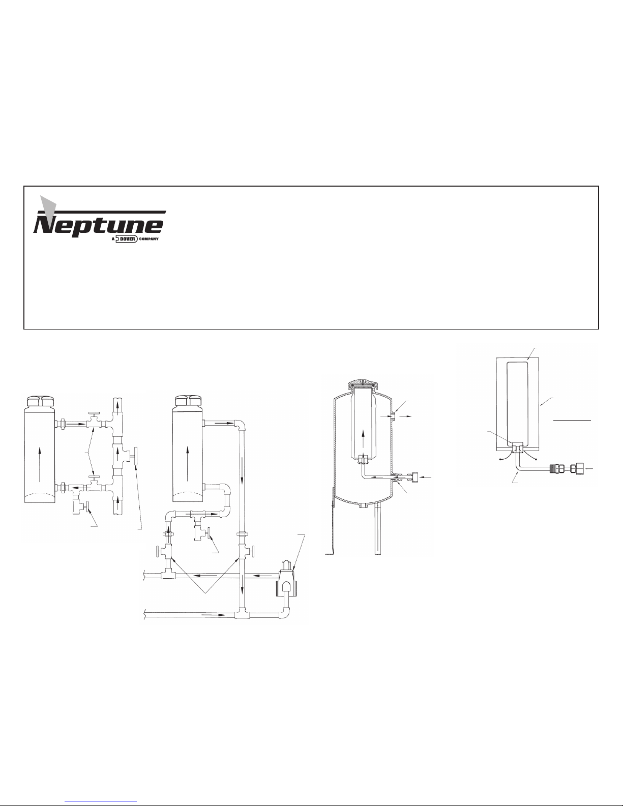
INSTALLATION & OPERATION INSTRUCTIONS – ALL MODELS
1. Pipe feeder to cause pressure drop across inlet and outlet resulting in flow through feeder.
2. Provide isolation and drain valves for servicing and draining.
3. Use with hot or cold water only. DO NOT USE FOR STEAM (300 psi @ 200°F max.).
4. Be certain gasket is positioned in groove under cap before replacing cap. (Replace gasket if cap does
not seal by hand pressure.) Cap should seal with hand tightening pressure only. Do not strike cap with
any tool to seal or unseal.
5. Open valves slowly when returning service.
6. CAUTION! DO NOT OPEN UNDER PRESSURE – close isolation valves and bleed off pressure
before opening.
7. CAUTION! CONTENTS MAY BE HOT.
8. CONSULT YOUR CHEMICAL SUPPLIER FOR THE PROPER USE OF THIS TANK WITH THE CHEMICAL.
9. DO NOT COMBINE CHEMICALS IN THIS DISPENSING DEVICE – without specific instructions from your
chemical supplier. READ AND FOLLOW LABEL DIRECTIONS FOR THE CHEMICAL IN USE.
See instructions for
optional filter bag kit
at right.
INSTALLATION INSTRUCTIONS
FOR FILTER BAG KITS
1. Loosen fitting 1 until the tubing turns in the fitting.
2. Install fitting 1 into the lower side connection of the tank with
the end of the tube pointing upward.
3. Retighten fitting 1 to the tubing. Tube should point straight up.
The ferrule on the tubing is preset for the tank diameter.
4. Place bag over the hanger wire. Pull the drawstring closed and tie tightly so the bag gathers
around the hanger base with the opening of the hanger base protruding from the bag.
5. Insert the bag and hanger base into the tank with the opening of the hanger base pointing
downward. The hanger base should engage the tube which is pointing upward and the
tubing should fit into the hanger base until the tubing rests against the edges of the wire
which protrude into the center of the hanger base.
6. The cap will keep downward force on the wire, keeping the assembly in place.
Important Note:
These instructions describe Neptune Models VTF and DBF By-Pass Feeders with
or without a filter bag plus Model DBFC By-Pass Feeders with Cartridge Filter and
Models FTF and FTF-DB Filter Feeders which use a bag inside the basket filter.
Note carefully the flow arrow shown for each type of feeder. The flow in the
standard by-pass feeder must be “upward” if a filter bag kit is to be used. The flow
on the by-pass feeder with a cartridge filter is “downward.” The filter feeder with
bag and basket filter requires “downward” flow.
Standard By-Pass Feeder
MODELS VTF & DBF
Refer to installation and operation instructions above.
Filter Bag Kit Option
(FOR MODELS VTF & DBF ONLY)
GATE
VALVE
OR
ORIFICE
SHUT
OFF
VALVES
DRAIN
VALVE
DRAIN
VALVE
OUTLET
INLET
90° ELBOW
HANGER BASE
FILTER BAG
FITG1 FITG2
FILTER BAG KITS
INCLUDES:
BAG, BAG FRAME,
TUBING AND
CONNECTORS.
HANGER
SHUT OFF
VALVES
BOILER
FEED
PUMP
Page 2
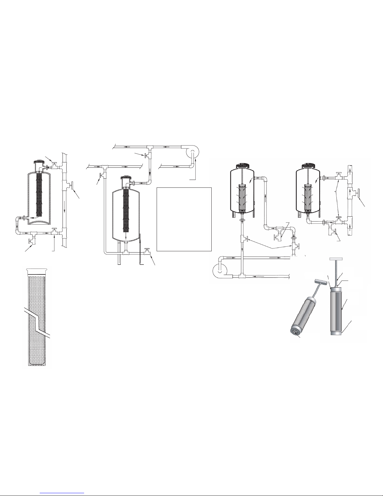
FILTER FEEDER
ASSEMBLY INSTRUCTIONS
Neptune Filter Feeders may be used as a By-Pass Feeder with
or without the basket. The basket may be used for handling
granular chemical products. A filter bag may be placed in the
basket allowing the feeder to also be used as a filter.
The filter bag is placed inside the basket. Bags are available in
1, 5, 20 and 50 micron ratings. The bag slides into the basket
and the ring rests on the top rim of the basket.
The basket is then placed into the feeder and will hang from
the support lip.
Reverse the procedure and insert a clean bag as needed.
CARTRIDGE REMOVAL/REPLACEMENT
INSTRUCTIONS
The cartridge filter assembly consists of two parts:
1. Handle Assembly 2. Filter Cartridge
Remove the cartridge filter assembly from the
vessel by holding the handle (1) and pulling
out straight. Loosen the jam nut just enough
so that the threaded rod can be turned. (This will
ensure the correct length of the handle-cartridge
assembly to fit inside the vessel.) Unscrew threaded
rod to separate bottom cap. Remove old cartridge (2) and discard. Slide a new cartridge (2)
onto the top cap. Slide in the bottom cap. Screw in the threaded rod into the bottom cap until
jam nut touches the top cap. Make sure that the ridge on the face of top and bottom caps line
up with the grooves on the ends of the filter cartridge. Snug the jam nut to secure cartridge.
Check the sealing ring inside the end of the bottom cap and replace if necessary. Slide the
cartridge filter assembly back into the vessel, taking care that the bottom cap is piloted onto
the stub in the bottom of the tank. Make certain assembly is fully seated. Replace the cap.
© 2008 Neptune Chemical Pump Company All Rights Reserved P/N ZL105669 Printed in U.S.A.
Filter Feeder
MODELS FTF & FTF-DB
Refer to installation and operation instructions on other side.
By-Pass Feeder
with Cartridge Filter
MODEL DBFC
Refer to installation and operation instructions
on other side. Maximum flow 6 GPM.
SHUT OFF VALVE
DRAIN VALVE
DRAIN VALVE
GATE VALVE
OR
ORIFICE
SHUT OFF VALVE
BOILER FEED PUMP
SHUT OFF VALVE
SHUT OFF
VALVE
CAUTION!
DO NOT OPEN
UNDER PRESSURE
– close isolation
valves and bleed
off pressure before
opening.
CONTENTS MAY
BE HOT.
JAM NUT
TOP CAP
BOTTOM
CAP
SEALING
RING
DRAIN
VALVE
DRAIN
VALVE
SHUT OFF
VALVES
S
HUT
O
FF
V
ALVES
GATE
VALVE
OR
ORIFICE
CARTRIDGE FILTER
ASSEMBLY
 Loading...