

Neptune E-CODER R900i Maintenance Manual

E-CODER®)R900i™
Installation and Maintenance Guide


E-CODER®)R900i™
Installation and Maintenance Guide

Copyright
This manual is an unpublished work and contains the trade secrets and
confidential information of Neptune Technology Group Inc., which are not to be
divulged to third parties and may not be reproduced or transmitted in whole or
part, in any form or by any means, electronic or mechanical for any purpose,
without the express written permission of Neptune Technology Group Inc. All
rights to design or inventions disclosed herein, including the right to
manufacture, are reserved to Neptune Technology Group Inc.
Neptune engages in ongoing research and development to improve and
t
enhance its products. Therefore, Neptune reserves the right
o change product
or system specifications without notice.
Trademarks Used in this Manual
ProRead and E-CODER are a trademarks of Neptune Technology Group Inc.
R900 is a registered trademark of Neptune Technology Group Inc.
E-CODER)R900i is a trademark of Neptune Technology Group Inc. Other brands
or product names are the trademarks or registered trademarks of their
respective holders.
FCCNotice
This device complies with Part 15 of the FCC Rules. Operation is subject to the
following two conditions:
l This device may not cause harmful interference.
l This device must accept any interference received, including interference that
may cause undesired operation.
Note: This equipment has been tested and found to comply with the limits for a
Class B digital device, pursuant to Part 15 of the FCCRules. These limits are
designed to provide reasonable protection against harmful interference in a
residential installation. This equipment generates, uses, and can radiate radio
frequency energy, and if not installed and used in accordance with the
instructions, may cause harmful interference to radio communications.
However, there is no guarantee that interference will not occur in a particular
installation. If this equipment does cause harmful interference to radio or
television reception, which can be determined by turning the equipment off and
on, the user is encouraged to try to correct the interference by one or more of
the following measures:
l Reorient or relocate the receiving antenna.
l Increase the separation between the equipment and receiver.

RF Exposure Information
This equipment complies with the FCC RF radiation requirements for
uncontrolled environments. To maintain compliance with these requirements,
the antenna and any radiating elements should be installed to ensure that a
minimum separation distance of 20 cm is maintained from the general
population.
Changes or modifications not expressly approved by the party responsible for
compliance could void the users' authority to operate the equipment.
Professional Installation
In accordance with section 15.203 of the FCCrules and regulations, the Meter
Interface Unit (MIU) must be professionally installed by trained meter installers.
Changes or modifications not expressly approved by the party responsible for
compliance void the user's authority to operate the equipment.
Industry Canada
This Class B digital apparatus meets all requirements of theCanadian
Interference Causing Equipment Regulations. Operation is subject to the
following two conditions:
l This device may not cause harmful interference.
l This device must accept any interference received, including interference that
may cause undesired operation.
Cet appareillage numérique de la classe B répond à toutes les exigences de
l'interférence canadienne causant des règlements d'équipement. L'opération
est sujette aux deux conditions suivantes: (1) ce dispositif peut ne pas causer
l'interférence nocive, et (2) ce dispositif doit accepter n'importe quelle
interférence reçue, y compris l'interférence qui peut causer l'opération peu
désirée.

E-CODER®)R900i™
Installation and Maintenance Guide
Literature No. IME-CODER)R900i 12.18
Part No. 12560-002
Copyright © 2006 - 2018
Neptune Technology Group Inc.
All Rights Reserved.
Neptune Technology Group Inc.
1600 Alabama Highway 229
Tallassee, AL 36078
Tel: (800) 633-8754
Fax: (334) 283-7293

Contents
Chapter 1: Product Description
E-CODER®)R900i™ Programming
Chapter 2: Specifications
Electrical Specifications
E-CODER)®R900i™ Dimensions
Chapter 3: Installing the E-CODER®)R900i™
Prior to Installation
Storage 5
Unpacking 5
Safety and Preliminary Checks 5
Site Selection
Installing the E-CODER®)R900i™
New Meter Installation 6
Retrofit Meter Installation 7
1
2
3
3
4
5
5
6
6
Connecting the E-CODER®)R900i™ Through-the-Lid Antenna
Installing the Antenna
Attaching the Antenna to the MIU
Chapter 4: Activating and Reading the E-CODER®)R900i™
Activating the LCD Using the Solar Panel 11
Read the Meter 12
Common Causes of Leaks 13
How to Tell if Water is in Use 14
What to Do if There is a Leak 14
If a Continuous Leak is Repaired 14
If an Intermittent Leak is Repaired 14
7
8
9
11
E-CODER®)R900i™ Installation and Maintenance Guide v

Contents
Chapter 5: Data Logging Extraction 15
About Data Logging 15
Accessing Data Logging 15
Initiating RF Activated Data Logging 20
Sample Data Logging Graphs 22
Off Cycle Data Extraction 23
Belt Clip Transceiver 24
Chapter 6: Maintenance and Troubleshooting 25
Six- and Four-Wheel Encoders 25
Six-Wheel Encoder Normal Operation 25
Four-Wheel Encoder Normal Operation 25
Troubleshooting 26
Contact Information 26
By Phone 26
By Fax 27
By Email 27
Appendix 12: E-CODER®)R900i™ Flags
Description of Flags 29
Glossary 31
Index 33
29
vi E-CODER®)R900i™ Installation and Maintenance Guide

Figures
Figure 1 – E-CODER®)R900i™
Figure 2 – Inside Dimensions
Figure 3 – Antenna Dimensions
Figure 4 – E-CODER®)R900i™ Antenna
Figure 5 – Insert the Antenna into the Pit Lid
Figure 6 – Locking Nut on Antenna
Figure 7 – Secure the Locking Nut
Figure 8 – Installation Complete
Figure 9 – Remove the Protective Cap and Gasket
Figure 10 – Align the F Connector
Figure 11 – Seat the Connection
Figure 12 – Solar Panel for the E-CODER®)R900i™
Figure 13 – Activating the E-CODER®)R900i™
1
4
4
7
8
8
8
9
9
9
10
11
11
Figure 14 – HHU Home Screen
Figure 15 – N_SIGHT® R900 Menu Screen
Figure 16 – Data Logger Option
Figure 17 – Reader ID Input
Figure 18 – HHU Time Confirmation
Figure 19 – Initialize RF Device
Figure 20 – Enter MIU ID
Figure 21 – Capture Button
Figure 22 – Unit of Measure and Meter Size
Figure 23 – Start Button
Figure 24 – E-CODER®)R900i™ Listens for Data
Figure 25 – E-CODER®)R900i™ Receives Data
Figure 26 – Graph Button
15
16
16
17
17
18
18
19
19
20
20
21
21
Figure 27 – Example Data Logging Graphs
E-CODER®)R900i™ Installation and Maintenance Guide vii
22

Figures
Figure 28 – HHU Home Screen 23
Figure 29 – HHU Menu 23
Figure 30 – Off Cycle Option 24
viii E-CODER®)R900i™ Installation and Maintenance Guide

Tables
Table 1 – E-CODER®)R900i™ Specifications
Table 2 – Icons and Displays
Table 3 – Causes of Leaks
Table 4 – Data Logging Graph Legend
Table 5 – Example Reading Values
Table 6 – Eighth Digit Resolution by Meter Size
Table 7 – E-CODER®)R900i™ Flags
3
12
13
22
26
29
29
E-CODER®)R900i™ Installation and Maintenance Guide ix

Tables
This page intentionally left blank.
x E-CODER®)R900i™ Installation and Maintenance Guide
Chapter 1: Product Description
This chapter provides a general description of the Neptune®E-CODER®)R900i™ register.
The E-CODER)R900i is an integrated register containing both the E-CODER®and R900
technologies in one register that collects meter data. It then transmits the data that a meter
reader collects. A Neptune walk-by, mobile, R900 Gateway®fixed network data collection
system, or LoRa®fixed network collection system receives the data and stores it to
download into the utility billing system for processing.
The E-CODER)R900i is easily installed and operates within a radio frequency (RF) band which
does not require an operating license. The E-CODER)R900i meets FCC regulations part
15.247 allowing higher output power and greater range. It uses frequency-hopping spread
spectrum technology to avoid RF interference and enhance security. The transmitted data is
updated at 15-minute intervals and transmits a mobile message that includes the meter
reading data and the unique E-CODER)R900i ID every 14-20 seconds. This allows the meter
to be read by a hand-held unit (HHU) or mobile data collections unit.
The E-CODER)R900i also transmits a high-power fixed network message every seven and
one-half minutes on an interleaved basis to an R900 Gateway. If connected to a LoRa
network, the E-CODER)R900i can transmit a high-power fixed network message every three
hours on an interleaved basis.
®
The E-CODER)R900i is designed to offer advantages to utility organizations of all sizes:
l Increases meter reading accuracy
l Eliminates hard-to-read meters
l Protects utility liability by increasing meter reader safety
l Requires no external wiring or programming
l Provides enhanced eight-digit AMR meter reading
l Provides proactive customer service benefits (leak, tamper, and backflow detection)
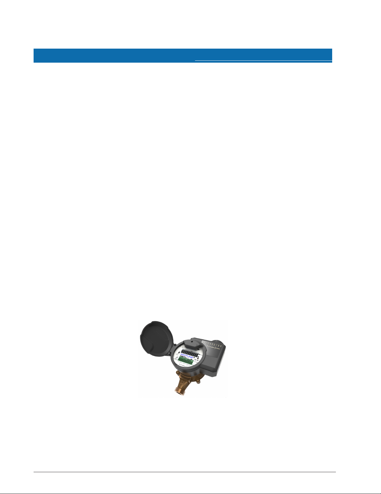
Figure 1 – E-CODER®)R900i™
E-CODER®)R900i™ Installation and Maintenance Guide 1

Chapter 1: Product Description
E-CODER®)R900i™ Programming
The E-CODER)R900i is NOT field-programmable. At the factory, each of the following items is
programmed into the Meter Interface Unit (MIU):
l Serial number - each MIU is given a unique serial number / identification number
l Meter size and change gear information
2
E-CODER®)R900i™ Installation and Maintenance Guide

This chapter defines the specifications for the E-CODER®)R900i™.
Specification Description
Power Lithium battery
Transmitter Specifications
Transmit Period
l Every 14 to 20 seconds – standard R900 mobile message
l Every seven and one-half minutes – standard R900 fixed
network message
l Every three hours – standard LoRa
®
fixed network message
Transmitter Channels
l 50 for R900 mobile and fixed
l 64 for LoRa fixed network message
Channel Frequency 902-928 MHz
Output Power Meets FCC Part 15.247
FCC Verification Part 15.247
Environmental Conditions
Operating Temperature –22º to 149ºF (-30º to 65ºC)
Storage Temperature –40º to 158ºF (-40º to 70ºC)
Operating Humidity 0 to 100% Condensing (pit only)
Functional Specifications
Register Reading
l Eight digits (AMR)
l Nine digits (Visual)
MIU ID
l Nine digits (R900 v5)
l 10 digits (R900 v4)
Dimensions and Weight
Dimensions Refer to the figures on the following page.
Weight
l Inside – 1.39 lbs. (630.5 grams)
l Pit – 1.62 lbs. (734.8) grams)
Electrical Specifications
The following table defines the specifications for the E-CODER R900i.
Chapter 2: Specifications
Table 1 – E-CODER®)R900i™ Specifications
E-CODER®)R900i™ Installation and Maintenance Guide 3
 Loading...