

Page 1
E-CODER® Quick Install Guide
QUICK INSTALL GUIDE
®
E-CODER
Page 2

Page 3
1 General Instructions
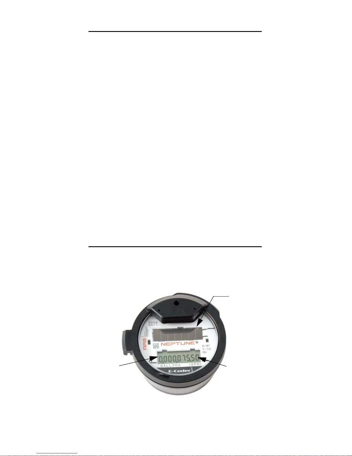
Solar panel
Nine-digit
meter reading
LCD
display
The E-CODER® is an electronic absolute encoder register
designed for use with Neptune’s Automatic Reading and Billing
®
(ARB
) System. This register operates with Neptune’s R900
and R450™ MIUs, providing advanced features such as leak,
backflow, and tamper detection.
With the E-CODER register, both the homeowner and the utility
can use the following features.
• Nine-digit display for visual reading
• Eight digits for billing
• Water flow indicators
• Intermittent leak detection icon on LCD panel
• Continuous leak detection icon on LCD panel
This guide can help you identify and read information displayed
on the E-CODER register. It can also help you recognize the
common causes of leaks and what to do if a leak is found. After
the leak is repaired, this guide also contains steps to determine
that the leak is no longer evident.
®
2 Product Description
The face of the E-CODER allows you to read various types of
information available. The face of the E-CODER is shown in
Figure 1.
Figure 1 E-CODER Coder Face
1
Page 4
3 Wiring Inside Set Version
Run a three-conductor cable from the E-CODER register to the
MIU. Refer to the following steps.
1 Connect the three-conductor wire to the encoder register’s
terminals as described in the manufacturer’s instructions,
using the color code in Table 1.
Table 1 Encoder Wiring
Register Wire Color / Encoder Terminal
Neptune E-CODER Black/B Green/G Red/R
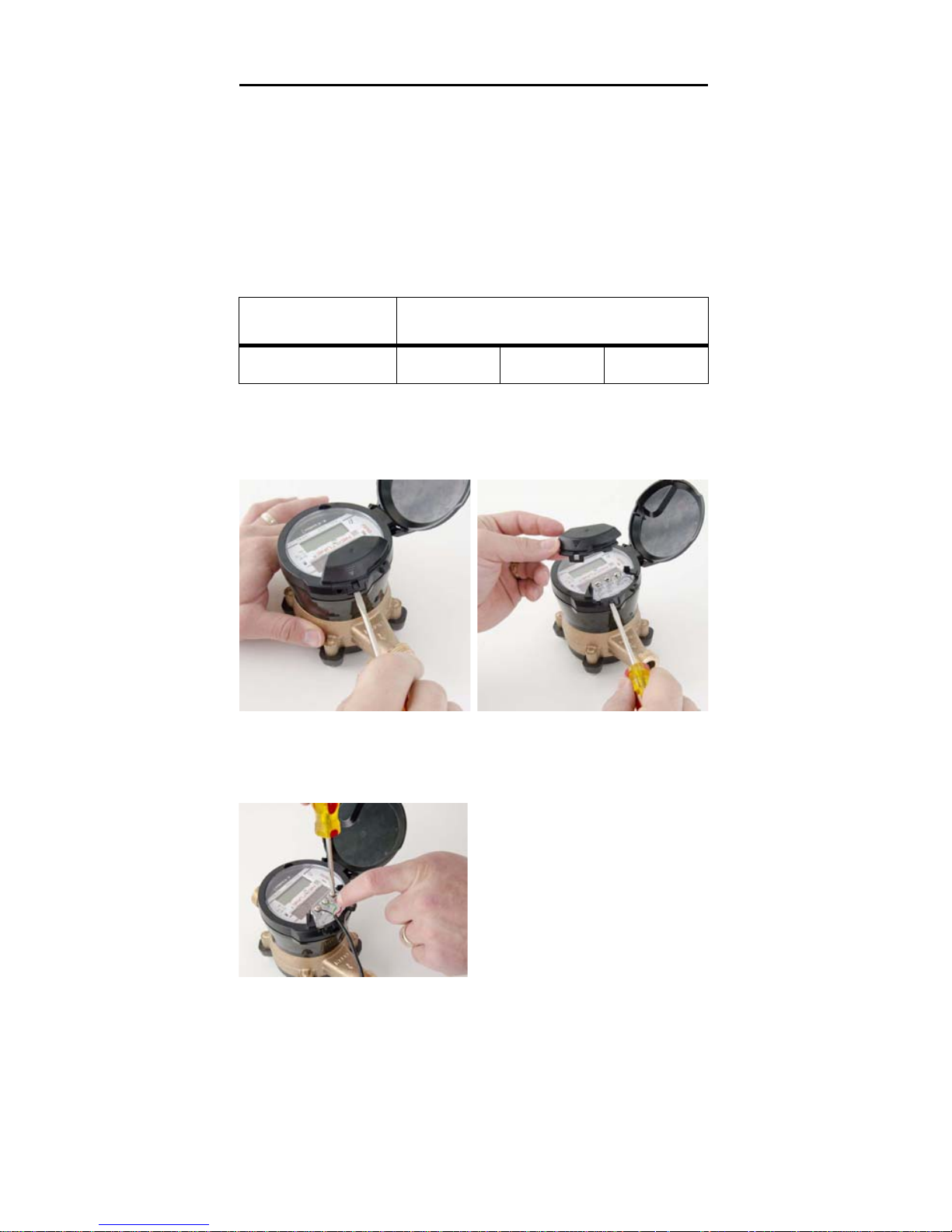
2 Remove the terminal cover with a flat-head screw driver as
shown in Figure 2.
Figure 2 Removing the Terminal Cover
3 Wire the encoder register
with the proper colors. See
Figure 3.
4 Test the wiring to verify the
read.
Figure 3 Wiring with Proper Color Wire
2
Page 5
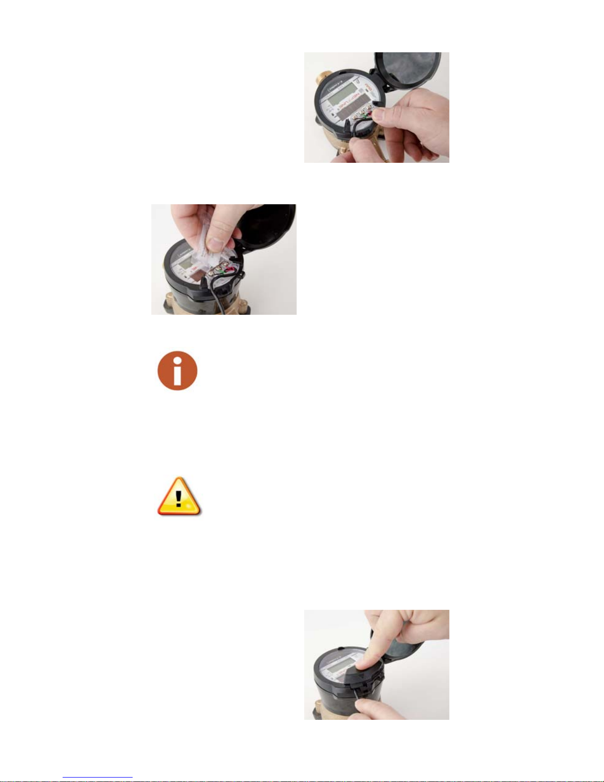
5 Route the wire as shown in
Figure 4.
Figure 5 Applying Compound
Figure 4 Routing the Wire
6 Apply Novagard G661 or
Dow Corning
®
Compound
#4 to the terminal screws
and exposed bare wires.
See Figure 5.
Neptune recommends Novaguard G661 or Dow
Corning Compound #4.
Novagard may cause irritation to eyes and skin.
If swallowed, do not induce vomiting; dilute
with one to two glasses of water or milk and
seek medical attention. Please refer to:
• MSDS Novagard Silicone Compounds &
Grease Inc. 5109 Hamilton Ave. Cleveland,
OH 44114, 216-881-3890.
• For copies of MSDS sheets, please
call Neptune’s Customer Support
at (800) 647-4832.
7 Place terminal cover on the
register, ensuring wire is
routed through strain relief.
See Figure 6.
Figure 6 Placing Cover on Register
3
Page 6
8 Snap the terminal cover in
place by pressing on the
molded arrow as shown in
Figure 7.
Figure 7 Snapping Cover in Place
9 Proceed to “How to Activate” on page 10.
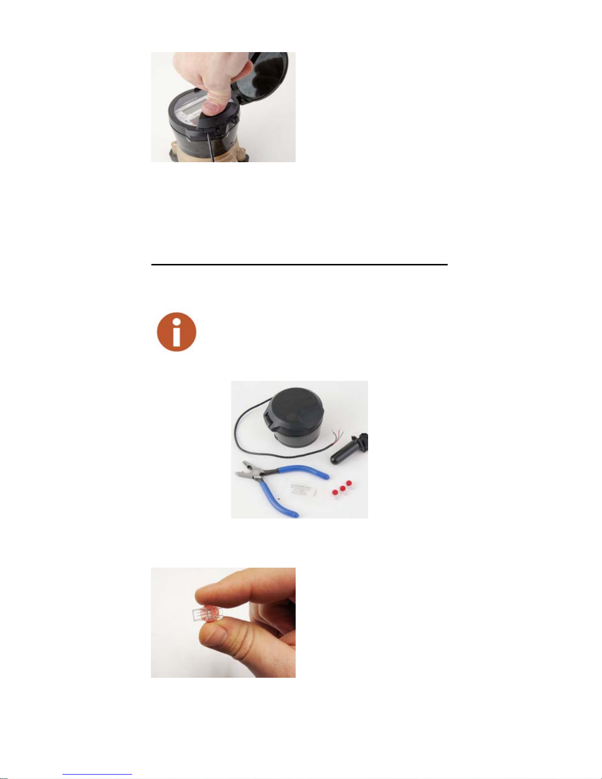
4 Wiring the Pit Set Version
Complete the steps to wire the pit set version.
Figure 8 shows the components required for
installation.
Figure 9 Scotchlok Connector
Figure 8 Installation Components
1 Hold the Scotchlok
between the index finger
and thumb with the red cap
facing down. See Figure 9.
4
Page 7

2 Take one non-stripped black
Red and green wires not fully seated
wire from the pigtail and one
from the receptacle/MIU by
inserting the wires into the
Scotchlok connector until
fully seated. See Figure 10.
Figure 10 Seating Connector Wires
Do not strip the colored insulation from the
wires or strip and twist the bare wires prior to
inserting in the connector. Insert the insulated
colored wires directly into the Scotchlok
connector.
3 Place the connector red
cap side down between the
jaws of the UR crimping
tool as shown in Figure 11.
Refer to Table 3 on
page 10 for part numbers.
Figure 11 UR Crimping Tool
4 Check to ensure that the
wires are still fully seated
in the connector before
crimping the connector.
Figure 12 illustrates
improper connections
due to wires not being
fully seated.
Figure 12 Improper Connections
5 Squeeze the connector firmly with the proper crimping tool
until you hear a pop and gel oozes out the end of the
connector.
5
Page 8

6 Repeat steps one through five for each color wire. See
Table 2 for the wiring configuration to connect Neptune MIUs
or competitive MIUs to the E-CODER.
Table 2 Color Codes for Wires
MIU Wire Color / Encoder Terminal MIU Type
Black/B Green/G Red/R R900
Black/B Green/G Red/R R450
Black/G Green/R Red/B Sensus
Black/B White/G Red/R Itron
Black/G White/R Red/B Aclara
Black/G Green/B Red/R Elster
Black/G Green/R Red/B Badger
7 After all three color wires
have been connected, read
the encoder register to
ensure proper connections,
and the receptacle/MIU is
functioning properly. See
Figure 13.
Figure 13 Three Color Wires Connected
Figure 14 Splice Tube
8 Take all three connected
Scotchloks and push into
the splice tube until fully
covered by the silicone
grease. See Figure 14.
6
Page 9

9 Separate the gray wires,
and place in the slots on
each side of the splice tube
as shown in Figure 15.
Figure 16 Cover in Place
Figure 15 Gray Wires in Slot
10 Snap the cover closed to
finish the installation as
shown in Figure 16.
11 Proceed to “How to Activate” on page 10.
5 Installation Instructions for Networked
Receptacle/Dual Port MIUs
Enhanced R900 v4 MIUs are not Dual Port
capable. These instructions only apply to v3
MIUs.
The Dual Port R900 and R450 MIUs work only with Neptune
ProRead™ or E-CODER registers. Each register must be
programmed in “RF Network” mode prior to installation.
• E-CODER registers cannot be programmed
while connected together in a network. Each
register must be programmed separately
prior to making the network connection.
• The designations HI and LO are
Neptune's designations for the high (HI) flow
or turbine side of the compound, and the low
(LO) flow or disc side of the compound.
• The settings can also be used to designate
the primary (HI) and secondary (LO) meters
in a dual set application
7
Page 10

Programming the HI Register
To complete the following steps, use the Neptune field
programmer to select the ProRead Program tab for
programming.
1 Select RF Compound HI
format.
2 Match the Connectivity
2W.
3 Match the Dial Code 65.
4 Type the appropriate
register ID.
5 Program the register.
6 Read or query the register to
confirm correct
programming. See
Figure 17.
Figure 17 HI Register
Programming the LO Register
To complete the following steps, use the Neptune field
programmer to select the ProRead Program tab for
programming.
1 Select RF Compound LO
format.
2 Match the Connectivity 2W.
3 Match the Dial Code 65.
4 Type the appropriate register
ID.
5 Program the register.
6 Read or query the register to
confirm correct
programming. See
Figure 18.
Figure 18 LO Register
8
Page 11

6 Wiring Networked Registers
Complete the steps to wire networked registers.
1 Connect each color wire with the appropriate color wire from
the pigtail and both registers, until all three colors have been
successfully connected. See Figure 19.
Figure 19 Interconnection of Like Terminals
• Remove any bare or non-insulated wire. Make
sure that you only insert insulated wire into the
splice connector.
• Observe proper polarity when wiring the
registers, so that all terminals are
interconnected with wires of the same color:
red, black, or green. Refer to Figure 19.
2 Proceed to “How to Activate” on page 10.
7 Crimping Tool Manufacturers
To apply the Scotchlok connectors, Neptune requires the use of
a proper crimping tool. Table3 on page10 shows a list of various
manufacturers and model numbers.
9
Page 12

Table 3 Proper Crimping Tools
Manufacturer Manufacturer’s Model Number
E-9R (10:1)*
E-9BM (10:1)
3M
Eclipse Tools 100-008
* To reduce fatigue, use a tool within each splicing group with the highest
mechanical advantage indicated within the parentheses ().
E-9C/CW (7:1)
E-9E (4:1)
E-9Y (3:1)
Use of normal pliers or channel locks is highly
discouraged because they do not apply even
pressure and can result in an improper connection.
8 How to Activate
To read the E-CODER you must first activate it.
Complete the following steps to activate the E-CODER.
1 Expose the E-CODER to sunlight or activate with a flashlight
for five seconds.
If the LCD is able to power on, but there is
insufficient light to read the ASIC, the LCD displays
LO LIGHT. See Figure 20.
Figure 20 LCD Displaying LO Light
2 Verify that the following LCD displays appear.
• The All-Segment test appears for two seconds.
• The version number appears for two seconds.
• The event index value appears for 20 seconds.
• The flow rate appears for four seconds.
• The display alternates between the reading and the flow
rate every 12 seconds.
10
Page 13

9 How to Read
It is important to become familiar with the information available
from the meter. Figure21 lists various icons and displays along
with a description of each.
Figure 21 Icons and Displays
11
Page 14

10 Common Causes of Leaks
If the leak indicator is Flashing or Continuously ON, the
E-CODER is indicating that a possible leak may exist. Leaks can
result from various circumstances. To better help you identify a
possible leak, the following table contains some common causes
of leak problems that can occur.
Ta ble 4 Possible Leaks
Possible Cause of Leak
Outside faucet, garden or
sprinkler system leaking
Toilet valve not sealed
properly
Toilet running
Faucet in kitchen or
bathrooms leaking
Ice maker leaking
Soaker hose in use
Leak between the water
meter and the house
Intermittent
Leak
Continuous
Leak
Washing machine leaking
Dishwasher leaking
Hot water heater leaking
Watering yard for more than
eight hours
Continuous pet feeder
12
Page 15

Ta ble 4 Possible Leaks
Possible Cause of Leak
Water-cooled air conditioner
or heat pump
Filling a swimming pool
Any continuous use of water
for 24 hours
Intermittent
Leak
Continuous
Leak
11 How to Tell if Water is in Use
To determine if water is in use, complete the following steps.
1 Check the flow indicator by watching for two
minutes.
2 Determine which of the following conditions exists.
• If the arrow is Flashing, then water is running very
slowly.
• If the arrow is Continuously ON, water is running.
• If the arrow is not Flashing, water is not running.
12 What to Do if There is a Leak
The following checklist can be helpful if the E-CODER leak
indicator shows a possible leak.
Table 5 Checklist for Leaks
Check all faucets for possible leaks.
Check all toilets and toilet valves.
Check the ice maker and water dispenser.
Check the yard and surrounding grounds for a wet
spot or indication of a pipe leaking.
13
Page 16

13 If Continuous Leak is Repaired
If a continuous leak is found and repaired, complete the following
steps.
1 Use no water for at least 15 minutes.
2 Check the leak icon.
If the leak indicator changes from Continuously ON to
Flashing, then a continuous leak is no longer indicated.
14 If Intermittent Leak is Repaired
If an intermittent leak is found and repaired, complete the
following steps.
1 Check the leak icon after at least 24 hours.
If the leak has been correctly repaired, the leak icon
changes from Flashing to OFF.
2 Refer to the following tables which describe the standard
functions of the E-CODER flags.
Ta ble 6 E-CODER Flags
Backflow Flag (Resets After 35 Days)
Based on reverse movement of the eighth digit, the eighth
digit is variable based on the meter size.
No backflow event Eighth digit reversed less than one digit
Minor backflow
event
Major backflow
event
Leak Status Flag (Resets After 35 Days)
Based on total amount of 15-minute periods recorded in the
previous 24-hour period.
Eighth digit reversed more than one
digit up to 100 times the eighth digit
Eighth digit reversed greater than 100
times the eighth digit
Leak icon off Eighth digit incremented less than 50 of
the 96 15-minute intervals
14
Page 17

Backflow Flag (Resets After 35 Days)
Flashing leak icon Eighth digit incremented in 50 of the 96
15-minute intervals
Solid leak icon Eighth digit incremented in all of the 96
15-minute intervals
Consecutive Days with Zero Consumption Flag (Resets
After 35 Days)
Number of days the “leak status” was at a minimum value
15 Contact Information
Within the United States, Neptune Customer Support is available
Monday through Friday, 7:00 AM to 5:00 PM Central Standard
Time, by telephone, email, or fax.
By Phone
To contact Neptune Customer Support by phone, complete the
following steps.
1Call (800) 647-4832.
2 Select one of the following options.
• Press 1 if you have a Technical Support Personal
Identification Number (PIN).
• Press 2 if you do not have a Technical Support PIN number.
3 Enter the six-digit PIN number and press #.
4 Select one of the following options.
•Press 2 for Technical Support.
• Press 3 for maintenance contracts or renewals.
• Press 4 for Return Material Authorization (RMA) for
Canadian Accounts.
You are directed to the appropriate team of Customer
Support Specialists. The specialists are dedicated to you
until the issue is resolved to your satisfaction. When you
call, be prepared to give the following information.
• Your name and utility or company name.
• A description of what occurred and what you were doing at
the time.
• A description of any actions taken to correct the issue.
15
Page 18

By Fax
To contact Neptune Customer Support by fax, send a description
of your problem to (334) 283-7497. Please include on the fax
cover sheet the best time of day for a customer support specialist
to contact you.
By Email
To contact Neptune Customer Support by email, send your
message to hhsupp@neptunetg.com.
Notes
16
Page 19

Page 20

neptunetg.com
Neptune Technology Group Inc.
1600 Alabama Highway 229
Tallassee, AL 36078
USA
Tel: (800) 645-1892
Fax: (334)283-7293
Neptune Technology Group (Canada) Ltd.
7275 West Credit Avenue
Mississauga, Ontario
L5N 5M9
Canada
Tel: (905) 858-4211
Fax: (905) 858-0428
Neptune Technology Group Inc.
Avenida Ejército Nacional No. 418
Piso 12, Desp. 1203
Colonia Polanco V Sección
Delegación Miguel Hidalgo
11560 México, Distrito Federal
Tel: (525) 55203 5294 / (525) 55203 4032
Fax: (525) 55203 6503
QI E-CODER 02.17 Part No. 12563-001
© Copyright 2003- 2017, Neptune Technology Group Inc.
Neptune is a registered trademark of Neptune Technology Group Inc.
Take Control
 Loading...