

Neptune Bath, Whirlpool, Mass-air, Activ-air Owner's Manual
Bath Whirlpool Mass-air Activ-air
Installation Operation Maintenance Repair
NEPTUNE OWNER’S MANUAL
Do not discard. Save these instructions for further use

TABLE OF CONTENTS
NTRODUCTION
I
Important safety instructions . . . . . . . . . . . . . . . . . . . . . . . . . . . . . . . . . . . Page 3
Summary of precautions
NSTALLATION
I
Before you begin . . . . . . . . . . . . . . . . . . . . . . . . . . . . . . . . . . . . . . . . . . . . . Page 3
ools required . . . . . . . . . . . . . . . . . . . . . . . . . . . . . . . . . . . . . . . . . . . . . . . Page 3
T
TABLE OF CONTENTS
Materials required . . . . . . . . . . . . . . . . . . . . . . . . . . . . . . . . . . . . . . . . . . . . Page 3
Site preparation . . . . . . . . . . . . . . . . . . . . . . . . . . . . . . . . . . . . . . . . . . . . . . P age 4
Recessed Installation . . . . . . . . . . . . . . . . . . . . . . . . . . . . . . . . . . . . . . . . . . Page 4
Tiling Flange (recessed installation of a podium style bath) . . . . . . . . . . . Page 5
Podium Installation . . . . . . . . . . . . . . . . . . . . . . . . . . . . . . . . . . . . . . . . . . . Page 6
Plumbing Installation . . . . . . . . . . . . . . . . . . . . . . . . . . . . . . . . . . . . . . . . . . Page 7
System hook-up (electrical installation) . . . . . . . . . . . . . . . . . . . . . . . . . . . Page 7
Finishing walls, decks and podiums . . . . . . . . . . . . . . . . . . . . . . . . . . . . . . Page 9
Optional Bath Skirt installation . . . . . . . . . . . . . . . . . . . . . . . . . . . . . . . . . . Page 9
Fixed height skirts . . . . . . . . . . . . . . . . . . . . . . . . . . . . . . . . . . . . . . . . . . . Page 10
Ajustable height skirts . . . . . . . . . . . . . . . . . . . . . . . . . . . . . . . . . . . . . . . . Page 10
OPERATING INSTRUCTIONS
On/Off control . . . . . . . . . . . . . . . . . . . . . . . . . . . . . . . . . . . . . . . . . . . . . . Page 11
Variable speed control . . . . . . . . . . . . . . . . . . . . . . . . . . . . . . . . . . . . . . . Page 11
Whirlpool multi-cycle control (optional) . . . . . . . . . . . . . . . . . . . . . . . . . Page 11
Mass-air & Activ-air control . . . . . . . . . . . . . . . . . . . . . . . . . . . . . . . . . . . . Page 11
Combo control . . . . . . . . . . . . . . . . . . . . . . . . . . . . . . . . . . . . . . . . . . . . . Page 12
Whirlpool: Ajustable jets . . . . . . . . . . . . . . . . . . . . . . . . . . . . . . . . . . . . . . Page 12
Whirlpool: Air induction . . . . . . . . . . . . . . . . . . . . . . . . . . . . . . . . . . . . . . . Page 12
Back-jets: Diverter valve (option) . . . . . . . . . . . . . . . . . . . . . . . . . . . . . . . Page 12
. . . . . . . . . . . . . . . . . . . . . . . . . . . . . . . . . . . . . . . Page 3
NEPTUNE OWNER’S MANUAL
Welcome to the Neptune universe.
Your new Neptune bath is a top of the
MAINTENANCE
Routine cleaning . . . . . . . . . . . . . . . . . . . . . . . . . . . . . . . . . . . . . . . . . . . . Page 13
Mass-air and Activ-air systems . . . . . . . . . . . . . . . . . . . . . . . . . . . . . . . . . Page 13
Whirlpool maintenance . . . . . . . . . . . . . . . . . . . . . . . . . . . . . . . . . . . . . . . Page 13
Stains . . . . . . . . . . . . . . . . . . . . . . . . . . . . . . . . . . . . . . . . . . . . . . . . . . . . . Page 13
age 13
Light bulb replacement
REPAIRS
Minor scratch repair . . . . . . . . . . . . . . . . . . . . . . . . . . . . . . . . . . . . . . . . . Page 13
Major damage repair . . . . . . . . . . . . . . . . . . . . . . . . . . . . . . . . . . . . . . . . . Page 13
TROUBLESHOOTING . . . . . . . . . . . . . . . . . . . . . . . . . . . . . . . . . . . . . . . . . Page 14
HYDRO-MASSAGE
Introduction . . . . . . . . . . . . . . . . . . . . . . . . . . . . . . . . . . . . . . . . . . . . . . . . Page 15
Modern Hydro-massage
Massage . . . . . . . . . . . . . . . . . . . . . . . . . . . . . . . . . . . . . . . . . . . . . . . . . . . Page 15
Temperature . . . . . . . . . . . . . . . . . . . . . . . . . . . . . . . . . . . . . . . . . . . . . . . . Page 15
Aromatherapy
Nutrient transfer
Chromatherapy . . . . . . . . . . . . . . . . . . . . . . . . . . . . . . . . . . . . . . . . . . . . . Page 16
Conclusion . . . . . . . . . . . . . . . . . . . . . . . . . . . . . . . . . . . . . . . . . . . . . . . . . Page 16
IMPORTANT INFORMATION TO SAFEGAURD . . . . . . . . . . . . . . . . . . Page 16
. . . . . . . . . . . . . . . . . . . . . . . . . . . . . . . . . . . . . . . . . . . . . .
. . . . . . . . . . . . . . . . . . . . . . . . . . . . . . . . . . . . . . .
. . . . . . . . . . . . . . . . . . . . . . . . . . . . . . . . . . . . . .
. . . . . . . . . . . . . . . . . . . . . . . . . . . . . . . . . . . . . . . . . . . .
P
Page 15
age 16
P
age 1
P
line product that will give you years of
pleasure and relaxation if it is installed
and maintained correctly.
We encourage you to read and understand all of the safety, installation and
maintenance instructions included in
this owner’s manual. It is strongly
recommended that the installation of
your bath be carried out by competent,
qualified and accredited professionals
in accordance with governmental
building codes and by-laws.
6
NEPTUNE ...
The art in baths!

INSTALLATION
EFORE YOU BEGIN
B
Before you begin the installation of your new Neptune bath it is
strongly suggested that you do the following:
Inspect your bath visually to make sure that it has not been
•
damaged during transportation.
be damage do not install the bath.
• Make sure that the bath is the unit that you ordered and that its
dimensions and drain-side correspond to your plans.
Never use the pump, piping or jets to lift or manipulate your
•
bath, as this can damage both the equipment and the water
connections into the bath.
• The bath should be placed in the bathroom and the floor should
be checked for level. Make sure that the floor is solid enough to
support the weight of the bath when it is full (1000 lbs average).
The feet of the bath must be in contact with the floor.
It cannot be suspended by the perimeter alone.
• For optional non-adjustable skirt installation, the bath must be
installed at the correct height to facilitate installation of the skirt
(see table 1 for height information)
An access panel is mandatory. Most building codes require
•
that there be an access panel a minimum of 30 cm x 55 cm
(12” x 22”) in order to service the plumbing, motor, control unit
and keypad.
• In order to protect the bath during installation a piece of
cardboard should be cut out of the box and placed in the
bottom of the bath.
•
If there is a protective plastic sheet covering the surface of your bath,
it should not be removed until the installation is complete. When
necessary during the installation process the plastic can be peeled
back for installation of the drain, overflow and surface mounted
plumbing fixtures. The plastic should also be peeled back in areas
where it could become snagged during the installation process.
If you suspect that there may
tight
• If your bath is equipped with a W
system you must test it before final installation. T
hirlpool, Mass-air or Activ-air
hese systems
are tested at the factory but can be loosened by transportation
and installation.
• Remember that the Whirlpool, Mass-air and Activ-air systems
must be hooked-up before the final installation.
• If your bath is equipped with adjustable metal feet they should
be installed now by threading them into the metal suppor
t rails
underneath the bath.
TOOLS REQUIRED
• Level
• Hole-saw (for surface mount faucet installation)
• Sabre saw for podium installation
• Safety glasses
• Tape measure
• Caulking gun
MATERIALS REQUIR ED
• Bathroom grade (mildew resistant) silicone caulking
• Construction Adhesive
• Adjustment shims (except for baths equipped with adjustable feet)
• 1” X 2” Wood strip for attachment to the walls
• 2” X 3” Wood stock for building podium or apron
• 5/8” Exterior grade plywood for covering podium or apron
• No. 8 x 11/4” wood screws
• Bath drain and overflow kit (available from your Neptune dealer)
• Mortar (optional mortar bed installation only)
INSTALLATION
IMPORTANT SAFETY INSTRUCTIONS
WARNING: When using this unit and any electrical product basic
precautions should always be followed, including the following:
DANGER: Risk of electric shock. This unit must be connected only to
a circuit that is protected by a class-A ground fault circuit interrupter
(GFCI). Grounding is required, this unit should be installed by a
qualified service representative and grounded. Install to permit access
for servicing.
WARNING: Risk of electric shock. A licensed electrician should make
all electrical connections.
WARNING: Risk of electric shock.
NG:
I
N
AR
W
understand all instructions thoroughly before beg
including the following requirements.
• Follow all local plumbing and electrical codes.
• Provide unrestricted access to the pump. Access must be provided
for servicing the pump and controls. The access must be located
immediately next to the pump.
WARNING: Unauthorized modification may cause unsafe operation
and poor performance of the Whirlpool, Mass-air and Activ-air
systems.
personal injury or damage caused by any such unauthorized modification.
WARNING: Risk of child drowning. T
drowning, do not permit children to use the bath unless they are
closely supervised.
Risk of injury or proper
Neptune shall not be liable under its warranty or otherwise for
Disconnect power before servicing.
ty damage.
o reduce the risk of accidental
Please read and
inning installation,
SUMMARY OF PR ECAUTIONS
The following precautions should always be taken:
The suction cover must be in place at all times to minimize the potential
•
for hair and body entrapment.
• Keep body and hair a minimum of 15cm (6”) away from the suction
fitting at all times when the whirlpool system is operating. Hair longer
than shoulder length should be secured close to the head.
• Never operate electrical appliances (telephone, television, radio, hairdryer
etc.) inside or within 1.5m (5 ft) of the bath.
• Never leave small children unattended in the bath.
• Do not operate the whirlpool system unless the bath is filled with water
to at least 5cm (2”) above the highest jet.
• When cleaning your bath, do not use abrasive substances that will
damage the baths’ surface.
o
• A maximum water temperature of 104
Bathing temperatures above 104o F (40o C) for prolonged periods can
be injurious to health. Pregnant or possibly pregnant women should
consult a physician before using a Whirlpool system.
• The Whirlpool system must be cleaned at least monthly.
F (40o C) is recommended.
3
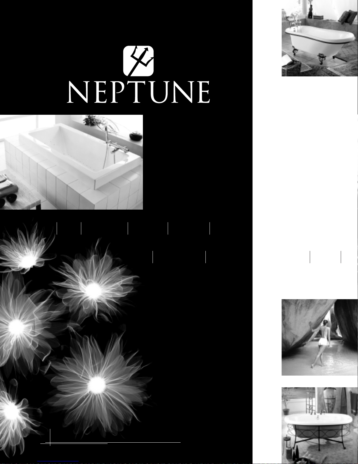
SITE PREPARATION
Plywood Floor
Drain
centre
15cm
6"
3
0cm
12"
Shims
Mark studs
Pencil
mark
1" x 2" support
M
o
r
t
a
r
Pencil outline of feet
• The site should be cleared of debris and vacuumed. This will
ensure that the bath is leveled properly and that no dir
sucked into the bath’s systems preventing possible damage.
• The floor should be checked for level and solidness. The level
should be in a range that can be compensated for by the use of
adjustment shims. An average sized bath can weigh as much as
450 kg (1000 lbs) when full, the floor must be able to support
this weight.
• An opening of 1 5cm x 3 0cm (6” x 12”) needs to be cut into the
floor for the bath drain and over
flow
(see fig.1). Make sure that
there are no obstructions in this space.
Fig. 1
t can be
ep 3:
• St
lip of the deck
Using a pencil mark the wall studs directly under the
(see fig. 2). If you intend to set the bath in a
mortar bed the position of the feet should be marked too.
Fig. 2
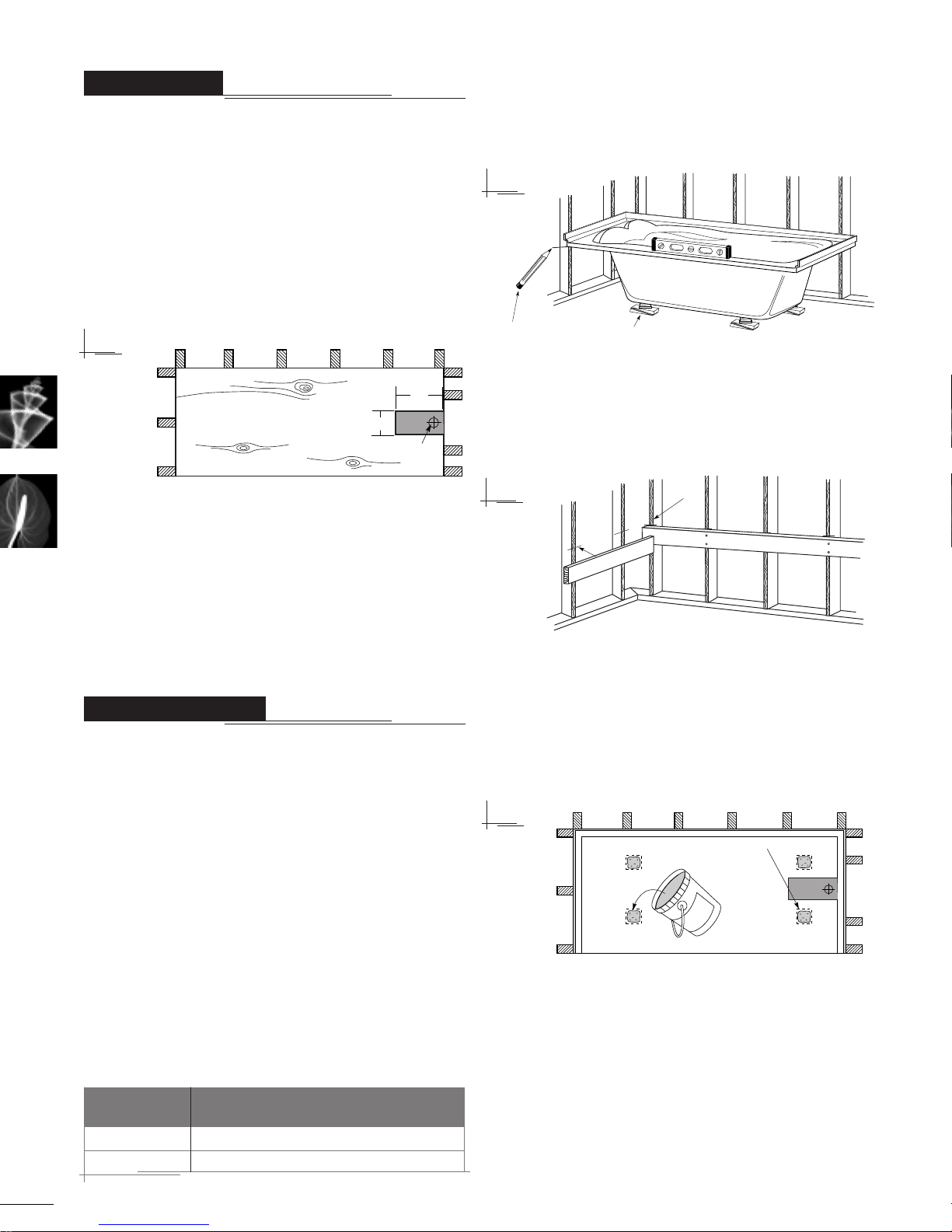
• Step 4: Remove the bath so that you have access to the walls.
•
Step 5: Cut supports for the bath deck from 1”x 2” stock.
The supports should be long enough to support the entire
length of the bath. These supports are fastened to the wall
studs with the top of the support at the level of the marks from
step 2
(see fig. 3).
• The plumbing rough-in for both the drain and the supply lines
should be completed by a competent and accredited plumber
before the bath is moved into its final position.
• For baths equipped with a Whirlpool, Mass-air , Activ-air , Lighting system or inline water heater all electrical connections should be completed by a competent and accredited electrician. Each system
must be hooked-up to a dedicated 15 amp ground fault circuit
interrupter (GFCI) breaker, or where allowed by law to a regular
breaker with a ground fault circuit interrupter (GFCI) outlet.
RECESSED INSTALLATION
When the plans call for installation of the bath in a recess (i.e.
encased between 2 or 3 walls) we suggest that the following
installation procedure be followed:
• Step 1: The bath overflow and drain should now be installed by
a competent certified plumber according to the overflow manufacturers instructions, and conforming to local building codes.
• Step 2: The bath should be set in position and leveled using
adjustment shims under all of the bath’s feet. Some baths are
equipped with adjustable metal feet and can be adjusted by
rotating each foot to the desired height. The bath should be
leveled long
deck closest to the wall
front to back by adjusting the shims under the front feet.
installing the optional bath skir
baths, the bath must be installed at the specific heights
shown in
Table 1
BATH TYPE lip to the top of the finished floor (ceramic tile)
Helena
Daphne 46 cm (18”)
4
itudinally first, by placing a long level along the bath
(see fig. 2). It can then be leveled from
t for Helena and Daphne
table 1.
INSTALLATION HEIGHT FOR SKIRT, under bath
46 cm (1
8”)
When
Fig. 3
Step 6: Mortar bed (optional, recommended for tub/shower
•
installations and baths with an integral skirt.)
NOTICE: When
using mortar to support a bath equipped with a Mass-air
system, the mortar should be under the feet only. Under no
circumstances should the mortar come into contact with
the piping and fittings underneath the bath.
tar should now be placed on the floor where the bath’s feet
mor
will land (marked out in step 2)
Fig. 4
•
Step 7: Apply a generous bead of construction adhesive along
the top of the 1”X2” suppor
t strips
(see fig. 4).
(see fig. 5). T
Freshly mixed
his will prevent
the bath from shifting and also compensates for the uneven
ness of the fiberglass reinforcement under the deck.
•
Step 8: Set the bath into position. Check that the bottom of
the deck comes into contact with the suppor
opted to use a mortar bed
, check that the mortar has
t strips.
If you
squeezed out and that the feet are supported. Add more
tar if necessary
mor
.
If you did not use a mor
tar bed
, the shims
should be replaced under the feet, and glued in place with construction adhesive.
-
45
°
S
ilicone
Silicone
Press this edge first
Rotate
Squishes
outexcess
t
o rear
Tape
Ad
h
e
sive
41cm max
16"max
* leave
enough
space
T
ile
2" x 3" structure
Plywood
Silicone
Fig. 5
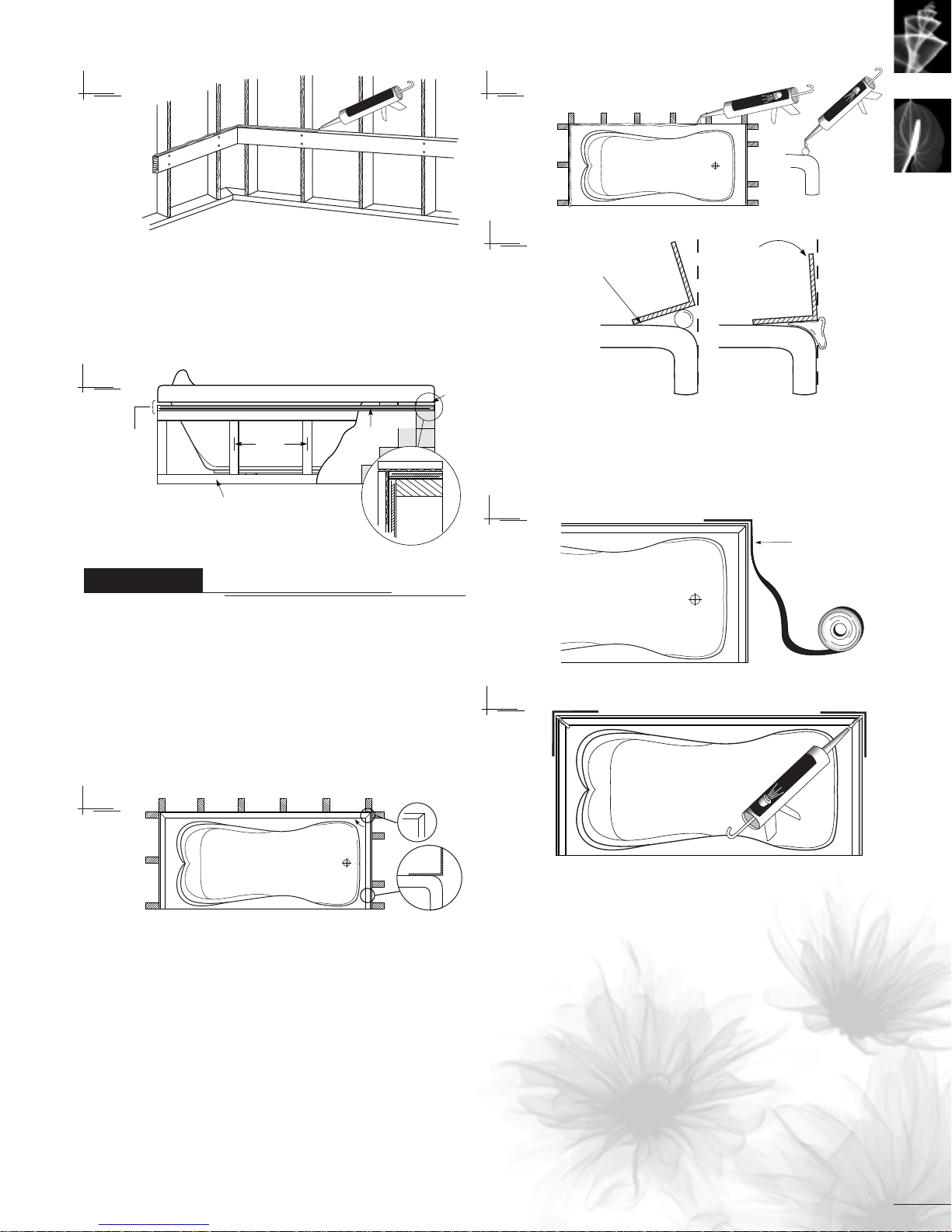
• Step 9: If your bath is not equipped with an integral skirt the
front wall should now be built. It is made from 2”x 3”s spaced
41cm (16”) on center
(see fig. 6). Remember to leave
enough space between the top of the wall and the bottom
of the bath deck to allow for installation of the plywood and
the ceramic tile or other covering material.
Fig. 6
Fig. 8
Fig. 9
ep 5:The mitered joints should be held closed by applying a
•St
short length of masking tape to the outside of the joint
10)
The joint should then be sealed from the inside by applying
a small bead of silicone in each of the miters
Fig. 10
(see fig. 11).
(see fig.
TILING FL ANGE
(optional, for recessed installation
Although many Neptune baths are designed with an integral tiling
flange occasionally the bathroom plans will call for the installation of
a podium style bath between either two or three walls. In such
instances it is highly recommended that an aluminum tiling-flange
(1/2”x 1/2” angle 1/16
installed option from your Neptune dealer or you can add your own.
•
Step 1: Using a miter box and hacksaw cut the tiling flange to
the lengths required. At the corners where the flanges meet the
cuts should be made at 45
Fig. 7
• Step 2: Where the tiling flange comes into contact with the bath,
faces of both the flange and the bath should be cleaned
the sur
with denatured alcohol.
•
Step 3: Apply a thin bead of bathroom grade (mildew resistant)
silicone along the perimeter of the bath where the tiling flange
is to be installed. Care should be taken not to use too much as
it could squeeze out onto the deck of the bath when the tiling
flange is positioned
•
Step 4: Beginning with the center strip (for three sided applications) set the tiling flange into the silicone. By depressing the
front of the flange first you will ensure that the excess silicone
squeezes out towards the rear and not onto the deck of the bath
(see fig. 9). Repeat this procedure for the remaining pieces.
th
thick) be installed. This is available as an
0
angles (see fig. 7).
(see fig. 8).
of a podium style bath)
Fig. 11
5
 Loading...