

Page 1
500-S and 500-VS
NEP-ZL105638
INSTALLATION
OPERATION &
MAINTENANCE
NEPTUNE
SERIES 500/5000
PUMPS
Model 500/5000
500-A, 500-D, 500-E,
03.2018_REV 7
Page 2

WARNING
SAFETY INSTRUCTIONS:
LOCKOUTS ARE REQUIRED BEFORE
SERVICING THIS EQUIPMENT.
Shut off/Lockout pump Power before Servicing.
Be certain pump isolation valves are
Closed and chemical is shut off.
Bleed pressure before servicing.
Page 3

EQUIPMENT MISUSE HAZARD
Equipment misuse can cause the equipment to rupture, malfunction and result in serious injury.
• This equipment is for professional use only.
• Do not allow pump to run dry.
PRESSURIZED EQUIPMENT HAZARD
• Shut off the pump and depressurize before performing any maintenance.
vacuum system. Take proper care to clean and handle them.
FIRE AND EXPLOSION HAZARD
Improper grounding, poor air ventilation, open flames, or sparks can cause a hazardous condition and result in fire or explosion and serious injury.
• Ground the equipment. See motor installation instruction for grounding procedure.
the pump.
TOXIC FLUID HAZARD
Hazardous fluids or toxic fumes can cause serious injury or death if splashed in eyes or on the skin, swallowed, or inhaled.
• Know the specific hazards of the fluid you are using. Read the fluid manufactures warnings.
diaphragm pump. Also oil vapor may breathe out of the air breather installed on the gear box.
SOUND HAZARD
The sound pressure level of the pump may exceed 80dBA in some of the pumps.
• Observe all safety precautions when operating the pump within close proximity for extended periods by wearing hearing
other effects such as loss of balance and awareness.
MECHANICAL HAZARD
The pump may shake or vibrate during operation.
WARNING
Please read thoroughly before installation, operation or maintenance of any Neptune pump
• Read all instruction manuals, tags, and labels before operating the equipment.
• Use the equipment only for its intended use.
• Do not alter or modify this equipment.
• Be certain all operators of this equipment have been trained for safe working practices, understand it's limitations, and wear safety
goggles and or equipment when required.
• Do not exceed the maximum working pressure of the system as mentioned on the pump tag.
• Do not use the pump head or the suction or discharge piping to pull the equipment.
• Do not move pressurized pump.
• Use fluids or cleaning agents for cleaning that are compatible with the pump parts. Read the fluid and cleaning agent manufactures
warnings and also refer to the material compatibility chart
• Comply with all applicable local, state and national safety regulations.
Spray from leaks or ruptured components can splash fluid in the eyes or on the skin and cause serious injury.
• Do not tamper with or perform unspecified alteration of this device.
• Use only pipe, hose, and hose fittings rated for maximum rated pressure of the pump or the pressure at which the pressure relief
valve is set at.
• Always wear protective clothing, face shield, safety glasses and gloves when working on or near your metering pump.
• Additional precautions should be taken depending on the solution being pumped. Refer to SDS precautions from your solution
supplier.
• Do not stop or deflect fluid leaks with your hand, body, glove, or rag.
• Tighten all fluid connections before operating the equipment.
• Replace worn, damaged, or loose parts immediately.
• Before performing any maintenance requiring pump head and or valve (wetted parts) disassembly, be sure to relieve pressure from
the piping system and where hazardous process chemicals are present.
• Make the pump safe to handle for the personal and the environment by cleaning and chemically neutralizing the pump as
appropriate.
• Wear protective clothing and use proper tools as appropriate to avoid any injury.
• If the diaphragm has failed, process chemical may have contaminated the pump hydraulic oil. Handle with appropriate care. Clean
the pump and replace oil as necessary. Discard the contaminated oil as per the local code.
• If the diaphragm fails in a double diaphragm pump, pressurized process chemical can be present in the Neptune leak detection
• Do not pump non recommended flammable or explosive fluids.
• Static electricity may generate by fluid moving through pipes and hoses. A static spark could be produced by high fluid flow rate.
Earthing of the pump is a must.
• Provide fresh air ventilation to avoid the possible buildup of flammable fumes from the process chemicals.
• Keep the pump area free of debris, including cleaning agent, rags, and any flammable material.
• Follow the cleaning agent and other cleaning recommendations as mentioned in the operation and instruction manuals.
• Use cleaning agent with the highest possible flash point to clean the pump parts if needed.
• If there is any static sparking while using the equipment, stop operation at once. Identify and correct the problem before starting up
• Store hazardous fluid in an approved container. Dispose of hazardous fluid according to all local, state and national guidelines.
• Wear the appropriate protective clothing, gloves, eyewear and respirator.
• Pipe and dispose of the exhaust air safely. If diaphragm fails, the fluid may be exhausted along with the air in mechanical
protectors.
• Extended exposure to elevated sound levels will result in permanent loss of hearing acuteness, tinnitus, tiredness, stress, and
Page 4

TABLE OF CONTENTS
SECTION
PARAGRAPH
PAGE
I
—
GENERAL DESCRIPTION
1
LIMITED WARRANTY
2
PARTS ORDERING INSTRUCTIONS
3
II
—
INSTALLATION INSTRUCTIONS
4
1.0
GENERAL 4
2.0
SUCTION PIPING
5 3.0
DISCHARGE PIPING
6 4.0
ADJUSTMENT OF INTERNAL RELIEF VALVE
6 5.0
INSTALLATION OUTDOORS
8 6.0
START-UP, FLOODED SUCTION
8 7.0
START-UP, SUCTION LIFT
9 8.0
START-UP, AFTER SUCTION HAS RUN DRY
9
III
—
NORMAL MAINTENANCE AND
10
DISASSEMBLY INSTRUCTIONS
9.0
MAINTENANCE
10 10.0
REMOVAL OF VALVE CARTRIDGES
11 11.0
CLEANING OF VALVE CARTRIDGES
11 12.0
REPLACING OF VALVE CARTRIDGES
11 13.0
PROCEDURE FOR REPLACING CONTROL
12
ROD AND SEALING PLATE “O” RINGS
14.0
REMOVAL OF PUMP HEAD AND
13
REPLACEMENT OF DIAPHRAGM
15.0
REMOVAL OF STANDARD MOTOR
14
IV
16.0
MOTOR OPERATING CONDITIONS
15
V
—
TROUBLESHOOTING CHART
16
VI
—
INSTRUCTIONS FOR PUMPS WITH
18
ELECTRIC STROKE CONTROL
VII
18.0
PARTS LIST
19
VIII
—
DRAWINGS
22
APPENDIX
—
ADDITIONAL INSTRUCTIONS FOR VARIOUS MODEL OPTIONS
SERIES 500-E-AR “dia-PUMP”
25
SERIES 500-E “dia-PUMP”
26
SERIES 500-A “dia-PUMP”
22
SERIES 500-VS “dia-PUMP”
29
SERIES 5000 “dia-PUMP”
30
DOUBLE DIAPHRAGM OPTION
32
Page 5
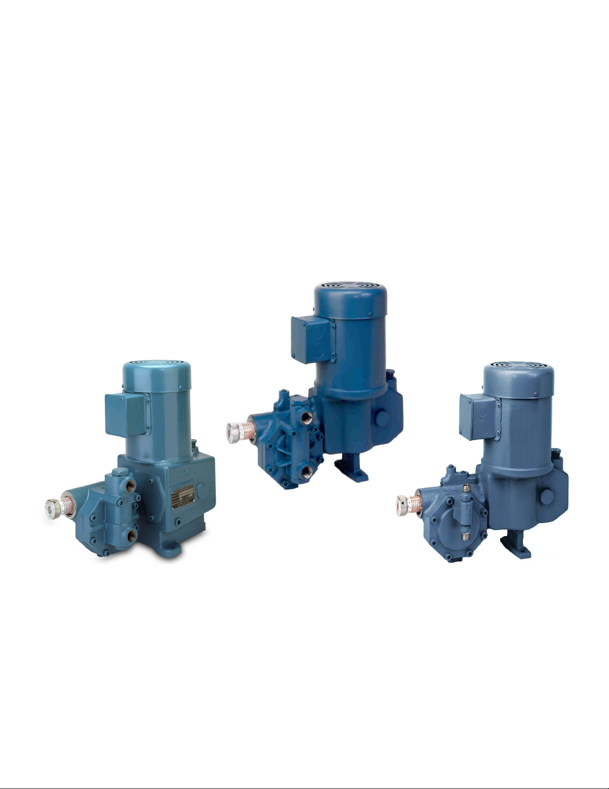
SECTION I
SERIES 500-E “dia” PUMP
WITH INTEGRAL TEFC MOTOR
SERIES 500-A “dia” PUMP
WITH INTEGRAL TEFC MOTOR
SERIES 500 “dia” PUMP
WITH INTEGRAL TEFC MOTOR
GENERAL DESCRIPTION
The Neptune Series 500 “dia-PUMP” is a reliable metering pump of the high-pressure diaphragm type. Under constant
conditions of temperature, pressure, and capacity adjustment settings, a +/-1% metered discharge volume is
maintained.
A plunger reciprocating at a fixed stroke displaces hydraulic fluid, which actuates a flexible, chemically inert, Teflon
diaphragm to create pumping action. The capacity of the pump is regulated by controlling the volume of hydraulic fluid,
which bypasses the diaphragm cavity.
Capacity adjustment can be made manually or automatically by instrument signal.
Metering accuracy is maintained by a control rod, which allows hydraulic fluid replacement and air venting automatically
with each stroke, while also taking into account temperature changes of the hydraulic fluid. Metering accuracy is also
insured by the use of double ball check valves on the suction and discharge of the pump.
PLEASE READ THE INSTRUCTION MANUAL COMPLETELY BEFORE INSTALLING THE PUMP.
®
The text and illustrations in the main body of this manual are based upon the Series 500 pump, shown at left above. The
Series 500-A and 500-E pumps are very similar to the Series 500 pump. The liquid ends are interchangeable.
Please refer to Appendix for all Models other than 500-S or 500-D.
Models 500-A, 500-E, 500-E-AR, 500-VS, 5003, 5005 and the Double Diaphragm Option are described in the Appendix.
1
Page 6

IMPORTANT NOTICE
SECTION I
NEPTUNE CHEMICAL PUMP COMPANY
LIMITED WARRANTY
All Neptune Pumps are tested at the factory prior to shipment. Each part used in their construction has been carefully
checked for workmanship.
If the pump is installed properly, Neptune Chemical Pump Company warrants to the purchaser of this product for a
period of three years from the date of shipment, this product shall be free of defects in material and/or workmanship, as
follows:
1. Neptune Chemical Pump Company will replace, at no charge, any part that fails due to a defect in material and/or
workmanship during the warranty period, FOB our factory, North Wales, Pennsylvania. To obtain warranty service,
you must forward the defective parts to the factory for examination, freight pre-paid.
2. This warranty period does not cover any product or product part, which has been subject to accident, misuse, abuse
or negligence. Neptune Chemical Pump Company shall only be liable under this warranty if the product is used in the
manner intended by the manufacturer as specified in the written instructions furnished with this product.
Any express warranty not provided in this warranty document, and any remedy for breach of contract that, but for this
provision, might arise by implication or operation of law, is hereby excluded and disclaimed. Under no circumstances
shall Neptune Chemical Pump Company be liable to purchaser or any other person for any charge for labor, repairs, or
parts, performed or furnished by others, nor for any incidental consequential damages, whether arising out of breach of
warranty, express or implied, a breach of contract or otherwise. Except to the extent prohibited by applicable law, any
implied warranty of merchantability and fitness for a particular purpose are expressly limited in duration to the duration of
this limited warranty.
Some states do not allow the exclusion or limitation of incidental or consequential damages, or allow limitations on how
long any implied warranty lasts, so the above limitations may not apply to you. This warranty gives you specific legal
rights, and you may have other rights, which may vary from state to state.
1
IMPORTANT
SHOULD IT BE NECESSARY TO SEND THE PUMP TO THE FACTORY FOR REPAIR OR MAINTENANCE
REBUILDING; DRAIN ALL OIL AND CHEMICAL FROM PUMP BEFORE SHIPPING. FAILURE TO DO SO CAN
CAUSE EXTENSIVE DAMAGE TO THE MOTOR.
1
SEE IMPORTANT NOTICE - RETURN GOODS AUTHORIZATION
RETURN GOODS AUTHORIZATION
(1) All equipment returned to Neptune Chemical Pump Company, Inc. requires proper Returned
Goods Authorization Number (RGA) and tags.
(2) All equipment returned to the factory for repair or service must first be thoroughly flushed and have
all chemical contact areas neutralized.
(3) All equipment, which has been in contact with chemicals, must be accompanied by a copy of the
chemical product material Safety Data Sheet (SDS).
(4) Failure to comply with the above instructions will result in equipment being returned to sender,
freight collect, without service.
2
Page 7

PARTS ORDERING INSTRUCTIONS
The complete model number and serial number of the pump must be furnished to insure prompt and
accurate parts service. These numbers are found on the name plate (sample below) located on the side of
the pump. Refer to Section VII for complete parts lists.
Send all orders or inquiries for parts to:
Parts Department
Neptune Chemical Pump Company
295 Dekalb Pike
North Wales, PA 19454
Tel.: 215-699-8700
1 -888-3NEPTUNE (888-363-7886)
FAX: 215-699-0370
Web: www.neptune1.com
Email: neptune.sales@psgdover.com
NOTE: PLEASE SUPPLY BOTH MODEL AND SERIAL NUMBERS.
3
Page 8

SECTION II
INSTALLATION INSTRUCTIONS
1.0 GENERAL
1.0.1 When unpacking a pump or chemical feed system, be certain that no parts are thrown away.
Examine the equipment for possible damage. If damage has occurred, file claim with the common
carrier within 24 hours. Neptune will assist in estimating the repair costs.
1.0.2 The ‘‘dia-PUMP’’ should be located so as to avoid an ambient temperature above 120°F, 50°C. Free
air circulation is important when considering the location of the pump.
1.0.3 The ‘‘dia-PUMP’’ should be located on a level surface. Three mounting holes are provided to anchor
the pump securely to the mounting surface. PVC head pumps must be mounted on three, one-inch
spacers provided.
1.0.4 Neptune recommends a 4” to 6” inch clearance above mounting surface (on most models) to allow
access to the Suction Valve. Please refer to model and valve location prior to installation.
1.0.5 All piping to the pump should be supported to prevent stress on the pump input and output fittings.
1.0.6 Before connecting the pump, make sure that all fittings are completely clean by flushing thoroughly.
Any foreign matter entering the pump can damage the internal parts and severely limit the life of the
pump.
1.0.7 A ‘‘Y’’ STRAINER MUST BE INSTALLED IN THE SUCTION LINE OF THE PUMP TO INSURE
AGAINST FOREIGN MATTER ENTERING THE PUMP. ALL SUCTION LIFT APPLICATIONS
REQUIRE A FOOT VALVE STRAINER TO PREVENT LOSS OF PRIME, AND TO PREVENT
FOREIGN MATERIAL FROM ENTERING THE PUMP.
1.0.8 Shut-off valves and unions should be placed in the suction and discharge lines to facilitate servicing
the pump.
1.0.9 Care should be exercised when piping to PVC head pumps. In cases where vibration or stress is
unavoidable, flexible connections should be used.
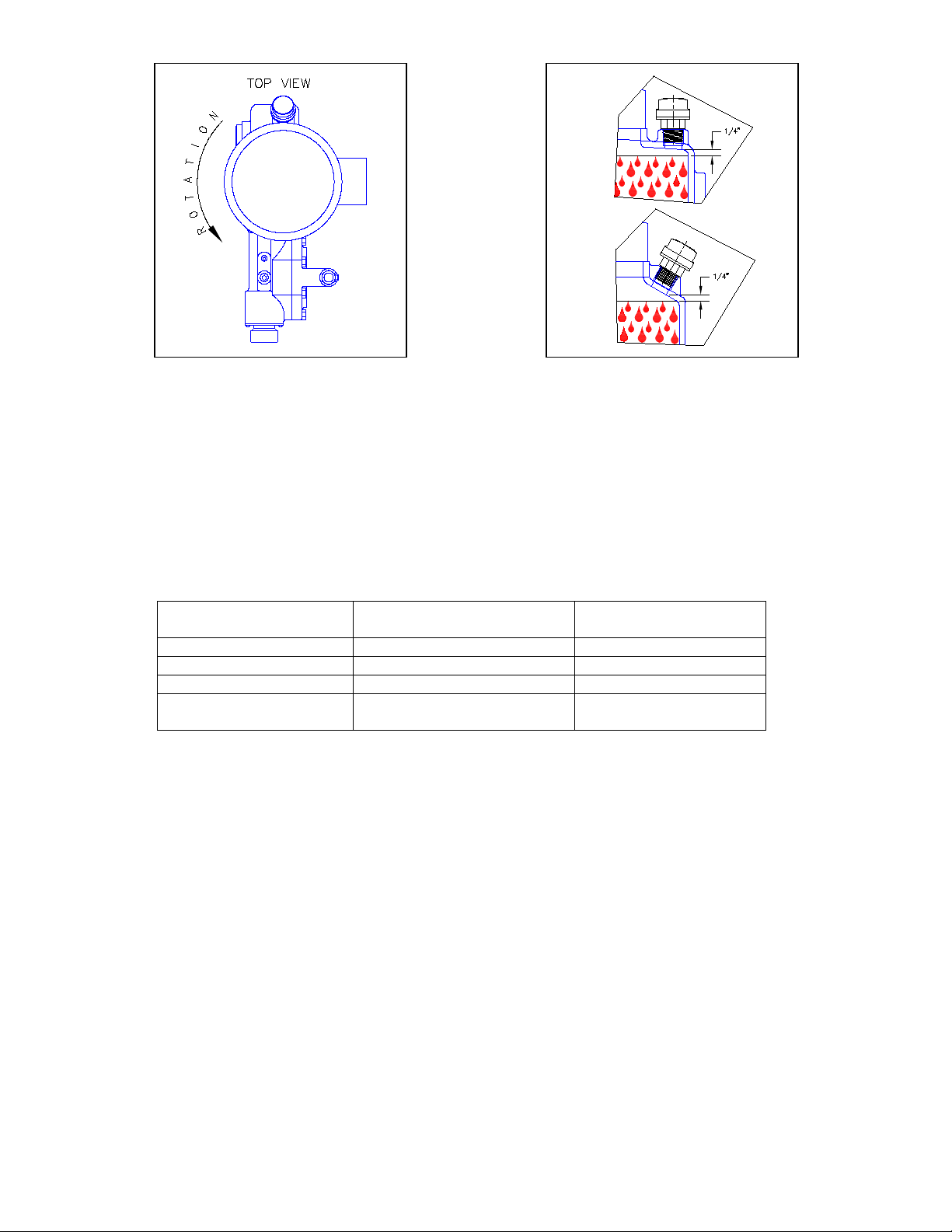
1.0.10 The electrical supply to the pump must match the motor name plate characteristics. The motor
rotation is counter clockwise when viewed from the top of the motor, looking down on the pump. (See
Figure 1).
1.0.11 Discharge Piping should be the same size or larger than the discharge connection. Suction Piping
should be one size larger than the suction connection (1/2” pipe minimum). Limit the total length of
the suction line to 3-4 feet suction lift or 6-7 feet flooded suction. Minimum bends, elbows, or other
restrictions.
Important
On single phase integral motors, the rotation is set at the factory and must not be changed.
On three phase integral motors, rotation is determined by noting the fan rotation.
Pump body is grounded to earth. Ground connection MUST penetrate to bare metal. Ground
to be clearly marked.
Check external pressure relief valve setting.
On some flange mounted motors, the motor rotation may be viewed by removing the cap on
the side of the flange. There is no viewing port or coupling access on the close coupled flange
mount motors. Rotation is checked by removing the oil fill plug an observing the gear. Correct
rotation is indicate by the gear teeth moving downward away from the oil fill hole.
Please note Figure 1, indicating the correct rotation. (An arrow on the gear box also indicates
proper rotation.) Operation with the incorrect rotation will damage the pump and motor.
Models 5003 and 5005 must be installed with a flooded suction. These models will not operate with
suction lift.
4
Page 9
Alternate
Oils For Standard
Mfg.
Alternate
High Pressure Oils
Mobil Gear #626
Mobil Oil
Mobil Gear #629
Sun EP #68
Sun Oil
Sun Oil #220
Meropa #68
Texaco
Meropa #220
Mobil 1 0W30/5W30 for
5003/5005 Pumps only
Mobil Oil
FIGURE 1A
FIGURE 1
OIL LEVEL.DWG
1.0.12 Set capacity knob to zero and remove Air Bleed Plug from the top of Oil Chamber, refer to drawings HP-1102 (page 22)
for Series 500 and drawing 5024 (page 28) for Series 500-A and 500-E for location of plug. Fill gear box and pump by
pouring the hydraulic fluid supplied through the fill opening at the rear of the pump. Pour fluid in slowly until it has
reached the correct level per Figure 1A. Do not over fill as this can cause damage to the motor.
Allow a few minutes for the hydraulic fluid work through the oil head and appear at the oil bleed plug. Recheck oil level.
When air is purged, reinstall the Air Bleed Plug.
The hydraulic fluid supplied by Neptune is:
EP 68 Gear Oil, consult the parts listing in the back of this manual for the Neptune part number.
Heavier hydraulic fluid is supplied by Neptune for Hi Pressure Systems is EP SAE 90.
The 90 weight gear oil is used for high-pressure pumps using 1/2 horsepower motors or larger and rated for operation
over 1000 PSI except 5003 and 5005 pumps which uses Mobil 0W30 synthetic oil.
The 90-weight gear oil is also provided for the 500 pump models at all pressures.
2.0 SUCTION PIPING
2.0.1 The suction piping to the pump must be absolutely air tight. It is suggested that the suction piping be tested with
low air pressure and a soap solution to assure that no leaks exist.
2.0.2 NEPTUNE RECOMMENDS THAT THE ‘‘dia-PUMP’’ BE OPERATED WITH A FLOODED SUCTION, AS THIS
WILL FACILITATE START UP AND INCREASE THE SERVICE LIFE OF THE PUMP. It is, however, possible to
operate the ‘‘dia-PUMP’’ with a suction lift of up to 5 feet, if absolutely necessary. A FOOT VALVE STRAINER
must be used on this type of application. Model 5003 and 5005 require a flooded suction.
2.0.3 It is highly recommended that all solution tanks be furnished with a low level cut off switch or low level alarm and
cut off switch to prevent the pump from running dry. OPERATION AGAINST A DRY SYSTEM WILL CAUSE
DAMAGE TO THE PUMP DIAPHRAGM AND REDUCE THE OPERATING LIFE OF THE PUMP.
2.0.4 The single, safest rule of thumb for selecting suction pipe size is to use the same size or one size larger than
the pump suction connection (1/2” pipe minimum).
5
Page 10
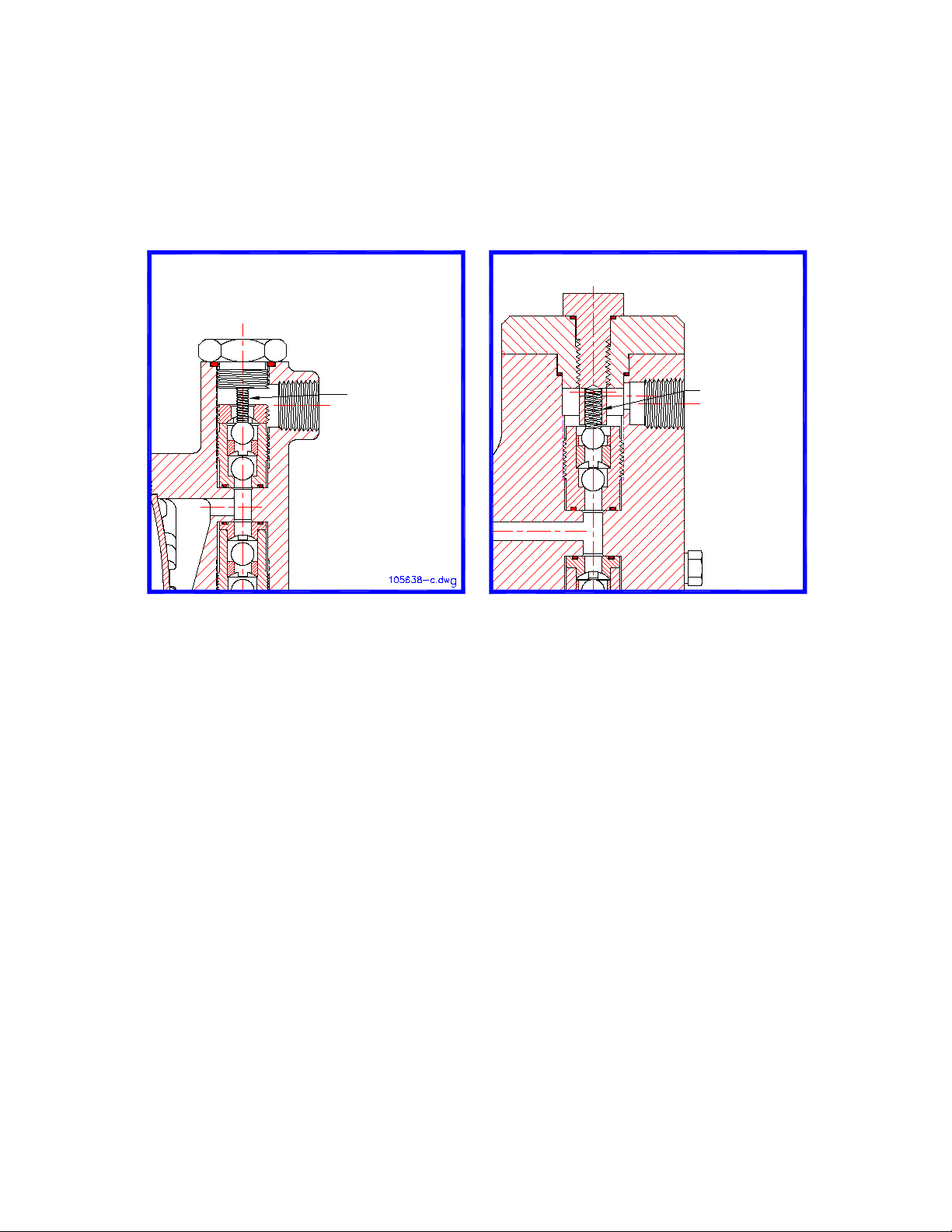
FIGURE II
FIGURE III
ANTI-SIPHON
SPRING
P/N 000257
ANTI-SIPHON
SPRING
P/N 100198
P/N 100199
3.0 DISCHARGE PIPING
3.0.1 It is recommended that the ‘‘dia-PUMP’’ operate against a minimum discharge pressure of 50 psig. A
back pressure spring is supplied loose with the pump. If 50 psig back pressure is not provided by the
application, the back pressure spring should be installed on the pin under the discharge valve cap.
Installation of the back pressure spring artificially creates a discharge head. (Refer to Figures II and
III.) Note: Spring is not provided in 500-E Series.
3.0.2 Take care to use piping suitable for the discharge pressure.
IN METAL HEAD PUMP
IN PVC HEAD PUMP
4.0 ADJUSTMENT OF INTERNAL RELIEF VALVE
4.0.1 All Neptune Series 500/5000 dia-PUMPs are supplied with an internal relief valve preset to 200 psi.
The internal relief valve is designed to protect the pump itself should a discharge pressure beyond the relief
valve setting occur.
If a customer order specifies a relief valve setting above those indicated above, the specified setting will be
set at the factory. All pumps are tagged with the relief valve setting used by the factory.
6
Page 11
4.0.1 (Continued)
FIGURE IV
4.0.2 To reset the relief valve to a higher pressure, (the relief valve setting cannot be reduced because of
To protect the external piping system, it is recommended that a relief valve as manufactured by
Neptune Chemical Pump Company, or equal, be placed in the discharge line of the pump. It is
further recommended that this relief valve be piped into return of the tank with clear PVC tubing so
that it can be determined if the solution is by-passing through the valve and returning to the tank,
indicating a line blockage.
Drawing HP-1102 (page 22) illustrates the location of the Internal Relief Valve for Series 500 (FIG.
#527 through #530). See drawing 5024 (page 28) for Series 500-A and 500-E.
The drawing shows a passage connecting the hydraulic fluid reservoir with the hydraulic fluid side of
the diaphragm.
The passage is interrupted by the Relief Valve Poppet (FIG. #527) which is backed up by a Relief
Valve Spring (FIG. #528).
If, during the pump operation, the pressure on the hydraulic fluid side of the pump exceeds the set
pressure of the internal relief valve, the poppet is forced from its seat allowing the hydraulic fluid to
flow back to the reservoir.
design considerations) instructions are as follows:
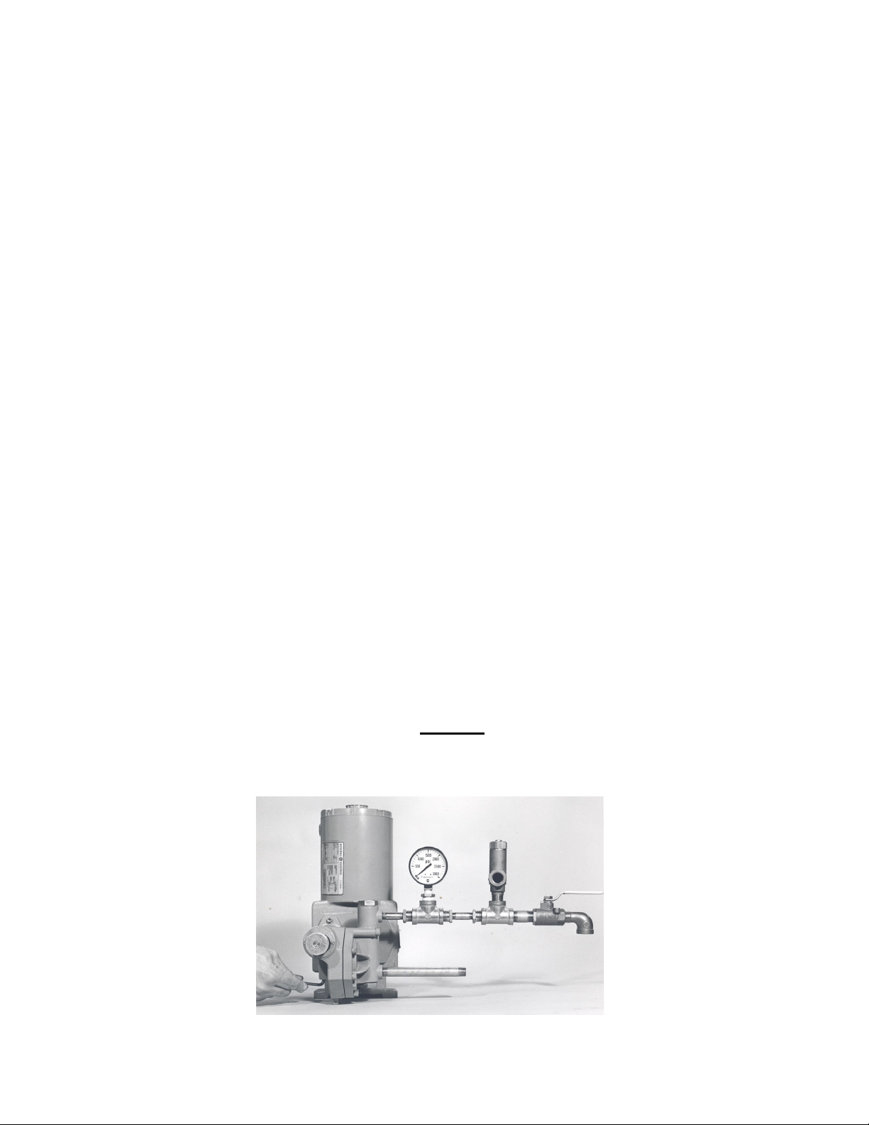
4.0.21 Connect a test set-up as shown in Figure IV below.
4.0.22 Start and run the pump until all air is relieved from the discharge liquid (hand valve open).
4.0.23 Remove Relief Valve Plug (Fig. #530).
4.0.24 Close hand valve; pressure gauge will read the internal relief valve setting which should
agree with the pressure setting on the tag if the pump is new. The desired setting is 100 psi
above the operating pressure of the system into which the pump is injecting. Do not adjust
lower than 200 psi.
4.0.25 To change the relief valve pressure setting, use the 3/16” Allen Wrench to adjust spring
tension by turning Relief Valve Adjusting Screw (FIG. #529).
(1) To increase pressure, turn Relief Valve Adjusting Screw (Fig. #529) in.
(2) To decrease pressure, turn Relief Valve Adjusting Screw (Fig. #529) out.
4.0.26 After resetting or adjusting pressure, replace Relief Valve Plug (Fig. #530).
Never turn Relief Valve Adjusting Screw (Fig. #529) completely in.
Do not attempt to set the internal relief valve more than 200psi in excess of name plate rating.
CAUTION
7
Page 12

4.0.3
1 Pc.
1/2” Pipe Nipple 6” Long
2 Pcs.
1/2” Pipe Nipple 2” Long
1 Pc.
1/2” Hand Valve
2 Pcs.
1/2” Tee
1 Pc.
1/2” NPT X 1/2” Hose (Fitting)
1 Pc.
1/2” Hose, As Required
1 Pc.
1/2” Pressure Gauge (Minimum Gauge Pressure 500 psi)
1 Pc.
Allen Wrench 3/16”
1 Pc.
External Relief Valve (optional)
Parts required to test or adjust Relief Valve Pressure.
NOTE
The above parts must have a working pressure rating above the required set pressure.
5.0 INSTALLATION OUTDOORS
The “dia-PUMP” is a totally enclosed pump which can be used outdoors or indoors. When installed outdoors, make sure
that the pump is protected against extremes of nature as follows:
5.0.1. Running of the pump when exposed to tropical sunshine, with ambient temperature above 100ºF, 38ºC would
cause excessive oil and motor temperatures. The pump should be shaded and located in such a way as to
permit a high degree of air circulation.
5.0.2 Under cold conditions, the pump should be insulated and a heater should be supplied in order to maintain the
hydraulic fluid at an ambient temperature above 30ºF, -1ºC. Heat may be provided by a 100 watt bulb or a
heater tape, etc.
6.0 START-UP PROCEDURE (FLOODED SUCTION)
The following start-up procedure is complete and does repeat instructions on filling the gear box and pump.
6.0.1 The gear box should be filled with hydraulic fluid per the instructions in paragraph 1.0.12. Let the pump stand for
30 minutes and then recheck fluid level. Be certain that pump discharge lines are open.
6.0.2 Confirm that the liquid head is flooded and no air remains per the following paragraphs. Pumps should not be
running. Wear appropriate protective gear when performing any step that involves contact with the chemical.
6.0.2.1 SERIES 500 and 500-A METAL HEAD
Make certain that pumping chamber is flooded and air is purged by loosening Discharge Valve Cap (FIG. #536
on page 22) approximately 2 to 3 turns and allowing solution to appear. Then, tighten discharge valve cap. This
procedure will also allow air to vent from pumping chamber. THE “dia-PUMP” WILL NOT FUNCTION IF AIR IS
TRAPPED IN THE HYDRAULIC FLUID OR LIQUID PUMP CHAMBERS.
PVC Head Pumps –Discharge Valve Cap (P/N 000256 on page 23) is loosened by loosening Valve Cap Screws
6.0.2.2 SERIES 500 AND 500-A PVC HEAD
(P/N 100250).
6.0.2.3 SERIES 500-E (See page 26)
6.0.3 Follow the procedure below:
1. Make certain that the suction line, liquid end and discharge cartridge chamber are filled with water or
system fluid.
2. Set the capacity control knob to approximately 30-40% of maximum capacity.
3. On initial start-ups: Check for proper motor rotation (Refer to Paragraph 1.0.11). Run the pump for 10-20
seconds, then stop for 20-30 seconds. Repeat a few times. During these short runs, listen for any abnormal
motor or crank noises, and if present, refer to Trouble Shooting Chart.
8
Page 13

4. On initial gearbox fill or after replacing hydraulic fluid, run pump for one-half to one hour to warm
up oil and allow air bubbles to dissipate. Check discharge line for indication of flow.
®Teflon – A registered trademark of the DuPont Company.
5. Once discharge flow is observed proceed to paragraph number 6; if no flow, repeat steps 3 and 4.
7.0 START-UP PROCEDURE (SUCTION LIFT) SERIES 500 AND 500-A.
(See page 26 for SERIES 500-E) MODELS 5003, 5005 AND 510 REQUIRE A FLOODED SUCTION.
Use the following procedure only if required:
8.0 START-UP AFTER SUCTION HAS RUN DRY
6. Increase capacity adjustment setting to 70% of maximum capacity and operate for 10-20 minutes.
7. Reduce capacity adjustment setting to 30-40% of maximum capacity and operate for several
minutes, then increase capacity adjustment back to 100% for approximately 10 minutes. Repeat
several times to insure that the air is bled from the hydraulic fluid side and the liquid side.
6.0.4 The pump is now ready for “on line” service. Calculate what the desired capacity as a percentage of
either the maximum capacity rating on the pump data plate, or the nominal capacity at the required
system pressure.
7.0.1 If the “dia-PUMP” is to be used where suction lift is required, A FOOT VALVE STRAINER MUST BE
INSTALLED on the end of the suction line. A pipe tee is installed on the top end of the suction line
with one leg to the pump suction, one leg to the suction line and one leg pointing straight up and
plugged. Remove plug and fill piping assembly with liquid. Replace plug. Start pump and follow
procedure per Paragraph 6.0.3.
7.0.2 Remove Discharge Valve Cap (FIG. #536). Then, using Allen wrench provided, remove Discharge
Valve Nut (FIG. #543). The Discharge Valve Nut (FIG. #543) is stamped with the letter “T” to indicate
the face which should be installed toward the top on reassembly. Finally, remove Discharge Valve
Cartridge (FIG. #539) using special blade provided. Fill the pumping chamber with liquid to check
operation of the suction valve. Reinstall / replace parts and then follow instructions per Section II,
Paragraph 6.0.3. Repeat entire procedure if pump loses prime or runs dry. (See Figures VI and VII.)
NOTE
PVC Head Pumps (Refer to page #23) – Remove Discharge Valve Cap (P/N 000256) by removing
Valve Cap Screws (P/N 100250). Next, remove Discharge Valve Cartridge (P/N 000259) using
special round lug tool provided. Fill pumping chamber with liquid to check operation of the suction
valve. Reinstall / replace parts and then follow instructions per Section II Paragraph 6.0.3. (Refer to
Figure VII.)
CAUTION
Do not over tighten PVC valves as the PVC material is not able to withstand excessive force and can
fail. Teflon® paste is an excellent thread lubricant and may be applied.
In applications where the suction tank does not have a low level cut-off interconnected into the pump
motor circuit, the pump may occasionally run dry. THIS MUST BE AVOIDED BECAUSE DAMAGE
TO THE PUMP CAN RESULT AND THE SERVICE LIFE WILL BE SIGNIFICANTLY REDUCED
WHEN THE PUMP IS ALLOWED TO RUN WITH A DRY LIQUID END.
Before restarting a pump that has run dry and which has not damaged itself, follow the procedure in
Paragraph 6.0 through 6.0.3 of Section II, except it is not necessary to warm up the oil.
9
Page 14

SECTION III
NORMAL MAINTENANCE AND DISASSEMBLY INSTRUCTIONS
Recommended Maintenance Schedule
Weekly Interval
• Check oil level
Check for leaks
Check ground connection for corrosion
• Clean pump surfaces and surrounding area of dust and debris
First 250 hours of operation
• Change oil
Every 4000 hours or six months
Change oil
• Clean inlet piping strainer & check external pressure relief valve
Replace worm shaft oil seal
If equipped, check coupling insert. Replace if necessary.
Tighten all fasteners
Annual
Clean check valves. Replace O-rings.
Replace diaphragm
• If equipped, replace coupling insert.
• Replace rolling element bearings
Replace O-rings
Replace check valves
9.0 MAINTENANCE
Under normal conditions, the “dia-PUMP” does not require any significant amount of maintenance. It is
advised that periodic visual observations be made of the oil level. See Page 5 (Figure 1A) for correct oil
level. The liquid end of the pump should also be inspected for leakage. These observations should be made
regularly, at least every 48 hours.
•
•
•
•
•
•
•
•
•
•
10
Page 15

10.0
REMOVAL OF VALVE CARTRIDGES (See page 26 for SERIES 500-E; Page 29 for 500-VS)
The “dia-PUMP” incorporates a unique check valve design whereas the discharge and suction piping NEED
NOT be disturbed in order to service the valve cartridges.
Should the valves need cleaning, remove as follows:
10.0.1 Suction Valve: Remove Suction Valve Cap (FIG. #550) and using Allen Wrench provided, remove
Suction Valve Cartridge (FIG. #544).
NOTE for PVC Head Pumps
Remove Suction Valve Cap (P/N 000256) by removing the Valve Cap Screws (P/N 100250) and
remove Suction Valve Cartridge (P/N 000259) using the special round lug tool provided. Caution:
PVC is fragile – do not use excessive force.
10.0.2 For removal of discharge valve, refer to instruction in Section II, Paragraph 7.0.2.
10.0.3 Please refer to Figures VI and VII showing valve cartridge removal.
11.0 CLEANING OF VALVE CARTRIDGES
11.0.1 The valve cartridge is a complete and integral unit and should not be disassembled for cleaning. If
the valves are found to be worn and in need of replacement, an entire valve cartridge, either suction
or discharge, should be ordered. The suction valve is the longer of the two valve cartridges.
11.0.2 To clean the valve cartridges, soak in strong detergent and then blow dry with compressed air.
12.0 REPLACING OF VALVE CARTRIDGES (See page 25 for SERIES 500-ER)
12.0.1
Be certain that the Valve Seat O-Ring (FIG. #549 for Metal Head Pumps, P/N 100185 for PVC Head
Pumps) is removed with the valve and that no other foreign matter is in the valve cavity.
Use a small amount of grease to hold the o-ring in the groove in the end of the valve cartridge on
reassembly.
Reverse the procedure used to remove the valve cartridge. Do not over-tighten valve cartridge. Firm
tightening is enough to cause the O-Ring to seal.
11
Page 16

FIGURE V
CUT-AWAY VIEW OF VALVE SECTION, METAL HEAD PUMP
FIGURE VI
VALVE CARTRIDGE REMOVAL, METAL HEAD PUMP
FIGURE VII
VALVE CARTRIDGE REMOVAL, PVC HEAD PUMP
12.0 REPLACING OF VALVE CARTRIDGES (Continued)
13.0 PROCEDURE FOR REPLACING CONTROL ROD O-RING (fig. #517)
AND SEALING PLATE O-RING (FIG. #516).
Refer to Figure VIII
1. Remove Drain Plug (FIG. #510) and drain hydraulic fluid.
2. Remove Indicator Plate (FIG. #520) by removing two holding screws.
3. Remove control rod assembly with Control Rod (FIG. #’s 515, 523,524) attached, by turning counter
clockwise and pulling out.
4. Insert 11/16” Hex Socket onto the Sealing Nut (FIG. #526) and screw out of pump in a counter clockwise
direction. Then, remove Sealing Plate (FIG. #518) using a small brass hook to pull loose.
12
Page 17

FIGURE VIII
REMOVAL OF CONTROL ROD ASSEMBLY
5. Replace Control Rod O-Ring (FIG. #517) and Sealing Plate O-Ring (FIG. #516).
Remove and examine Teflon Diaphragm (FIG. #533). Remove and examine the Liquid Side
6. Take care when replacing Sealing Plate, (FIG. #518) so as to not damage the Sealing Plate O-Ring
(FIG. #516).
7. Replace all parts and fill pump with hydraulic fluid per previous instructions.
8. Follow start-up procedure as if starting a new pump.
14.0 REMOVAL OF PUMP HEAD AND REPLACEMENT OF DIAPHRAGM (REFER TO FIGURES IX AND X)
14.0.1 Remove Drain Plug (FIG. #510), and drain hydraulic fluid.
14.0.2 Remove Long and Short Pump Head Bolts [(FIG. #’s 551 and 552) or (P/N 101135 and P/N 101136)
on PVC pumps.] Lift Pump Head [(FIG. #535) or (P/N 000255, P/N 000258) on PVC pump] away from
pump.
14.0.3
Diaphragm Backup Place [(FIG. #532) or (P/N 000254, 100245) on PVC pumps.] Replace with new
part, if required. When replacing the Teflon diaphragm, be certain to line it up properly with the sealing
grooves.
14.0.4 To reassemble, reverse the above procedure. Reassembly is facilitated by laying the pump on its side.
Be certain to tighten all bolts evenly. Tighten to 25 ft. lbs. (15ft. lbs. On PVC pump).
14.0.5 Start up pump by following Start-Up Procedure per Section II Paragraph 1.0.12 and 6.0.3.
13
Page 18

14.0 REMOVAL OF PUMP HEAD AND REPLACEMENT OF DIAPHRAGM (Continued)
FIGURE IX FIGURE X
15.0 REMOVAL OF MOTOR FROM STANDARD “dia-PUMP” (REFER TO FIGURE XI)
15.0.1 Disconnect all wires leading to the motor.
15.0.2 Remove Drain Plug (FIG. #510) and drain hydraulic fluid from pump.
15.0.3 Remove the fan cover and fan if the motor is a TEFC type. Remove retaining bolts from the top of the motor.
These bolts are threaded directly into the Pump Gear Box (FIG. #500).
15.0.4 Turn case of motor gently to break silicone seal between motor casing and Pump Gear Box (FIG. #500). Tilt
motor slightly forward and remove housing and remove internal part.
15.0.5 To replace motor, clean machined surface at top of Gear Box (FIG. #500) and apply silicone sealer. Place
motor back in position generally reversing the disassembly procedure.
FIGURE XI
14
Page 19

SECTION IV
in thermal
MOTOR OPERATING CONDITIONS
16.0 The Standard Series 500/5000 “dia-PUMP” is supplied with a 1/3 HP or 1/2 HP/single phase/totally enclosed fan cooled
motor as an integral part of the pump itself.
The normal temperature rise for this motor is 40ºC above ambient temperature and thus, it might appear that the motor is
operating at a higher than normal temperature. This situation is normal and should not cause concern.
As a precaution against motor overheating, it is recommended that the pump be located where adequate ventilation is
available. It is also highly RECOMMENDED THAT A MOTOR STARTER WITH THE PROPER OVERLOAD
PROTECTION BE SUPPLIED AS AN ADDITIONAL SAFETY DEVICE.
The Standard Series 500/5000 “dia-PUMP” (1/3HP/1/115V/60C/TEFC) motor is supplied with builtprotection. Automatic overload is provided on all pumps with standard motor with serial numbers higher than 9600-78D.
Should an overload occur on a standard motor unit which is not protected by a motor starter or on such a unit where the
starter has failed, the motor will shut down automatically. It will take approximately ½ hour for the automatic thermal
overload switch to reset itself.
15
Page 20

SECTION V
TROUBLESHOOTING CHART
1. Pump Motor Will Not Operate.
A. Blown Fuse.
A. Check for short circuit or overload.
B. Open thermal overload device in
B. Reset.
C. Low liquid level in tank (where low
C. Fill tank.
D. Broken wire.
D. Locate and repair.
E. Low voltage.
E. Check for too light wiring.
F. Oil “frozen” in pump.
F. Thaw out.
*2. Pump Does Not Deliver Rated
A. Starved suction.
A. Replace suction piping with larger size,
B. Leaky suction piping.
B. Pressure test, repair or replace
C. Excessive suction lift.
C. Rearrange equipment location to
D. Liquid too close to boiling point.
D. Lower temperature or increase suction
E. Air or gas trapped in oil or pumpage.
E. Decrease capacity to 20% for 5 mins.,
F. Worn or dirty valves or seats, or both.
F. Clean or replace.
G. Viscosity of liquid too high (CPS).
G. (1) Reduce viscosity by heating or
H. Insoluble materials settling out, or
H. Check solution strength.
I. Low discharge pressure.
I. A minimum discharge pressure of 50
J. Capacity adjustment set above 100%
J. Reposition adjustment knob to 100%
K. Air in hydraulic or chemical systems.
K. Bleed system.
SYMPTOMS CAUSES REMEDIES
starter or motor.
Capacity
level cut-off is used).
or increase suction head.
defective piping.
reduce suction lift.
head pressure.
then increase to 100% for 5 mins.
other means;
(2) Increase size of suction piping;
(3) Increase suction pressure
crystallization of saturated solution.
capacity mark.
16
Flush and clean solution tank
periodically. Suction connection should
be 2 to 4” from bottom of solution tank.
psi is required to insure proper capacity
control.
mark.
Page 21

SYMPTOMS CAUSES REMEDIES
L. No foot valve strainer.
L. Install one.
*3. Pump delivers erratically.
A. Leaky suction line.
A. Repair or replace piping.
B. Worn or dirty valves or seats, or
C. Excessive excursion of ball from
D. Liquid too close to boiling point.
D. Reduce temperature or raise
suction pressure.
E. Leaky internal or external relief
4. Motor Overheats Thermal
A. Overload caused by operating
A. Check operating pressure against
5. Noisy Operation
(1) In Pump
A. Pump Valves.
A. Valves must move to open and
(2) In Gear Reducer
A. Pounding noise at high discharge
A. Fluid compressibility causes
6. Improper Oil Level in
A. Increases and overflows.
A. Flexible diaphragm punctured by
7. Pump Delivery is Not
A. System pressure too low.
A. Install back-pressure spring,
8. Pump Does Not Develop
A. Internal relief valve leaking.
A. Check setting as per pressure
B. Internal relief valve being
B. System pressure exceeds relief
Overload Activates
both.
valve seats (indicated by ball
chatter).
valve.
pump beyond rated capacity.
pressure.
B. Clean or replace cartridges.
C. Replace cartridges.
E. Repair or replace relief valve.
pump manufacturer’s data plate
maximum rating.
close, and they will make a clicking
noise as they operate. These
noises are sometimes amplified by
natural resonances in piping
system. They are usually
indications of normal valve
functioning.
reversal of load on gears at end of
pressure stroke. Not considered
detrimental.
Reservoir.
Adjustable
Required Pressure
* Symptoms 2 and 3 ---- A Diaphragm may need replacing.
actuated.
foreign material – replace
diaphragm. Clean and flush
hydraulic system at once.
provided, into discharge cartridge.
B. Install Back-pressure valve.
change procedure, Paragraph 4.0.
valve set pressure.
Refer to Paragraph 4.0 for
adjustment procedure.
17
Page 22

SECTION VI
SEE ELECTRIC STROKE CONTROL INSTRUCTION MANUAL P/N ZL106738
FOR PUMPS FURNISHED WITH OPTIONAL ELECTRIC STROKE CONTROL.
17.0 Typical Drawing of the Neptune dia-PUMP with Electric Stroke Control shown below.
18
Page 23

SERIES 500 AND 500-A PUMP PARTS
FIG.
NO. DESCRIPTION
QTY.
PART
NO.
500
Gear Box*
1
000162
5005
Worm Gear 18 SPM*
1
003517
Worm Gear 37 SPM*
1
000164
Worm Gear 72 SPM*
1
000166
Worm Gear 117 SPM*
1
000163
Worm Gear 144 SPM*
1
002818
Worm Gear 175 SPM*
1
000165
502
Connecting Rod
1
000167
503
Gear Shaft*
1
106305
506
Worm 18 SPM
1
003516
Worm 37 SPM
1
000170
Worm 72 SPM
1
000172
Worm 117 SPM
1
000169
Worm 144 SPM
1
002817
Worm 175 SPM
1
000171
507
Bearing Cup
1
100179
508
Bearing Cone
1
100180
509
Worm Spring Pin
1
100181
510
Drain Plug
1
100182
511
Connecting Rod Pin
1
100183
512
Fill Plug
1
000191
513
Pump Body, Right Hand
1/2” Small Cavity††
1
000180
1/2” Standard Cavity††
1
000178
11/16” Standard Cavity††
1
000177
1-1/16” Standard Cavity††
1
000176
1-3/16” Standard Cavity††
1
003232
Pump Body, Left Hand
1/2” Small Cavity††
1
000179
1/2” Standard Cavity††
1
000175
11/16” Standard Cavity††
1
000174
1-1/16” Standard Cavity††
1
000173
1-3/16” Standard Cavity††
1
003235
514
Piston 1/2”
1
000181
Piston 11/16”
1
000182
Piston 1-1/16”
1
000183
Piston 1-3/16”
1
003234
515
Control Rod
1
000184
516
Sealing Plate O-Ring 1/2”
1
100184
Sealing Plate O-Ring 11/16”
1
100185
Sealing Plate O-Ring 1-1/16”
1
100186
Sealing Plate O-Ring 1-3/16”
1
100244
517
Control Rod O-Ring
1
100188
518
Sealing Plate 1/2”
1
000185
Sealing Plate 11/16”
1
000186
Sealing Plate 1-1/16”
1
000187
Sealing Plate 1-3/16”
1
003233
Capacity indicating scale
1
100192
Capacity indicating scale 5003
1
104802
Capacity indicating scale 5005
1
104799
FIG.
NO.
DESCRIPTION
QTY.
PART
NO.
519
Control Rod Spring Pin
1
100189
520
Indicator Plate
1
000188
521
Indicator Plate Screws
2
100190
522
Control Knob Set Screw
1
100191
523
Control Rod Positioner
1
000189
Control Rod Positioner 5003
1
004839
Control Rod Positioner 5005
1
004834
524
Control Knob
1
002071
Control Knob for 5003
1
004841
Control Knob for 5005
1
004836
526
Sealing Nut
1
002069
Sealing Nut for 5003
1
004840
Sealing Nut for 5005
1
004835
527
Relief Valve Poppet Except Model 547
1
000193
Relief Valve Poppet Model 547 Only
1
003531
528
Relief Valve Spring Except Model 547
1
100193
Relief Valve Spring Model 547 Only
1
107948
Relief Valve Spring-
Model No. After Material Code-Example: 515-S-N3HP
1
106319
529
Relief Valve Adjusting Screw
1
105164
530
Relief Valve Plug
1
100196
531
Oil Side Backup Plate
Small Diameter Models 500, 5003, 5005††
1
000197
Standard Diameter Except Models 53X and 54X††
1
000194
Standard Diameter Models 53X and 54X††
1
003946
533
Teflon Diaphragm
Small Cavity ††
1
000231
Standard Cavity ††
1
000200
534
Pump Body Cap Screws
2
100197
538
Valve Cap O-Rings
2
100200
Valve Cap O-Rings-Teflon
2
100213
549
Valve Seat O-Rings
2
100204
Valve Seat O-Rings-Teflon
2
100203
553
Pipe Plug
1
100210
554
Cover Plate
1
000229
555
Cover Plate Screws
2
100211
556
Std. Motor Assembly 18 SPM**
1
003618
Std. Motor Assembly 37 SPM**
1
002400
Std. Motor Assembly 72 SPM**
1
002401
Std. Motor Assembly 117 SPM**
1
002402
Std. Motor Assembly 144 SPM**
1
002836
Std. Motor Assembly 175 SPM**
1
002407
557
Hydraulic Fluid (2 qts.) ISO68
1
003089
Hydraulic Fluid (2 qts.) SAE90
1
002372
Hydraulic Fluid (1 qt.) SAE 0W30 Synthetic
1
104807
590
Gasket or Sealer
1
106290
591
Gasket or Sealer
2
106291
5002
Shaft Retainer Assembly*
1
002722
5004
Thrust Washers
3-4
100252
5025
Shaft Retainer Screws
3
100254
5699
Knob Friction O-Ring
1
100417
STD motor assemblies include figure numbers 506, 508, 509.
1/3-1-115-60-TEFC-CAP-48Y.
SECTION VII PARTS LIST
High Pressure Denoted by “HP” in
††Models 5003, 5005, 500 are small cavity. All others are standard cavity.
Right hand pump body is standard on all Simplex Pumps.
* Items not to be used on 500-A pumps (page 2)
** Includes Part Nos. 506, 508 and 509.
19
Page 24

PARTS FOR PUMP WITH METAL HEADS
FIG.
NO. DESCRIPTION
QTY.
PART
NUMBER
539
Discharge Valve Cartridge
1
000209
544
Suction Valve Cartridge
1
000217
549
Valve Seat O-Ring
4
100204
538
Valve Cap O-Ring
4
100200
533
Diaphragm (Models 500, 5003 & 5005 Only)
1
000231
533
Diaphragm (All Other Models)
1
000200
517
Control Rod O-Ring
2
100188
516
Sealing Plate O-Ring (Models 500/5005/510/515)
2
100184
516
Sealing Plate O-Ring (Models 520/522/525/527)
2
100185
516
Sealing Plate O-Ring (Models 530/532/535/537/538)
2
100186
516
Sealing Plate O-Ring (Models 547)
2
100244
FIG.
NO. DESCRIPTION
QTY.
PART
NUMBER
539
Discharge Valve Cartridge
1
000210
544
Suction Valve Cartridge
1
000218
549
Valve Seat O-Ring
4
100204
538
Valve Cap O-Ring
4
100200
533
Diaphragm (Models 500, 5003 & 5005 Only)
1
000231
533
Diaphragm (All Other Models)
1
000200
517
Control Rod O-Ring
2
100188
516
Sealing Plate O-Ring (Models 500/5005/510/515)
2
100184
516
Sealing Plate O-Ring (Models 520/522/525/527)
2
100185
516
Sealing Plate O-Ring (Models 530/532/535/537/538)
2
100186
516
Sealing Plate O-Ring (Models 547)
2
100244
FIG.
NO. DESCRIPTION
QTY.
PART
NUMBER
P-539-C
Discharge Valve Cartridge
1
000259
P-544-C
Suction Valve Cartridge
1
000262
P-549-C
Valve Seat O-Ring
4
100185
P-538-C
Valve Cap O-Ring
4
100244
533
Diaphragm (Models 500, 5003 & 5005 Only)
1
000231
533
Diaphragm (All Other Models)
1
000200
517
Control Rod O-Ring
2
100188
516
Sealing Plate O-Ring (Models 500/5005/510/515)
2
100184
516
Sealing Plate O-Ring (Models 520/522/525/527)
2
100185
516
Sealing Plate O-Ring (Models 530/532/535/537/538)
2
100186
516
Sealing Plate O-Ring (Models 547)
2
100244
P-571-C
Vent Plug O-Ring
2
100080
FIG
NO.
DESCRIPTION
QTY.
N3
PART NO.
N4
PART NO.
532
Diaphragm Back Up Plate Liquid Side (Standard Cavity)
1
000195
000196
Diaphragm Back Up Plate Liquid Side (Small Cavity)
1
000198
000199
535
Liquid Head (Standard Cavity)
1
000202
000203
Liquid Head (Small Cavity)
1
000205
000206
536
Discharge Valve Cap
1
002073
002072
537
Anti-Siphon Spring 18, 37, 72 or 117 SPM Pumps
1
100198
100199
539
Discharge Valve Cartridge
1
000209
000210
543
Discharge Valve Nut
1
000215
000216
544
Suction Valve Cartridge
1
000217
000218
550
Suction Valve Cap
1
000207
000208
551
Short Pump Head Bolts
6
100206
100206
552
Long Pump Head Bolts
2
100208
100208
SPARE PARTS KIT (N3 CONSTRUCTION) MODELS 500 THROUGH 547, 5003 & 5005
KIT NUMBER 002712
DUPLEX PUMPS
REQUIRE 2 KITS
SPARE PARTS KIT (N4 CONSTRUCTION) MODELS 500 THROUGH 547, 5003 & 5005
SPARE PARTS KIT (N5 CONSTRUCTION) MODELS 500 THROUGH 547, 5003 & 5005
KIT NUMBER 002713
DUPLEX PUMPS
REQUIRE 2 KITS
KIT NUMBER 002714
DUPLEX PUMPS
REQUIRE 2 KITS
20
Page 25

PARTS FOR PUMPS WITH MOTOR FLANGE ADAPTER, (REFER TO PARTS DRAWING 000911 ON PAGE 24)
FIG.
NO. DESCRIPTION
QTY.
PART
NUMBER
507
Bearing Cup 1 100179
508
Bearing Cone 2 100180
558
Motor Flange Adapter
1
000227
559
Worm Shaft with Retaining Ring attached (Part #107952)
1
000228
560
Lovejoy Coupling
1
100053
561
Oil Seal 1 100214
562
Adapter to Gear Box Bolts
4
100215
563
Adapter to Motor Bolts
4
100216
564
Lock Washer 4 100217
565
Coupling Key 2 100218
566
Lock Washers 4 100219
509
Spring Pin 1 100181
FIG.
NO. DESCRIPTION
QTY.
PART
NUMBER
570
Control Rod “P”
1
000273
571
Control Mount 1 000274
572
Short Mounting Bolt
3
100259
573
Plexiglass Shell
1
000275
576
Piston 1 000276
578
Range Spring, 3-15 psi (9 psi Span) Standard
1
100260
578
Range Spring, 3-9 or 9-15 psi (6 psi Span)
1
100261
578
Range Spring, 5-25 psi (20 psi Span)
1
100262
578
Range Spring, 3-27 psi (24 psi Span)
1
100263
579
Housing 1 000277
580A
Moore 73N Control Valve – Forward Acting
1
100265
580B
Moore 73N Control Valve – Reverse Acting
1
100266
581
Retainer Bolt 1 100267
583
Pneumatic Diaphragm
1
100268
584
Control Rod Adapter
1
000280
585
Control Spring Pin
1
100269
586
Long Mounting Bolt
3
100270
587
Operating Spring
1
100271
589
Retaining Plate and Stop Bushing
1
000281
FIG.
NO. DESCRIPTION
QTY.
PART
NUMBER
562
Adapter to Gearbox Bolts
4
100215
563
Adapter to Motor Bolts
4
100216
564
Lock Washers 4 100217
566
Lock Washers 4 100219
611
Motor Flange Adapter
1
004157
612
Motor Worm Shaft
1
004156
613
Wave Spring 1 107599
614
Bearing 1 106180
615
Retaining Ring
1
106593
PARTS UNIQUE TO PUMPS SUPPLIED WITH NEPTUNE PNEUMATIC STROKE CONTROL
PARTS UNIQUE TO PUMPS SUPPLIED WITH “FALP” (REFER TO PARTS DRAWING FALP ON PAGE 24)
SECTION VII
PARTS ORDERING INSTRUCTIONS
Note: For Prompt entry of parts orders; your order must include both model number and serial number.
21
Page 26

Drawing HP-1102
22
Page 27

.
SERIES 500 PVC HEAD ASSEMBLY WITH SMALL CAVITY
(ASSEMBLY P/N 002074)
SERIES 500 PVC HEAD ASSEMBLY WITH STANDARD CAVITY
(ASSEMBLY P/N 002075)
Kynar liquid end material code [N8] is available in the style used for Series 500-E only. See Page 26
23
Page 28

DRAWING #000911
DRAWING # FALP
24
Page 29

APPENDIX
SERIES 500-E-AR
“dia-PUMP” INSTRUCTIONS
Addendum to Operating and Instruction Manual for the 500 dia-PUMP and 500-A dia-PUMP
This sheet describes the differences in liquid head design of the Series 500-E-AR “dia-PUMP”. This sheet is intended to
be used with the Operating and Instruction Manual for Neptune Series 500 and 500-A “Dia-pumps”.
The Series 500-E-AR Pumps are identical to the Series 500-A except for an economy liquid head. All parts of the
instruction manual relating to Series 500-A are applicable to 500-E except for liquid head parts and valve instructions.
The 500-E-AR consists of: (1) liquid head casting, (1) suction valve
and (1) air release valve (P/N: 104412).
Installation: Refer to installation instructions of the 500, 500-A and 500 E for proper set up of pump.
of the "AR" liquid head allows you to vent off gases that may accumulate in the
(P/N: 104412). You must connect tubing (3/16” ID X 5/16” OD) to
back to the supply tank or drain.
(P/N: 004498), (1) discharge valve (P/N: 004503)
The unique design
pump head from the air release valve
the connection on the air release valve and return it
004586---- Complete Spare Parts Kit*
*Includes suction and discharge valve cartridges, diaphragm and all O-rings.
25
Page 30

CAST IRON & 316SS
PVC & KYNAR
DISCHARGE
VALVE
CARTRIDGE
SUCTION
VALVE
CARTRIDGE
BACKUP
PLATE
LIQUID
HEAD
PUMP HEAD
SCREWS
DISCHARGE
VALVE
CARTRIDGE
SUCTION
VALVE
CARTRIDGE
LIQUID
HEAD
PUMP HEAD
SCREWS AND
WASHERS
APPENDIX
CODE N3
Part #
CODE N5
Part #
CODE N8
Part #
SERIES 500-E
316SS
“dia-PUMP” INSTRUCTIONS
Addendum to Operating and Instruction Manual for the 500 dia-PUMP and 500-A dia-PUMP
This sheet describes the differences in liquid head design of the Series 500-E “dia-PUMP”. This sheet is intended to be used with the
Operating and Instruction Manual for Neptune Series 500 and 500-A “dia-PUMP”.
The Series 500-E Pumps are identical to the Series 500-A except for an economy liquid head. All parts of the instruction manual
relating to Series 500-A are applicable to 500-E except for liquid head parts and valve instructions. The 500-E liquid head consists of:
(1) liquid head casting, (1) back-up plate (on metal head models only), and (2) valve cartridges. The valve cartridges are replaced as
a unit; they cannot be disassembled.
The following parts are unique to Series 500-E Models:
DESCRIPTION QTY.
Pump Head 1 003276 003278 003326
Valve Cartridge Suction 1 003321 003279 003332
Back-Up Plate 1 000195 NA NA
Valve Cartridge Discharge 1 003321 003279 003332
Pump Head 5/16-18 Screws 8 100205 107697 107697
Pump Head 5/16 Washers 8 NA 106857 106857
Complete Spare Parts Kit* 1 003385 003386 003387
*Includes suction and discharge valve cartridges, diaphragm and all O-rings.
NOTE: PRIMING PROCEDURE
Series 500-E pumps have no anti-siphon spring to defeat when priming, they also do not have a valve cap to vent and bleed air.
To bleed air on initial start-up it will be necessary to open a valve to the atmosphere in the discharge line before the first isolation
valve. If there is no valve in the particular installation, then breaking the piping connection at tubing joint or union will allow the air to
escape while the pump is primed. This is only required when first starting a new installation. Since there is no anti-siphon spring, it is
necessary to install a backpressure valve in the line when pumping to atmospheric or low-pressure injection points.
316SS
PVC
KYNAR
Valve cartridges remove as one piece. Apply pipe dope or Teflon paste to threads to reinstall.
26
Page 31

APPENDIX
PAGE
SECTION
PARAGRAPH
7
4.0.1
2
Drawing number 5024 illustrates the location of the internal
7
4.0.21
Location of 500-A “dia-PUMP” Internal Relief Valve is on
13
15.0.3
Remove retaining bolts … (FIG. #5016, 5018, 5019, 5020)
13
15.0.4
Turn Case (FIG. #5016, 5018, 5019, 5020)
13
15.0.5
To replace motor … (FIG. #5016, 5018, 5019, 5020)
FIG.
NO.
DESCRIPTION
QTY.
PART
NUMBER
5002
Shaft Retainer Assembly
1
000242
5003
Gear Shaft
1
100251
5005
Worm Gear 37 SPM
1
000292
5006
Worm Gear 72 SPM
1
000293
5007
Worm Gear 117 SPM
1
000291
5008
Worm Gear 175 SPM
1
000294
5016
Gear Box (Model 500 Only)
1
000288
5018
Gear Box (Model 510/515 Only)
1
000282
5019
Gear Box (Model 520/522/525 Only)
1
000283
5020
Gear Box (Model 530/532/535/538 Only)
1
000284
SERIES 500-A
THE FOLLOWING CHANGES IN TEXT MUST BE CONSIDERED WHEN USING THIS MANUAL
FOR THE SERIES 500-A “dia-PUMP”. EXCEPT FOR THE DIFFERENCES LISTED BELOW,
THIS INSTRUCTION MANUAL APPLIES COMPLETELY TO BOTH THE SERIES 500 AND
SERIES 500-A “dia-PUMP”.
relief valve (FIG. #527 thru #530).
top of the Pump Body, not as shown in Figure IV.
Parts for Series 500-A “dia-PUMP” not common to Series 500 “dia-PUMP”. Refer to Drawing 5024
RECOMMENDED SPARE PARTS
The Spare Parts Kits listed on page 20 of this manual comprise the recommended
spare parts for all Series 500 dia-PUMPS.
27
Page 32

Drawing 5024
28
Page 33

Series 500VS (High Viscosity)
RECOMMENDED SPARE PARTS
FIG.
NO. DESCRIPTION
QTY.
PART
NUMBER
533
Diaphragm
1
000200
539
Discharge Valve Assembly
1
000209
Check Valve Assembly
1
003117
538
Valve Cap O-Ring
2
100200
516
Sealing Plate O-Ring (Model 515)
2
100184
516
Sealing Plate O-Ring (Models 520, 522, 525)
2
100185
516
Sealing Plate O-Ring (Models 530, 532, 535, 537)
2
100186
516
Sealing Plate O-Ring (Model 547)
2
100244
549
Valve Seat O-Ring
2
100204
APPENDIX
SERIES 500-VS
HIGH VISCOSITY
INTRODUCTION
The Neptune Series 500 “dia-PUMP” is available with a special liquid end to handle higher viscosity liquids.
Model numbers of pumps are for example 515-VS-N3 or 535-VS-N3.
This liquid end, which is only available in 316SS, is different than the standard liquid end as the suction valve,
back up plate, and liquid head are modified to allow oversized porting to enable thick liquids to be drawn into
the pump on the suction stroke. All other parts of the pump are identical to the standard pump.
Note, the suction connection is directly up from below and the normal suction connection is plugged. The
pump must be elevated as the inlet connection is plugged. The pump must be elevated as the inlet
connection extends below the plane of the gear box seat.
Maintenance instructions are identical to the standard pump. The four parts which are different from the
standard unit are shown below.
003139----Complete Spare Parts Kit, Includes Diaphragm and all O-Rings.
Head Parts Drawing
C-003105
29
Page 34

APPENDIX
MODEL 5003 and 5005
LOW VOLUME PUMP
INTRODUCTION
A special version of the Neptune Series 500 Pump is the Model 5003 and 5005. This pump is different than the
standard pump due to the unique Low-Flow design and uses a Metering Device with extremely close tolerances.
(Correct installation is critical for proper pump operation). Refer to Parts Drawing S00126 for cross-sectional
details. This drawing also indicates each part of the Model 5003 and 5005 that is not common to the other pumps
within the Series 500.
Generally, the maintenance and repair procedures for the Model 5003 and 5005 are the same as those shown in
the Operating and Instruction Manual for the Series 500 and 500-A Pumps. Failure to follow these instructions
could cause pump output to become erratic, or stop altogether.
PUMP CALIBRATION
Each pump is tested at the factory prior to shipment to assure proper operation without leakage at the maximum
capacity and discharge pressure specified, with a constant flooded suction of 2 feet of water. For precise capacity
control in the field, a calibration test under actual operating conditions with the actual piping arrangements is
frequently desirable. Use a calibration drawdown cylinder in the suction line.
After the suction and discharge lines are piped with a convenient sampling point in the suction line, and the pump
has been suitably primed, test samples are collected at 25%, 50% 75% and 100% capacity settings. A straight line
results when these points are plotted on graph paper. This graph can be used as a calibration curve for an
intermediate setting as long as suction and discharge conditions remain constant.
It is important to realize that the sample at 50% will not necessarily be 1/2 that of 100%, nor will any other sample
points be to a specific percentage of the 100% value, but the pump will give repetitive samples at the same setting.
This is due to the extremely low volume of the pump which results in a shifting zero flow point as pressure
increases and can be seen in the curve below.
THIS MODEL MUST BE INSTALLED WITH FLOODED SUCTION.
The hydraulic fluid for “5003” and “5005” Pump supplied by Neptune is Mobil Synthetic Oil 0W30.
Common sources for hydraulic fluid are listed on page 5.
30
Page 35

Drawing S00126
SERIES 5000 "dia PUMP"
FIG.
NO.
DESCRIPTION
QTY.
PART
NUMBER
Control Rod Positioner for 5003
1
004839
Control Rod Positioner for 5005
1
004834
Control Knob Assembly for 5003
1
004845
Control Knob Assembly for 5005
1
004844
Sealing Nut for 5003
1
004840
Sealing Nut for 5005
1
004835
PERFORMANCE CURVE
Drawing S000126
SERIES 5000 “dia-PUMP”
Parts for Series 5000 “dia-PUMP” not common to Series 500 “dia-PUMP
Refer to Drawing S00126
1
”.
2
3
RECOMMENDED SPARE PARTS – same as 500 Series, see page 20
PARTS ORDERING INSTRUCTIONS
Note: For prompt entry of parts orders; your order must include model number and serial number.
31
Page 36

APPENDIX
The instructions below are for Neptune’s optional Double
Use of a double diaphragm allows diaphragm to be
diaphragm allowing repairs to be made before
Neptune’s double diaphragm is a kit which may be
retrofitted to any pump currently in service or may be
charge piping. Remove drain plug and drain
re. Be
DOUBLE DIAPHRAGM OPTION
FIGURE 1
ADDENDUM: Special instructions for Series 500, 500-A & 560 “dia-PUMPs” with Double Diaphragm
THEORY OF OPERATION
Diaphragm Kit which is available for the Neptune Series
500 and 500-A “dia-PUMPs”.
monitored and provides an early warning upon failure of
either
process fluid mix with the pump hydraulic fluid.
installed on a new pump at the factory.
Figure 1 illustrates a Double Diaphragm Assembly. An
intermediate plate is located between the oil and liquid
heads with one diaphragm on each side of the
intermediate plate. The Intermediate Plate is connected
to a rupture alarm or pressure switch via a capillary
system. The area between the diaphragms is
evacuated. Rupture in either diaphragm produces an
increase in volume and, therefore, a pressure increase,
which can be sensed by a pressure switch for alarm
purposes.
DISASSEMBLY OF INTERMEDIATE PLATE
1.0.0 Shut pump off and disconnect suction and dis-
1.0.1 Remove 8 Screws and remove the liquid head
1.0.2 The intermediate plate, which is between the
1.0.3 Remove the rupture alarm (pressure switch) and
1.0.4 Replace one or both diaphragms if needed.
hydraulic fluid from the gearbox.
assembly. Some hydraulic oil and process fluid
will spill out when the head is removed.
pump heads can be removed easily.
clean the capillary system.
1.0.5 To reassemble reverse above procedu
certain that parts align properly.
VACUUM AIR FROM INTERMEDIATE SPACE
1.0.6 Open valve Item No. 5 (Figure 2).
1.0.7 To remove air, attach the vacuum pump with a
hose connection Item No. 6 to the valve Item No.
5 (Figure 2) and pump until resistance is felt,
for normal operating conditions.
32
Page 37

APPENDIX
ITEM NO.
DESCRIPTION
QTY.
PART NO.
1
INTERMEDIATE PLATE ASSEMBLY
1
003190
2
1/8 NPT NIPPLE
1
101475
3
1/8 NPT TEE
1
101898
4
PRESSURE SWITCH, NEMA 4
1
107021
PRESSURE SWITCH, NEMA 7
1
107022
5
VALVE
1
106599
6
HOSE CONNECTOR
1
WA170782
7
VACUUM PUMP (SOLD SEPARATLEY)
1
108233
8
TUBE CONNECTOR, 1/8 NPT STRAIGHT
1
WD170746
9
1/4 X 1/8 NPT REDUCER BUSHING
1
101804
10
1/4-20 X 1" LG. HEX HEAD SCREW
2
100159
11
1/4-20 HEX NUT
2
100448
12
1/8 NPT PIPE PLUG, 316SS
1
101859
13
1/4" FLAT WASHER
2
108426
14
1/4" LOCK WASHER
2
100169
15
1/8 NPT NIPPLE (FOR METAL HEADS)
1
101477
1/8 NPT NIPPLE (FOR PLASTIC HEADS)
1
101479
16
BRACKET ASSEMBLY
1
003577
BRACKET ASSEMBLY (FOR DUPLEX)
1
003600
17
DIAPHRAGM
1
000200
18
VACUUM TUBE
1
004433
19
TUBE CONNECTOR, 1/8 NPT ELBOW
1
104614
DOUBLE DIAPHRAGM OPTION
FIGURE 2
ADDENDUM: Special instructions for Series 500, 500-A & 560 “dia-PUMPs” with Double Diaphragm
1.0.8 Close valve Item No. 5
1.0.9 Remove the vacuum pump. Plug valve Item No. 5 with a 316SS pipe plug Item No. 12
1.0.10 Reinstall the Pump
1.0.11 Follow procedure in Neptune Standard Operating and Instruction Manual for Initial Pump Startup
NOTE: Neptune furnishes a Mityvac
vacuum pump from
automotive parts stores. (Unit furnished by Neptune is less gauge and automotive adapters)
Mityvac
33
No. 6810 automotive test kit available at many
Page 38

34 35
Page 39

Pump Model___________________________
Serial #_______________________________
MAINTENANCE LOG
Strokes Per Minute______________________
Piston Diameter________________________
Spare Parts Kit #____________________________________________________________
NEPTUNE CHEMICAL PUMP CO., INC. Tel.: 215-699-8700 • FAX: 215-699-0370
DATE SERVICED BY MAINTENANCE PERFORMED
Maximum Flow________________________
Maximum Pressure_____________________
Page 40

.
Revised 2-13-2013
Rev 5, Revised 6-16-2014
Rev 6, Revised 5/18/2015
Rev 7, Revised 03/15/2018
© Copyright 2012 Neptune Chemical Pump Company, Printed in U.S.A NEP-ZL105638
36
 Loading...