

Page 1
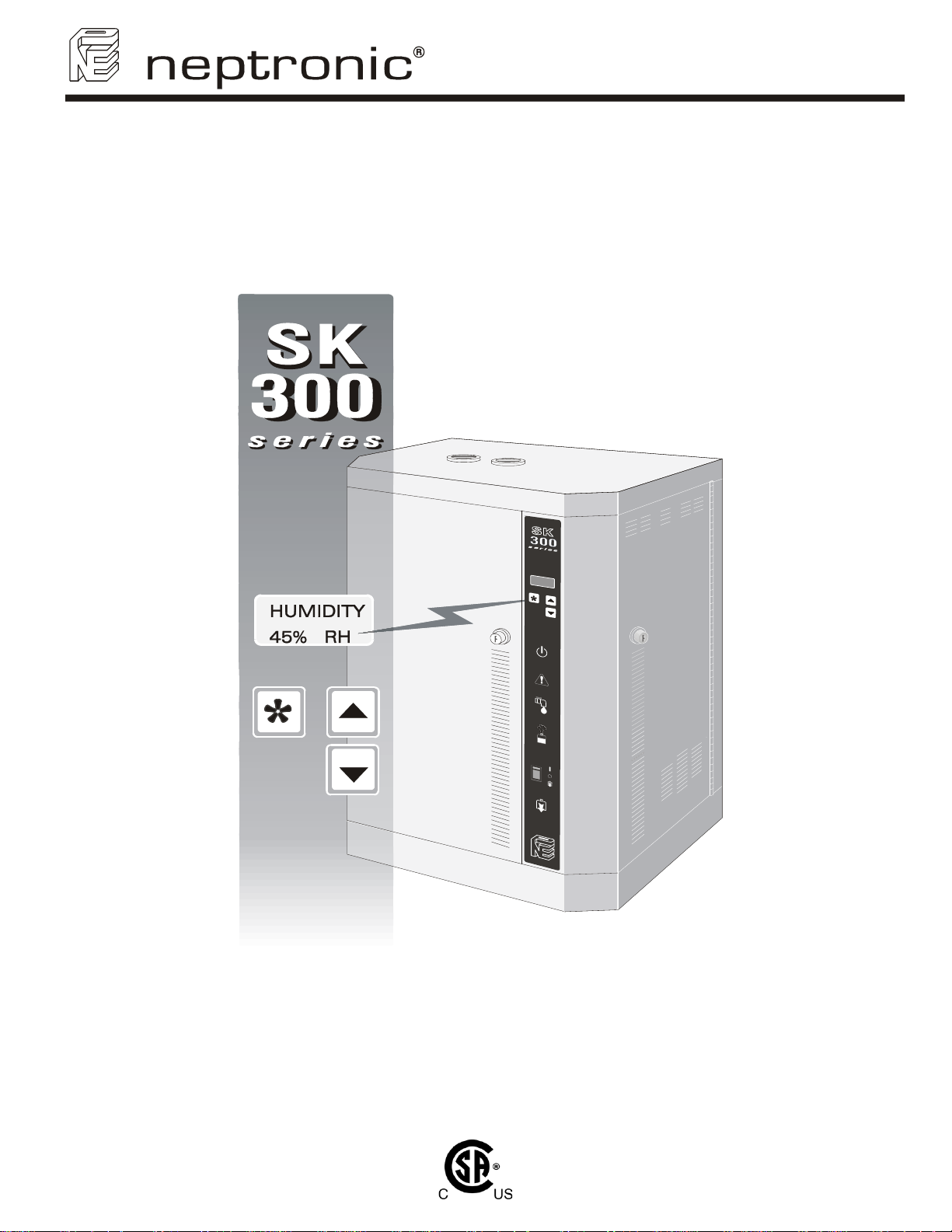
Steam Humidifier
SK300 series
SK300-ENG/071019
Installation instruction & user
manual
READ AND SAVE THESE INSTRUCTIONS
Page 2
SK300 Humidifier
Foreword
Foreword
1. These installation instructions and operation manual have been developed to facilitate the installation and the
operation of the SK300 series steam humidifier.
The strict application of these instructions will ensure the conformity of your installation and operation as per
manufacturer's recommendations.
2. The application of these instructions is one of the conditions for the application of the warranty.
3. The application of these instructions does not ensure at any time conformity to procedures, regulation or local
codes, regarding electric installation and connection to local water supply.
4. This product has been declared to conform to applicable Canadian and American safety standards and
directives and bear the CSA (c) & (us) mark. The certificate of conformity CSA is available upon request to the
manufacturer.
5. © 2007: All right reserved, this document cannot be reproduced totally or partially by any mean whether,
electronic, mechanical, photocopy, recording or other, without prior written authorization of National
Environmental Products Ltd.
Manufacturer Presentation
National Environmental Products Ltd. (NEP) is the owner of the brand Neptronic®.
NEP develops, manufactures and services a complete line of:
• Steam humidifiers,
• Humidistat among the most precise and the most reliable on the market,
• Actuators to regulate air damper or valves,
• Electric heaters,
• Thermostats and other control peripherals used to control HVAC equipment.
For more information about our products, visit our web site at www.neptronic.com
Each Neptronic
From the inspiration to realization, innovation has been the standard in design. As the result of this dedication, NEP Ltd.
owns several patents, notably the ENERDRIVE system and the AFEC system.
Manufacturing is conducted on the premises of our modern 80,000 sq.ft. (7 000m
Our quality system is built on the ISO 9001 model.
Our vision '' Customer for Life'' is realized by listening to their needs and by supplying them with products, which
exceed their expectations in quality, functionality and durability.
®
product benefits from over 25 years of experience of our qualified staff.
National Environmental Products Ltd.
Tel. (Toll free): 1 800 361-2308
Tel.: (1) (514) 333-1433
Fax: (1) (514) 333-3163
Fax Customer service: (514) 333-1091
Business hours: from Monday to Friday, 8:00am to 5:00pm (Eastern time)
2
) facility in Montreal, Canada.
i
Page 3

SK300 Humidifier
Table of contents
Table of contents
Foreword and Manufacturer Presentation.……………….…….……………………………………………………………….i
1. Presentation..............................................................................................................................................................2
1.1. Overview .................................................................................................................................................................................2
1.2. Definition .................................................................................................................................................................................3
2. Characteristics.........................................................................................................................................................4
2.1. Dimensions & weight...............................................................................................................................................................4
2.2. Output and power consumption...............................................................................................................................................5
3. Mechanical installation............................................................................................................................................6
3.1. General recommendations......................................................................................................................................................6
3.2. Positioning...............................................................................................................................................................................6
3.3. Wall mounting..........................................................................................................................................................................6
4. Steam dispersion system selection and positioning...........................................................................................7
4.1. Steam dispersion system selection.........................................................................................................................................7
4.2. Positionning of S.A.M or S.A.M.E2..........................................................................................................................................9
5. Steam output connection......................................................................................................................................12
5.1. Typical installation.................................................................................................................................................................12
5.2. General recommendations....................................................................................................................................................12
5.3. Installation of “S” traps on the steam line..............................................................................................................................12
5.4. Position of steam output........................................................................................................................................................ 13
5.5. Installation of humidifier with Space Distribution Unit (SDU).................................................................................................14
6. Plumbing connection.............................................................................................................................................15
6.1. Water supply .........................................................................................................................................................................15
6.2 Drain connection ...................................................................................................................................................................16
7. Power supply connections....................................................................................................................................16
8. Low voltage control connections.........................................................................................................................17
8.1. ''ON/OFF'' Humidifier.............................................................................................................................................................17
8.2. Modulating Humidifier............................................................................................................................................................17
8.3. Common Alarm Connections.................................................................................................................................................21
8.4. Controls Placement (steam dispersed into a duct or AHU)...................................................................................................21
9. Front panel display features.................................................................................................................................22
9.1. Description display modes.....................................................................................................................................................23
9.2. Programming.........................................................................................................................................................................25
10. Control p.c. board ..................................................................................................................................................26
10.1. Main p.c. board......................................................................................................................................................................26
10.2. Modulating p.c. board............................................................................................................................................................26
11. Start up procedure.................................................................................................................................................27
12. Service.....................................................................................................................................................................28
12.1. General .................................................................................................................................................................................28
12.2. Evaporation chamber cleaning..............................................................................................................................................28
13. Exploded view & Bill of Material...........................................................................................................................31
13.1. Exploded view.......................................................................................................................................................................31
13.2. Bill of material........................................................................................................................................................................32
14. Trouble shouting guide.........................................................................................................................................34
General condition of Sale & Warranty...……………………………………………………….……………………………….37
1
Page 4
1. Presentation
Thank you to have chosen one of the Neptronic
humidifier for its category.
1.1. Overview
1.1.1. List of accessories supplied
• 2 sets of keys.
• 2 adjustable collars for the connection of the steam hose for each steam output.
• 1 female fitting ¾ hydraulic for the drain output of the evaporation chamber.
• 1 female fitting ½ hydraulic for the drain output of the drip pan.
• 1 Installation instruction and operation manual.
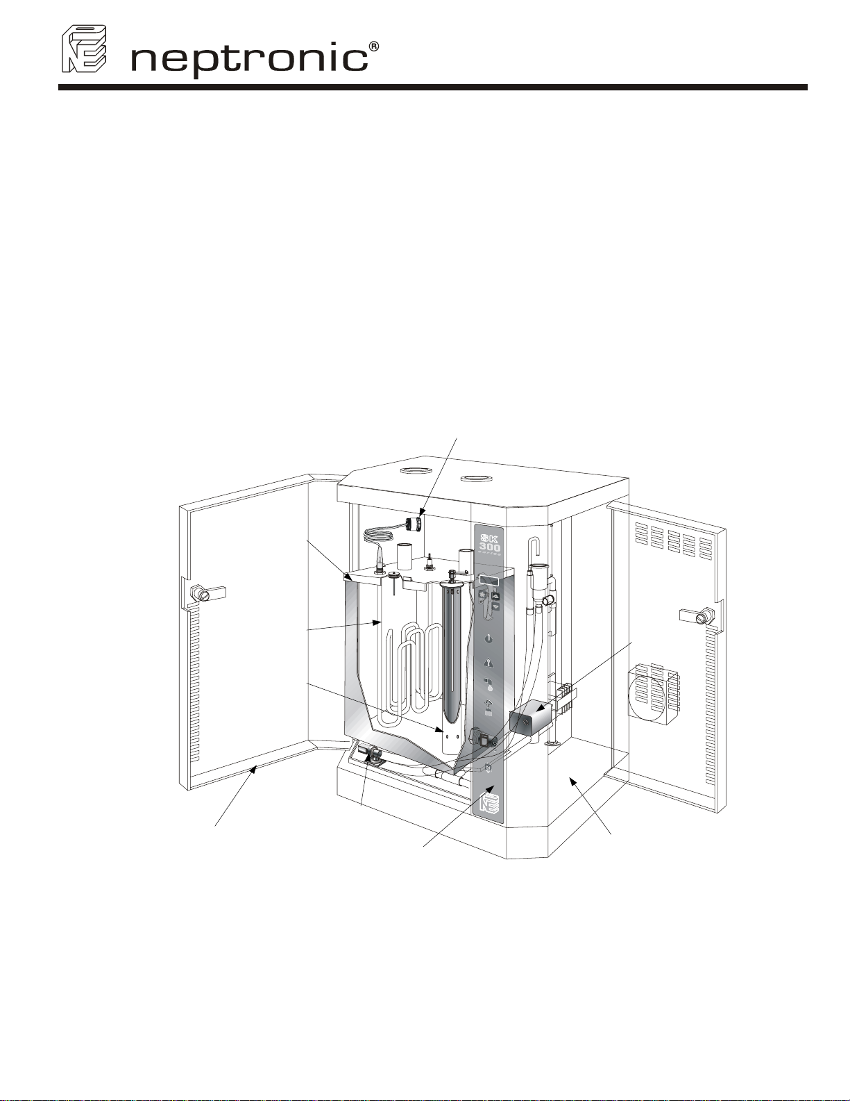
1.1.2. Overview of the Humidifier
SK300 Humidifier
User Manual
®
products. You have purchased the best and the most robust
Heater element
connector
Evaporation
chamber
Evaporation
chamber
Drain valve
Electrical
compartment
Access door to
mechanical
compartment
Heater element
Level sensor
chamber
Water supply valve
Control panel
(Illus. 1)
2
Page 5

SK300 Humidifier
User Manual
1.1.3. Options avalaible
The following options are available when purchasing a SK300 humidifier:
• Modulating control humidifier – suffix M (i.e. SK320M)
• Humidifier for system supplied with Deionised water or Reverse Osmosis water, dissolved solids
more than 1 ppm (SF DI-APPLICATION)
• Humidifier for system supplied with Deionised water or Reverse Osmosis water, dissolved solids
more than 0.028 ppm (SF ULTRAPURE-DI)
• Internal Drain Cooler (IDC) to temper the drain water to a temperature below 140°F (60°C) (SF
DRAINCOOL-INT)
• Space Distribution Unit mounted on humidifier (SDU) or remote installation (SDU-REM)
• Network communication system, BACnet – suffix B (i.e. SK320M-600-3B)
• Stainless steel humidifier cabinet – suffix P (i.e. SK320M-600-3P)
• Dry contact to activate an external fan relay on a call for humidity (SF SK300FANRELAY)
• Fill and drain trap assembly (see section 13. Exploded view item L) without copper elbows for
easy access cleaning – suffix N (i.e. SW TRAPSMA-N)
• Fill and drain trap assembly (see section 13. Exploded view item L) with check valve for high
static pressure inside the duct/AHU or multiple humidifiers using a single Multi-Steam – suffix C
(i.e. SW TRAPSMA-C)
• Fill and drain trap assembly (see section 13. Exploded view item L) with check valve and an
external actuated drain valve for hard water condition – suffix F (i.e. SW TRAPSMA-F)
1.2. Definition
1.2.1. Evaporation chamber
Assembly including the metal cylinder and a cover equipped with one or several heater elements. It is
the heart of the humidifier, which produce steam.
1.2.2. SDU (Space Distribution Unit)
Integrated steam distribution unit, optional on certain humidifiers.
1.2.3. Multi-Steam system
Custom made system of steam distribution. This system is designed to allow very short absorption
distances (less than 3 feet or 900mm).
1.2.4. S.A.M. (Steam Absorption Manifold)
Steam manifold adapted to air duct size to allow steam absorption in relatively short distance (less than
5 feet or 1500mm).
1.2.5. S.A.M.E2 (Steam Absorption Manifold with 2 Eyelets)
Steam manifold with two eyelets adapted to application with restricted air duct dimensions to allow
steam absorption in relatively short distance (less than 5 feet or 1500mm).
3
Page 6
2. Characteristics
SDU
Space Distribution
Unit (option)
Steam Humidifier
SK300 Humidifier
User Manual
D
A
E
Model
SK302
SK304
SK306
SK310
SK314
SK320
SK330
B
(Illus. 2)
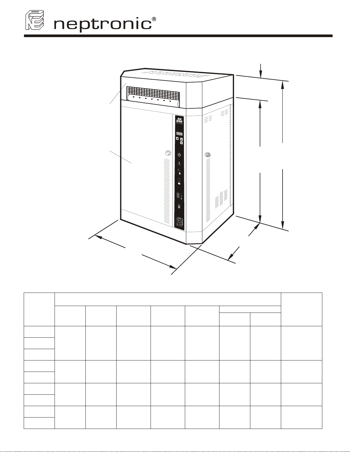
2.1. Dimensions & weight
Dimensions of the cabinet inch (mm)
A B C D E
23 ½
(597)
28 ½
(724)
28 ½
(724)
18 ½
(470)
21
(533)
21
(533)
11 ½
(292)
12 ½
(318)
12 ½
(318)
5 ⅝
(140)
6 ⅝
(165)
12 ⅞
(324)
29 ⅛
(737)
35 ⅛
(890)
41 ⅜
(1048)
C
Weight lb (kg)
Empty
44
(20)
66
(30)
66
(30)
Full of
water
57
(26)
115
(52)
115
(52)
Option SDU
Model
Weight
lb (kg)
SDU-1
20 (9)
SDU-2
25 (11)
SDU-3
45 (20)
SK340
SK360
4
31 ¼
(794)
32
(813)
12 ½
(318)
- -
110
(50)
205
(93)
-
Page 7
SK300 Humidifier
User Manual
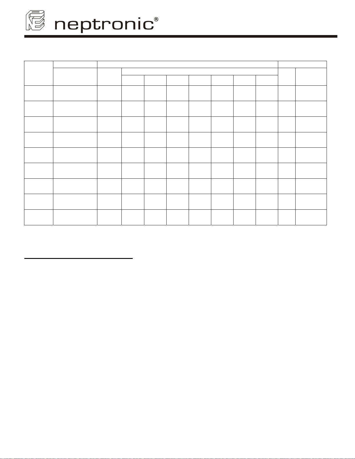
2.2. Output and power consumption
Steam Consumption
Model
SK302
SK304
SK306
SK310
SK314
SK320
SK330
SK340
SK360
Option:
• On modulating humidifier, the maximum steam output can be programmed with the function ''LOCK ON'' in
Program mode.
WARNING (MODULATING HUMIDIFIER)
ACCORDANCE WITH THE ABOVE TABLE, DO NOT TAKE ACCOUNT A POSSIBLE REDUCTION OF STEAM
OUTPUT, DUE TO MODULATION.
Capacity
lb/hr (kg/hr)
6
(2.7)
12
(5.5)
18
(8)
30
(14)
40
(19)
60
(28)
90
(41)
120
(56)
180
(82)
Power
(KW)
2 8.5 10
4 17 19 11.5
6 26 30 16.5 13 7.2 10.5 6 1
10 - - 28 - 12 - 10 1
13.5 - - 38 - 16.5 - 13.5 1
20 - - 57 - 25 - 20 2
30 - -
40 - - 120 - 50 - 40 2
60 - - - - 72 - 60 3
240/1
208/1
: MAXIMUM POWER OF THE ELECTRICAL INSTALLATION SHOULD BE IN
Amperage (A)
208/3 480/1 480/3 600/1 600/3
-
-
4.5 - 3.5 - 1
8.5 5 7 4 1
- 36 - 30 2
Steam Output
Qty
Diameter
inch (mm)
1 ⅜
(35)
1 ⅜
(35)
1 ⅜
(35)
1 ⅜
(35)
1 ⅜
(35)
1 ⅜
(35)
1 ⅜
(35)
2 ⅛
(54)
2 ⅛
(54)
5
Page 8
SK300 Humidifier
User Manual
3. Mechanical installation
3.1. General recommendations
• CAUTION: RISK OF ELECTRIC SHOCK. DISCONNECT THE APPLIANCE FROM THE ELECTRIC SUPPLY
BEFORE TO PROCEED TO INSTALLATION.
• Location: Plan a location easy to access in order to permit an easy inspection and servicing of the humidifier.
Do not install humidifier where failure of the appliance could cause damage to the building structure or to costly
equipment.
This location should be well ventilated; the ambient temperature should not exceed 85°F (30°C).
• The maximum distance between the humidifier and the ventilation duct should not exceed 16 feet (5 meters)
(maximum length of the steam hose).
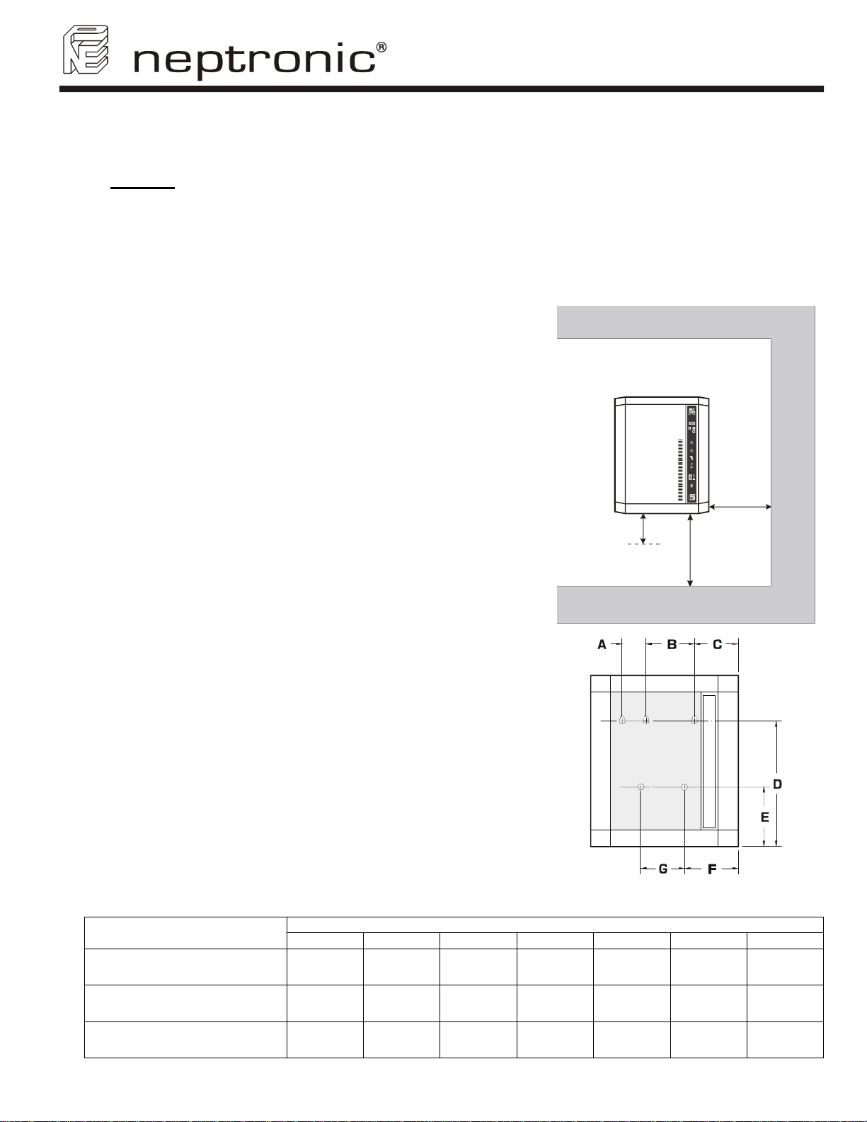
3.2. Positioning
• The front panel and the right side (electrical compartment) should be
accessible in order to permit the servicing.
Leave a clearance of at least 48” (1,25m) to the front panel and 24”
(0,6m) to the right side.
• The humidifier should be mounted at a minimum of 39” (1m) to 48”
(1,2m) above floor level.
Leave a clearance of at least 10” (0,25m) under the humidifier for
installation of water supply, drain piping and electrical connections.
3.3. Wall mounting
• Use the keyholes located on the back panel of the humidifier.
• Before to proceed to the wall mounting, take off the Evaporation
chamber sub assembly (see section 12, Servicing).
• Check the solidity of the chosen support or wall (bricks, concrete,
stud partition wall, etc) on which the humidifier will be mounted.
• Drill holes for the upper anchors (holes with eyelet) into the support
or wall as per dimensions specified in the table (illus.4).
The holes dimensions (diameter and depth) should by in accordance
with the recommendations of the chosen anchors.
• Install then bolt anchors, if required.
• Screw-on the 2 or 3 upper screws (holes with eyelet) of a minimum
diameter of #10 (6mm) (screws are not supplied).
Leave a clearance between head screws and wall in order to permit
the mounting of the humidifier.
• Use the keyholes located on the back panel of the humidifier.
• Hang on the humidifier to the 2 or 3 screws; it is preferable let the
front door open during this operation.
According to the size and weight of the humidifier, you may need the
help of a second person to assist you.
• When the humidifier is positioned on the upper screws, tighten the
screws to secure the humidifier.
• If applicable, install and secure lower screws.
Model
A B C D E F G
Dimensions inches (mm)
10'’
(0,25 m)
Positioning (Illus. 3)
Front view (Illus. 4)
24'’
(0,60 m)
39 to 48'’
(1 to 1,2 m)
SK302, SK304, SK306
SK310, SK314,
SK320, SK330
SK340, SK360
6
- 8 (202) 5
- 10 (254) 8 (203) 24 ⅝ (625) 11 (276) 8 (203) 10 (254)
4 (100) 12 (303) 10 ½ (265) 27 ½ (698) 11 (276) 18 ⅜ (468) -
3/16 (165) 19 ¾ (516) - - -
Page 9
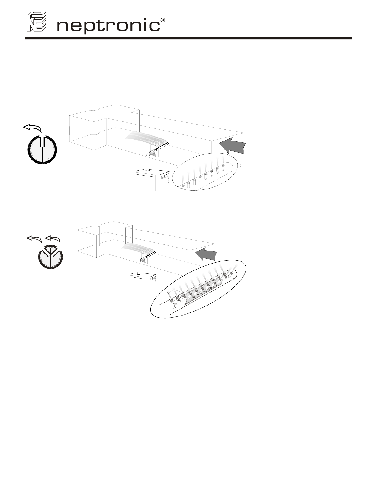
4. Steam dispersion system selection and positioning
4.1. Steam dispersion system selection
In order to prevent the accumulation of condensation in air ducts, NEP has designed 4 basic configurations of
steam distribution to provide the client with the most economical solution for any particular application.
4.1.1. S.A.M. (steam absorption manifold) Horizontal duct
SK300 Humidifier
User Manual
The SAM is to be installed where
absorption distances are short, less
than 5 feet (1500mm), and/or low
duct temperatures are in effect.
(Illus. 5)
a
i
r
4.1.2. S.A.M.E2 (steam absorption manifold) Horizontal duct
a
i
r
0
90
(Illus. 6)
The SAME2 is to be installed
where absorption distances are
short, less than 5 feet (1500mm)
and/or low duct temperatures are
in effect. SAME2 are used in
applications with restricted duct
dimensions.
7
Page 10
SK300 Humidifier
User Manual
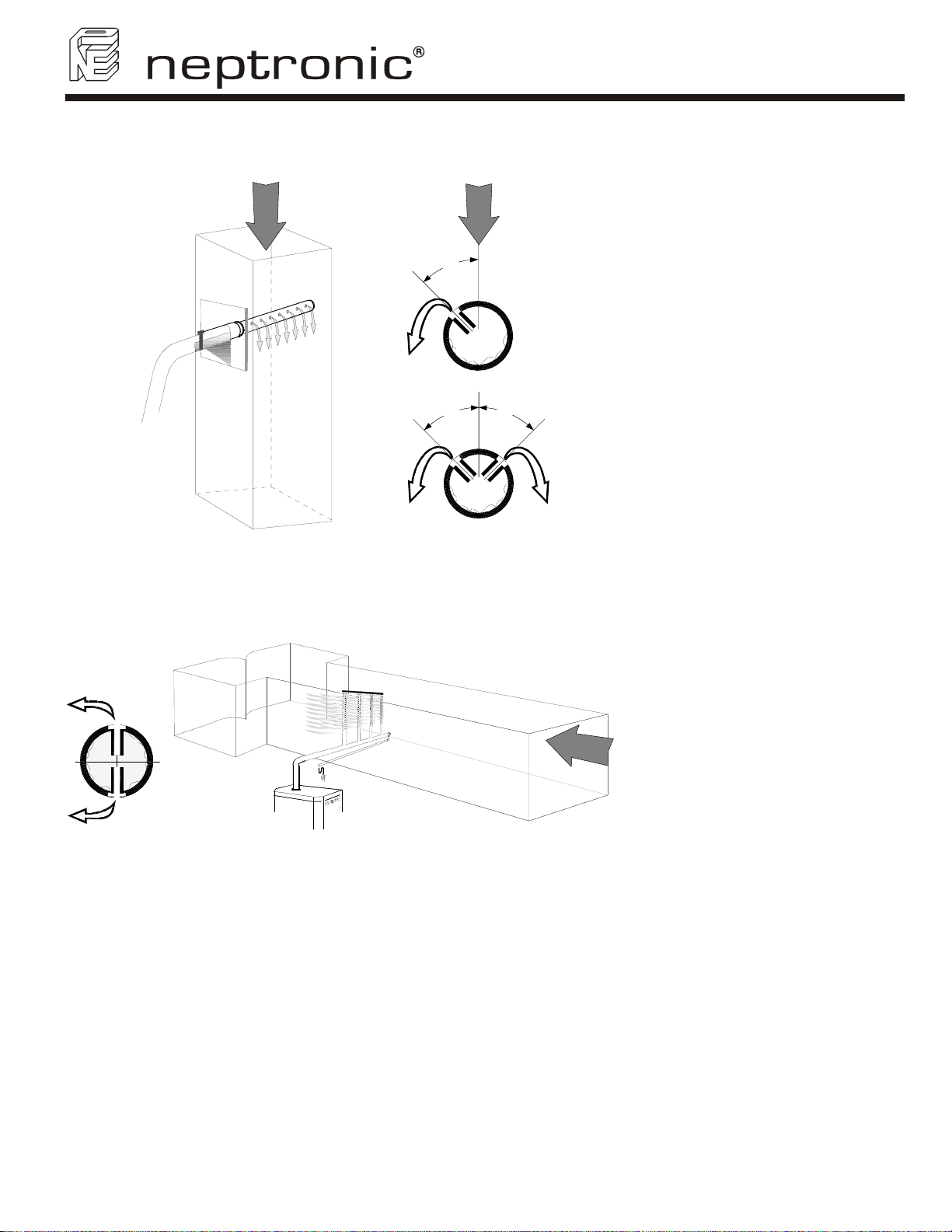
4.1.3. S.A.M. or S.A.M.E2 (steam absorption manifold) Vertical duct
r
i
a
S.A.M.
S.A.M.E2.
45°
45°
air
45°
SAM or SAME2 for vertical ducts
are used where the absorption
distances are normal and the
client requires an economical as
well as an efficient solution.
(Illus. 7)
4.1.4. Multi-Steam system
(Illus.8)
The Multi-Steam system is to be
installed in critical locations in air
handling systems, particularly
where absorption distances are
very short, less than 3 feet
(900mm), or low air duct
temperatures are in effect.
a
i
r
The Multi-Steam is custom made
to the dimensions of duct or AHU.
Instructions to install Multi-Steam
system are described in a specific
installation instructions manual
enclosed with the Multi-Steam
system.
8
Page 11
SK300 Humidifier
User Manual
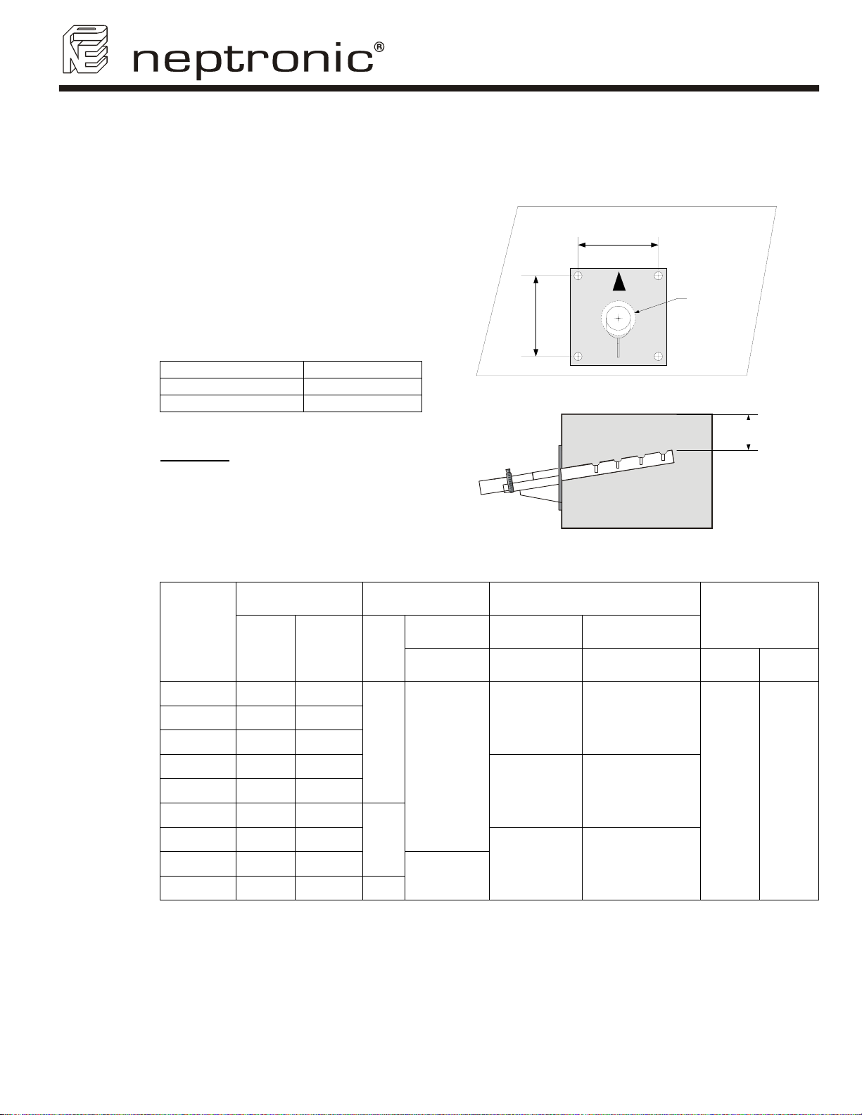
4.2. Positionning of S.A.M or S.A.M.E2
4.2.1. Duct mounting
Steam manifold should be mounted and
secured through the side of the air
handling unit or duct. Provision should be
made for safe accessibility, ideally with an
observation light and window.
Check that the construction of the duct
wall is suitable enough to support the
steam pipe for the duration of the
installation life.
Dimension of hole size in the duct must be
as per table below:
Steam manifold Ø Hole size ØA
1 ⅜’’ (35mm) 2’’ (51mm)
2 ⅛’’ (51mm) 3’’ (78mm)
WARNING: Risk of condensing. Ensure
that the minimum distance of the end of
the manifold is at least 4’’ (102mm) from
the top of the duct.
5'’
(120mm)
Minimum distance (Illus. 10)
5'’
(120mm)
(Illus. 9)
ØA
4'’ minimum
(102mm)
4.2.2. Recommendations for SAM distribution pipes
Maximum
Capacity
Model
(lb/hr) (kg/hr) Qty
SK302
SK304
SK306
SK310
SK314
SK320
SK330
SK340
SK360
6 2.7
12 5.5
18 8
30 14
40 19
60 28
90 41
120 56
180 82 3
Note: For higher static pressure, please contact the manufacturer.
Outlet Distribution pipes
Diameter
In
(mm)
Minimum
length
in.
(mm)
12
(300)
1
1 ⅜
(35)
24
(600)
2
32
2 ⅛
(750)
(51)
Maximum
length
in.
(mm)
24
(600)
48
(1200)
64
(1500)
Maximum
static pressure
in. of
water
(Pa)
5 1245
9
Page 12
H
10'’ minimum
(250mm)
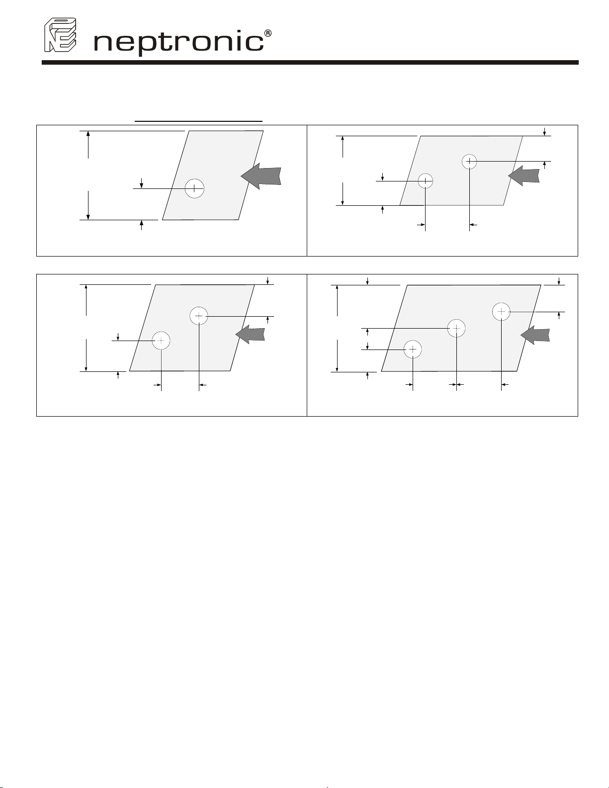
4.2.3. Placement of steam pipe in horizontal duct
1 ⅜’’ (35mm) diameter pipe
H
10'’ minimum
air
1/3 H
1 pipe (Illus. 11)
2 ⅛’’ (51mm) diameter pipe
(250mm)
3'’ minimum
(80mm)
SK300 Humidifier
User Manual
8'’
(200mm)
2 pipes (Illus. 12)
6'’ minimum
air
(150mm)
H
24'’ minimum
(600mm)
1/5 H
8'’
(200mm)
2 pipes (Illus. 13)
air
2/5 H
36'’ minimum
(900mm)
1/2 H
H
air
1/6 H
10'’
(250mm)
3 pipes (Illus. 14)
10'’
(250mm)
Note: 2 ⅛’’ (51mm) steam pipe must be supported on the end by appropriate duct hanger or
strap (supplied by others).
1/3 H
10
Page 13
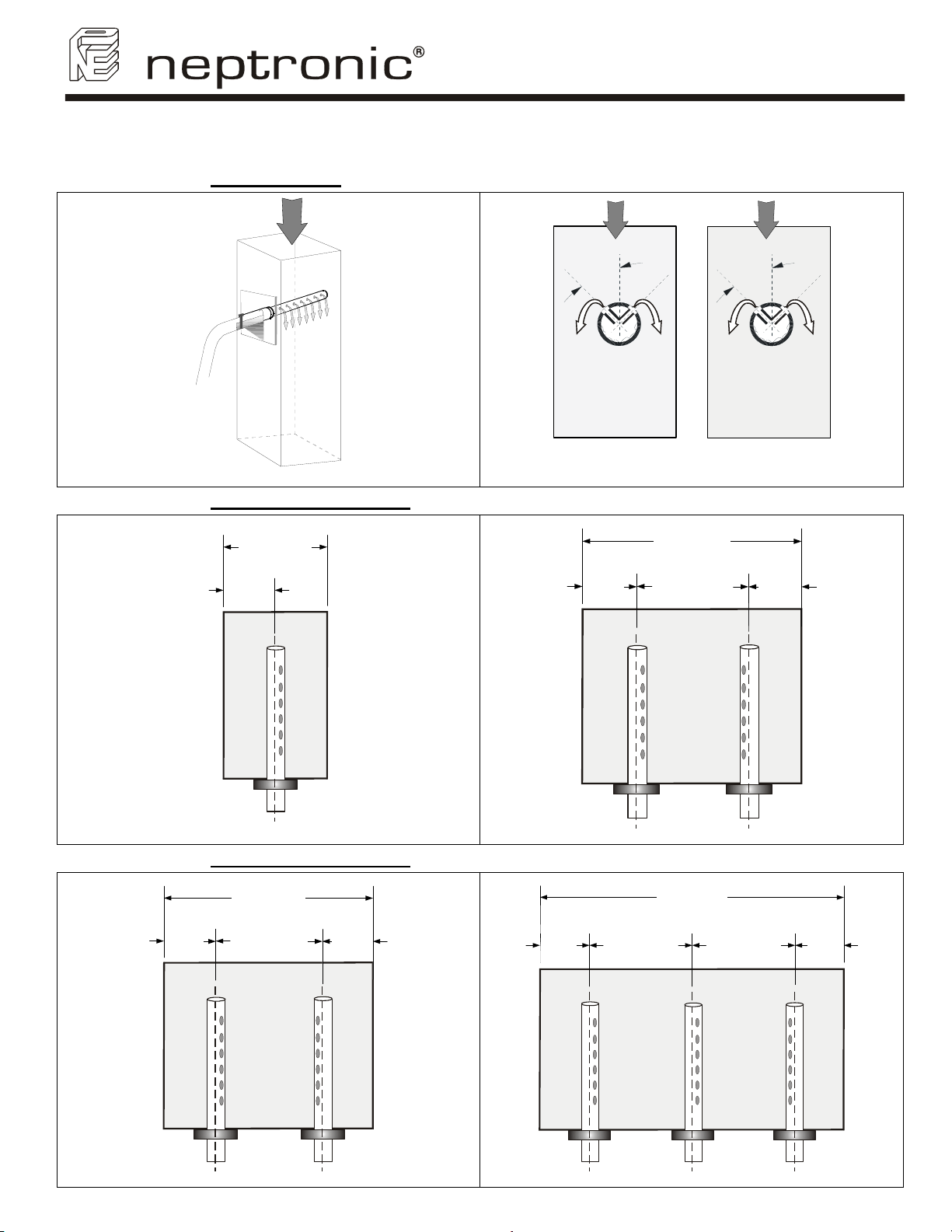
4.2.4. Placement of steam pipe in vertical duct
Eyelet orientation
SK300 Humidifier
User Manual
air
3D view (Illus. 15)
1 ⅜’’ (35mm) diameter pipe
W
10’’ minimum
(250mm)
1/2 W
air
45°
air
45°
S.A.M S.A.M.E2
(Illus. 16)
W
24’’ minimum
(600mm)
1/2 W
1/4 W1/4 W
1 pipe (Illus. 17)
2 pipes (Illus. 18)
2 ⅛’’ (51mm) diameter pipe
W
24’’ minimum
(600mm)
1/2 W
2 pipes (Illus. 19)
11
1/4 W1/4 W
1/6 W 1/6 W
1/3 W 1/3 W
W
36’’ minimum
(900mm)
3 pipes (Illus. 20)
Page 14
5. Steam output connection
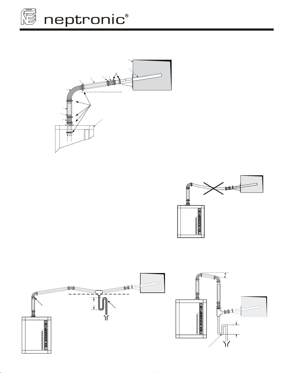
5.1. Typical installation
2
1
4
3
SK300 Humidifier
User Manual
6
5
1
2
4
3
2
1
15 %
Humidifier
Clamps
1
Flexible hose
2
Rigid copper pipe
3
Insulation
4
Steam distribution manifold
5
Duct
6
(Illus. 21)
5.2. General recommendations
Please follow these general rules of installation in order to avoid any static pressure inside distribution pipes
and into the humidifier evaporation chamber, and also to avoid any condensation accumulation.
a) The slope of the steam hose (rigid or flexible)
should not be less than 15% (7 horizontal length for
1 vertical length) in order to ensure continuous
drainage of condensation back to humidifier or to
steam trap.
b) Total length of the steam hose or rigid pipe should
not exceed 16feet (5 meters). Longer runs will result
in added condensation losses. Whenever possible,
use insulated copper piping. Flexible steam hose
should be used for short runs (up to 16ft or 5m) or for
interconnecting between the rigid pipe runs.
c) Whenever using rigid copper, these ones should
be insulated to diminish condensation build up.
Incorrect installation
(Illus. 22)
5.3. Installation of “S” traps on the steam line
The lowest point of any steam hose or rigid pipe must be the humidifier. If necessary a steam separator
(S trap) should be installed higher than the static pressure of the system by at least 2” (51mm).
15% 15%
Steam outlet
12
8"
(Illus. 23)
Use "S" separator
when ceiling space is
limited and you need
to create 15% slopes
Use ‘’S’’ separator when
the steam distributor is
lower than the humidifier
steam outlet
(Illus. 24)
15%
(203mm)
8'’
Page 15
Model
Small
Cabinet
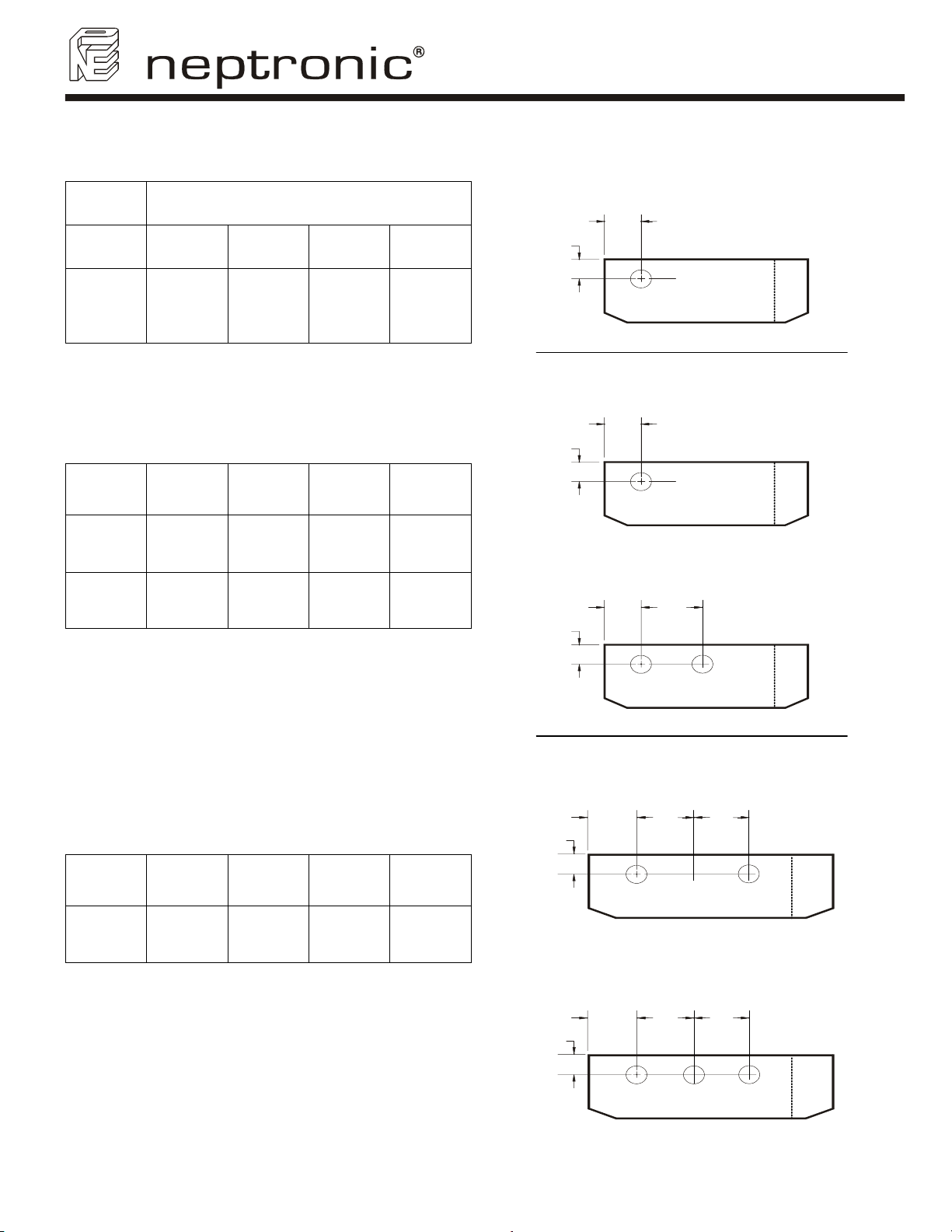
5.4. Position of steam output
Dimensions inches (mm)
I J
SK300 Humidifier
User Manual
Small Cabinet
(SK302-304-306)
I
J
SK302
SK304
SK306
Medium
Cabinet
SK310
SK314
SK320
SK330
5/16
4
(110)
K L M
-
5
9/32
(134)
4 13/16
(122)
4
(102)
4
(102)
5
5/8
(143)
5 5/8
(143)
M
M
Medium Cabinet
(SK310-314)
L
Medium Cabinet
(SK320-330)
K
L
Large Cabinet
(SK340)
P
Q
Large
Cabinet
SK340
SK360
13
N O P Q
7
(179)
7
(179)
5
3/16
(132)
5 11/16
(144)
P
Q
ON
Large Cabinet
(SK360)
ON
(Illus. 25)
Page 16
SK300 Humidifier
User Manual
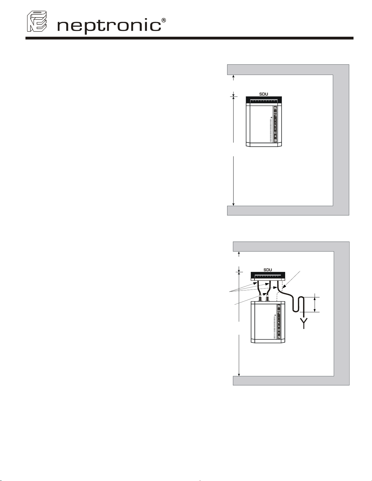
5.5. Installation of humidifier with Space Distribution Unit (SDU)
• The SDU should be installed in an
environment where the air is relatively
clean. This will avoid the blower from
getting clough with dust.
Without
additional
ventilation
54'’ (1,35 m)
18'’
(0,45 m)
• The humidifier should be mounted such
that the SDU fan section is at least 78”
(2m) above the floor.
• A minimum clearance of 18” (0.45m) from
the ceiling should be allocated to avoid
ceiling and wall condensation.
If additional ventilation is not present, the
fan should have a clearance from the
78'’
(2 m)
ceiling of at least 54” (1.35m). Proper
ventilation must be observed to avoid
ceiling and wall condensation.
SDU remote installation:
• The SDU can be in a different location
from the humidifier (remote SDU). Please
follow the piping recommendations
(section 5.2).
• Mount the SDU to the wall on brackets
SDU mounted on humidifier (Illus. 26)
(not supplied), do not drill mounting holes
thru the cabinet of the SDU.
• Connect the steam hose(s) to the bottom
inlet(s) of the SDU to the top of the steam
outlet(s) of the humidifier. Secure the
hose(s) with the supplied hose clamp.
• Connect the condensate hose to the
bottom of the SDU to an open drain.
• Connect the electrical wires from the SDU
to the top of the humidifier. Field wiring
must conform to local codes.
for SDU2 or SDU3
Without
additional
ventilation
54'’ (1,35 m)
Field piping
(not supplied)
2nd pipe
18'’
(0,45 m)
Field wiring
(by others)
4'’
(0.10m)
The fan of the SDU will operate for a period of
four minutes after steam production has
stopped to prevent condensation.
78'’
(2 m)
Avoid any obstruction of the ventilation
openings on top of the SDU.
Maintenance of the SDU:
• Clean the blower if there is an
accumulation of dust.
SDU remote installation (Illus. 27)
14
Page 17
SK300 Humidifier
User Manual
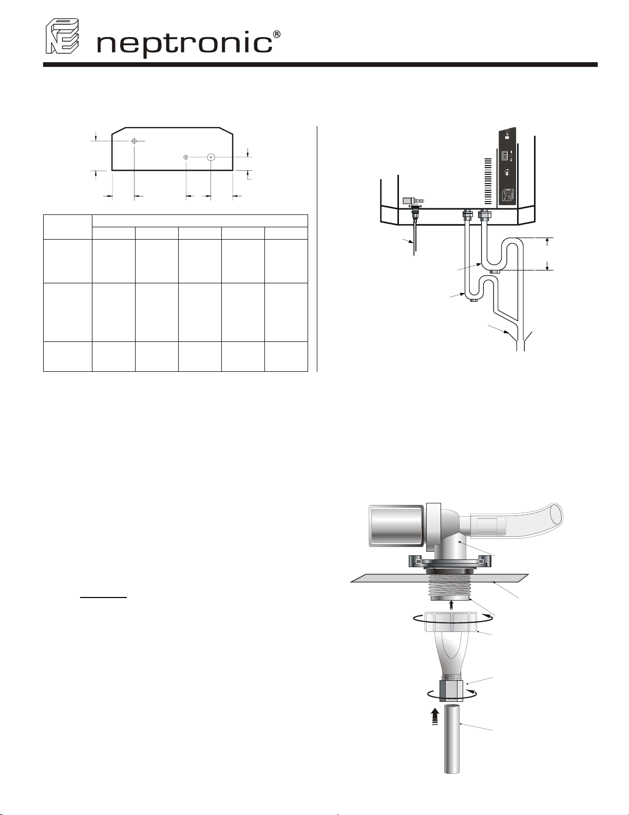
6. Plumbing connection
The operation of SK300 series humidifier is independent of variable water conditions, with soft or hard water. Therefore,
for normal operation, no pre-treatment of water is necessary.
C
B
9 ⅛
(232)
9 ¾
(248)
A
4 ⅛
(105)
4 ⅛
(105)
1 ¾
(44)
1 ¾
(44)
Water line
3/8'' hydraulic pipe
Evaporation chamber drain
3/4'' hydraulic pipe
Pan drain
1/2'' hydraulic pipe
Open drain ''P'' Trap
Model
SK302
SK304
SK306
SK310
SK314
SK320
DE
Bottom view (Illus. 28)
Dimensions inches (mm)
A B C D E
6 ½
(165) 2 (51)
7 ¼
(184)
1 ¾
(44)
SK330
SK340
SK360
7
(179)
1 ¾
(44)
9 ¾
(248)
4 ⅛
(105)
1 ¾
(44)
(Illus. 29)
6.1. Water supply
• Water inlet specifications:
9 Inlet water pressure: 10 to 70 psig (0,7 to 4,8 bars)
9 Maximum temperature: 85°F (30°C) maximum
9 3/8'' standard copper water line connection
• A shut off valve (not supplied) should be installed in the water supply line to the humidifier, close to the
humidifier to facilitate servicing.
• It is recommended to install a standard water strainer in the water supply line.
Please follow the steps described below:
• Connect 3/8'' copper pipe to the bottom 3/8''
compression fitting (supplied).
• Finger tighten the swivel top 3/8'' fitting to the male
threaded part of the valve.
CAUTION
: RISK OF DAMAGE TO THE VALVE.
DO NOT USE WRENCH TO TIGHEN SWIVEL.
Fill valve
(Intern)
Male threaded part of
the valve
Swivel top
10'’ minimum
(254 mm)
Base plate of
humidifier
Compression
fitting
Water line 3/8'’ (10mm) pipe
(by others)
(Illus. 30)
15
Page 18
SK300 Humidifier
User Manual
6.2. Drain connection
• Drain connection specification:
9 Evaporation chamber water drain temperature: 180°F (83°C).
9 Standard hydraulic fitting: 1 connector ¾ (evaporation chamber drain) and 1 connector ½ (Pan drain).
• 2 hydraulic threaded fitting located under the humidifier (see Illus. 29) must be connected to the drain pipe. We
recommend the use of standard copper hydraulic pipes ¾ and ½.
• Ensure that the drain pipe dimension is sufficient, especially if more than one humidifier is evacuating into the
same drain line.
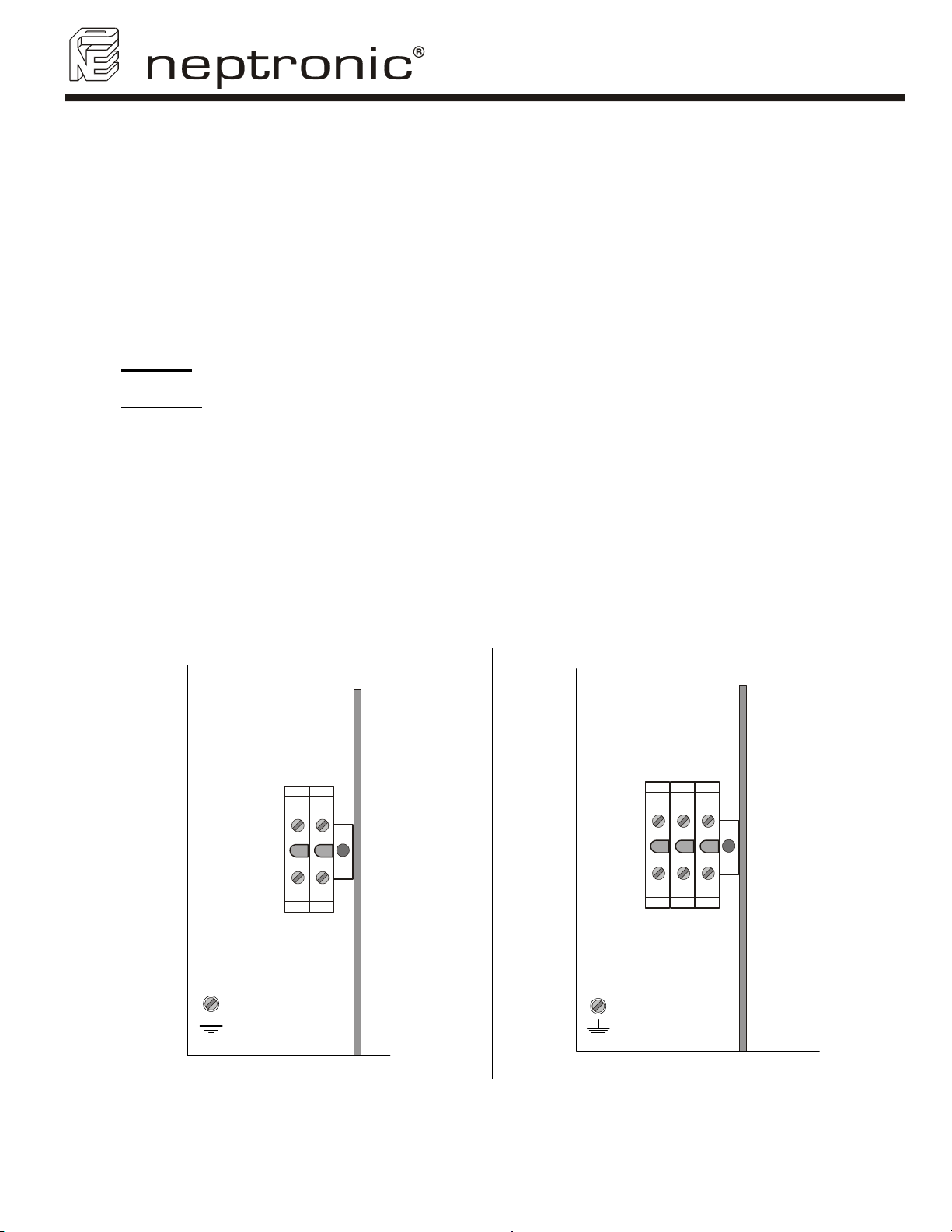
7. Power supply connections
• CAUTION
BEFORE TO PROCEED TO THE CONNECTION.
• WARNING:
voltage terminal block designated 1, 2 and 3.
• The wiring to the Humidifier should be done by a qualified electrician, and conforming to the procedure,
regulation and local codes.
• Use only coppers conductors.
• An external over current protection and disconnect circuit breaker should be installed on the supply adjacent to
the humidifier.
• A knock out (not supply) should be installed at the bottom of the electrical compartment of the humidifier for
strain relief of the supply cable.
• Ensure that the size of the wire conductors is appropriate for the current supplied.
• Ensure that each terminal connection is properly secured.
• The ground conductor should be equipped with ring terminal and should be connected directly to the electrical
panel on the indicated location.
: RISK OF ELECTRIC CHOC. DISCONNECT THE HUMIDIFIER FROM THE ELECTRIC SUPPLY
RISK OF FIRE. Do not interchange the power terminal block designated L1, L2 and L3 with Low
1 Phase Connection
3 Phases Connection
PHASE 1
PHASE 2
PHASE 1
PHASE 2
L1 L2
GND
(Illus. 31)
16
L1 L2 L3
GND
PHASE 3
(Illus. 32)
Page 19
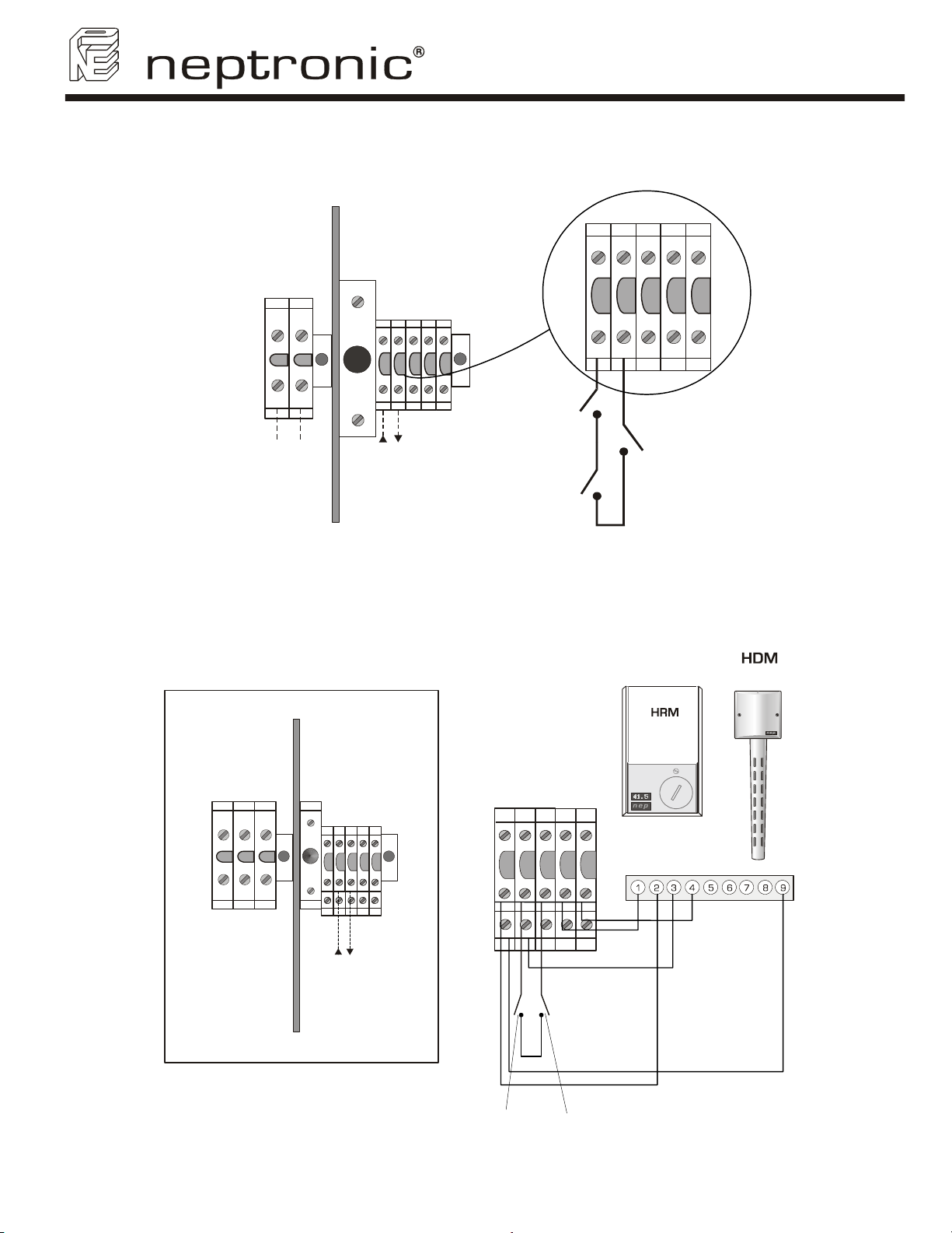
8. Low voltage control connections
8.1. ''ON/OFF'' Humidifier
SK300 Humidifier
User Manual
12789
Humidistat
5 Vdc
High voltage power
terminal block
Low voltage control
terminal block
(Illus. 33)
8.2. Modulating Humidifier
8.2.1. Humidity control by humidistat (external mode)
Connection to HDM or HRM humidistat.
High
limit
1
7
2
9
8
5 Vdc
Pressure
Differential
switch
L1 L2 L3
High voltage power
terminal block
F
5
Low voltage control
terminal block
67
5 Vdc
4321
98
High limit humidistat
(Illus. 34)
1
69
432F
875
Pressure Differential
switch
humidistat
or
com
24 VAC
%RH
MOD
Set point
17
Page 20
SK300 Humidifier
User Manual
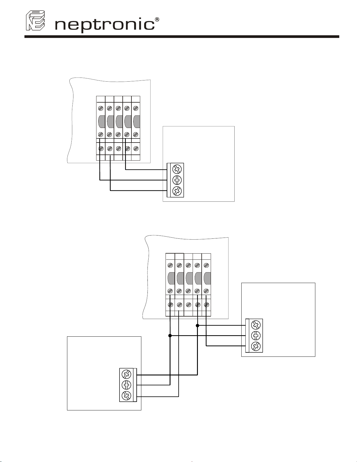
8.2.2. Humidity control by humidifier (internal mode)
Humidity controlled by humidifier, using HRM-X or HDM-X as space sensor.
SK300
1
432F
HRM-X
or
HDM-X
69
VAV system with humidity controlled by humidifier, using HDM-X as Hi limit duct sensor and HRM-X or
HDM-X as space sensor.
875
To Term. #3
To Term. #F
To Term. #6
(Illus. 35)
1
COMMON
2
24 VAC OR VDC
3
0-10 VDC OUTPUT
SK300
1
432F
HDM-X
69
HRM-X
875
To Term. #3
To Term. #F
To Term. #4
1
COMMON
2
24 VAC OR VDC
3
0-10 VDC OUTPUT
or
HDM-X
Note: when HDM-X is used as Hi limit
Duct sensor, control signal jumper
should be placed on 0-10 Vdc on
Modulating PCB (see section 8.2.4 of
COMMON
24 VAC OR VDC
0-10 VDC OUTPUT
1
2
3
To Term. #3
To Term. #F
To Term. #6
installation instructions)
(Illus. 36)
18
Page 21
SK300 Humidifier
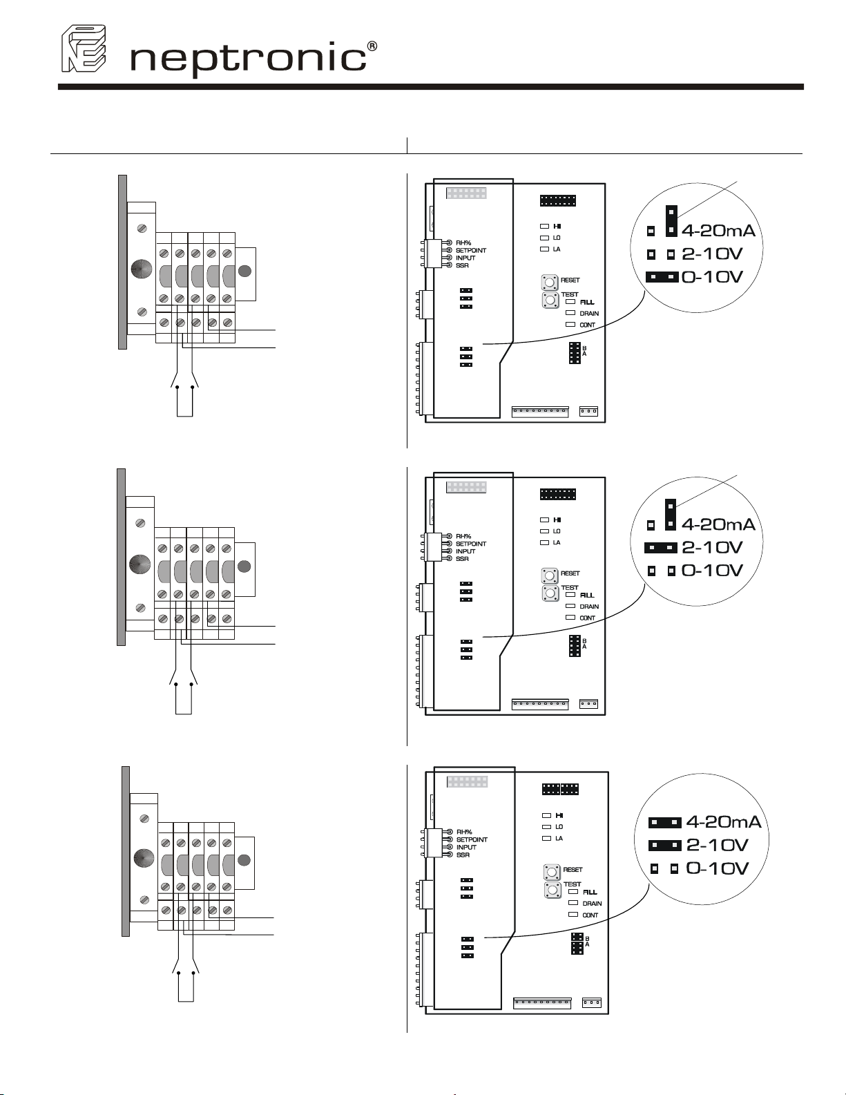
8.2.3. Humidity Signals (internal mode)
Terminal Block Modulating Printed Circuit Board
Humidity signal 0-10 Vdc
PCB970819
REV. C
User Manual
Extra jumper
High limit
Humidistat
High limit
Humidistat
1
69
432F
875
Pressure Differential
Switch
5 Vdc
(Illus. 37)
1
69
432F
875
Pressure Differential
Switch
5 Vdc
(Illus. 38)
-
0-10 Vcc
+
-
2-10 Vcc
+
CONTROL
INPUT
4-20mA
0-10V
2-10V
HUMIDITY
INPUT
4-20mA
2-10V
0-10V
TOP PCB
MODULATING
Humidity signal 2-10 Vdc
CONTROL
INPUT
4-20mA
0-10V
2-10V
HUMIDITY
INPUT
4-20mA
2-10V
0-10V
TOP PCB
MODULATING
Humidity signal 4-20 mA
(Illus. 40)
PCB970819
REV. C
(Illus. 41)
PCB970819
REV. C
Jumper on
0-10V
Extra jumper
Jumper on
2-10V
1
69
High limit
Humidistat
5 Vdc
432F
875
-
+
Pressure Differential
Switch
(Illus. 39)
4-20 mA
CONTROL
INPUT
4-20mA
0-10V
2-10V
Jumpers on
HUMIDITY
INPUT
4-20mA
2-10V
0-10V
TOP PCB
MODULATING
(Illus. 42)
4-20mA & 2-10V
19
Page 22
SK300 Humidifier
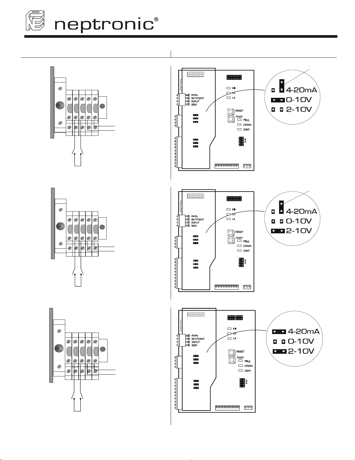
8.2.4. Control Signals
Terminal Block Modulating Printed Circuit Board
Control signal 0-10 Vdc
PCB970819
REV. C
User Manual
Extra jumper
High limit
Humidistat
High limit
Humidistat
1
69
432F
875
Pressure Differential
Switch
5 Vdc
(Illus. 43)
1
69
432F
875
Pressure Differential
Switch
5 Vdc
(Illus. 44)
+
0-10 Vcc
-
+
2-10 Vcc
-
CONTROL
INPUT
4-20mA
0-10V
2-10V
HUMIDITY
INPUT
4-20mA
2-10V
0-10V
TOP PCB
MODULATING
Control signal 2-10 Vdc
CONTROL
INPUT
4-20mA
0-10V
2-10V
HUMIDITY
INPUT
4-20mA
2-10V
0-10V
TOP PCB
MODULATING
Control signal 4-20 mA
(Illus. 46)
PCB970819
REV. C
(Illus. 47)
PCB970819
REV. C
Jumper on
0-10V
Extra jumper
Jumper on
2-10V
1
69
High limit
Humidistat
5 Vdc
432F
+
875
-
Pressure Differential
Switch
(Illus. 45)
4-20 mA
CONTROL
INPUT
4-20mA
0-10V
2-10V
Jumpers on
HUMIDITY
INPUT
4-20mA
2-10V
0-10V
TOP PCB
MODULATING
(Illus. 48)
4-20mA & 2-10V
20
Page 23
SK300 Humidifier
User Manual
8.3. Common Alarm Connections
A volt free contact is provided in the form of both a normally open and normally closed contact that will switch in
the event of an alarm on the SK300 humidifier.
1
• Wherever possible it is recommended to use
the normally closed contact. This contact will
open in the event of a humidifier fault.
• These contacts should be used to switch a
low voltage, ideally 24V, with a switching
current of no more than 3 Amps.
69
432F
875
Common
Normally Open
Normally Closed
(Illus. 49)
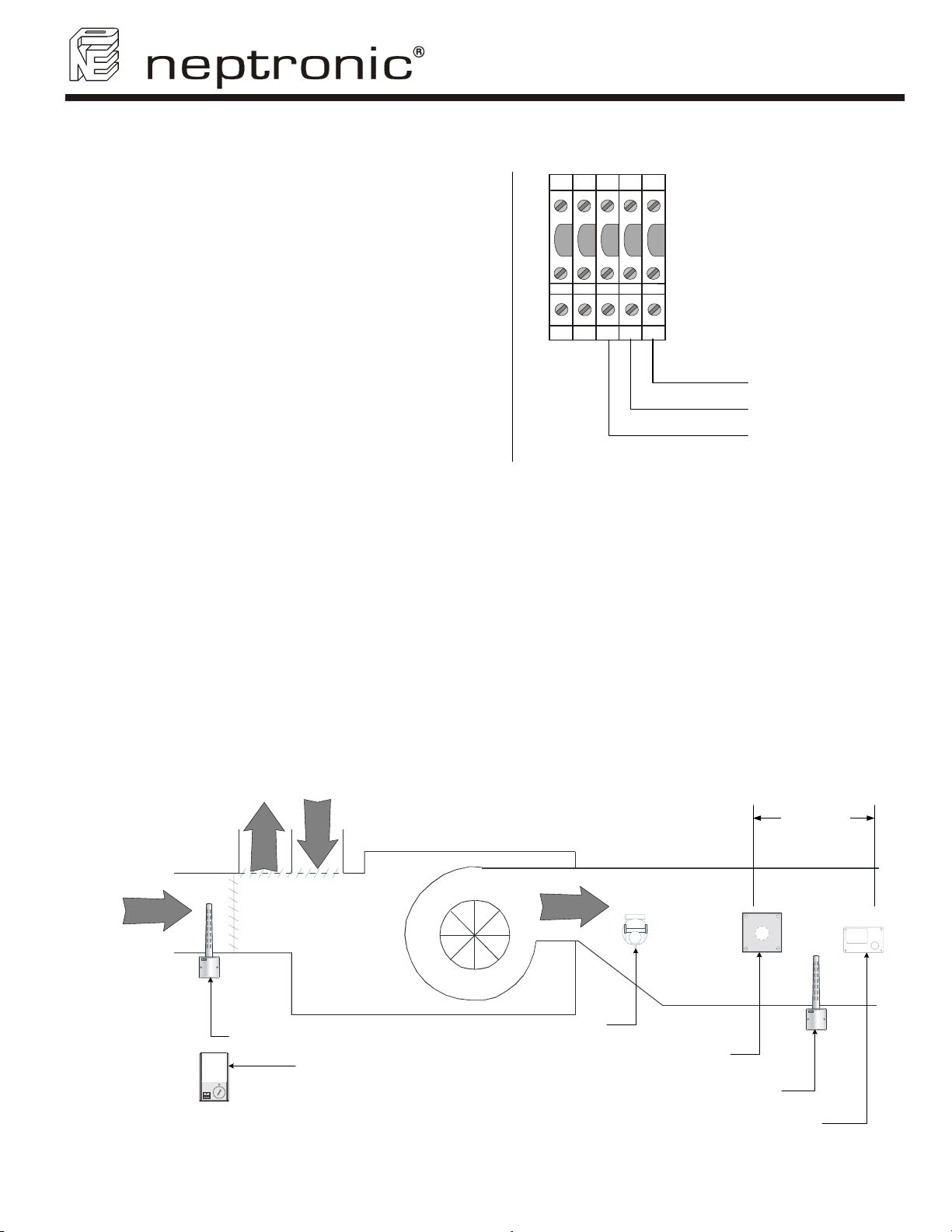
8.4. Controls Placement (steam dispersed into a duct or AHU)
Typical humidifier control system should include along with the humidifier:
• A wall or return duct humidistat
• A high limit duct humidistat,
• An air proving switch.
Placement of these devices is critical to proper operation of the overall system.
• The return duct humidistat must always be located before any outside air intake, in order to ensure
accurate sensing of the air from the humidified space.
• Alternatively a room humidistat can be used. The room humidistat should be located on an inside wall or
column. It should not be be near any discharge air from supply ducts or sources of heat or cold.
• The airflow switch must be positioned to accurately open on a loss of air flow, to prevent the humidifier
from running when there is no air to absorb humidity.
• The high limit humidistat must be positioned far enough - 6’ minimum (1.8m) - downstream of the steam
dispersion manifold(s) to prevent it from getting wet, but still allows it to accurately prevent
overhumidification of the duct that could result in condensation.
6' minimum
(1.8m)
a
r
i
a
r
i
r
i
a
a
r
i
Return HDM
humidistat
Or room HRM
humidistat
21
Air flow switch
(Illus. 50)
Steam dispersion
manifold
High limit HDM for
VAV application only
High limit humidistat
Page 24
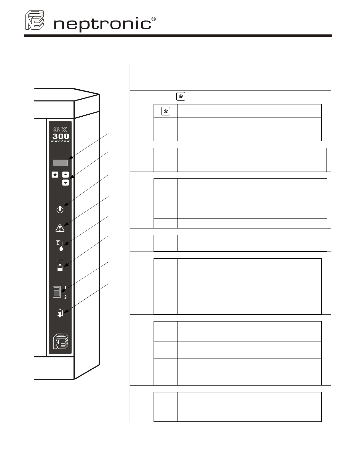
9. Front panel display features
Alphanumeric Display:
Indicates all operation parameters and the error messages
1
(see section 14 – Trouble shooting).
SK300 Humidifier
User Manual
Push button
2
1
2
3
3
4
4
5
6
5
7
8
(Illus. 51)
6
7
8
''POWER'' indicator
ÑOÒ
O The humidifier is disconnected from the power supply.
"CHECK" indicator
ÑOÒ
ÑOÒ
blinking
"FILL" indicator
"STEAM" indicator
Switch "AUTO/OFF/DRAIN"
Indicator "DRAIN"
O No abnormal conditions of operation.
ÑOÒ Indication that the water supply (fill) valve is open.
O Indication that the water supply (fill) valve is closed.
ÑOÒ
ÑOÒ
blinking
O There is no steam being produced.
AUTO
OFF
DRAIN
ÑOÒ
O Drain valve is closed.
, and
M button:
Used to access into program mode.
Up and Down button:
Used to increase or decrease the controlled
parameters of the humidifier.
The humidifier is powered by electricity and the switch is
at the AUTO position.
The "CHECK" indication is normally off. It will go on as a
warning against abnormal conditions of operation. For
details consult the Alphanumeric Display
(see section 9.1.3 Diagnostic mode).
Maintenance is required. The Running hours have
exceeded the Service hours. (see section 12 – Service).
ON/OFF model, the STEAM indicator lights when the
contactor is closed and steam is being generated.
Modulating model, the STEAM indicator blinks ON
and OFF in proportion to the percentage of steam
output the humidifier is generating. (The proportion is
displayed on the alphanumeric display (1)). For 100%
the indicator will be lit with no blink.
Position AUTO (I):
Humidifier will generate steam based on demand from
the humidistat.
Position OFF (O):
Humidifier will shut off.
Position DRAIN:
Humidifier will stop operating and the evaporation
chamber will drain the water out. This will be done
tipically at regular service.
Drain valve is opened, whether as a result of an
automatic drain cycle or because the front panel
switch is manually set to DRAIN.
22
Page 25
SK300 Humidifier
User Manual
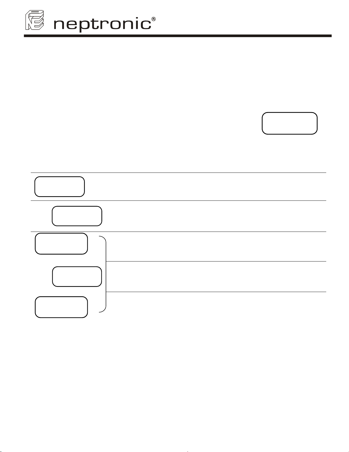
9.1. Description display modes
9.1.1. ''OFF'' Mode
When the rocker switch is in the ''OFF'' position, the display shows the model of the
humidifier and the program version number.
NEP 3.3
SK310M
(Illus. 52)
9.1.2. Scroll Mode
When the rocker switch is in the auto position, the display scrolls the following information every 6 seconds:
Display Description Comment
RH 25%
DCT 68%
lb/hr
ALARM
LEVEL
CONTROL
LEVEL
30
Display Space and Duct
Relative Humidity readings.
Quantity of steam produced
by the humidifier
Low water level.
Water level is controlled The water supply valve is activated below this level.
Only on modulating humidifiers (suffix M).
If no High limit Duct sensor is installed second line is
left blank
I.e.: The actual output of the humidifier at that
moment is 30 lb/hr.
Below this water level, the humidifier shuts off and
the water supply valve is activated until sufficient
level is reached.
HIGH
Water at maximum level. The water supply valve is automatically deactivated.
LEVEL
23
Page 26
SK300 Humidifier
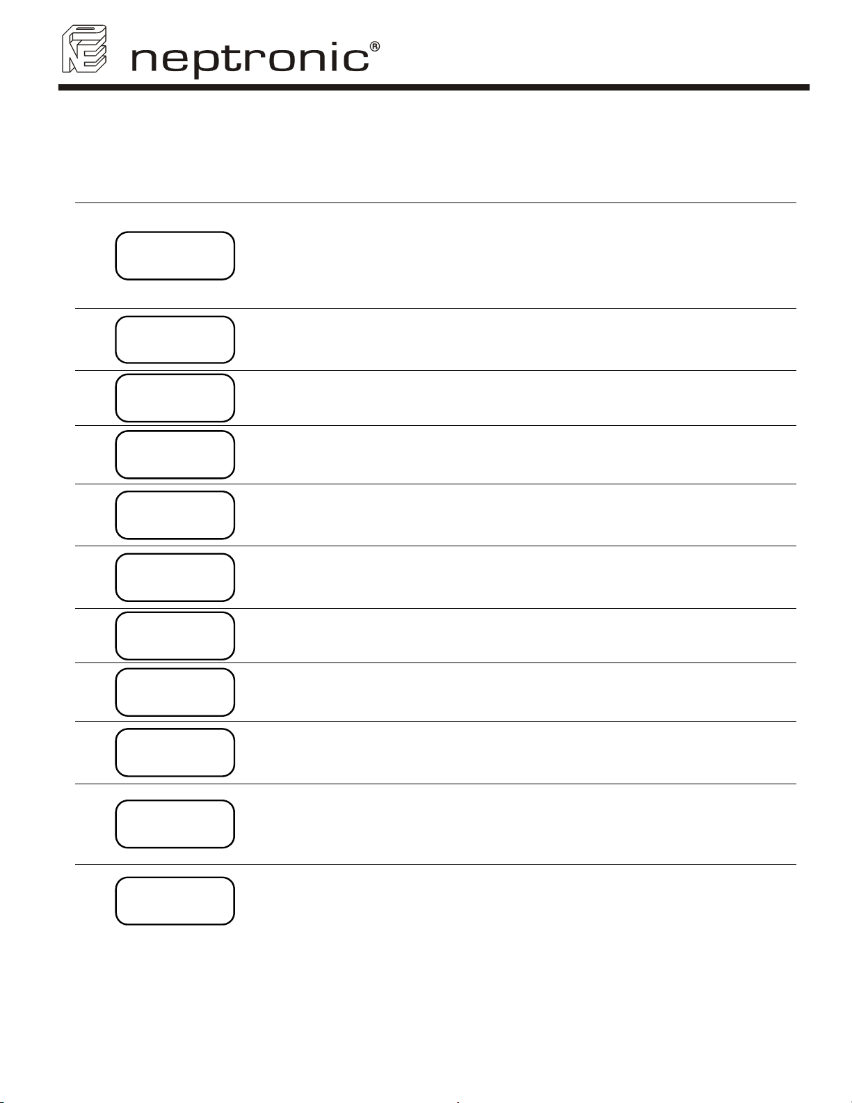
9.1.3. Diagnostic mode
When the following conditions occur, the diagnostic messages override the scrolling information:
Display Description Comment
Modulating humidifier: No analog signal to the
humidifier.
NO
DEMAND
No demand
On/Off humidifier: Humidity level has exceeded the
set point of the humidistat or humidity level has
exceeded the set point on the high limit humidistat or
airflow is not detected by the air pressure switch.
User Manual
SAFETY
OPEN
DRAIN
CYCLE
CONTACT
DELAY
OVER
HEATED
PROBE
DEFECTED
NO
LEVEL
FOAMING
CYCLE
Humidity level has exceeded the set point on the high
Safety open
Drain cycle The humidifier is in the automatic drain mode.
Contact delay
Overheated
Defected probe
No water Water has not reached the level probe
Drain foam
limit humidistat or airflow is not detected by the air
pressure switch (modulating humidifier only).
15 second delay for the power contactor to be
activated.
The temperature inside the container has exceeded
the boiling temperature. The humidifier has
automatically shut off.
The water level sensor is not operational. The
humidifier has automatically shut off.
AFEC (Anti Foam Energy Conservation) detects foam.
The humidifier drains for a few minutes and returns to
normal operation.
DRN/PROB
BLOCK
Verify
RH Sens
Verify
DCT Sens
24
Drain or probe block
Verify RH sensor
Verify Duct sensor
The humidifier drains but the water level does not
decrease, the humidifier has automatically shut off.
Signal from either HRM-X or HDM-X used as space
sensor is lower than 0.49 Vdc to terminal # 6 of
humidifier.
There might be a connection problem or a defective
sensor.
Signal from HDM-X used as Hi limit duct sensor is
lower than 0.49 Vdc to terminal # 4 of humidifier.
There might be a connection problem or a defective
sensor.
Page 27
SK300 Humidifier
User Manual
9.2. Programming
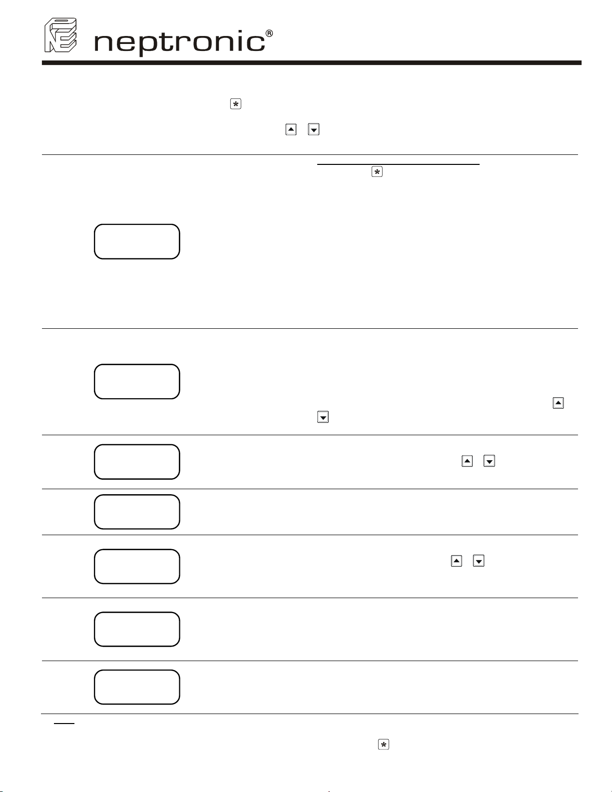
To enter into programming mode, please push button at any time, to advance the program function to the next programming step
in the menu push the same button twice.
Unless other instructions, you can make a selection by using
Step Display Description Comment
Set point RH origin
Out: Output set point to HRM
or HDM.
Int: Internal.
Value : from 00 to 100%
Default: Out 30%
Set point VAV allows Hi limit
Duct humidity control
OFF: Duct humidity control
disable.
65%: High limit Duct
humidity set point value.
Default: OFF
Prop Band allows the set up
of proportional band.
From 3 to 9%
Default: 3%
Drain frequency.
From 1 to 24 hours
Default: 4 Hrs
01
02
optional
03
optional
04
SETPOINT
OUT 30%
SETPOINT
VAV OFF
PROPBAND
3%
DRAIN
8 HRS
& buttons on control panel.
To enable set point to humidifier display
• Press the
will appear.
• Press and hold the TEST button located on Main Pc board
inside electrical compartment for 10 seconds.
• Release the TEST button then press the RESET button on the
same main pc board. Set point is now displayed on the
humidifier display.
If Output is selected, the set point is sent from the humidifier to the
humidistat HRM or HDM.
If HRM-X or HDM-X is connected with humidifier, please select
Internal, this will allow you to set up RH set point directly from
Humidifier.
To switch between Output and Internal Set point:
Press and hold the TEST button located on Main Pc board
inside electrical compartment until the change of the value.
If Set point VAV is disabling, no humidity signal from the VAV Duct
will be considered. If a Set point VAV value is set, the humidity
output will be controlled by both space and High limit duct humidity
signal.
To allow Set point VAV value:
Press and hold the TEST button located on Main Pc board inside
electrical compartment until OFF is disappeared.
You can then select the VAV Set point value desired by using
buttons on control panel.
Note: This Step will appear only if Internal has been selected at step 01
Proportional band can be set from 3% to 9% of the humidity set
points values (Space and High limit duct).
Select the appropriate value by using
panel.
Note: This Step will appear only if Internal has been selected at step 01
Choose the initiation of a drain cycle for 1 to 24 hours.
In general, harder the water is, more often the drain cycle should
be.
Drain cycle setting does not affect the AFEC system.
button to reach step 5, the RUNNING message
& buttons on control
&
05
06
07
Note: Any changes made in the Program Mode are saved into a non-volatile memory.
25
RUNNING
0645HRS
SERVICE
1000HRS
LOCK ON
80% PWR
When the humidifier is anywhere in the Menu Driven Program Mode, the normal operation of the humidifier is halted.
To resume normal operation, exit the menu program mode by pressing the
(This happens after step 7)
Number of running hours
Information only, no
possible set up.
Hour span between
servicing.
From 400 to 1500 hours.
Default: 1000 Hrs
Output Span.
From 00 to 100%.
Default: 100%
The humidifier has operated 645 hours since the last service.
After service, press simultaneously
to reset the number of hours of operation to zero. This procedure
will stop the CHECK indicator from flashing.
You can set the number of hours of operation before the humidifier
will call for service (blinking of CHECK light every 4 seconds) from
400 to 1500 hours.
In general, harder the water is, lower the number of hours of
operation before service should be.
This option is available only on modulating model.
i.e.: In this case, the humidifier will deliver 80% of its maximum
rated output when at full demand.
button until the alphanumeric display is clear.
& buttons for 15 seconds
Page 28
SK300 Humidifier
User Manual
10. Control p.c. board
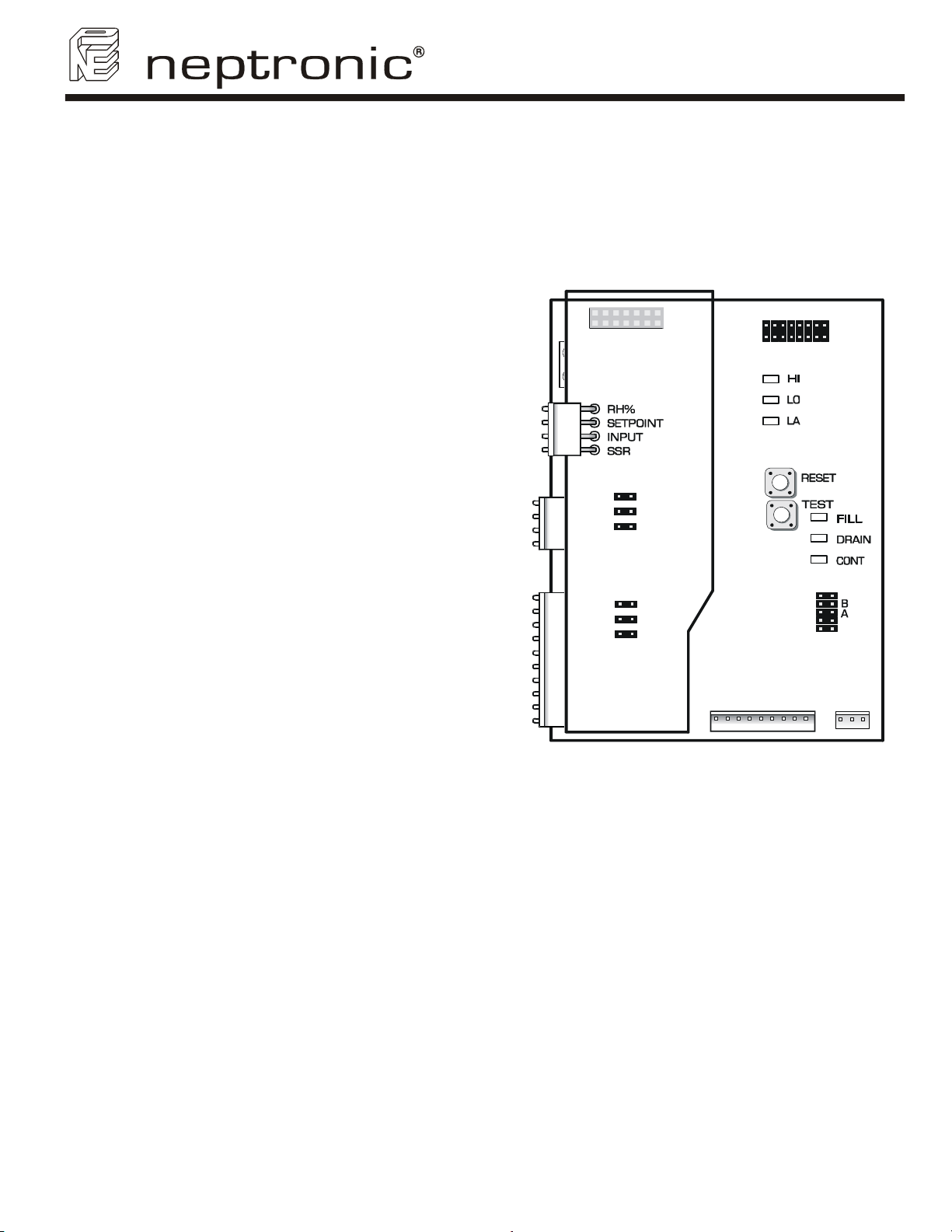
• The Printed circuit board designated ''PCB970819" is common to all SK300 series humidifier, ON/OFF or
modulating, this pc board is equipped with an advanced microprocessor which controls all the humidifier
functions.
• The Printed circuit board which is directly connected onto the main pc board is installed only on modulating model
(suffix M).
10.1. Main p.c. board
• There are 3 water level L.E.D.’s in the upper right
hand side. They indicate the relative water height as
sensed by the water level sensor.
o If HI is illuminated: water supply valve shuts off,
o If LO is illuminated: An evaporation chamber
filling is ordered, water supply valve opens.
o If LA is illuminated: No water is detected by the
water level sensor, the power to the elements is
shot off.
• The 3 status L.E.D.’s at the center left side operate
as follows:
o FILL indicates that the water supply valve is
feeding water.
o DRAIN indicates the drain valve empties the
container.
o CONT indicates that power is supplied to the
elements and the humidifier is producing steam.
• TEST button should be used when commissioning
the humidifier; this will initiate a preprogrammed
start-up cycle. The start up cycle cleans the supply
water and the evaporation chamber (see section 11
– start-up). This button enable also the set point
control of the humidistat to humidifier display (see
section 9.2 –Programming) (this is available only on
Modulating model).
• RESET button enable the bypass of start up
sequence.
CONTROL
INPUT
4-20mA
0-10V
2-10V
HUMIDITY
INPUT
4-20mA
2-10V
0-10V
TOP PCB
MODULATING
(Illus. 53)
PCB970819
REV. C
10.2. Modulating p.c. board
• The 3 jumpers at the center of the p.c. board (Control Input) are used for proper selection of the incoming
control signal. See section 8.2.4 - Control signals.
• The 3 jumpers at the bottom of the p.c. board (Humidity Input) are used for proper selection of the incoming
humidity signal. See section 8.2.3 – Humidity signals.
26
Page 29

SK300 Humidifier
User Manual
11. Start up procedure
We recommend to strictly following this start-up procedure in order to avoid any anomaly resulting from wrong cleaning
of the components.
In case of problem or discrepancy see section 14 – Trouble shouting guide.
1. Make sure that mechanical, electric and plumbing connection are done and secured.
2. Make sure that low voltage control circuit is done and correct.
3. Turn on the water shut off valve (outside of the humidifier) and check that the drain connections are connected
to the main drain line of sufficient diameter.
4. Turn on the power to the humidifier from the circuit breaker disconnect. The POWER indicator should go on.
5. Push the TEST button located on the main pc board. This pc board is located in the electrical compartment.
6. This will start up a pre-programmed start-up cycle. This start-up cycle will test functions of the humidifier and will
flush out any dirt in the humidifier and supply lines.
This cycle will last about 1 hour.
Note:
a) the front panel rocker switch will not affect the performance of the start-up cycle.
b) In the case of modulating humidifier, there must be a demand signal of at least 50% for the start-up cycle to
operate correctly.
c) To bypass at any time the start-up cycle and to proceed directly into normal operation, press the RESET
button located on the main pc board.
7. The front panel rocker switch may be left in the AUTO position during the start-up cycle. This will result in normal
operation of the humidifier as soon as the start-up cycle is finished.
8. Your humidifier is now fully operational.
27
Page 30
12. Service
12.1. General
• The humidifier is set to give service demand on the alphanumeric display and on the CHECK light after is
has reached the service hours setting (see section 9.2- Programming).
• The routine service is a cleaning of the evaporation chamber.
• We recommend setting the service demand depending on the water quality, the frequency of automatic
drain cycles and the demand placed on the humidifier.
• The manual cleaning frequency can be from every 2 months to once a year.
12.2. Evaporation chamber cleaning
WARNING: RISK OF BURN. THE EVAPORATION CHAMBER AND ITS CONTENT CAN BE EXTREMELY
HOT, CHECK TEMPERATURE BEFORE HANDLING.
1. Cool down evaporation chamber
• Set the front panel switch ''AUTO/OFF/DRAIN'' to DRAIN. The humidifier will command a drain cycle.
• Ensure that the evaporation chamber is completely empty. When it is empty, set the front panel switch
''AUTO/OFF/DRAIN'' to AUTO, the evaporation chamber will be fill with cool water; the FILL light will be illuminated.
• As soon as the evaporation chamber is full of cool water, the FILL light will extinguish, Set the front panel switch
''AUTO/OFF/DRAIN'' to DRAIN again.
• At the end of this drain cycle, check the temperature of the evaporation chamber, to do so, open the front door of
the humidifier and touch the evaporation chamber with the back of your hand, If it is cool enough you can go the
sequence #2 if not repeat the cool down operation until it will be cool enough.
• Set the front panel switch ''AUTO/OFF/DRAIN'' to OFF
2. Shut down of the electrical supply
CAUTION
• Turn off the main power supply to the humidifier.
3. Disconnection of heating element(s)
• Remove the high voltage connector located at the top right hand side of the mechanical compartment.
o Model SK302 to 306: Unscrew the connector.
o Model SK310 to SK360: squeeze the locking ears of the high voltage connector and pull it apart.
4. Disconnection of the other accessories.
• Disconnect the connector from the water level sensor; this connector is attached to a cable that enters the
mechanical compartment just below the high voltage connector. Squeeze the locking ear of the connector and pull it
apart.
• Remove the connection to the high limit sensor (klixon), located on the top cover of the evaporation chamber.
5. Disconnection of steam hose and water pipe
• Remove the steam hose(s) at the top of the evaporation chamber.
• Remove the water drain/fill connection to the evaporation chamber. To do this, unscrew the nipple located on the
lower right hand side of the evaporation chamber.
6. Removing the evaporation chamber
• The evaporation chamber may now be freely removed from the humidifier cabinet.
• CAUTION
yourself.
• Make sure that your footing is secure when lifting out the evaporation chamber. On large humidifier (SK340 and
SK360) it may weigh more than 35 lb (15 Kg). This operation may require another person to assist you in removing
the evaporation chamber.
7. Opening of the evaporation chamber
• Remove the cover from the evaporation chamber.
o Model SK302 to 306: Unlatch the 3 latches located around the evaporation chamber, caution: these latches
o Model SK310 to SK360: Turn the latches of the 4 or 8 latches located around the evaporation chamber.
• Remove the cover from the evaporation chamber.
SK300 Humidifier
User Manual
: RISK OF ELECTRIC SHOCK. SHUT DOWN THE ELECTRIC SUPPLY OF THE HUMIDIFIER
: The evaporation chamber still contains 1 inch of water, ensure that you do not reverse this water on
are very tight, we recommend you to help you with a screwdriver or pliers to do this.
28
Page 31
SK300 Humidifier
User Manual
8. Cleaning of the evaporation chamber
• Pour out any remaining water and scale that is on the bottom of the container
• To clean out the remaining scale from the container, use a stiff brush (synthetic filament only) and some vinegar or
any weak acid for cleaning stainless steel.
• WARNING: The use of wire brush or any non-recommended acid will void the warranty.
• If the amount of scale to remove is very important, the service demand frequency is too low for the quality of supply
water, you should then adjust this service demand frequency (see section 9.2 – Programming). Too much scale
may impair the normal operation of the humidifier or damage it; in this case warranty will be voided.
9. Cleaning of the other components
• The components installed on the cover (heating element and water level sensor) and the cover itself should be
cleaned as necessary, only if some scale has been accumulated on them.
• Proceed as per the cleaning of the container (step #8).
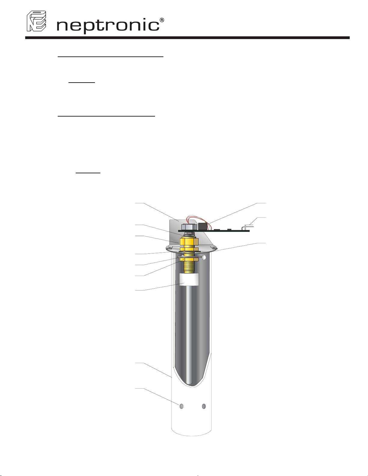
• Removing and cleaning of the water level sensor.
A chamber protects the water level sensor. Cleaning of the sensor requires removing this chamber.
o Unscrew the 2 screws holding the chamber, located on the cover.
o Carefully remove the chamber, do not touch or damage the water level sensor.
o Clean out the water level sensor by using a clean soft cloth.
CAUTION
: The water level sensor is covered by a thin lay of Teflon, any scratch or damage to this lay of Teflon
may provoke failure of the humidifier.
o Clean or the chamber by proceeding as per the main container (see step #8).
o
Re-attach the clean chamber to the cover and screw in the 2 screws on the top of the cover.
Probe protector
Spacer
Adjustement
potentiom eter
Terminal
connector
Compression
fitting
G askets
Brass washer
Nut (a)
T e flon nu t (b)
W ater le vel se n s o r
chamber
IM P O R T A N T :
A lw a y s ke e p th e
openings clean, water
m ust flo w th ru.
Cover of
evaporation
cham ber
(Illus. 54)
29
Page 32
SK300 Humidifier
User Manual
10. Re assembly of the evaporation chamber
• Rinse out the container and the cover with water.
• Check the cover gasket, and make sure that the gasket is well placed before to re-install the cover on the container.
The water level sensor should be in front of the drain/fill connection of the evaporation chamber.
• Tighten the latches around the cover (3,4 or 6).
• Replace the evaporation chamber in the humidifier.
• Tighten the water drain/fill connection nipple.
• Replace the steam hose(s) on the outlet of the evaporation chamber.
• Reconnect the connector of the water level sensor, high temperature switch (klixon) and the high voltage connector
of the heating element.
CAUTION
UNPROPER CONNECTION MAY PROVOKE ELECTRIC ARCS.
: RISK OF FIRE. MAKE SURE THE HIGH VOLTAGE CONNECTOR IS PROPERLY LOCKED. AN
11. Start-up of the humidifier
• Turn on the main power supply to the humidifier.
• The POWER light of the front panel should be illuminated.
• Press the button to enter the programming mode, to reset the Running hours (see section 9.2-Programming
Step 5).
• Set the front panel switch ''AUTO/OFF/DRAIN'' to AUTO. The humidifier will command to fill the evaporation
chamber with water; the FILL light should be illuminated.
It is possible that the CHECK light will illuminate because the evaporation chamber is empty. This signal will
extinguish as soon as the normal condition will be reach.
• If there is a humidity demand, the humidifier will produce steam again.
30
Page 33
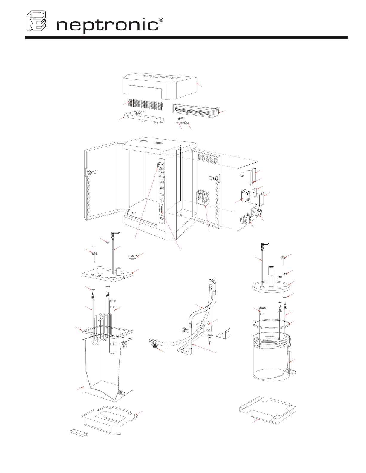
13. Exploded view & Bill of Material
13.1. Exploded view
SK300 Humidifier
User Manual
SDU Cabinet
Plastic gril
Steam Trap Assembly
G
I
F
W
XY
U
V
T
AA
S
R
P
N
J
H
B
O
Q
J
I
G
B
F
(Illus. 55)
M
Z
L
Evaporation chamber base
SK302 to SK306
D
C
A
DE E
C
K
A
Evaporation chamber base
SK310 to SK360
31
Page 34
SK300 Humidifier
User Manual
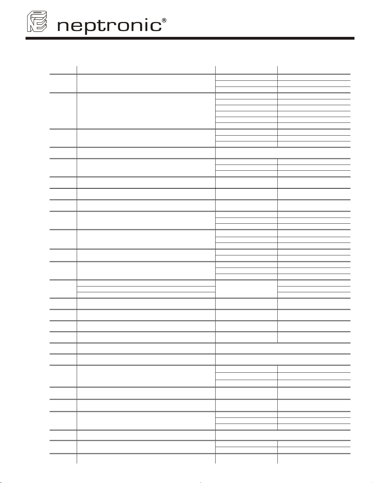
13.2. Bill of material
Item Description Model Part number
SK302 to 306 SW CONTSMA-ASSY
SK310 to SK330 SW CONTMED-ASSY
SK340 & SK360 SW CONTLAR-ASSY
SK302 to 306 (1 phase) SP 4018-M
SK304 to 306 (3 phases) SP 4019-M
SK310 & SK314 SP 4183A
SK320 & SK330 SP 4183B
SK340 SP 4186
SK360 SP 4185A
SK302 to 306 SP 1008
SK310 to SK330 SP 1021
SK340 & SK360 SP 1022
SK302 to 306 SP 4196-M
SK310/314/320/340 SP 4197-M
SK330 & SK360 SP 4198-M
SK302 to 306 SW FOAMSM-ASSY
SK310/314/320/340 SW FOAMMED-ASSY
SK330 to SK360 SW FOAMLG-ASSY
SK302 to 306 SW PROBSM-ASSY
SK310/314/320/340 SW PROBMD-ASSY
SK330 & SK360 SW PROBLAR-ASSY
SK302 to SK360 SP 6003
With IDC SP 6007
SK302 to 306 SW TRAPSMA-ASSY
SK310 to SK330 SW TRAPMED-ASSY
SK340 & SK360 SW TRAPLAR-ASSY
SK302 to SK360
SP 1024
A
B
C
D
E
F
G
H
I
J
K
L
M
N
Container of evaporation chamber
Cover of evaporation chamber
Evaporation chamber gasket
Heater element See table below
Level sensor chamber
Washer (elements) SK302 to SK360 SP 1005
S/S hex. Jam nut (elements) SK302 to SK360 SP 2330
High temperature switch (klixon) SK302 to SK360 SP 3035
Foam sensor
Water level sensor
Water supply valve
Fill and drain trap assembly
Silicone tubing ½” SP 1023A
Silicone tubing ¾” SP 1023B
PCV tubing 5/8”
Alphanumeric display SK302 to SK360 SW SK300DISPL-ASSY
O
P
Q
R
S
T
U
V
W
X
Y
Z
32
''AUTO/OFF/DRAIN'' rocker switch SK302 to SK360 SW SKSWITCH-ASSY
Terminal block and high voltage connectors SK302 to SK360 /
Cooling fan SK302 to SK360 SP 3007
Transformer See table below
Contactor See table below
50 A SP 3102
Solid State Relay
Main printed circuit board SK302 to SK360 NW SK300MAIN-TEST
Modulating printed circuit board SK302 to SK360 NW SK300MODULSS
SDU fan
Transformer See table below
Fuse inside SDU
Drain valve SK302 to SK360 SP 6010
100 A SP 3103
125 A SP 3105
SDU I SW FANSDU1-RET
SDU II SW FANSDU2-RET
SDU III SP 3010
SDU I and SDU 2 SP 5105
SDU 3 SP 5106
Page 35
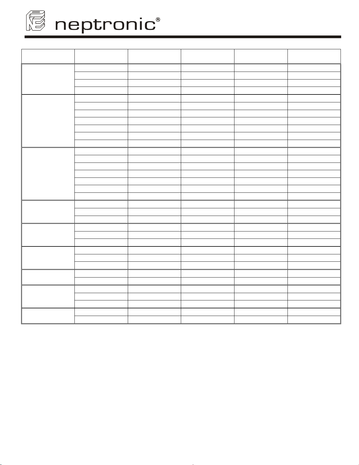
Model
SK302
SK304
SK306
SK310
SK314
SK320
SK330
SK340
SK360
Voltage
240V/1∼
208V/1∼
480V/1∼
600V/1∼
240V/1∼
208V/1∼
208V/3∼
480V/1∼
480V/3∼
600V/1∼
600V/3∼
240V/1∼
208V/1∼
208V/3∼
480V/1∼
480V/3∼
600V/1∼
600V/3∼
208V/3∼
480V/3∼
600V/3∼
208V/3∼
480V/3∼
600V/3∼
208V/3∼
480V/3∼
600V/3∼
480V/3∼
600V/3∼
208V/3∼
480V/3∼
600V/3∼
480V/3∼
600V/3∼
SK300 Humidifier
User Manual
D
Heater element
SE 5932 SP 3309 SP 3029 SP 3312
SE 5933 SP 3300
SE 5934 SP 3320
SE 5935 SP 3340
SE 5937 SP 3309
SE 5940 SP3300
SE 5924 SP3300 SP 3080 SP 3305
SE 5941 SP 3320 SP 3029 SP 3329
SE 5923 SP 3320 SP 3080 SP 3329
SE 5942 SP 3340 SP 3029 SP 3349
SE 5925 SP 3340 SP 3080 SP 3349
SE 5938 SP 3309
SE 5943 SP3300
SE 5933 SP3300 SP 3080 SP 3305
SE 5944 SP 3320 SP 3029 SP 3329
SE 5934 SP 3320 SP 3080 SP 3329
SE 5945 SP 3340 SP 3029 SP 3349
SE 5935 SP 3340 SP 3080 SP 3349
SE 5959 SP 3300 SP 3100 SP 3305
SE 5958 SP 3320 SP 3080 SP 3329
SE 5957 SP 3340 SP 3080 SP 3349
SE 5946 SP 3300 SP3220 SP 3305
SE 5947 SP 3320 SP 3080 SP 3329
SE 5948 SP 3340 SP 3080 SP 3349
SE 5949 SP 3300 SP 3027 SP 3351
SE 5950 SP 3320 SP 3100 SP 3352
SE 5951 SP 3340 SP 3100 SP 3353
SE 5952 SP 3320 SP 3220 SP 3352
SE 5939 SP 3340 SP 3100 SP 3353
SE 5949 SP 3308 SP 3027 SE 5950 SP 3320 SP 3027 SE 5951 SP 3340 SP 3027 -
SE 5952 SP 3321 SP 3220 SE 5939 SP 3340 SP 3027 -
R
Transformer
S
Contactor
SP 3029
SP 3029
SP 3029
SP 3029
SP 3029
SP 3029
SP 3029
X
SDU Transformer
SP 3305
SP 3329
SP 3349
SP 3312
SP 3305
SP 3312
SP 3305
33
Page 36
SK300 Humidifier
User Manual
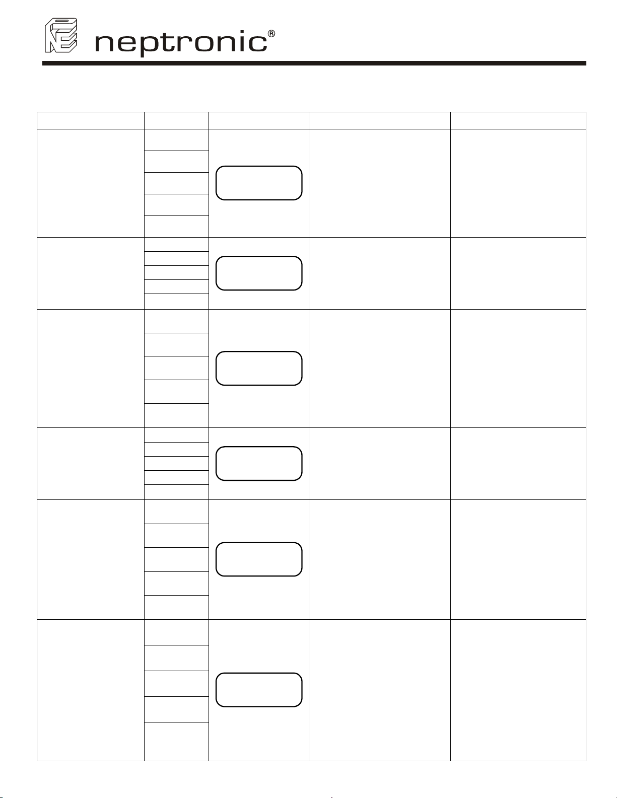
14. Trouble shouting guide
Problem Indicator Display Causes Corrective actions
• The humidifier is not
powered.
• The low voltage fuse is
open.
• The high temperature
switch is open.
• Wires harnesses inside the
humidifier are not secured
properly.
• The rocker switch is at the
OFF position.
• Wire harness from the LED
display panel to the Main
pc board is not secured
properly.
• Modulating humidifier: no
analog signal.
• On/Off humidifier: no
demand from humidistat or
air flow is not detected by
air pressure switch or high
limit humidistat is open.
• Control wires are not
properly secured to the
terminal blocks.
• Air flow is not detected by
air pressure switch or high
limit humidistat is open.
• Control wires are not
properly secured to the
terminal blocks.
• Humidifier is filling with
water and has not reached
or is not reaching the high
of the water level sensor.
• Humidifier is not filling with
water.
• Excessive foaming
condition inside the
evaporation chamber.
• Foaming sensor is
grounded.
• Check for the main power
supply and fuses.
• Check the transformer,
the low voltage fuse.
• Check the high
temperature switch, the
wires harnesses and the
Main pc board.
• Press the rocker switch to
the AUTO position.
• Check the white color wire
harness.
• Press the RESET button
on the Main pc board.
• Verify the setting of the
humidistat.
• Check the fan operation.
• Check the operation of the
high limit humidistat.
• Verify the connections of
the wires to the control
terminal blocks.
• Check the fan operation.
• Check the operation of the
high limit humidistat.
• Verify the wires to the
control terminal blocks #1
& 2.
• Verify if the drain valve is
manually open.
• Check if the shut off valve
on the water supply line is
open.
• Verify the operation of the
fill valve.
• Check the fill valve
strainer and the external
strainer are not blocked.
• Verify the quality of the
supply water.
• Verify if chemical products
were used to clean the
evaporation chamber
during maintenance.
Rinse with water the
chamber properly.
• Check the setting of the
Drain cycle. Reduce the
time between Drain
cycles.
Humidifier does not
operate
(Power Off)
Humidifier does not
operate
(Power On)
Humidifier does not
produce steam
(No Demand)
Humidifier does not
produce steam
(Safety Open)
Modulating
humidifiers only
No water inside the
evaporation chamber
Or
Humidifier will not
stop draining
Humidifier is always
on Foam cycle
Power: Off
Check: Off
Fill: Off
Steam: Off
Drain: Off
Power: On
Check: Off
Fill: Off
Steam: Off
Drain: Off
Power: On
Check: Off
Fill: Off
Steam: Off
Drain: Off
Power: On
Check: Off
Fill: Off
Steam: Off
Drain: Off
Power: On
Check: On
Fill: On
Steam: Off
Drain: Off
Power: On
Check: Off
Fill: On
Steam: Off
Drain: On
NEP 3.0
SK310M
NO
DEMAND
SAFETY
OPEN
NO
LEVEL
FOAMING
CYCLE
34
Page 37
SK300 Humidifier
User Manual
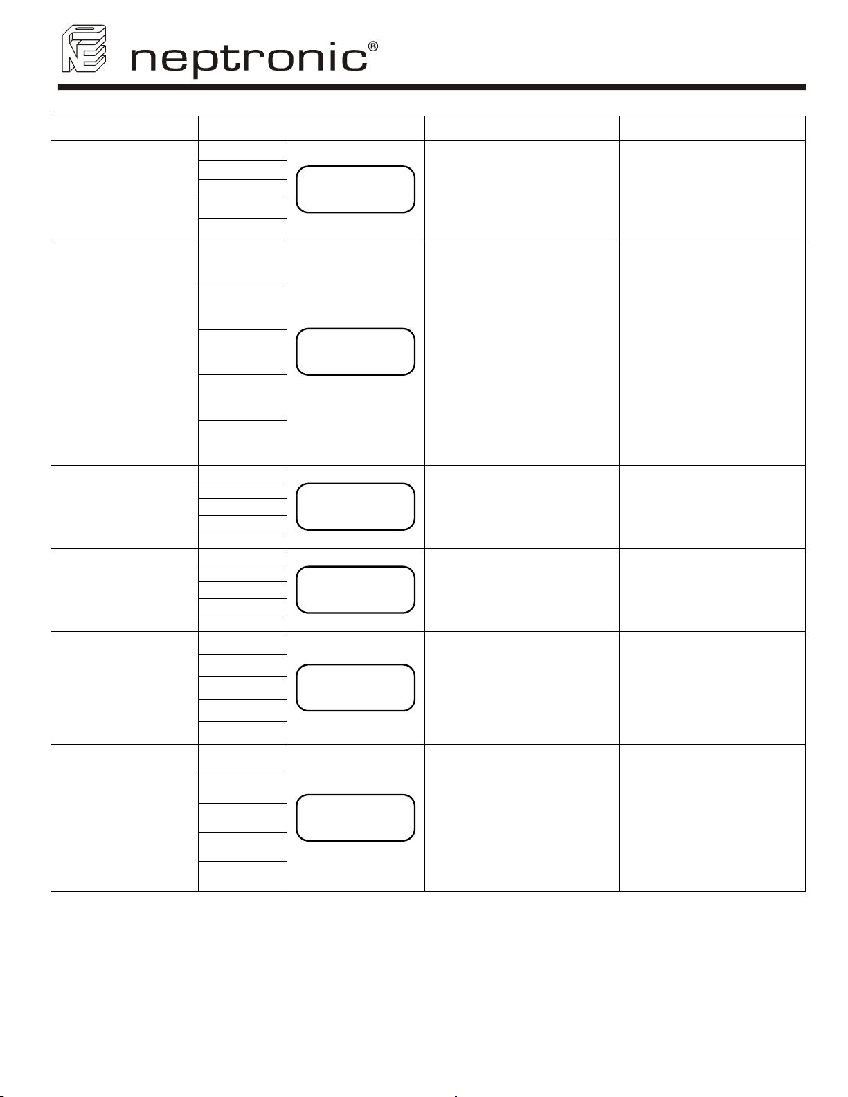
Problem Indicator Display Causes Corrective actions
• Service the evaporation
chamber, see section 14.
• Reset the Running hours
to cancel the blinking of
the CHECK light, see
section 9.2 STEP 5.
• Verify if the humidifier was
operating below the
standard water level then
replace the item J.
• If connector was removed
while powered was still
ON then press on the
main pc board the TEST
button until the Drain light
is ON then press RESET
once.
• Verify the connection of
the brown wire to the
Main pc board.
• Replace the water level
sensor, item J.
• Verify the drain valve, the
fill and drain water pipe
connection, the water
level sensor chamber are
not obstructed.
• Call factory for trouble
shooting instruction.
• Adjust the contrast of the
display.
• Verify the connections of
the ribbon cable are
properly secured and on
the right side (red line on
cable).
• Replace the LCD display,
item N.
Humidfier is
operating and the
CHECK light is
blinking
Humidifier is not
operating and the
CHECK light is ON
Humidifier is not
operating and the
CHECK light is ON
Humidifier will not
drain
Humidifier does not
operate and display
is blank
Humidifier is
producing steam and
display is blank
Power: On
Check: Blink
Fill: Off
Steam: On
Drain: Off
Power: On
Check: On
Fill: Off
Steam: Off
Drain: Off
Power: On
Check: On
Fill: Off
Steam: Off
Drain: Off
Power: On
Check: On
Fill: Off
Steam: Off
Drain: Off
Power: On
Check: Off
Fill: Off
Steam: Off
Drain: Off
Power: On
Check: Off
Fill: Off
Steam: On
Drain: Off
SCROLL
MODE
OVER
HEATED
PROBE
DEFECTED
DRN/PROB
BLOCK
• The Running hours have
exceeded the Service
hours.
• The electronic temperature
sensor inside the water
level sensor had sensed
abnormal temperature.
• The quick connector to the
water level sensor was
removed while the
humidifier was operating.
• The brown wire connected
to the top left corner of the
Main pc board is not
properly secured.
• The water level sensor is
damaged.
• During a Drain or Foaming
cycle, the water level
sensor has sensed the
water level has not
decreased.
• The following components
can be the cause of this
problem: water level sensor
(item J), main pc board
(item U), modulating pc
board (item V) or the LCD
display (item N).
• The potentiometer contrast
is set at the lowest setting.
• The display ribbon cable is
not connected properly.
• The LCD display is
defective.
35
Page 38
SK300 Humidifier
User Manual
Personal notes
36
Page 39

1. General
Unless otherwise arranged, in writing, the acceptance of the
Order Confirmation by the purchaser includes acceptance of the
"General Conditions of Sale and Warranty" of National
Environmental Products, Ltd hereafter referred to as NEP.
2. Incoterms
The international rules for interpretation of trade terms
"Incoterms" as defined by the ICC Incoterms publication no. 460
from 1990, shall apply to the commercial terms used herein.
3. Confirmation of Order
• NEP shall not be deemed to have accepted an order until
written "Order Confirmation" from NEP is issued to the
purchaser.
• It is the responsibility of the purchaser to verify that all
information concerning his/her order is correct and to notify
NEP In writing, of any discrepancy prior to the order being
shipped. In the event of a change or correction to an existing
order, a second "Order Confirmation" will be issued by NEP.
4. Price
• Our prices are net, Ex-works Montreal in U.S. Currency, unless
stated otherwise.
• Minimum orders shall be $50.00 minimum.
• Shipping and Handling charges are $5.00 minimum per order
unless the shipment is billed to the purchaser's account or
shipped freight collect.
• NEP reserves the right to adjust accepted prices in the event of
alterations in rates of exchange, variations in costs of materials,
changes in wages, interference on the part of the Government
or similar conditions over which NEP has no control.
5. Payments terms
• Major credit cards, C.O.D., Prepayment.
• For open account, invoices are payable within 30 days from the
date of invoice without no deduction, unless specify otherwise.
• An interest charge of 2% per month will be included on all
overdue payments.
• No new order will be process if invoices are not paid within 45
days.
6. Transfer of ownership
The goods shall remain the property of NEP until the full
payment for the goods has been received by NEP.
7. Delivery terms
• Shipments are Ex-works 400 Lebeau, St Laurent, Quebec,
H4N 1R6, CANADA unless notified otherwise.
• Unless special instructions, the order will be delivery in the way
which NEP deems best without guaranteeing this to be the
cheapest way of transport.
• For International Order, a written designation naming the
freight forwarding agent is required and will remain in effect
until notified otherwise.
• Any discrepancy, damage or breakage should be reported in
writing both to NEP and to the Carrier within 5 working days
from the receipt date.
8. Risk
From the moment of delivery, the purchaser shall bear all risks
for the goods and NEP shall not be responsible for loss and
damage incurred during transportation.
9. Delivery time
• Delivery time is stated approximately and depends on the
product ordered, please allow a minimum of:
a) 2 weeks for processing North American order.
b) 6 weeks for processing International order.
• We will make every effort to adhere to our delivery promises,
but will not accept order or contract cancellation or any liability
for any direct or indirect losses that may arise for any reason
whatsoever as a result of our failure to adhere to such
promises.
SK300 Humidifier
General conditions of sale & warranty
10. Return of good
• Goods received by the purchaser cannot be returned unless
a completed "R.M.A. Form" (Return Material Authorization
Form) has been issued by NEP's Customer Service.
• Any returned goods must be sent to NEP 400 Lebeau, St
Laurent, Quebec, H4N 1R6, CANADA, unless stated
otherwise by the R.M.A. Form, accompanied with the
completed "R.M.A. Form", the R.M.A. number shall be
prominently displayed on the shipping box. Unauthorized
returns will be refused.
• Any returned goods must be sent freight prepaid. Any goods
that come to us freight collect will be refused and returned to
sender unless previously agreed to by us in writing on the
"R.M.A. Form".
• Goods returned for credit shall be in condition for resale in the
original box and properly packaged. Units, accessories or
components that have been installed are not returnable and
not refundable.
Credit is subject to an overhead charge of 30% of the invoice
plus shipping & handling if returned within 30 days of the
invoice date and 50% from 30 to 60 days.
• Non standard product (SK units with special feature),
Multisteam manifolds and any DI unit are not returnable and
not refundable.
11. Warranty
• Provided that the terms of payment are observed, the
purchaser is offered a warranty of 24 months from the
original purchase date of delivery for any NEP's standard
product, provided the equipment has been properly installed
and operated in accordance with NEP instructions.
• The warranty covers faulty manufacture, design and/or
defective materials and is limited to the equipment and
components. The warranty shall cease to be valid in the
event of misapplication, incorrect installation, improper
maintenance or any other incorrect uses or misuse of the
product.
• For the SK series, the warranty furthermore ceases to be
valid if the user disconnects or removes any electronic or
mechanical components prior disconnecting the input power.
NEP assumes no responsibility for repairs made on
equipment, unless performed by NEP's authorized personnel.
• The defective product or component shall be returned in
accordance with the paragraph 10 (Returns of goods) as
described in this document.
• NEP agrees under the warranty to repair or replace (at the
discretion of NEP) such standard product or component,
which upon examination by NEP are found to be defective.
• Product or component replaced or repaired under warranty
will be sent back to the purchaser, standard freight paid by
NEP
• Expenses in connection with travelling time, dismantling and
mounting shall not be paid by NEP
• Guarantee for products or components sold but not
manufactured by NEP, is only given to the same extent as
given to NEP, however, not exceeding the normal NEP
warranty.
• Parts used for repairs are warranted for the balance of the
term of the warranty on the original humidifier or 90 days,
whichever is longer.
• Any repair made, after the original warranty period, at the
NEP facilities are warranted for 1 month from the date of
repair.
12. Proper law and jurisdiction
This contract is and shall be deemed to have been made in the
province of Quebec, CANADA, and shall in all respects, be
governed by the province of Quebec laws.
37
 Loading...