

Page 1
Control Equipment
PTCPTC
PTC
PTCPTC
PTC
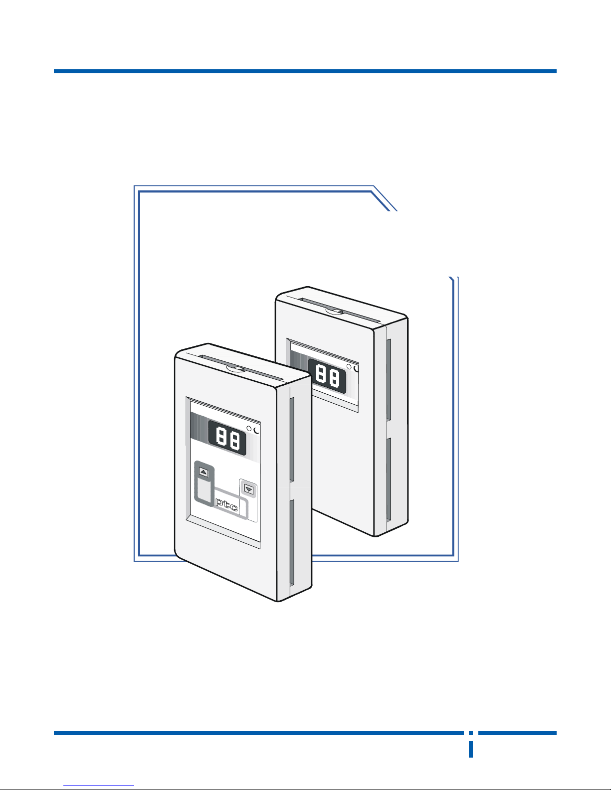
modulating wall
thermostat
neptron
c
PAGE 1NEP04/03 www.hvacquick.com 877-711-4822
Page 2
Control Equipment
specifications:specifications:
specifications:
specifications:specifications:
PTC
power input:
power consumption:
signal outputs:
output impedance:
ambient temp:
setpoint range:
deadband:
proportional band:
control algorithm:
nsb input:
nsb override:
nsb algorithm:
minimum position:
tpm period:
tpm range:
tpm 2 inhibit input:
contact outputs:
external sensor:
display type:
default display:
programming:
memory retention:
24 vac ±20%
2va minimum
17va maximum (all outputs used at maximum
current output)
0 -10 vdc, cooling
0 -10 vdc, cooling high demand
0 -10 vdc, heating
0 -10 vdc, heating high demand
2 TPM outputs, 1 or 24 to 29 vdc
0.5 - 5 vdc actual temperature
3 KΩ maximum, heating & cooling outputs
100 Ω maximum tpm output 1
250 Ω maximum tpm output 2
20 KΩ maximum actual temperature output
-200 to 500C (-40 to 1200F)
00 to 380C (320 to 990F)
0.30C (± 0.50F)
10 to 90C user programmable (20 to 160F)
P .I. integral and terms auto-tuned
contact closure, programmable for 0 to 150C
(00 to 270F) deadband expansion
2 hours
deadband expansion around setpoint. Opti-
mized soft start for peak electrical demand
reduction. Warm up ramp time programmable
over 0 to 99 minutes
0 to 75% independently adjustable for heating
and cooling outputs. Does not affect high
demand outputs.
2 seconds
tpm 1: 0 to 100% of heating demand
tpm 2: 50% to 150% of heating demand
contact closure to inhibit (set to zero) tpm 2
output regardless of demand
2 independent dry contacts (1 amp maximum
resistive load) independently programmable
for heating or cooling with selectable switching points from 20% to 90% of demand
optional DS100 duct or WS100 wall
2 digit led (7 segment type)
actual temperature selectable in 0C or 0F.
menu driven directly from thermostat
no external tools required.
10 years minimum
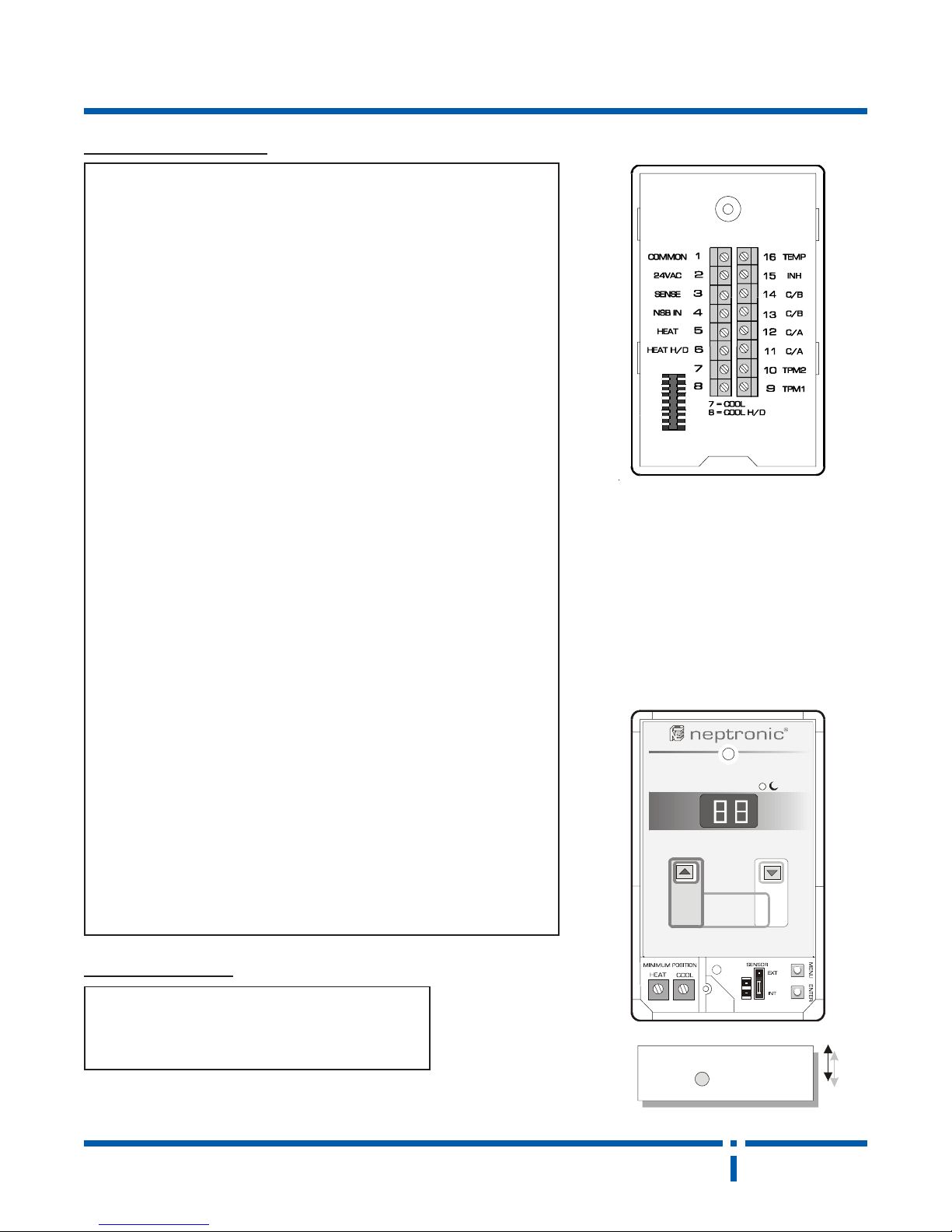
connections:
1. common
2. 24 vac
3. external sensor
4. nsb input
5. heating output
6. heating high
demand output
7. cooling output
8. cooling high
demand output
fig. #1
9. tpm 1 output
10. tpm 2 output
1 1. contact A
12. contact A
13. contact B
14. contact B
15 tpm2 inhibit input
16. actual temp. output
dimensions:dimensions:
dimensions:
dimensions:dimensions:
height:
width:
depth:
(120 mm) 4.73 in.
( 74 mm) 2.91 in.
( 23 mm) 0.90 in.
neptron
fig. #2
(access cover)
c
NEP04/03PAGE 2 www.hvacquick.com 877-711-4822
Page 3
Control Equipment
description:description:
description:
description:description:
The ptc is a powerful microprocessor based menu driven temperature controller for heating and cooling
applications. Please read the following information to maximize the potential of this powerful thermostat.The following
are some highlights of the ptc:
PTC
* p.i. analog heating and cooling outputs
* 2 sequential p.w.m. heating outputs to proportionally
drive solid state relays
* 2 fully programmable dry contact relays to be used in
heating and/or cooling applications
* high signal selections outputs from multiple ptc's to
be used by a master system
* individually programmable night set back/ set up
* night set back override
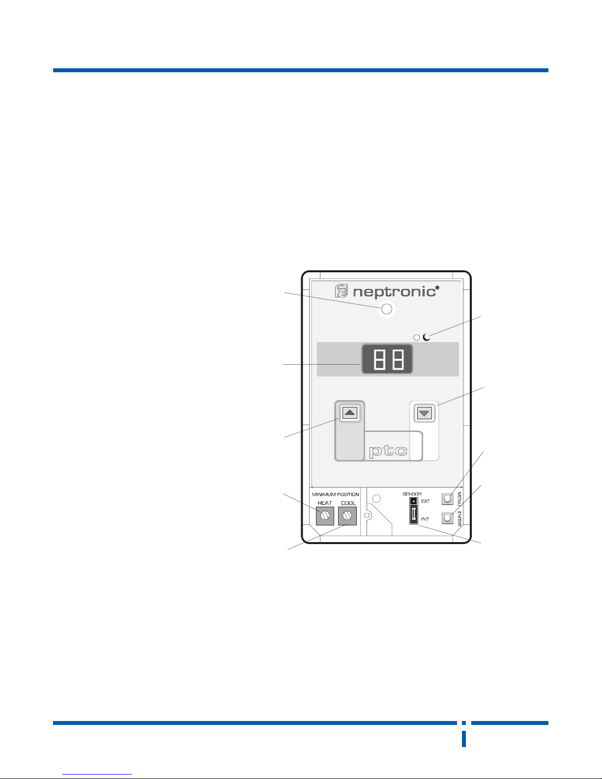
buttonbutton
button
buttonbutton
functions:functions:
functions:
functions:functions:
The up button is used to increase
the temperature set point (warmer)
while the thermostat is operating in
user mode. The up button is also
used to increase a given parameter
when in program mode.
Similarly , the down button is used
to decrease the temperature
setpoint (cooler) or decrease a
parameter in program mode.
The menu button is used to place
the ptc into program mode, and to
advance the program function to
the next menu.
hole for
mounting
screw
temperature
and function
led display
button
minimum
position
HEA T
* intelligent self-optimizing morning self start
* minimum position setting for heating and cooling output
* programmable min and max allowable temperature setting
* selectable internal/external sensor
* led display
* programmable Celcius or Fahrenheit display
* plug in easily removable thermostat body
* attractive flat casing
night
set back
indicator
down
button
up
menu
button
enter
button
The enter button is used to store
the program function parameter into
memory . Once a value is stored in
memory , the ptc will remember that
value even if the power is turned off
at the thermostat for several years.
When a parameter is being stored,
the led display will flash in a
circular fashion. You will notice that
when changing the setpoint, the led
display will do a circular flash. This
is because a new setpoint is being
entered into the memory of the ptc.
neptron
minimum
position
COOL
In program mode if this flash does
not occur you have not stored that
parameter into memory! if you do
not wish to change the value in memory of a parameter , simply do not
press the enter button and push
the menu button to go to the next
program level.
sensor
shunt
fig. #3
Night Set Back Indicator: When NSB
is ON, the NSB Indicator will light. If
you wish to locally override the NSB,
momentarily push either the UP or
DOWN button. NSB will be cancelled
for 2 hours and the NSB light will turn
off until the NSB is re-established.
exterior / interior
modes
c
PAGE 3NEP04/03 www.hvacquick.com 877-711-4822
Page 4
Control Equipment
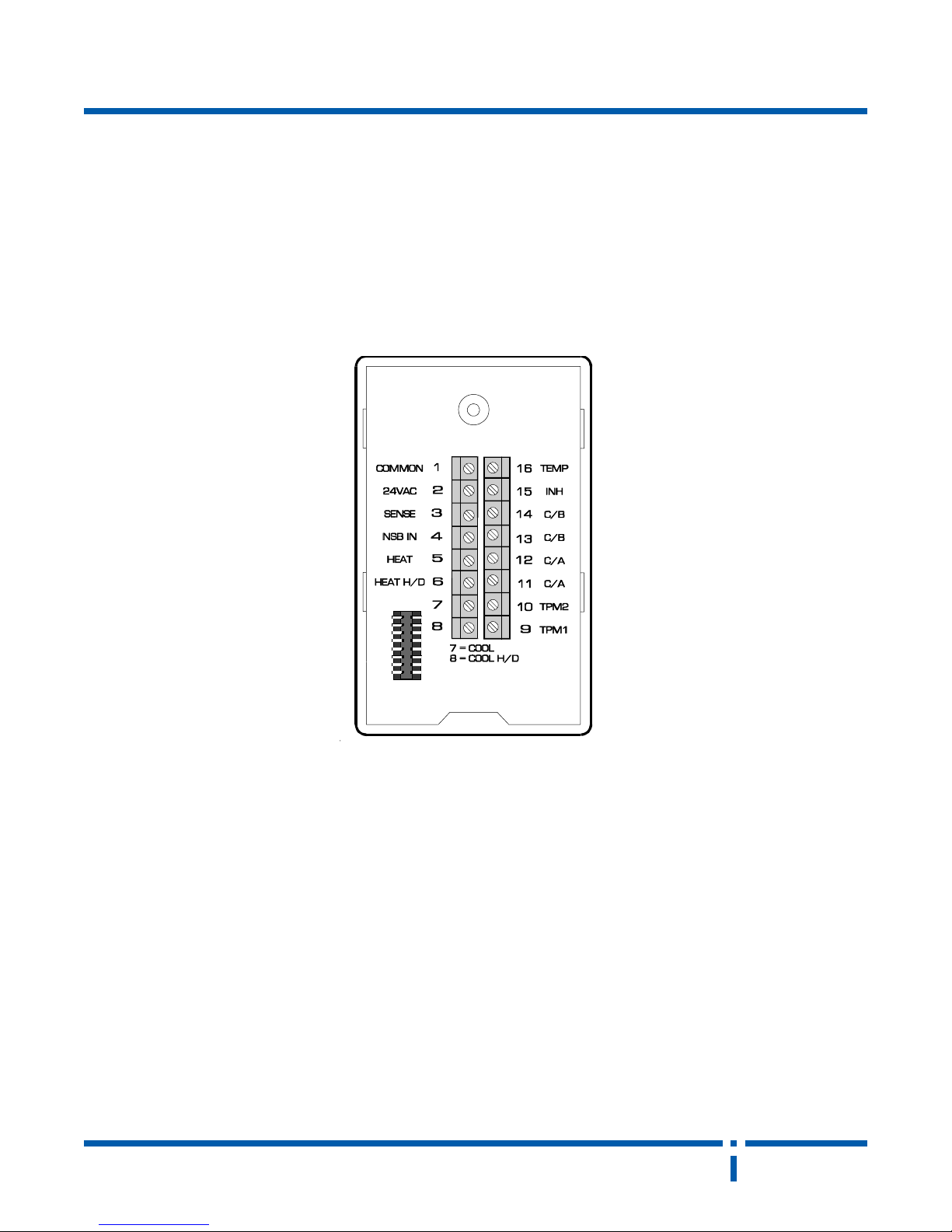
ptc terminal connection descriptions:ptc terminal connection descriptions:
ptc terminal connection descriptions:
ptc terminal connection descriptions:ptc terminal connection descriptions:
PTC
1 common
2 24 vac
3 external temperature sensor.
If an external temperature sensor
is used, it must be connected
between pins 1 and 3. When
using an external temperature
sensor, the sensor selection
jumper must be placed in the ext
position. Neptronic wall sensor
ws100 or duct sensor ds100 must
be used.
4 night set back input. To enlarge the deadband during unoccupied periods (night set back),
short pins 4 and 1. The amount
of deadband expansion is programmed at the thermostat.
5 heating output 0 to 10vdc.
This is the analog proportional
heating output. It may be used
to control an actuator.
6 heating high demand output 0
to 10vdc. This output may be
placed in parallel with many ptc
heating high demand outputs to
find the highest heating demand
among many zones. This signal
can be used to control a voltage
sensitive relay (ie; neptronic vrc2
or vrc4) in order to turn on a heat-
ing system via stages.
7 cooling output 0 to 10vdc. This
is the analog proportional cooling
signal. It may be used to control
an actuator.
fig. #4
8 cooling high demand output 0
to 10vdc. This output may be
placed in parallel with many ptc
cooling high demand outputs to
find the highest cooling demand
among many zones. This signal
can be used to control a voltage
sensitive relay (ie, neptronic vrc or
vrc4) in order to turn on a cooling
unit via stages
9 time proportional modulation
output 1; 1 or 24vdc. This heating
output may be used to modulate
heating elements via a triac switch
or solid state relay. The output
range is proportional to
0 to 100% of the heating demand.
This output is capable of supplying up to 100mA of current so it
may be used to actuate several
triac switches, or even a thermoelectric valve directly .
10 time proportional modulation
output 2: 1 or 24vdc output. This
output is similar to pin 9 except
that the output is proportional to
50 to 150% of the heating demand. In addition the maximum
current output is 100mA.
11 & 12 contact A. This contact is normally open. It will close
if the demand exceeds the programmed value. the contact rating is 120V 1A resistive.
13 & 14 contact B. This contact is normally open. It will close
if the demand exceeds the programmed value. The contact rating is 120V 1A resistive.
15 tpm 2 inhibit. This input,
when shorted to pin 1, will turn
off time proportional modulation
2 regardless of the heating demand.
16 actual temperature output,
0.5 to 5vdc. This output is proportional to the actual temperature seen by the thermostat. A
chart of temperature versus voltage is shown in fig #5. The output is high impedance and any
attempt to draw more than 0.5mA
from this output will result in incorrect readings and may result
in impro-per function of the ther-
mostat.
neptron
c
NEP04/03PAGE 4 www.hvacquick.com 877-711-4822
Page 5

Control Equipment
PTC
temp: vdc:
0
C
0230.5
1 43 9.4
25.538.4
3 5.73 7.4
4936.4
5 14 5.4
6344.4
7 5.44 2.4
85.641.4
9 84 0.4
01059.3
11 25 8.3
215.356.3
31 5.55 5.3
41754.3
51 95 3.3
61161.3
71 5.26 03
815.469.2
91 66 8.2
02866.2
12 07 5.2
225.174.2
32 5.37 3.2
42571.2
52 77 0.2
62979.1
72 5.08 8.1
825.286.1
92 48 5.1
03684.1
13 88 3.1
235.982.1
33 5.19 0.1
433969.
53 59 48.
637937.
73 5.89 26.
839925.
0
F
fig. #5
programming:
pmetV
All of the programming of the ptc is carried out at the thermostat. No programming tool is required, and the programming sequences are all menu driven.
Description of all programming steps is done in the order in which they appear
while actually programming the thermostat. Please look at fig. #3 for the
locations of up, down, menu, and enter buttons.
In many cases you will never need to program the ptc thermostat. The standard
factory settings are suitable for most applications. A list of the standard factory
settings are shown below. If you want to change any of these settings, follow
the directions in the next section.
ptc thermostat function and factory settings
functions standard factory setting
setpoint maximum 300C - 860F
setpoint minimum 150C - 590F
contact A close for >50% cooling demand
contact B close for >50% heating demand
night set back deadband 100C - 180F
proportional band 20C - 3.50F
soft start ramp time 00 minutes (off)
display type
calibration 0
0
C
neptron
c
PAGE 5NEP04/03 www.hvacquick.com 877-711-4822
Page 6
Control Equipment
PTC
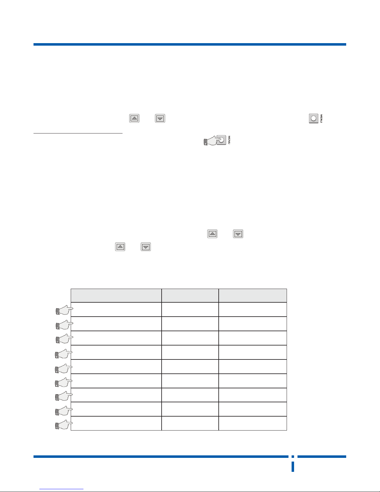
program level organization:
Each function is made of 2 steps:
Step 1 The function will be displayed for 2 seconds followed by message 2.
Step 2 is adjusted by pushing the up or down buttons. To change to the next function, press the MENU button.
If you wish to skip over a function, simply push and hold down the MENU button.
* Note: If you want to program all functions in 0F skip to message #8 "d l "
step 1 of each function will be displayed (in order) for 2 seconds, and then the ptc will skip to the next function.
ptc thermostat programming modes
When the ptc is turned on, it automatically displays the actual temperature in 0C. The thermostat is fully functional
and it uses default factory settings
Setpoint change - To check the setpoint momentarily press the UP or DOWN button. The display will automati-
cally show the setpoint.
To change setpoint press the UP or DOWN
button until the required
new set point is displayed.
T o change any other parameters of the thermostat, see all the programming levels as listed below in order of
apperance along with the display messages.
noitcnufmargorp yalpsidts1 yalpsidts2
1
2
3
4
5
6
7
mumixamtnioptes
muminimtnioptes
tnioptesAtcatnoc
tnioptesBtcatnoc
dnabdaedkcabtesthgin
dnablanoitroporp
).nim(emitpmartratstfos
IH
OL
AC
bC
bS
bP
tr
83ot0
83ot0
9C...2C,9H...,3H,2H
9C...2C,9H...,3H,2H
51ot0
9ot1
99ot0
8
9
neptron
epytyalpsid
noitarbilacerutarepmet
ld
LC
FroC
5ot5-
c
NEP04/03PAGE 6 www.hvacquick.com 877-711-4822
Page 7
Control Equipment
program level organization: cont.
PTC
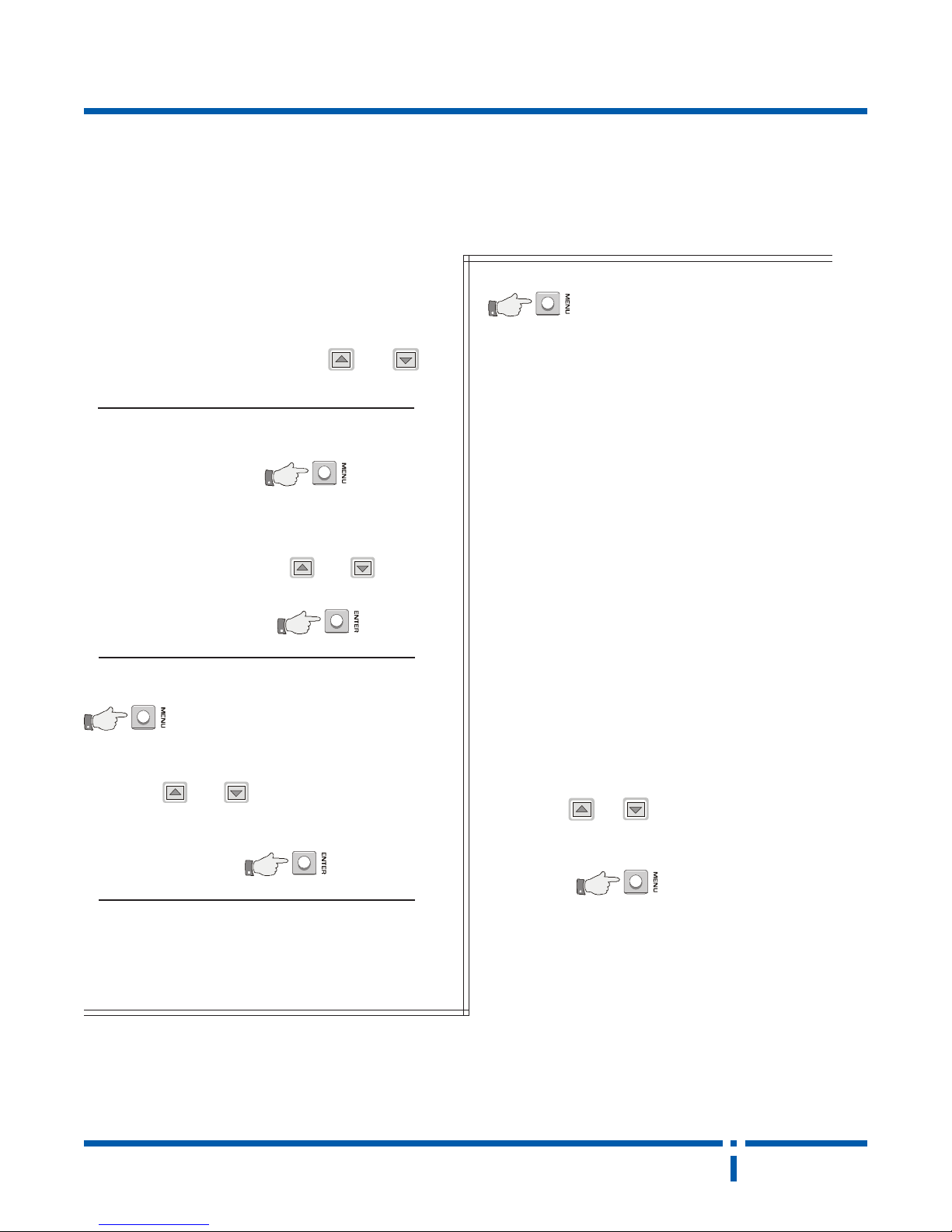
When the ptc is turned on. it is automatically in user
mode. In this mode only the setpoint may be changed
(within the limits set by the minimum and maximum
setpoint settings) by pressing the up or down
buttons.
T o enter program mode, push the MENU button once.
1
The first program level message ( hi ) will be displayed for 2 seconds, followed by the maximum
setpoint setting. Pushing the up or down buttons,
set the maximum setpoint you
wish the user to have access
to. Once that is done, push the ENTER button to
store this value in memory .
Push MENU once again. The second program level
2
Pushing the up or down buttons, set the minimum
message ( Lo ) will be displayed for 2
seconds, followed by the minimum
setpoint setting.
setpoint you wish the
user to have access to.
Push MENU again. The third program level message
( Ca ) will be displayed for 2 seconds,
3
followed by the setpoint of contact A. It
is displayed in the following format:
message contact setpoint
H2 heating at 20 % demand
H3 heating at 30 % demand
H4 heating at 40 % demand
H5 heating at 50 % demand
H6 heating at 60 % demand
H7 heating at 70 % demand
H8 heating at 80 % demand
H9 heating at 90 % demand
C2 cooling at 20 % demand
C3 cooling at 30 % demand
C4 cooling at 40 % demand
C5 cooling at 50 % demand
C6 cooling at 60 % demand
C7 cooling at 70 % demand
C8 cooling at 80 % demand
C9 cooling at 90 % demand
Pushing the up or down buttons will change the
Once that is done, push the ENTER button to store
this value in memory .
Note that if you wish to fix the temperature setpoint
to one value (ie; not adjustable by the user), set the
(hi) and ( Lo ) values to the desired temperature
setpoint.
neptron
contact setpoint. When you have arrived at the setpoint
you wish, push the ENTER button to store this value in
memory.
c
PAGE 7NEP04/03 www.hvacquick.com 877-711-4822
Page 8
Control Equipment
program level organization: cont.
PTC
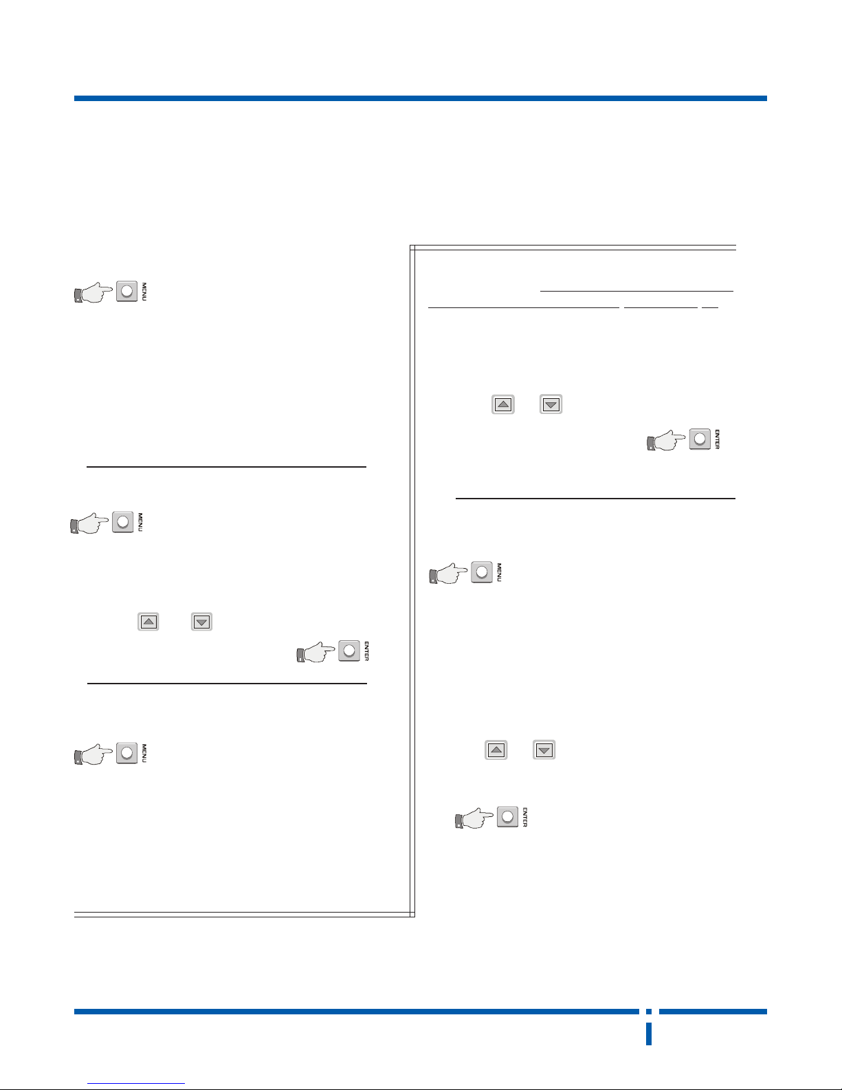
Push MENU again. The fourth program level mes-
4
contact B. The format is the same as described
above for contact A, and adjustments to the setpoint
are made in the same way .
Contact A and Contact B are totally independent.
You may select two heating contacts, two cooling
contacts, or one heating and one cooling contact.
Their setpoints can be wherever you choose.
Push MENU again. The fifth program level message
5
deadband. This is the total deadband (over and
under the setpoint) applied when the night set back
terminal is connected to common.
Using the up or down button, adjust the night set
store that value in memory .
sage ( C b ) will be displayed for 2 seconds, fol lowed by the setpoint of
( S b ) will be displayed for 2 seconds,
followed by the night set back
back deadband to the value
required and press ENTER to
will allow you to tailor the response of the ptc to any
given application. For most V .A.V applications, the
3
usual proportional band is 2 to 30C (3.5 to 5.50F ). For
many applications where hot or chilled water coil is
used, a typical proportional band is 3 to 6 degrees 0C
(5.5 to 10.50F).
Using the up or down buttons, adjust the propor tional band to the value re quired. Press the ENTER
button to store the value in memory .
Push MENU again. The seventh program level mes-
7
start feature is only useful if modulating electric heating
is used, you may disable this feature. To turn off the
soft start function, set the soft start ramp time to 00. If
modulating electric heating is used, normally the soft
start ramp time is set the same as the morning warm
up period.
sage ( r l c ) will be displayed followed by
the soft start ramp time. Since the soft
Push MENU again. The sixth program level message
6
The ptc operates using a p.i. algorithm, with the
integral terms optimized automatically by the thermostat. But since the proportional band has the
greatest effect on the output, adjusting the proportional band
( P b ) will be displayed for 2 se-conds,
followed by the proportional band.
neptron
Push the up or down buttons to set the soft start
ramp time to the number of
minutes required.
Push the ENTER button to store this value in memory .
c
NEP04/03PAGE 8 www.hvacquick.com 877-711-4822
Page 9

Control Equipment
program level organization: cont.
PTC
Push MENU again. The eighth program level mes-
8
shown in user mode. There are two choices: either
degrees Celsius (0C) or degrees Fahrenheit (0F).
T o normally display the temperature setpoint in Celsius, press the up or down button until ( C ) is
perature in Fahrenheit, press the
up or down button until ( F ) is displayed.
memory.
Push MENU again. The ninth program level mes-
9
adjustment.
sage (d l) will be displayed for 2 seconds, followed by the display type
displayed. T o normally
display the actual tem-
Push the ENTER button to store this
parameter in
sage ( C L ) will be displayed followed
by the temperature calibration
When finished, push ENTER to store the calibration
value in memory .
This is the last programming step. To put the ptc
thermostat back into user mode, push MENU once
again.
Note that if the ptc thermostat is left in program mode
the control section of the thermostat is not functional.
Therefore it is always a good idea to leave it in user
mode when you are finished programming.
Restoring the standard factory settings
If you wish to restore the standard factory settings on
the ptc, then follow these steps:
1) turn off the power to the thermostat. This may be
done by unplugging the ptc from the sub-base.
2) push and hold down the menu, enter, and up
buttons at the same time.
The ptc's temperature sensor is factory calibrated.
However you may wish to adjust this calibration, particularly if you are using an external temperature sensor. T o do this, simply measure the actual temperature in the room and compare it to the actual temperature displayed by the ptc.
If, for example, the ptc was reading 2 degrees lower
than the actual temperature, set the temperature
calibration adjustment to -2.
Adjust the calibration value by pushing the
up or down buttons.
neptron
3) turn the power back on to the ptc (or plug it back
into it's sub-base).
The thermostat must be at this point, in the program
mode if the MENU button was held down for too long.
To get back into user mode, push and hold down the
MENU button until you see the display show (C L).
Then release the MENU button, and
momentarily push the MENU button
once again.
c
PAGE 9NEP04/03 www.hvacquick.com 877-711-4822
Page 10
Control Equipment
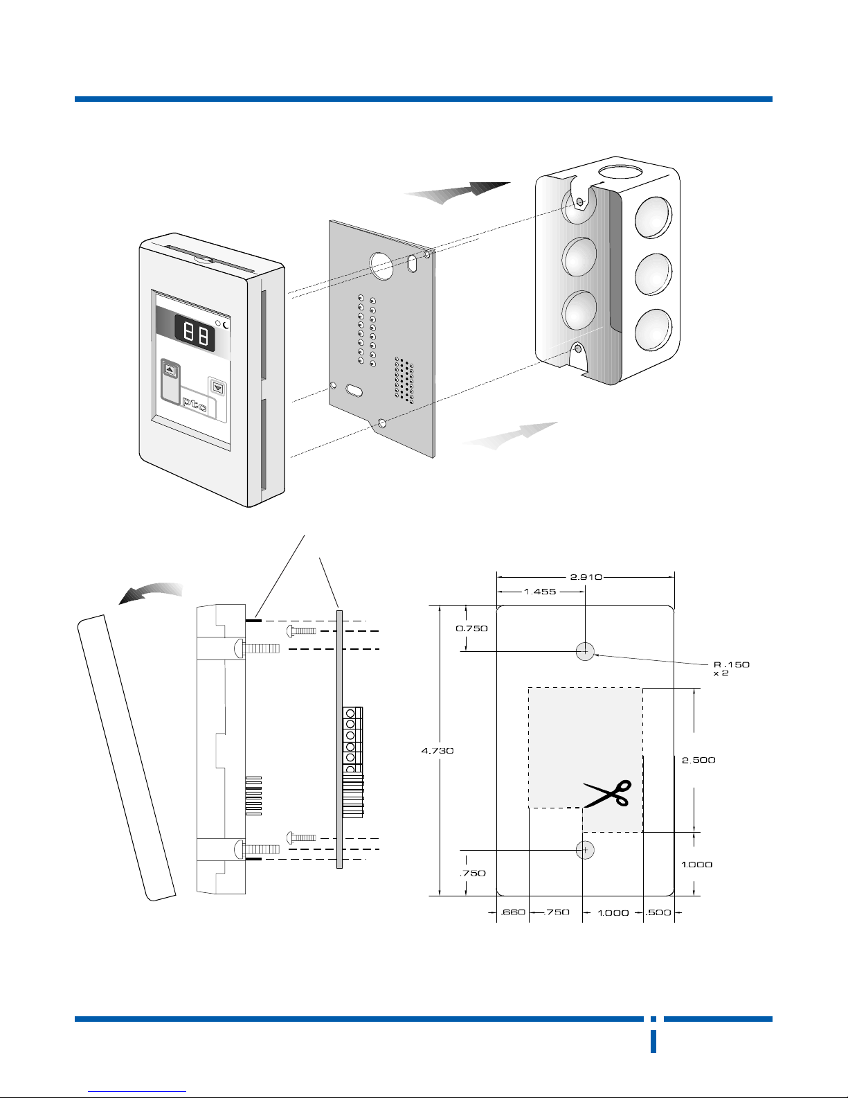
installation:
PTC
designed to fit on
standard 2020 electrical
box, thermostat box, or
directly on dry-wall.
ensured to align
pin guides with the baseboard for proper fitting.
to open:
grab top and bottom of
front cover and pull in a
downward direction.
neptron
dimensions for wall mounting.
(Suggested cut-out for terminal
block.)
c
NEP04/03PAGE 10 www.hvacquick.com 877-711-4822
Page 11
Control Equipment
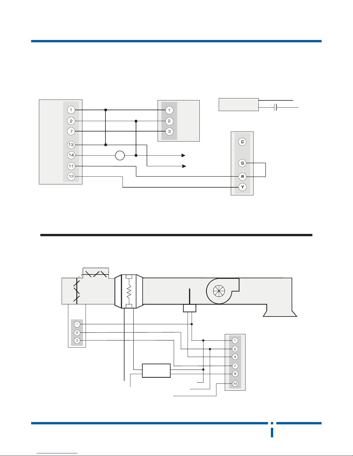
typical applications:
central cooling with baseboard heating (on/off)
R
ptc
modulating wall
thermostat
BBMS2000
damper
motor
Heater
cooling unit
T erminal strip
PTC
L1
L2
R
Fan on
24 hours
Notes:
use intermediate relay R for high current load (over 1A)
discharge air temp control with remote temp indicator
return
air
n.o.
fresh
air
bbms2000
(interlinked
push rods
and ball joints)
Notes: Set sensor select jumper to ext.
n.c.
damper
motor
with
duct
heater
triac
switch
L2
L1
.5 to 5 vdc remote
common
temp. indicator
ds100
-
+
24vac
ptc
modulating
wall
thermostat
neptron
c
PAGE 11NEP04/03 www.hvacquick.com 877-711-4822
Page 12
Control Equipment
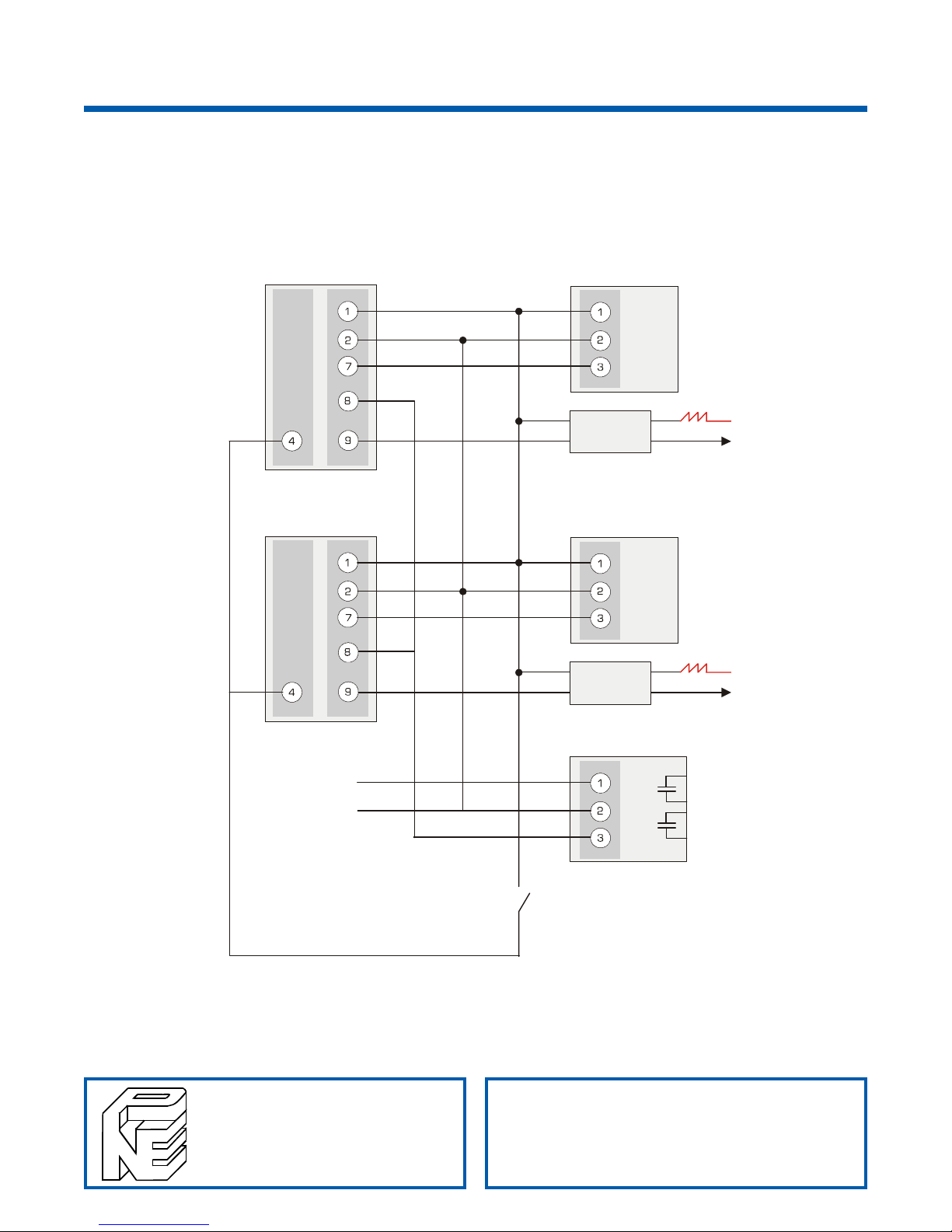
Two typical zone V A V box control. Cooling ramp s modulates V A V Box actuator ,
heating ramps modulates terminal reheat, high cooling demand cycles A/C unit.
(For any number of zones)
PTC
modulating
thermostat
ptc
modulating
wall
thermostat
ptc
wall
common
24vac
BBMS2000
damper
motor
-
triac
switch
+
-
triac
switch
+
VRC
heater
BBMS2000
damper
motor
heater
L2
L1
L2
L1
A/C stage 1
A/C stage 2
NATIONAL ENVIRONMENTAL PRODUCTS LTD., INC. MAINTAINS A POLICY OF CONTINUAL PRODUCT DEVELOPMENT; THEREFORE, IN THE INTEREST OF TECHNICAL
IMPROVEMENTS, THE FIRM RESERVES THE RIGHT TO CHANGE THE DESIGN, SPECIFICATIONS OR COMPONENTS OF THE EQUIPMENT WITHOUT PRIOR NOTICE.
national
environmental
products
montreal,canada
www.hvacquick.com 877-711-4822
NSB on when closed
NEP04/03
 Loading...