

Page 1
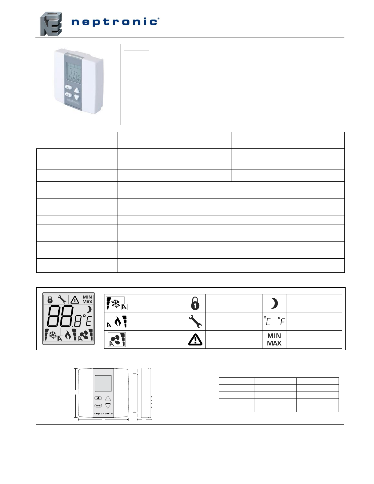
EFCB Thermostat
Specification & Installation Instructions
TFL(H)5x-180322.doc/111031 1
Technical Data
TFL54
TFLH54-xxx
Electrical connection
3 wire cable
3 wire cable
Setpoint range
10ºC to 40ºC [50ºF to 104ºF]
Temperature: 10ºC to 40ºC [50ºF to 104ºF]
Humidity: 10 to 65%RH
Control accuracy
Temperature: ±0.5ºC [0.9ºF] @ 22ºC [71.6ºF]
typical calibrated
Temperature: ±0.5ºC [0.9ºF] @ 22ºC [71.6ºF]
typical calibrated, Humidity ±3.5%
Power supply
From EFCB
Power consumption
1 VA
Display resolution
±0.1ºC [0.2ºF]
Proportional band
0.5ºC to 5ºC [1ºF to 10ºF] adjustable
Operating temperature
0ºC to 50ºC [32ºF to 122ºF]
Storage temperature
-30ºC to 50ºC [-22ºF to 122ºF]
Relative humidity
5 to 95 % non condensing
Housing degree of protection
IP 30 (EN 60529)
Weight
80 g. [0.15 lb]
Note
The TFL(H)5x can only work with the EFC. All the inputs/outputs are located on the EFC except
for the temperature sensor built-in the TFL(H)5x.
Interface
Display Symbols
Cooling ON
100% output
A: Automatic
Menu set-up lock
Energy saving mode
Heating ON
100% output
A: Automatic
Programming mode
(Technician setting)
or
ºC: Celsius scale
ºF: Fahrenheit scale
Fan ON
100% output
A: Automatic
Alarm status
Minimum/Maximum
setpoints
Dimensions
A
B
C
D
Dimension
Imperial (in)
Metric (mm)
A
3.00
78 B 3.00
78 C 1.00
24
D
2.36
60
Features:
Used to program/configure the EFCB Fan Coil controller
Attractive modern look with large LCD and backlight
Icon-driven information and 1 line of text information
3 wire cable between thermostat and EFCB controller
Selectable Fahrenheit or Celsius scale
Multi-level lockable access menu
Selectable internal or external temperature sensor
TFL54
TFLH54-xxx
Page 2
TFL(H)5x
Specification & Installation Instructions
2
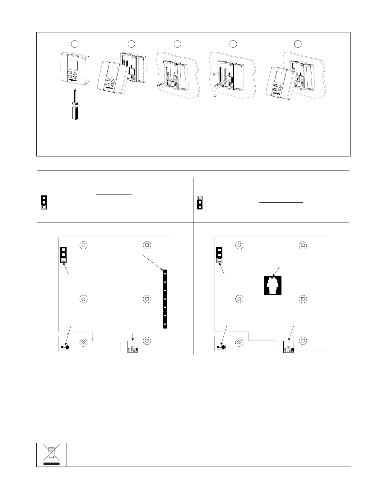
Mounting Instructions
BA C D E
CAUTION: Risk of malfunction. Remove power prior to separate thermostat cover (control module) from its base.
A. Remove the screw (captive) holding the base and the front cover of the thermostat.
B. Lift the front cover of the thermostat to separate it from the base.
C. Pull the cable through the base hole.
D. Secure the base to the wall using wall anchors and screws (supplied). Make the appropriate connections.
E. Mount the control module on the base and secure using the screw (from step A).
Settings on PC Board & Connections
Mode Selection (JP1)
PGM
RUN
JP1
Jumper (JP1) on RUN:
Thermostat is in Operation Mode.
Thermostat must be set in this mode to operate properly.
If not locked, setpoint, fan speed and control mode (Heating &
Cooling ON, Cooling only ON or Heating only ON) can be
modified by end user.
PGM
RUN
JP1
Jumper (JP1) on PGM:
Thermostat is set in Programming Mode.
Refer to following section about all settings description
TFL54 – 3 wire cable (TB5 #1, 2 & 3)
Connect TB6 #4 (A+) & #5 (B-) to EFCB for BACnet service port to work
TFL55 – RJ45 Ethernet cable
BACnet service port works only if TFL(H)5x is connected to EVCB
JP1
Mode selector
COM
PGM
Connecting
strip
COMM.
BUS
24V
Temperature
sensor
RUN
TB1
BACnet
service port
1 2 3 4 5 6 7
AI1
B-
A+
DI1
JP1
Mode selector
PGM
Temperature
sensor
RUN
BACnet
service port
RJ45 connector
Recycling at end of life
At end of life, please return the thermostat to your Neptronic® local distributor for recycling. If you need to find the nearest Neptronic®
authorized distributor, please consult www.neptronic.com.
 Loading...