

Page 1
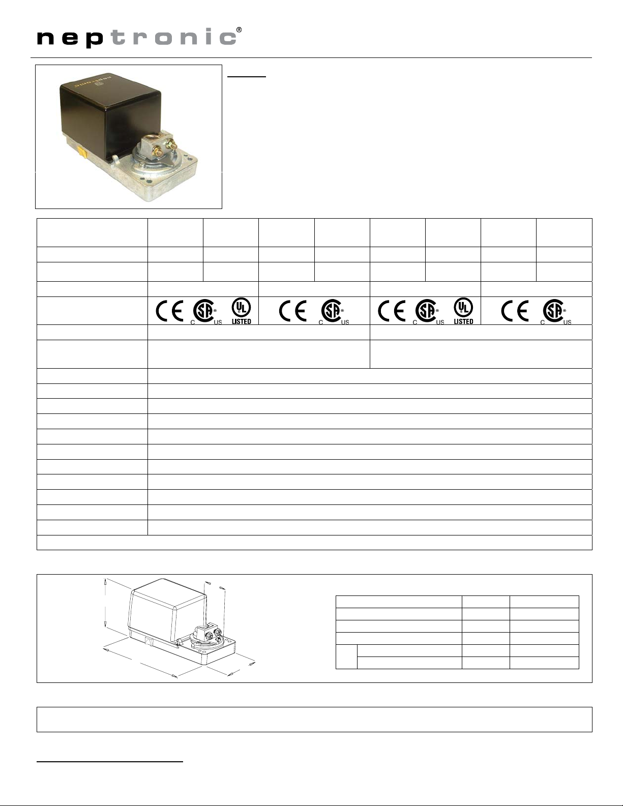
Actuator
Feature:
• Mounts easy on round
& square shaft (with option –8).
• External clutch for manual
adjustments.
• Maintenance free.
• Position indicator.
• Fail safe by Enerdrive System
(on model 60 & 80).
• Auxiliary switches
Technical Data
Fail safe - Enerdrive No Yes No Yes No Yes No Yes
Power consumption 6 VA
Power supply 22 to 26 VAC or 28 to 32 VDC 40 to 56 VDC 22 to 26 VAC or 28 to 32 VDC 40 to 56 VDC
Approvals
Auxiliary switches No Yes
Ingress protection
Torque 50 in.lb. [5,6 Nm] at rated voltage
Running time through 90º 90 - 110 sec (Fail-safe20-30 sec)
Electrical connection 18 AWG [0.8 mm2] minimum
Inlet bushing 2 inlet bushing of 5/8 in [15.9 mm] & 7/8 in [22.2 mm]
Control signal 2 to 10 VDC or 4 to 20 mA (factory set 2 to 10 VDC)
Angle of rotation 0 to 90 degrees, mechanically adjustable (factory set with 90º stroke)
Direction of rotation Reversible, Clockwise (CW) or Counterclockwise (CCW) (factory set with CW direction)
Ambient temperature -22ºF to +122ºF [-30º C to +50º C]
Storage temperature -22ºF to +122ºF [-30º C to +50º C]
Relative Humidity 5 to 95 % non condensing.
Weight 3 lbs. [1.4 kg]
BM000S BM060S BM800S BM860S BM020S BM080S BM820S BM880S
BBMS2000 BBMS2060 BBMS2800 BBMS2860 BBMS2021 BBMS2080 BBMS2821 BBMS2880
20 VA Peak,
6 VA
IP22 equivalent to Nema type 2,
IP54 equivalent to Nema type 3R if water tight inlet bushings
(not supplied NEP617) are installed
Warning: Do not press the clutch when actuator is powered
Dimensions
A
D
C
Caution
We strongly recommend that all neptronic® products be wired to a separate transformer and that transformer shall service only neptronic® products. This precaution will
prevent interference with, and/or possible damage to incompatible equipment.
When multiple actuators are wired on a single transformer, polarity must be observed. Long wiring runs create voltage drop which may affect the actuator performance.
(on model 20 & 80).
6 Watts
B
Specification & Installation instructions
Old Number
BBMS2000 BM000S
BBMS2021 BM020S
BBMS2060 BM060S
BBMS2080 BM080S
BBMS2800 BM800S
BBMS2821 BM820S
BBMS2860 BM860S
BBMS2880 BM880S
20 VA Peak,
6 VA
IP22 equivalent to Nema type 2
6 Watts
1.50 38.1
3.26 82.8
6.60 167.5
20 Watts Peak,
6 Watts
D
1
6 VA
Dimension Inches Metric (mm)
A
B
C
model 00 & 60 3.01 76.4
model 20 & 80 3.72 94.5
20 Watts Peak,
6 Watts
1
Enerdrive System U.S.A. Patent #5,278,454
1
BMS/070620
Page 2
BM000S/020S/060S/080S
BM800S/820S/860S/880S
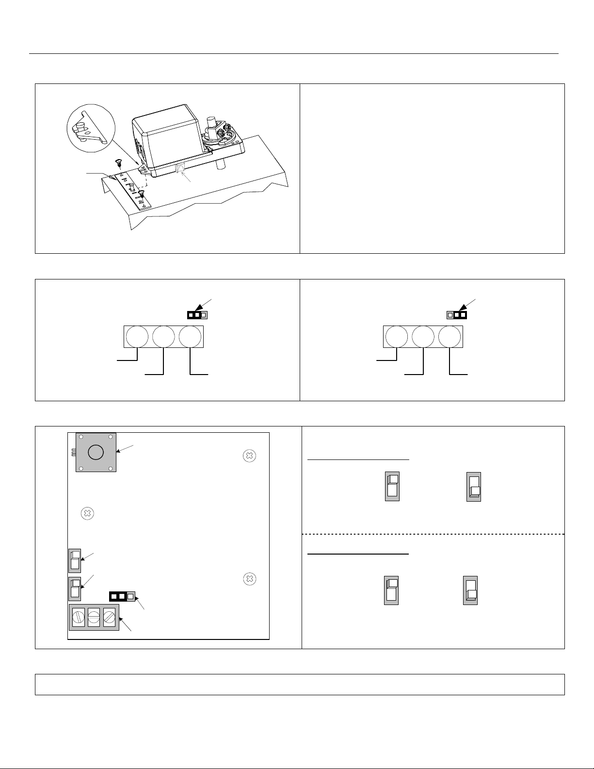
Mechanical installation
MOUNTING
BRACKET
Wiring Diagrams
Analog 2 to 10 Vdc
JP1
CLUTCH
Jumper at left
Specification & Installation instruction
1.
Manually close the damper blades and positioned the
actuator at 0º or 90º.
Slide the actuator onto the shaft.
2.
Tighten the nuts on the “U” bolt to the shaft with a 8mm
3.
wrench to a torque of 60 in.lb. [6,7 Nm].
Slide the mounting bracket under the actuator. Ensure free
4.
movement of the slot at the base of the actuator. The
bracket pin must be placed in the mid distance of the slot.
Fix the bracket to the ductwork with #8 self-tapping screws.
5.
Analog 4 to 20 mA
JP1
Jumper at right
COMMON (-)
PC Board
SW1
1 2 3
TB1
SUPPLY (+) 2 to 10 VDC
Potentiometer
Rotation direction
Fail safe direction
(only on model 60S & 80S)
JP1
SW2
Control signal
selection
BM060VAV
1 2 3
TB1
COMMON (-)
Dip switch settings
Rotation direction (SW1)
Fail safe direction (SW2)
(only on model 60S & 80S)
SUPPLY (+) 4 to 20 mA
CW
(0 to 90º)
Fail safe
return at 0º
CCW
(90 to 0º)
Fail safe
return at 90º
TB1
1 2 3
Terminal
Stroke adjustment
To adjust the stroke, move the adjustment screws at the desired position.
2
 Loading...