

NeoVision DVR AHD Operation Instruction Manual

NeoVision DVR AHD
H.264 Digital Video Recorder
Operation Instruction

Directory
1 Precautions ..................................................................................................................................... 4
2 Statement ........................................................................................................................................ 5
3 Introduction .................................................................................................................................... 6
3.1 Introduction ......................................................................................................................... 6
3.2 Product features ................................................................................................................ 6
3.3 Installation Guide .............................................................................................................. 7
3.3.1 Unpacking Inspection ............................................................................................ 7
3.3.2 Hard disk installation ............................................................................................. 7
3.3.3 Wiring Installation .................................................................................................. 7
3.4 Panel Introduction ........................................................ אי !מ יא ימי.
3.4.1 Front Panel Description ............................................. אי !מ יא ימי.
3.5 Mouse operation........................................................................................................ 8
3.6 Input Method ............................................................................................................. 8
3.7 Boot/Shutdown.......................................................................................................... 9
3.7.1 Boot .......................................................................................................................... 9
3.8 Screen icon .............................................................................................................. 10
3.8.1 Status Icons .......................................................................................................... 10
3.9 Real-time browser ................................................................................................... 11
4 Operations Guide ....................................................................................................................... 12
4.1 Right-click menu ................................................................................................................ 12
4.1.1 Screen switching .................................................................................................. 12
4.1.2 PTZ control ............................................................................................................ 12
4.1.3 Image Color .......................................................................................................... 13
4.1.4 Video inquiry ......................................................................................................... 13
4.1.5 Manual recording ................................................................................................. 13
4.1.6 Alarm output ........................................................................................................ 14
4.1.7 Main menu ............................................................................................................ 14
4.2 Main menu introduction ................................................................................................. 15
4.3 Video queries ................................................................................................................... 16
4.4 Configuration management ..................................................................................... 17
4.4.1 System configuration........................................................................................... 18
4.4.2 Video configuration ............................................................................................. 36
4.4.3 Network Configuration ........................................................................................ 28
4.4.4 Alarm configuration ...................................................................................... 32
4.4.5 User Management ................................................................................................ 19
4.4.6 Abnormal configuration ...................................................................................... 35
4.5 Storage Management ..................................................................................................... 24
4.5.1 Hard disk management ..................................................... אי !מ יא ימי.
4.5.2 Video backup ........................................................................................................ 26
4.6 Peripheral Management ....................................................... אי !מ יא ימי.
4.6.1 PTZ Configuration ................................................................................................. 27
4.6.2 Serial port configuration ........................................... אי !מ יא ימי.

4.6.3 Output mode ........................................................................................................ 21
4.7 Maintenance and management .......................................... אי !מ יא ימי.
4.7.1 Log information .......................................................... אי !מ יא ימי.
4.7.2 Version information .................................................... יא !מ יא ימי.
4.7.3 Restore the default .............................................................................................. 23
4.7.4 Stream statistics ......................................................... אי !מ יא ימי.
4.7.5 Automatic maintenance ...................................................................................... 23
4.7.6 Online Users ............................................................... אי !מ יא ימי.
4.8 Turn off the device ................................................................ אי !מ יא ימי.
5 WEB and client ........................................................................................................................... 39
5.1 WEB operation ................................................................................................................. 39
5.1.1 Network connection ..................................................................................................... 39
5.1.2 Control installation and user login logout......................................................... 39
5.1.3 WEB operator interface ....................................................................................... 40
5.1.4 Real - time video surveillance ............................................................................ 41
5.1.5 PTZ control ............................................................................................................ 42
5.1.6 System Configuration .......................................................................................... 43
5.1.7 Video inquiry ......................................................................................................... 44
5.1.8 Alarm settings ....................................................................................................... 45
5.1.9 About ..................................................................................................................... 46
5.2 Client operating ............................................................................................................... 46
6 Extended functionality............................................................................................................... 46
6.1 DDNS function ................................................................................................................. 46
6.1.1 Outline ................................................................................................................... 46
6.1.2 VSSIP ....................................................................................................................... 47
6.1.3 3322 DDNS ............................................................................................................. 47
6.1.4 NO-IPwww.no-ip.com ..................................................................................... 47
6.1.5 Dyndns DDNS(www.dyndns.com) ....................................................................... 48
6.1.6 Dynamic DNS verification ................................................................................... 48
6.2 Port mapping ................................................................................................................... 50
6.2.1 UPnP function ....................................................................................................... 50
6.2.2 Manual port mapping .......................................................................................... 51
6.3 NTP function .................................................................................................................... 51
6.3.1 Internet network environment settings ............................................................ 51
6.3.2 Private network environment settings .............................................................. 51
6.4 PTZ function .................................................................................................................... 53
6.5 Voice intercom ................................................................................................................. 57
6.5.1 Outline ................................................................................................................... 57
6.5.2 Configuration method ......................................................................................... 58
6.6 Hard disk redundancy .................................................................................................... 58
6.7 Hard S.MA.R.T technology ............................................................................................. 59
7 Appendix ..................................................................................................................................... 61
7.1 Term .................................................................................................................................. 61
7.1.1 I-frames ................................................................................................................. 61

7.1.2 B-frames ................................................................................................................ 61
7.1.3 P-frames ................................................................................................................ 61
7.1.4 S.M.A.R.T technology .......................................................................................... 61
7.1.5 VCBS ....................................................................................................................... 62
7.1.6 BNC ......................................................................................................................... 62
7.2 Hard disk calculated and maintenance ........................................................................ 62
7.2.1 Hard disk capacity is calculated with reference to ......................................... 62
7.2.2 Hard Troubleshooting ................................................ אי !מ יא ימי.
7.2.3 Common Troubleshooting ................................................................................... 63

1 Precautions
1. This video recorder is powered by utility power through DC12V adapter,
please check the power supply of power socket to see if it meets the
requirement of the adapter before installation is carried out;
2. Never place the video recorder at humid place or place subject to rain;
3. The video recorder should be installed at a place without strong vibration;
4. The video recorder should be installed at a place without direct sunlight and
far away from heat source and high temperature;
5. When the video recorder is installed, its rear panel should be more than 15cm
away from other object or wall to facilitate heat emission by fan;
6. Allow the video recorder to work within the temperature, humidity, and
voltage ranges permitted by the technical criteria;
7. Never store chemicals from which corrosive and volatile gas may be created
in the place where the video recorder is installed, lest the service life of video
recorder will be affected;
8. The video recorder should not installed where there are many dusts, and the
surrounding environment should be kept clean;
9. When the video recorder is used, correct grounding should be ensured;
10. When the video recorder is installed, correct connection to other devices
should be ensured;
11. Please purchase hard disk from formal channel, so as to suit long term, mass
data read-write requirement of DVR;

2 Statement
Copyright ©2012
Any extraction, reproduction or distribution of this manual in part or
in whole by any company or any individual is prohibited without written
consent of our company.
The content of this manual will be updated at any time without
notice as a result of product version upgrade or other reasons. Except
otherwise specified, this manual is only used for application guidance,
and all descriptions, information and recommendation in this manual will
not constitute any expressed or implied warranty.

3 Introduction
3.1 Introduction
This product is a designed for video surveillance video encode and record, it
include H.264 video Compression, large HDD storage , network , embedded Linux
operate system and other advanced electronic technology
,realized a high - quality , low bit
rate video features and good stability of the system .
The products comply with GB 20,815 at the national award of the video surveillance
digital video recording equipment standards. This product has a variety of functions,
simultaneous recording, playback, monitor, implement audio and video synchronization,
with advanced control technology and a strong network of data transmission capacity.
3.2 Product features
Real-time monitoring:
Have a composite video signal interface, supports TV, VGA, or HDMI output simultaneously.
Compression processing functions:
Using H.264 video compression standard and G.711 audio compression standard,
and supports up to D1 resolution encoding.
Video feature:
Support timing, alarm linkage, dynamic detection of a variety of business video mode , support for
SATA hard drive and the local hard S.MA.R.TR technology , providing USB interface backup and
network backup functions for DVR data .
Video playback function:
Can be realized by a variety of criteria to retrieve videos for local and network playback; support
multi-channel video while playback fast forward, slow forward, rewind and frame -by-frame
playback mode; The playback of video can show the exact time of the incident .
Camera control with alarm:
Support for remote camera control: With multi-channel alarm input port, can connect all kinds of
alerting devices; with dynamic detection, video loss video alarm function; multi-channel alarm output,
alarm linkage and lighting control can be realized.
Communication interface:
With USB2.0 high speed interface or the SATA interface, external backup devices; with standard
Ethernet interfaces, Plug-and-play under various network conditions.
Network functions:
Supports TCP/IP, UDP, RTP/RTSP, and DHCP, PPPoE, DDNS, NTP, a wealth of network protocols;
support network real-time monitoring, video playback, control and management functions; a built-in
WEB Server, accessible from a browser can be accessed directly.
Mode of operation:
Support multiple operation modes, such as front panel , remote control, mouse; with a simple and

intuitive graphical interface.
3.3 Installation Guide
3.3.1 Unpacking Inspection
Please inventory according to the packing list inside the box when you receive the product.
3.3.2 Hard disk installation
Preparing for Installation:
You need a Phillips screwdriver.
Note: The number of drives supported by each model DVR subject to the corresponding product
specification sheet maximum hard disk capacity of 64TB.
Hard disk installation steps:
Open the screw on the side of the chassis , and open the the hard screw holes on the chassis cover
using screws to secure the hard disk in the inquiry or the hard disk bracket; Connected hard drive data
cable and power cord;
Cover chassis cover with the screws.
Precautions:
Select the hard drive manufacturer's recommended requirements for DVR hard drive.
After booting the system will automatically format the hard disk , the original data in the hard disk may be
lost completely .
Hard drive capacity and video parameters configuration will affect the total length of videos saved,
reference 7.2 reference calculation on the total capacity of the installed hard disk
3.3.3 Wiring Installation
Installation preparation:
Be ready to video cameras, monitors, video cable, network cable, mouse, and power lines. Installation
steps:
To rotate the level of DVR, the video input source to video input connector on the back of the DVR;
DVR video output to display devices on the device-side;
If you want to use the network, please plug the network cable to the RJ45 interface;
Mouse with USB type you want, you can insert any of the front and back panel USB interface connected
to the DVR power.
Note:
If you need an external alarm device or platform, please refer to the Setup instructions related content.
Power on the DVR should be in connection with all lines are connected.
When the power is connected, please note the power parameter.

3.5 Mouse operation
Real time screen monitoring, click the left mouse button to access the main menu: If the user has not
logged on to the system, you pop up a password entry box.
Click a the functions menu option icon to enter the menu.
Perform the operation on the specified control.
Change the state of the check box dynamically detect block.
Click combo box pop-up drop-down list.
PTZ 3D under controlled conditions, click to the left to lower-right drag box selected, you achieve PTZ 3D
control zoom feature: dragging from right to left, implementing PTZ 3D control narrow features, de tailed
zoom effects please view 4.1.2 PTZ control section of introduction.
Double - click the left mouse button.
Select and confirm, open, for example , double - click the playback sometime recording.
Multi- screen double-click the left mouse button to turn into full screen again double-click the single
screen full screen of the screen; revert to a previous multi- screen state.
Click the right mouse button
Real-time monitoring screen pop-up right menu
The contents of the menu in the menu interface do not save and exit the current menu.
Turn the wheel
Turning the mouse wheel to increase or decrease the digital frame digital box set numerical
values .
Switch the option of the combo box.
Flip up and down list box.
Scroll back and forth, PTZ 3D zoom function.
Mouse movement
Selected the current coordinate control or control a particular move.
Mouse drag
Marquee motion detection area.
Marquee locale regional coverage.
Marquee zoom 3D PTZ control function.
3.6 Input Method
In the input box, you can choose to enter numeric characters, symbols, English, Chinese, left
mouse button click on the symbols on the Panel complete the values entered:
English input interface:
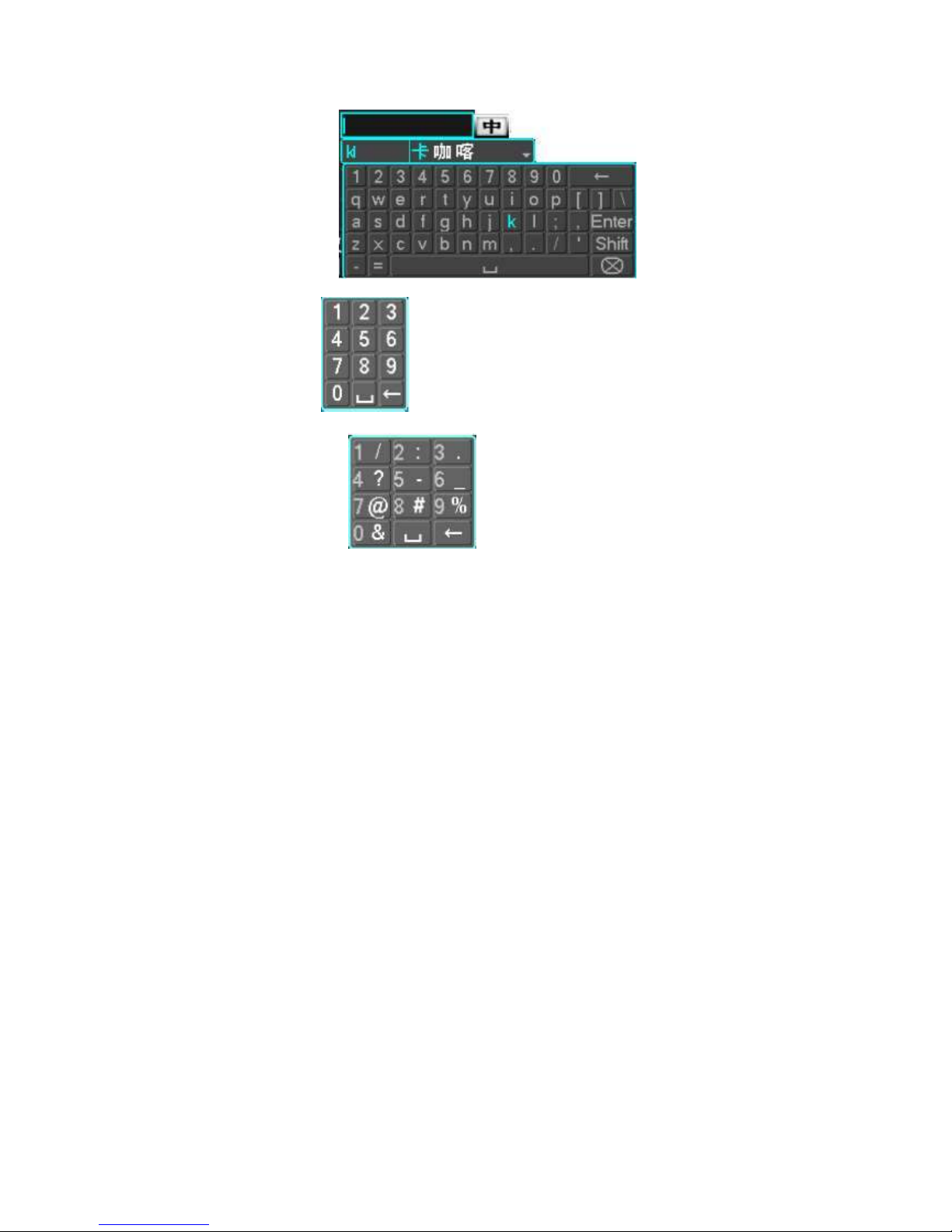
Chinese input interface:
Digital input interface:
Special symbols Interface:
3.7 Boot/Shutdown
3.7.1 Boot
DVR is correctly installed and plugged in, the power led is lit, video recorder will automatically
turn on. Show slightly different under different types of device power state , please refer to the
front panel section of this article.
DVR boot process will automatically detect the device hardware state, boot process takes about
20 seconds. Power-on complete devices after the buzzer was given a "beep" tone, and enter the
screen real-time video surveillance state, equipment operation or configuration can be at this
time. Please refer to 4.2 main menu introduction and subsequent introduction.
If the start-up time within the video to set the time, the system will automatically start a
scheduled recording function.
Note: Please use the DVR power supplied, you may not use other types of branded power supply
instead of the original power supply.
3.7.2 Shutdown
When Shutdown, direct to Unplug the power. or
Into the "main menu" - > "Close System" - > select "Shutdown”
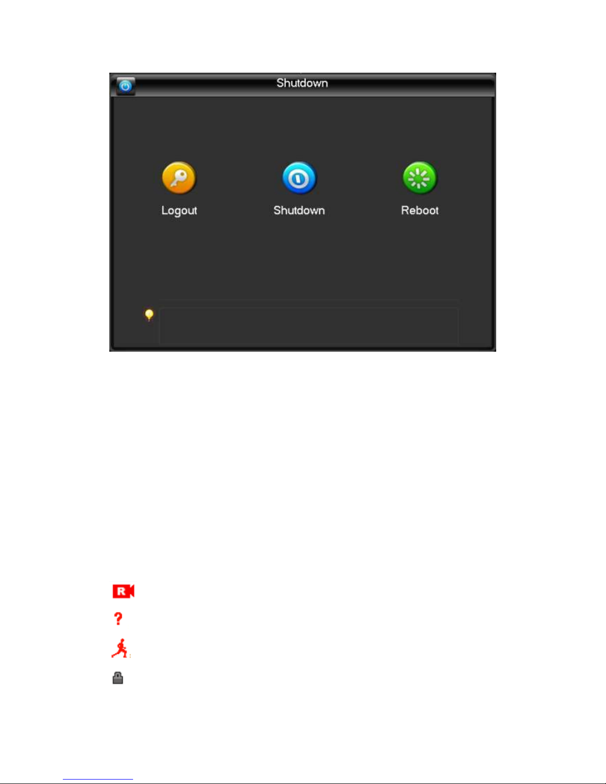
Note: replace the hard disk operation should be off the device and disconnect the power before
proceeding.
3.7.3 Power recovery
When the video recorder video work under the State, system power supply has been cut off or
been forced to shut down, after you reconnect the power, VCRs are automatically saved before
the power of video, and automatic restoration of power of state continue to work.
3.8 Screen icon
3.8.1 Status Icons
:This flag is displayed on the channel screen monitor channel video.
:Channel video loss occurs, the channel screen display this flag.
:Dynamic detection occurs, the channel screen display this flag.
:The channel is monitoring the locked state, this flag is displayed on the channel
screen.
: Allows the screen to switch polling.
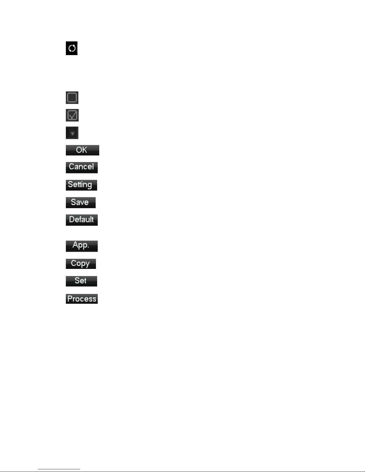
3.8.2 Operator Logos
:Enable box unchecked.
:Enabled box is checked state.
:Transferred out of the drop-down menu
:Determined to modify the settings / menu to enter
:Set / cancel to cancel the change to enter the menu.
: To set the parameters.
:Save the current set of parameters.
:Default factory settings, modify parameters, click on the button to return to
the last set of parameters.
:The current set of parameters is applied to the system.
:The current set of parameters are copied to the other channel.
:Enter the parameter configuration menu.
:Selection and configuration of the alarm, the processing operation of the
video detection trigger.
3.9 Real-time browser
Devices start correctly after entering the monitor screen in real time, each screen superimposed on the
date, time, channel name, the bottom of the screen there is a line for each channel of video and alarm
status icon. Also accessible through the front panel, the remote control or the right and left mouse button
double-click the screen switch operation.
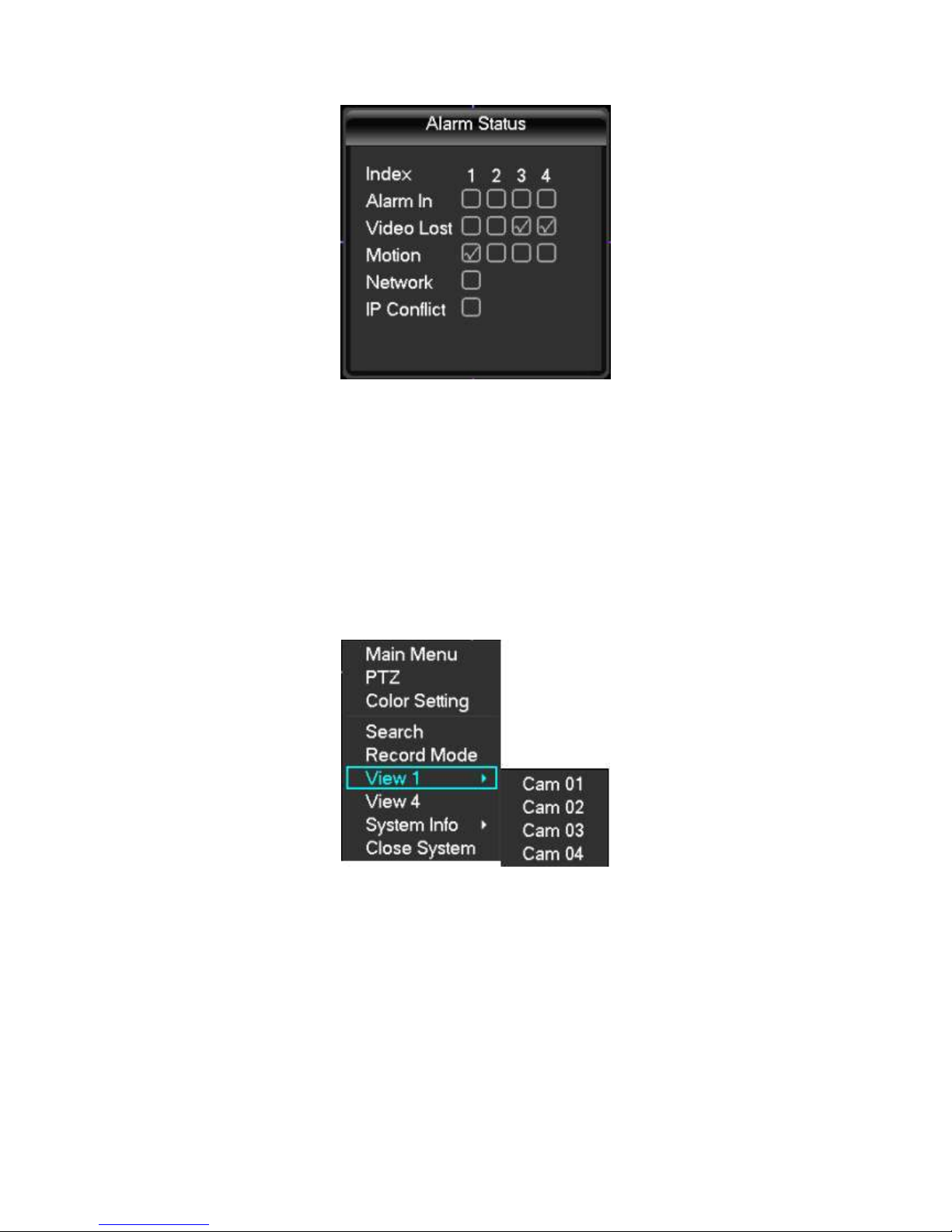
If you set the external alarm system, video loss, occlusion detection, dynamic, IP conflict detection,
network cable connection screen, when the alarm occurs, under real-time monitoring screen will pop up
prompting interface, as shown in figure:
4 Operations Guide
4.1 Right-click menu
Boot, after entering the viewing interface in real time, click the right mouse button, a pop-up
action menu;
4.1.1 Screen switching
4 channels, you can watch channels as needed, single-screen, Quad-screen, screen and 16 display
adjustment
4.1.2 PTZ control
DVR's "peripherals management" "PTZ configure" PTZ Protocol, baud rate, address and other
parameters set, click on the "PTZ control", you can control the PTZ, details see 6.4 PTZ functions.
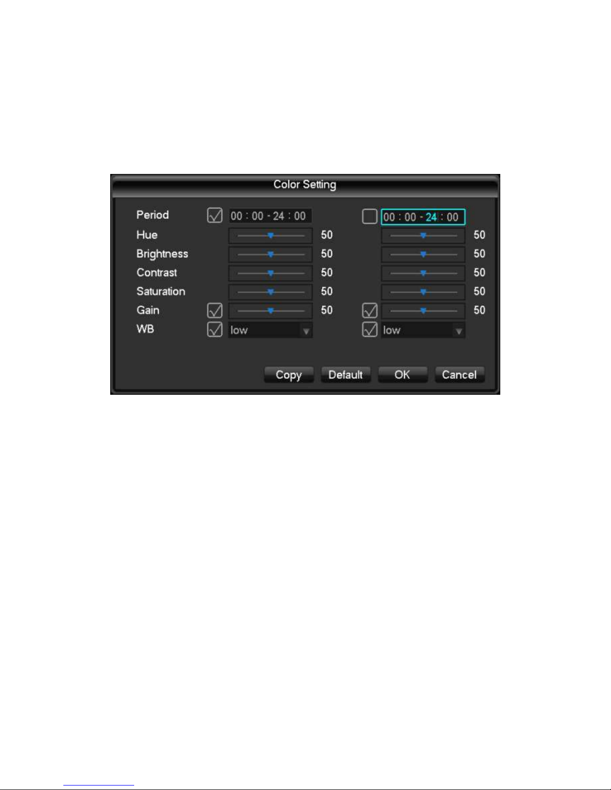
4.1.3 Image Color
Adjust the specified screen (single screen) image color hue, brightness, contrast, saturation, gain,
and white-level parameters, set two time periods, according to local environment different from
the brightness of the day and night, a separate regulation, after the time period set, the device
will automatically switch, makes pictures best video quality, as shown in figure
Time period: set the two one-hour segments, according to the ambient light of day and night,
after setting, the device will automatically switch according to the configuration of the time
period. Select the enable box to activate the functionality you want.
Hue: according to the color cast of the image, can be adjusted.
Brightness: V isual bright images, depending on the environment, reduce brightness or increase
the brightness of the image, to make the image clearer.
Contrast ratio: proportional control image black and white, the ratio the larger, image brighter, on
the contrary, the image gray.
Saturation: purity of image color, saturation, the ratio the larger, image more color.
Gain: the image signal amplification, improving signal quality.
White level: changing the white reference level value, and to improve the brightness of the
image displayed.
Note: the device supports the functionality of the different models are slightly different.
4.1.4 Video inquiry
4.1.5 Manual recording
Tip: manual recording operation requires the user to have a "video" operating authority.
Under real-time monitoring screen, click the right mouse button, click on the "manual recording",
or press "video" keys to go directly to the manual recording interface.
[Manually] With highest priority, regardless of what each channel in status, do the "manual"
button, the corresponding channel all ordinary video.
[Auto] V ideo by the video settings in the settings (normal, dynamic detection and alarm) the
video type video.
[Close] All channels stop recording.
To change the state of a channel of videos, first check the video channel is selected, or in select
State (non-select status indicates that the channel is not in the video status parameters select the
status indicates that the channel is in the video). And then use the mouse to click, or use the left
or right arrow keys to move the active box to the channel, then use the up or down arrow keys or
the numeric keys, switch the channel video.
Note: Select Enable can also change the video status of all channels.
4.1.6 Alarm output
4.1.7 Main menu
Click on the "main menu", users enter a user name and password in the box, click "OK" to enter
the system menu.
The factory default users are as follows:
Administrator user admin
Password 123456
Ordinary users User
Hide User Default
Note: password security measures: wrong password entered incorrectly 3 times device will beep
after alarm, 5 times your account will be locked, and account lockout after 30 minutes
automatically recover, for security reasons, please timely change the factory default password.
Adding user groups, users, and modify the users see 4.4.5 of the user management, mouse
operation, click on the "123" button to switch input method.
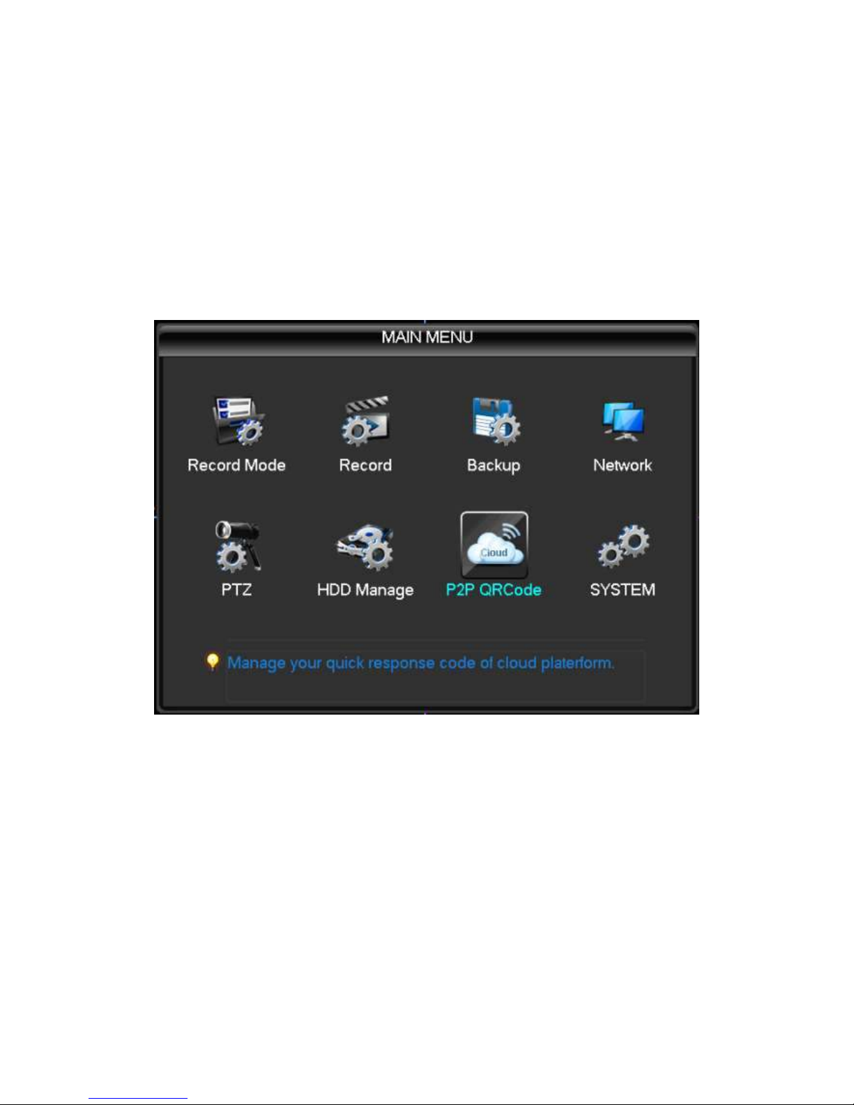
4.2 Main menu introduction
System main menu, main video control, video configuration, video backup cloud configuration,
hard disk, network configuration, configuring the alarm configuration and system settings.
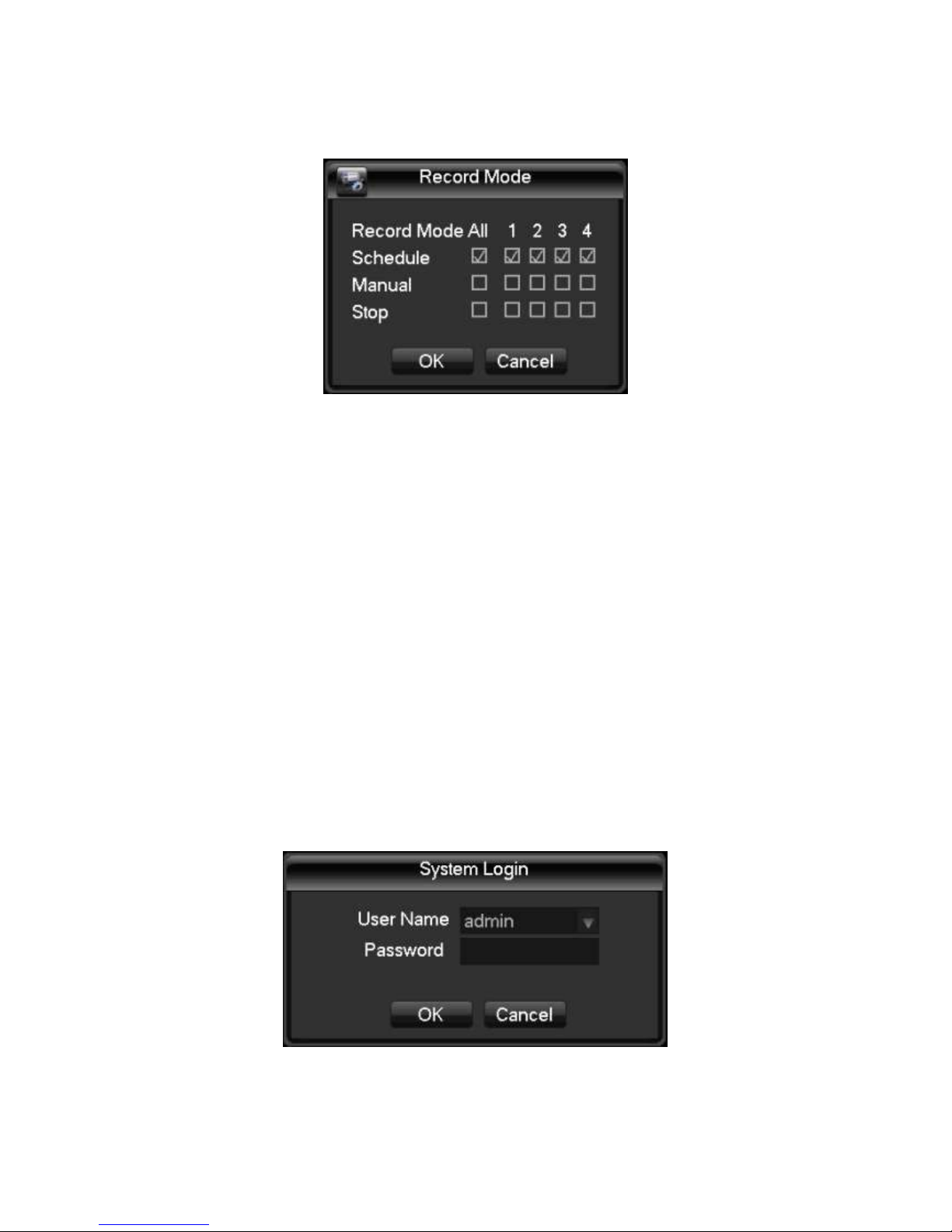
[Recording control] recording modes including automatic, manual, 3 modes on and off.
[Video configuration] set up video information, including recording basic information and
recording plans.
[Video backing up] the use of peripheral equipment for video backup.
[Network configuration] setting various parameters associated with the network.
[PTZ configuration] parameters of the pan.
[Disk management] information on managing hard disks.
[P2P QRCode] View cloud service connection status, see the serial number, download the mobile
client software.
[System settings] setting system, user and output configuration.4.3 Video queries

4.3 Video queries
Under real-time monitoring screen, click the right mouse button, click on the [video query], or through the
main menu to enter the video playback interface; Video query interfaces are described below:
Number 1 Calendar Click on the calendar icon will display a user video recording (Green fill indicates
that on that day, video, no fill that day without video), and then click on the date for which you want to
view, the file list will be automatically updated to the file list for the day
Number 2 Time select Select video query start time; click on the play button, select all channel
playback from that point.
Number 3 Playback controls Control video playback, enabling pause / play, rewind, stop, rewind, fast
release, the last frame, next frame pause state.
Number 4 Query video type selection Select the desired query type of video, including: all, all
external alarm, motion detection, alarm recording.
Number 5 Query channel selection Select the desired query type of video, including: full, alert,
dynamic testing, all of external alarm recording.
Number 6 Playback controls Select full screen, start / end clip, clip file backup, playback of video
control, display the playback status.
Number 7 Inquiry Select the end time after query, query channel, click on the query will display the
query results in the video list.
Number 8 Backup In file list box in the select user needs backup of file, in list box in the playing hook
can check (can in two a channel while select needs backup of file), again click Backup button, appears
backup operation menu, click Backup button to, user also can in backup operation menu in the canceled
don't want to backup of file, in to canceled of file list box before canceled hook (single channel displayed

list number for 128)
Number 9 Video list Display the query results in the video to the video list box displays a list of. 128
query time lists displayed on the screen of video files, you can press the up or down keys to view video
files, or drag the mouse wheel up or down to view video files. Select the files you want, press ENTER or
double click the left mouse button to start playing the video file. File type: R-normal videos a-external
alarm recording; M-dynamic detection of video.
Number 10 Channel queries Can select the channel you want to playback for video playback.
Playback control operation buttons are described below:
Fast forward video playback Playback mode, press the key, you can perform a wide range of fast
speed loop switches, fast forward; also serves as a slow reverse switch keys key
Video back to slow down to put Playback mode, press the key, you can perform a wide range of
slow speed cycle, slower also can be used as fast forward reverse switch button
Play / Pause Slow-motion playing, press the key, you can play / pause cycle switch.
Rewind Normal when playing a video file, click with the left mouse button rewind the
playback control panel buttons ' left ' rewind the video file, reply and click the rewind button "left" pause
rewind video file and (rewind, or when a single frame of video playback normal playback press the play
key to enter)
Manual single-frame video playback Normal playback video file is paused, the user presses XXX
single frame of video playback.
Note: 1player playback control panel displays the files to broadcast information such as speed,
channels, timing, playback progress.
2 rewind function and playback speed associated with the product version, please tip on the
player Panel shall prevail.
4.4 System Settings
Enter the system menu via the main menu interface, the menu system configuration, user
management, output mode, restore the default, auto maintenance and upgrade system.
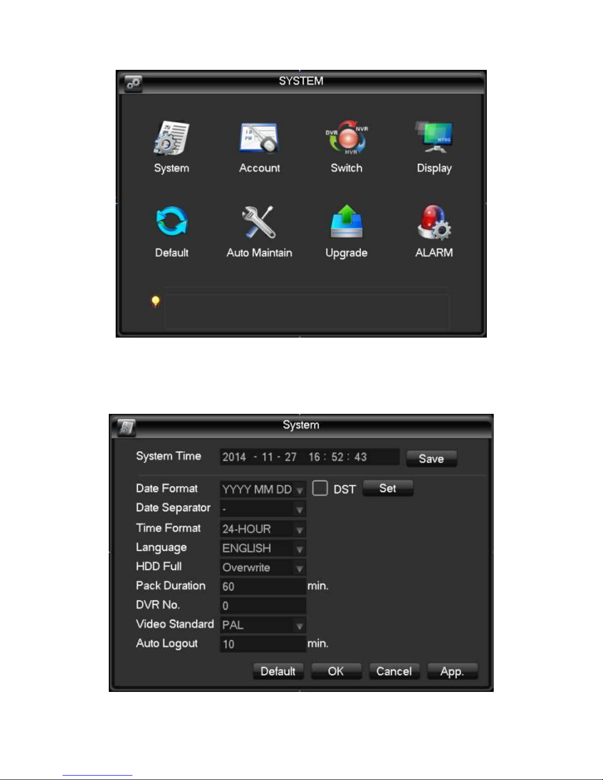
4.4.1 System configuration
Configure under the Manage menu in system configuration page:
[System time] Change the DVR system time Note: after you change the system time need to click Save

after key save individual system time.
[Date format] Select the date display format.
[Daylight saving time] Daylight saving time check box is checked, and then click on the settings button,
set the start and end of daylight time.
[Date] as the date format separator.
[Time format] includes 24-hour and 12-hour.
[Language choice] Switches the system menu language (different models have different language
options).
[When the hard disk is full] you can choose to either stop or cover. Stop recording conditions are: current
working disk is overwritten, or write my current working disk full, and the next non-empty hard disk, it will
stop recording; overriding condition is: write my current working disk full, and the next hard disk is not
empty, it loops over the first video file.
[Length of video] You can set the length of each video files, the default is 60 minutes, a maximum of 120
minutes.
[This number] is used more than a remote control or control panel remote control DVR, only when I press
the add key on the remote control and enter the remote address and have the same address with a
corresponding native DVR number for remote control operation.
[Video mode] select the video standard, PAL/NTSC (must match the camera system).
[Menu] menu ahead of time 0-60, 0 can be set to not set the standby time, if you set the time, after the
idle during this time, the system automatically logs off the current logged on user, users to action menu
you need to log in again.
4.4.2 User Management
User management basic notes:
The following user names and user group names, consisting of various characters and
lengths up to 6 bytes, string invalid leading or trailing spaces. Legal characters: letters, numbers,
underscore, minus sign, and do not allow the use of other characters.
No limit on the number of users and groups, user groups based on user-defined add or
remove groups: factory settings include group use\admin level, users can set their own groups
and users in the group can be specified in any of the set of permissions.
User group and user level approach management group names cannot be repeated, the user
name cannot be duplicated, each user must belong to a group, a user can belong to only one
group.
User management interface as shown in the figure.
 Loading...