

Page 1

POC-200 Series User’s Manual
Copyright © 2014 Neousys Technology Inc. All Right Reserved. Page 1 of 78
Neous
ys Technology Inc.
POC-200 Series
Ultra-compact Atom™ Bay Trail-I
Fanle
ss Embedded Controller with PoE and USB 3.0
User’s Manual
Rev. A1.1
Publi
shed Sep 24th, 2014
Page 2

POC-200 Series User’s Manual
Copyright © 2014 Neousys Technology Inc. All Right Reserved. Page 2 of 78
Date D
escription Version
2014/09/24 Modify 5V TTL GPIO Pin Define, Page 21,75 A1.1
Page 3

POC-200 Series User’s Manual
Copyright © 2014 Neousys Technology Inc. All Right Reserved. Page 3 of 78
Contents
Declai
mer ............................................................................................................................. 6
Declaration of Conformity ............................................................................................. 6
FCC ................................................................................................................... 6
CE ...................................................................................................................... 6
Copyright and Trademarks ........................................................................................... 6
Chapter 1 Introduction ......................................................................................................... 7
1.1 Overview ................................................................................................................. 7
1.2 Product Specification .............................................................................................. 8
1.2.1 Specification of POC-200 .......................................................................... 8
1.2.2 Specification of POC-210 .......................................................................... 9
1.2.3 Specification of POC-212 ........................................................................ 10
1.2.4 Specification of POC-222 ........................................................................ 12
Chapter 2 Getting Started .................................................................................................. 14
2.1 Unpacking your POC-200 ..................................................................................... 14
2.2 Front Panel I/O Functions ..................................................................................... 15
2.2.1 Power Button .......................................................................................... 15
2.2.2 Reset Button ........................................................................................... 16
2.2.3 LED Indicators ........................................................................................ 16
2.2.4 USB 3.0 Connectors ............................................................................... 17
2.2.5 Speaker-out Jack .................................................................................... 17
2.2.6 Gigabit Ethernet Ports ............................................................................. 18
2.2.7 IEEE 802.3at PoE PSE (POC-200 Only) ................................................ 19
2.2.8 DVI-I Connector ...................................................................................... 19
2.2.9 DIO Connector ........................................................................................ 20
2.2.9.1 Isolated DIO on POC-200 ................................................................. 20
2.2.9.2 5V TTL GPIO on POC-210/POC-212/POC-222 ............................... 22
2.3 Back Panel I/O Functions ..................................................................................... 24
2.3.1 USB3.0 Connectors ................................................................................ 24
2.3.2 USB2.0 Connectors ................................................................................ 25
2.3.3 COM Ports on POC-212/222 .................................................................. 25
2.3.4 COM Ports on POC-200/210 .................................................................. 26
2.3.5 2-Pin Terminal Block for DC Input ........................................................... 27
2.4 Internal I/O Functions ........................................................................................... 29
2.4.1 Remote On/Off Control ........................................................................... 29
2.4.2 Mini PCI Express Connector and SIM Socket ......................................... 30
2.4.3 DDR3L SODIMM Socket ......................................................................... 30
2.4.4 SATA Connector ..................................................................................... 31
2.5 POC-200/210 Mechanical Dimension ................................................................... 32
Page 4

POC-200 Series User’s Manual
Copyright © 2014 Neousys Technology Inc. All Right Reserved. Page 4 of 78
2.5.1 Top View ................................................................................................. 32
2.5.2
Front View ............................................................................................... 33
2.5.3 Side View ................................................................................................ 33
2.5.4 Bottom View ............................................................................................ 34
2.6 POC-212/222 Mechanical Dimension ................................................................... 35
2.6.1 Top View ................................................................................................. 35
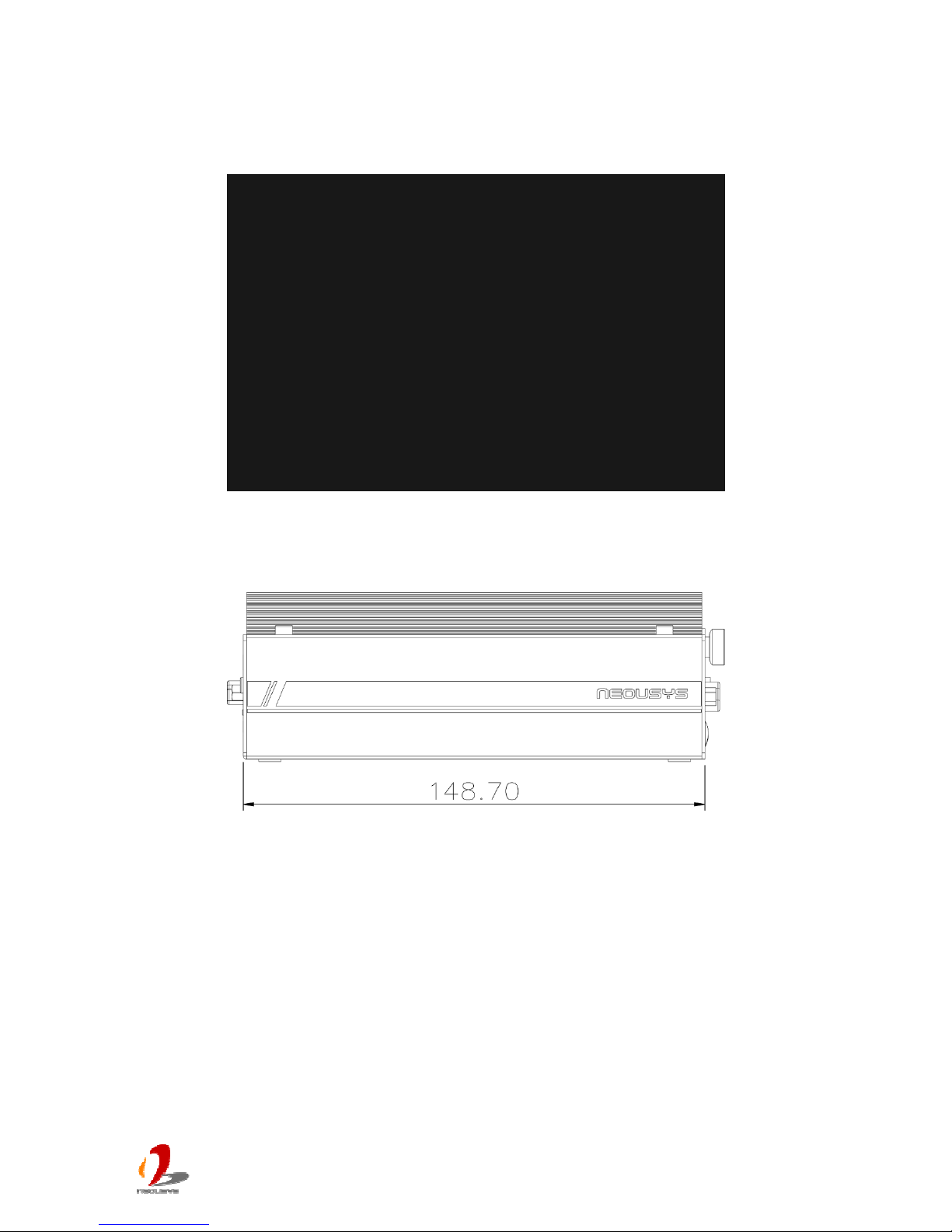
2.6.2 Front View ............................................................................................... 36
2.6.3 Side View ................................................................................................ 36
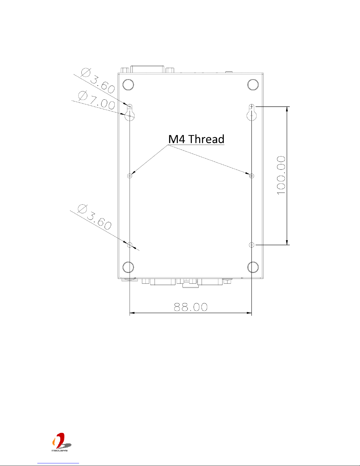
2.6.4 Bottom View ............................................................................................ 37
Chapter 3 Getting Start ...................................................................................................... 38
3.1 Dissemble your POC-200 Series .......................................................................... 38
3.1.1 Dissemble POC-200/210 ........................................................................ 38
3.1.2 Dissemble POC-212/222 ........................................................................ 39
3.2 Install a DDR3L SODIMM Module ........................................................................ 40
3.3 Install a 2.5” HDD/SSD ......................................................................................... 41
3.3.1 Install a 2.5” HDD/SSD on POC-200/210 ................................................ 41
3.3.2 Install a 2.5” HDD/SSD on POC-212/222 ................................................ 43
3.4 Install a Mini-PCIe Module .................................................................................... 44
3.4.1 Install a Mini-PCIe Module on POC-200/POC-210 ................................. 44
3.4.2 Install a Mini-PCIe Module on POC-212/222 .......................................... 46
3.5 Mount your POC-200 Series ................................................................................. 48
3.5.1 Suspend your POC-200 on the Wall ....................................................... 48
3.5.2 Mount your POC-200 Outside-in on a Surface ........................................ 49
3.5.3 Mount your POC-212/222 Inside-out on a Surface ................................. 50
3.5.4 Mount your POC-200 on the DIN Rail ..................................................... 51
3.6 Connect DC power to you POC-200 ..................................................................... 52
3.7 Power on your POC-200 ....................................................................................... 53
3.7.1 To Power on POC-200 Using the Power Button ..................................... 53
3.7.2 To Power on POC-200 Using an Latched Switch (AT-mode) ................. 54
3.7.3 To Power on POC-200 Using an Non-latched Switch (ATX-mode) ........ 55
3.7.4 To Power on POC-200 Using Wake-on-LAN Function............................ 56
Chapter 4 BIOS and Driver ................................................................................................ 59
4.1 BIOS Settings ....................................................................................................... 59
4.1.1 COM1 Operation Mode ........................................................................... 59
4.1.2 COM3 Operation Mode (POC-200/210 Only) ......................................... 60
4.1.3 Chipset SATA Mode................................................................................ 61
4.1.4 C-States and Max C-States .................................................................... 61
4.1.5 Wake-on-LAN Option .............................................................................. 62
4.1.6 Power On after Power Failure Option ..................................................... 63
4.1.7 Watchdog Timer for Booting ................................................................... 63
Page 5

POC-200 Series User’s Manual
Copyright © 2014 Neousys Technology Inc. All Right Reserved. Page 5 of 78
4.1.8 Select a Boot Device ............................................................................... 64
4.2 O
perating System Support ................................................................................... 66
4.3 Driver Installation .................................................................................................. 67
4.3.1 Install All Drivers Using “One-Click” Driver Installation ........................... 67
4.3.2 Install Drivers Manually ........................................................................... 68
Appendix A Using Watchdog Timer and DIO ..................................................................... 70
Install WDT and DIO Library ....................................................................................... 70
Using WDT Function ................................................................................................... 72
WDT Function Reference ................................................................................ 72
InitWDT ........................................................................................................ 72
SetWDT ........................................................................................................ 72
StartWDT ...................................................................................................... 73
ResetWDT .................................................................................................... 73
StopWDT ...................................................................................................... 74
Using DIO Function .................................................................................................... 74
Wiring for Isolated DIO (POC-200 Only) .......................................................... 74
Pin Definition for Isolated DIO (POC-200 Only) ............................................... 75
Pin Definition for 5V TTL GPIO (POC-210/212/222) ........................................ 76
DIO Function Reference .................................................................................. 76
InitDIO .......................................................................................................... 76
DIReadLine .................................................................................................. 77
DIReadPort ................................................................................................... 77
DOWriteLine ................................................................................................. 77
DOWritePort ................................................................................................. 78
Page 6

POC-200 Series User’s Manual
Copyright © 2014 Neousys Technology Inc. All Right Reserved. Page 6 of 78
Declaimer
This manual is intended to be used as a practical and informative guide only and is subject
to cha
nge without prior notice. It does not represent commitment from Neousys Technology
Inc. Neousys shall not be liable for direct, indirect, special, incidental, or consequential
damages arising out of the use of the product or documentation, nor for any infringements
upon the rights of third parties, which may result from such use.
Declaration of Conformity
FCC
This equipment has been tested and found to comply with the limits for a Class A digital
device
, pursuant to part 15 of the FCC Rules. These limits are designed to provide
reasonable protection against harmful interference when the equipment is operated in a
commercial environment. This equipment generates, uses, and can radiate radio frequency
energy and, if not installed and used in accordance with the instruction manual, may cause
harmful interference to radio communications. Operation of this equipment in a residential
area is likely to cause harmful interference in which case the user will be required to correct
the interference at his own expense.
CE
The product(s) described in this manual complies with all applicable European Union (CE)
direct
ives if it has a CE marking. For computer systems to remain CE compliant, only
CE-compliant parts may be used. Maintaining CE compliance also requires proper cable
and cabling techniques.
Copyright and Trademarks
This document contains proprietary information protected by copyright. All rights are
reserved. No part of this document may be reproduced by any mechanical, electronic, or
other means in any form without prior written permission of the manufacturer.
Company/product names mentioned herein are used for identification purposes only and
are trademarks and/or registered trademarks of their respective companies.
Page 7
POC-200 Series User’s Manual
Copyright © 2014 Neousys Technology Inc. All Right Reserved. Page 7 of 78
Chapter 1 Introduction
1.1 Overview
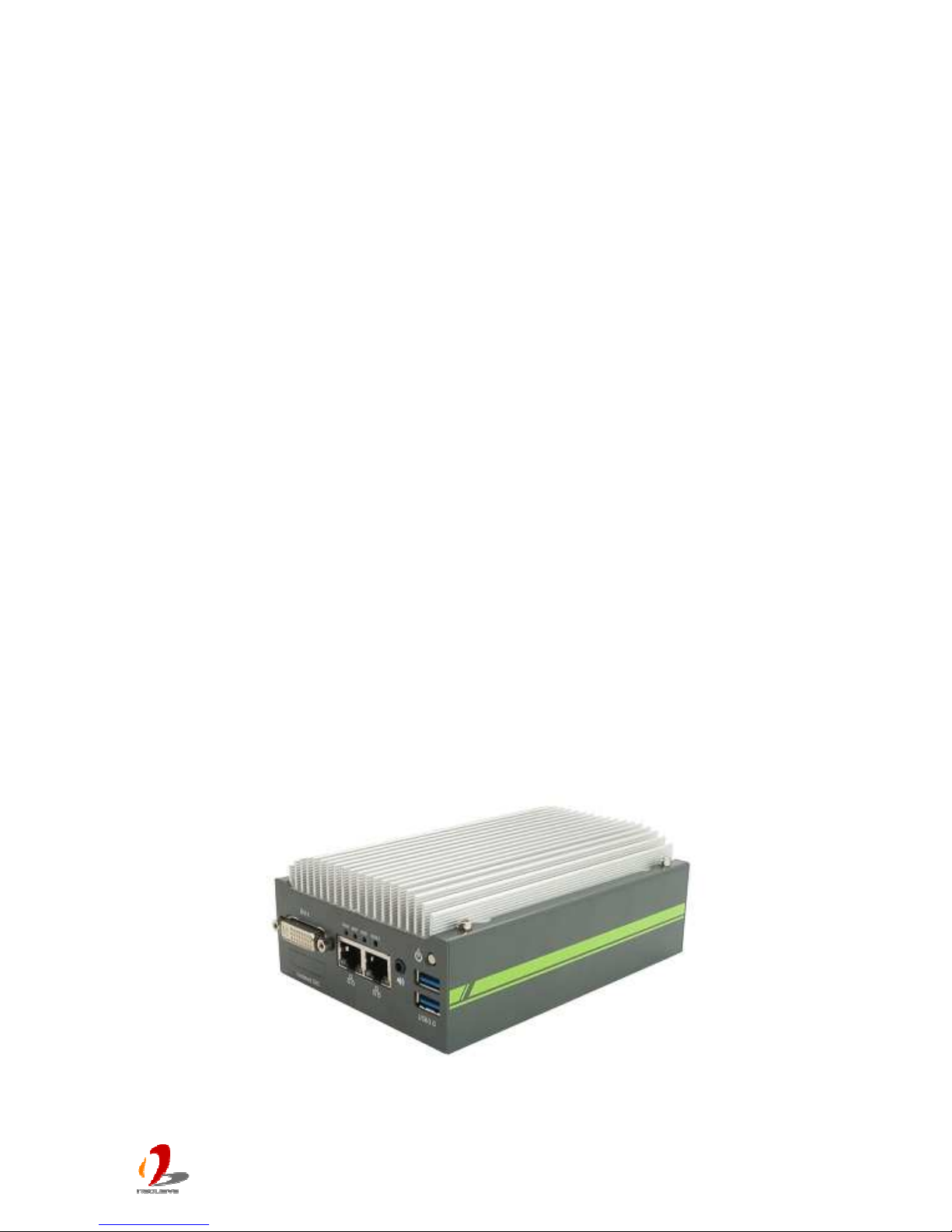
POC-200 series is a breakthrough of Neousys’ ultra-compact controller series. Inheriting
the c
oncept of favorable POC-100, POC-200 series further incorporates greater computing
power and more versatile functions in its 3.5” HDD footprint.
The new Intel® Atom™ Bay Trail-I platform brings a leaping for both arithmetic and
graphics performance. With Atom™ E3845 quad-core processor, POC-200 can deliver
more than 200% performance over previous D525/D2550 platform. It also feature
comprehensive I/O interfaces to make use of the advance of computing power. Two Gigabit
Ethernet and three USB 3.0 ports are integrated so you can connect GigE/USB3 cameras
for vision applications. Its IEEE 802.3at PoE option is capable to supply 25.5W each port to
power you IP camera for surveillance applications. POC-200 series also features up to four
COM ports and digital I/O for general-purpose industrial applications.
Size is another attractive feature of POC-200. Its 6”x4” footprint makes installation of
POC-200 extremely easy. And its -30°C to 70°C operating temperature eliminates the
restriction for deployment environment. Neousys provides derivative models with different
CPU and I/O configuration so you can always find a fit POC-200 for your application.
Page 8

POC-200 Series User’s Manual
Copyright © 2014 Neousys Technology Inc. All Right Reserved. Page 8 of 78
1.2 Product Specification
1.2.1 Specification of POC-200
System Core
Processor Intel® Atom™ E3845 1.91 GHz quad-core processor
Graphics Integrated Intel® HD Graphics
Memory 1x SODIMM socket for DDR3L-1333, up to 8GB
Panel I/O Interface
Ethernet 2x Gigabit Ethernet ports by Intel® I210 GbE controller
PoE
IEEE 802.3at PoE PSE (25.5W each GbE port))
Video Port
1x DVI-I connector for both analog RGB and DVI/HDMI outputs, supporting up to
2560 x 1600 resolution
Serial Port
2x software-programmable RS-232/422/485 (COM1 & COM3)
2x RS-232 (COM2 & COM4)
USB
1x USB 3.0 port via native USB3 controller
2x USB 3.0 ports via Renasas uPD720202 USB3 host controller
1x USB 2.0 port
Audio 1x Speaker-out
DIO 4-CH isolated DI + 4-CH isolated DO
Internal I/O Interface
Mini-PCIe 1x mini PCI Express slot with USIM socket
Storage Interface
SATA HDD 1x internal SATA port for 2.5” HDD/SSD
Power Supply
DC Input Built-in 8~35 VDC DC input
Input Connector 2-pin pluggable terminal block for DC input
Power Consumption
Typical: 7.68W (0.32A@24V)
Full-loading: 13.44W (0.56A@24V)*
Mechanical
Dimension 149mm (W) x 105 mm (H) x 58 mm (D)
Weight 1.1 kg (with one 2.5” SATA HDD)
Mounting Wall-mount (Standard)
DIN-rail mount (Optional)
Environmental
Operating
Temperature
-30°C ~ 70°C with SSD, 100% CPU loading **/***
-10°C ~ 60°C with HDD, 100% CPU loading **/***
Page 9

POC-200 Series User’s Manual
Copyright © 2014 Neousys Technology Inc. All Right Reserved. Page 9 of 78
Storage
Tempe
rature
-40°C ~85°C
Humidity 10%~90% , non-condensing
Vibration Operating, 5 Grms, 5-500 Hz, 3 Axes (w/ SSD, w/o add-on card, according to
Shock
Operating, 50 Grms, Half-sine 11 ms Duration (w/ SSD, w/o add-on card, according
to IEC60068-2-27)
EMC CE/FCC Class A, according to EN 55022 & EN 55024
* Full-loading power consumption is measured with 2GB DDR3 memory and one 2.5” SATA HDD installed under the
following conditions:
- 100% loading for Atom E3845 CPU
- 100% loading for 3D graphics
- 100% loading for GbE port
** The 100% CPU loading is applied using Passmark® BurnInTest™ v7.0. For detail testing criteria, please contact
Neousys Technology
*** For sub-zero operating temperature, wide-temperature DDR3-L and wide-temperature HDD/SSD are required.
1.2.2 Specification of POC-210
System Core
Processor Intel® Atom™ E3845 1.91 GHz quad-core processor
Graphics Integrated Intel® HD Graphics
Memory 1x SODIMM socket for DDR3L-1333, up to 8GB
Panel I/O Interface
Ethernet 2x Gigabit Ethernet ports by Intel® I210 GbE controller
PoE
N/A
Video Port
1x DVI-I connector for both analog RGB and DVI/HDMI outputs, supporting up to
2560 x 1600 resolution
Serial Port
2x software-programmable RS-232/422/485 (COM1 & COM3)
2x RS-232 (COM2 & COM4)
USB
1x USB 3.0 port via native USB3 controller
2x USB 3.0 ports via Renasas uPD720202 USB3 host controller
1x USB 2.0 port
Audio 1x Speaker-out
DIO 4-CH 5V TTL DI + 4-CH 5V TTL DO
Internal I/O Interface
Mini-PCIe 1x mini PCI Express slot with USIM socket
Storage Interface
SATA HDD 1x internal SATA port for 2.5” HDD/SSD
Power Supply
DC Input Built-in 8~35 VDC DC input
Page 10

POC-200 Series User’s Manual
Copyright © 2014 Neousys Technology Inc. All Right Reserved. Page 10 of 78
Input Connector 2-pin pluggable terminal block for DC input
Power Consumption
Typical: 7.68W (0.32A@24V)
Full-loading: 13.44W (0.56A@24V)*
Mechanical
Dimension 149mm (W) x 105 mm (H) x 58 mm (D)
Weight 1.1 kg (with one 2.5” SATA HDD)
Mounting Wall-mount (Standard)
DIN-rail mount (Optional)
Environmental
Operating
Temperature
-30°C ~ 70°C with SSD, 100% CPU loading **/***
-10°C ~ 60°C with HDD, 100% CPU loading **/***
Storage
Temperature
-40°C ~85°C
Humidity 10%~90% , non-condensing
Vibration Operating, 5 Grms, 5-500 Hz, 3 Axes (w/ SSD, w/o add-on card, according to
Shock
Operating, 50 Grms, Half-sine 11 ms Duration (w/ SSD, w/o add-on card, according
to IEC60068-2-27)
EMC CE/FCC Class A, according to EN 55022 & EN 55024
* Full-loading power consumption is measured with 2GB DDR3 memory and one 2.5” SATA HDD installed under the
following conditions:
- 100% loading for Atom E3845 CPU
- 100% loading for 3D graphics
- 100% loading for GbE port
** The 100% CPU loading is applied using Passmark® BurnInTest™ v7.0. For detail testing criteria, please contact
Neousys Technology
*** For sub-zero operating temperature, wide-temperature DDR3-L and wide-temperature HDD/SSD are required.
1.2.3 Specification of POC-212
System Core
Processor Intel® Atom™ E3845 1.91 GHz quad-core processor
Graphics Integrated Intel® HD Graphics
Memory 1x SODIMM socket for DDR3L-1333, up to 8GB
Panel I/O Interface
Ethernet 2x Gigabit Ethernet ports by Intel® I210 GbE controller
PoE
N/A
Video Port
1x DVI-I connector for both analog RGB and DVI/HDMI outputs, supporting up to
2560 x 1600 resolution
Serial Port
1x software-programmable RS-232/422/485 (COM1)
1x RS-232 (COM2)
Page 11

POC-200 Series User’s Manual
Copyright © 2014 Neousys Technology Inc. All Right Reserved. Page 11 of 78
USB
1x US
B 3.0 port via native USB3 controller
2x USB 3.0 ports via Renasas uPD720202 USB3 host controller
1x USB 2.0 port
Audio 1x Speaker-out
DIO 4-CH 5V TTL DI + 4-CH 5V TTL DO
Internal I/O Interface
Mini-PCIe 1x mini PCI Express slot with USIM socket
Storage Interface
SATA HDD 1x internal SATA port for 2.5” HDD/SSD
Power Supply
DC Input Built-in 8~35 VDC DC input
Input Connector 2-pin pluggable terminal block for DC input
Power Consumption
Typical: 7.68W (0.32A@24V)
Full-loading: 13.44W (0.56A@24V)*
Mechanical
Dimension 149mm (W) x 105 mm (H) x 54 mm (D)
Weight 1.1 kg (with one 2.5” SATA HDD)
Mounting Wall-mount (Standard)
DIN-rail mount (Optional)
Environmental
Operating
Temperature
-30°C ~ 70°C with SSD, 100% CPU loading **/***
-10°C ~ 60°C with HDD, 100% CPU loading **/***
Storage
Temperature
-40°C ~85°C
Humidity 10%~90% , non-condensing
Vibration Operating, 5 Grms, 5-500 Hz, 3 Axes (w/ SSD, w/o add-on card, according to
Shock
Operating, 50 Grms, Half-sine 11 ms Duration (w/ SSD, w/o add-on card, according
to IEC60068-2-27)
EMC CE/FCC Class A, according to EN 55022 & EN 55024
* Full-loading power consumption is measured with 2GB DDR3 memory and one 2.5” SATA HDD installed under the
following conditions:
- 100% loading for Atom E3845 CPU
- 100% loading for 3D graphics
- 100% loading for GbE port
** The 100% CPU loading is applied using Passmark® BurnInTest™ v7.0. For detail testing criteria, please contact
Neousys Technology
*** For sub-zero operating temperature, wide-temperature DDR3-L and wide-temperature HDD/SSD are required.
Page 12

POC-200 Series User’s Manual
Copyright © 2014 Neousys Technology Inc. All Right Reserved. Page 12 of 78
1.2.4 Specification of POC-222
System Core
Processor Intel® Atom™ E3825 1.33 GHz dual-core processor
Graphics Integrated Intel® HD Graphics
Memory 1x SODIMM socket for DDR3L-1067, up to 4GB
Panel I/O Interface
Ethernet 2x Gigabit Ethernet ports by Intel® I210 GbE controller
PoE
N/A
Video Port
1x DVI-I connector for both analog RGB and DVI/HDMI outputs, supporting up to
2560 x 1600 resolution
Serial Port
1x software-programmable RS-232/422/485 (COM1)
1x RS-232 (COM2)
USB
1x USB 3.0 port via native USB3 controller
2x USB 3.0 ports via Renasas uPD720202 USB3 host controller
1x USB 2.0 port
Audio 1x Speaker-out
DIO 4-CH 5V TTL DI + 4-CH 5V TTL DO
Internal I/O Interface
Mini-PCIe 1x mini PCI Express slot with USIM socket
Storage Interface
SATA HDD 1x internal SATA port for 2.5” HDD/SSD
Power Supply
DC Input Built-in 8~35 VDC DC input
Input Connector 2-pin pluggable terminal block for DC input
Power Consumption
Typical: 7.27W (0.30A@24V)
Full-loading: 9.60W (0.40A@24V)*
Mechanical
Dimension 149mm (W) x 105 mm (H) x 54 mm (D)
Weight 1.1 kg (with one 2.5” SATA HDD)
Mounting Wall-mount (Standard)
DIN-rail mount (Optional)
Environmental
Operating
Temperature
-30°C ~ 70°C with SSD, 100% CPU loading **/***
-10°C ~ 60°C with HDD, 100% CPU loading **/***
Storage
Temperature
-40°C ~85°C
Humidity 10%~90% , non-condensing
Page 13

POC-200 Series User’s Manual
Copyright © 2014 Neousys Technology Inc. All Right Reserved. Page 13 of 78
Vibration Operating, 5 Grms, 5-500 Hz, 3 Axes (w/ SSD, w/o add-on card, according to
Shock
Operating, 50 Grms, Half-sine 11 ms Duration (w/ SSD, w/o add-on card, according
to IEC60068-2-27)
EMC CE/FCC Class A, according to EN 55022 & EN 55024
* Full-loading power consumption is measured with 2GB DDR3 memory and one 2.5” SATA HDD installed under the
following conditions:
- 100% loading for Atom E3845 CPU
- 100% loading for 3D graphics
- 100% loading for GbE port
** The 100% CPU loading is applied using Passmark® BurnInTest™ v7.0. For detail testing criteria, please contact
Neousys Technology
*** For sub-zero operating temperature, wide-temperature DDR3-L and wide-temperature HDD/SSD are required.
Page 14

POC-200 Series User’s Manual
Copyright © 2014 Neousys Technology Inc. All Right Reserved. Page 14 of 78
Chapter 2 Getting Started
2.1 Unpacking your POC-200
When you receive the package of POC-200 series, please check immediately if the
package
contains all the items listed in the following table. If any item is missing or
damaged, please contact your local dealer or Neousys Technology Inc. for further
assistance.
Item
Description Qty
1 POC-200/210/212/222 ultra-compact fanless controller
(According to the configuration you order, your POC-200 may contain
DDR3L module or SATA HDD. Please verify these items if necessary.)
1
2 Specialized DVI-to-VGA adapter for POC-200 1
3 2-pin pluggable terminal block 1
4 Neousys Drivers & Utilities DVD 1
5 Screw package 1
Page 15
POC-200 Series User’s Manual
Copyright © 2014 Neousys Technology Inc. All Right Reserved. Page 15 of 78
2.2 Front Panel I/O Functions
On POC-200 series, we design general-purpose I/O functions on the front panel so you can
easily
access them. In this section, we’ll illustrate each I/O function on the front panel.
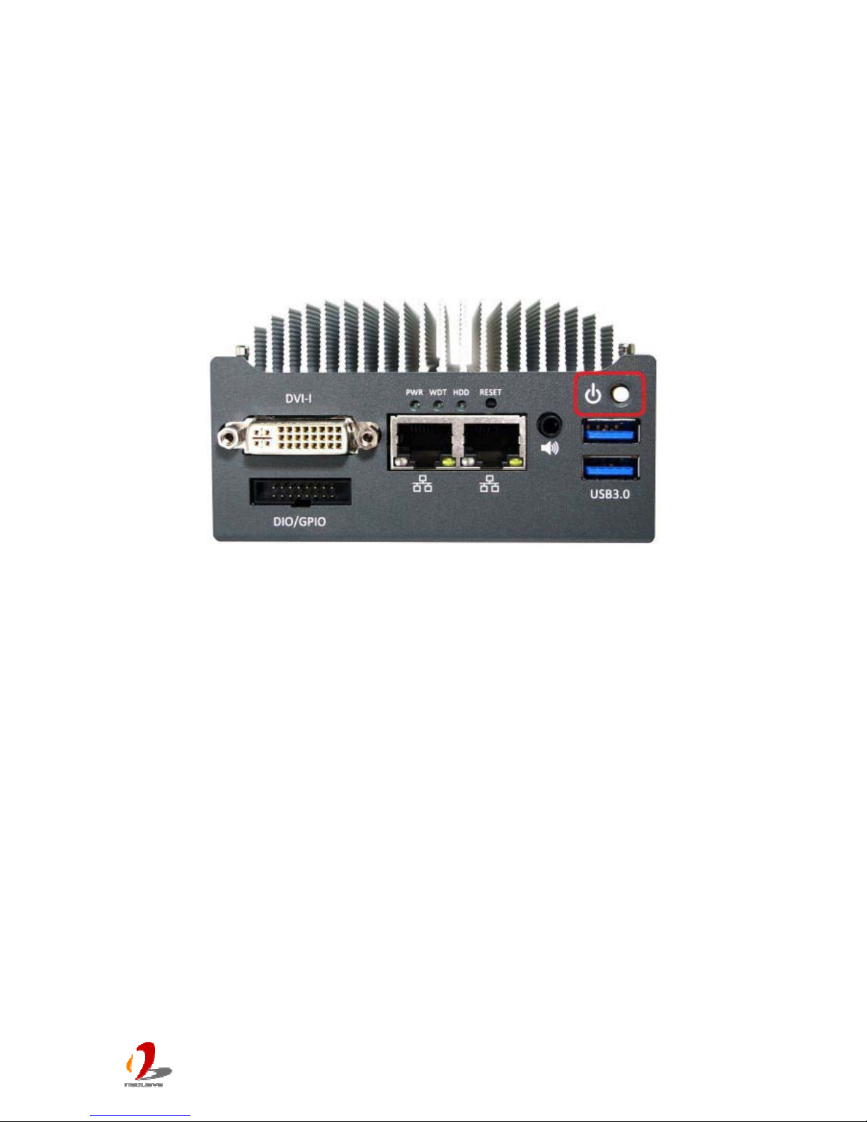
2.2.1 Power Button
The power button is a non-latched switch for ATX mode on/off operation. To turn on the
POC-200, press the power button and the PWR LED on the center-top side is lighted up.
To turn off the POC-200, you can either issue a shutdown command in OS, or just simply
press the power button. In case of system halts, you can press and hold the power button
for 5 seconds to compulsorily shut down the system. Please note that a 5 seconds interval
is kept by the system between two on/off operations (i.e. once turning off the system, you
shall wait for 5 seconds to initiate another power-on operation).
Page 16
POC-200 Series User’s Manual
Copyright © 2014 Neousys Technology Inc. All Right Reserved. Page 16 of 78
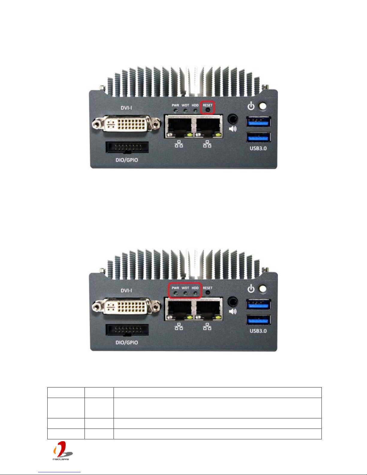
2.2.2 Reset Button
The reset button is used to manually reset the system in case of any abnormal condition.
To avoid unexpected operation, the reset button is hidden behind the front panel. You need
to use a pin-like object to push the reset button.
2.2.3 LED Indicators
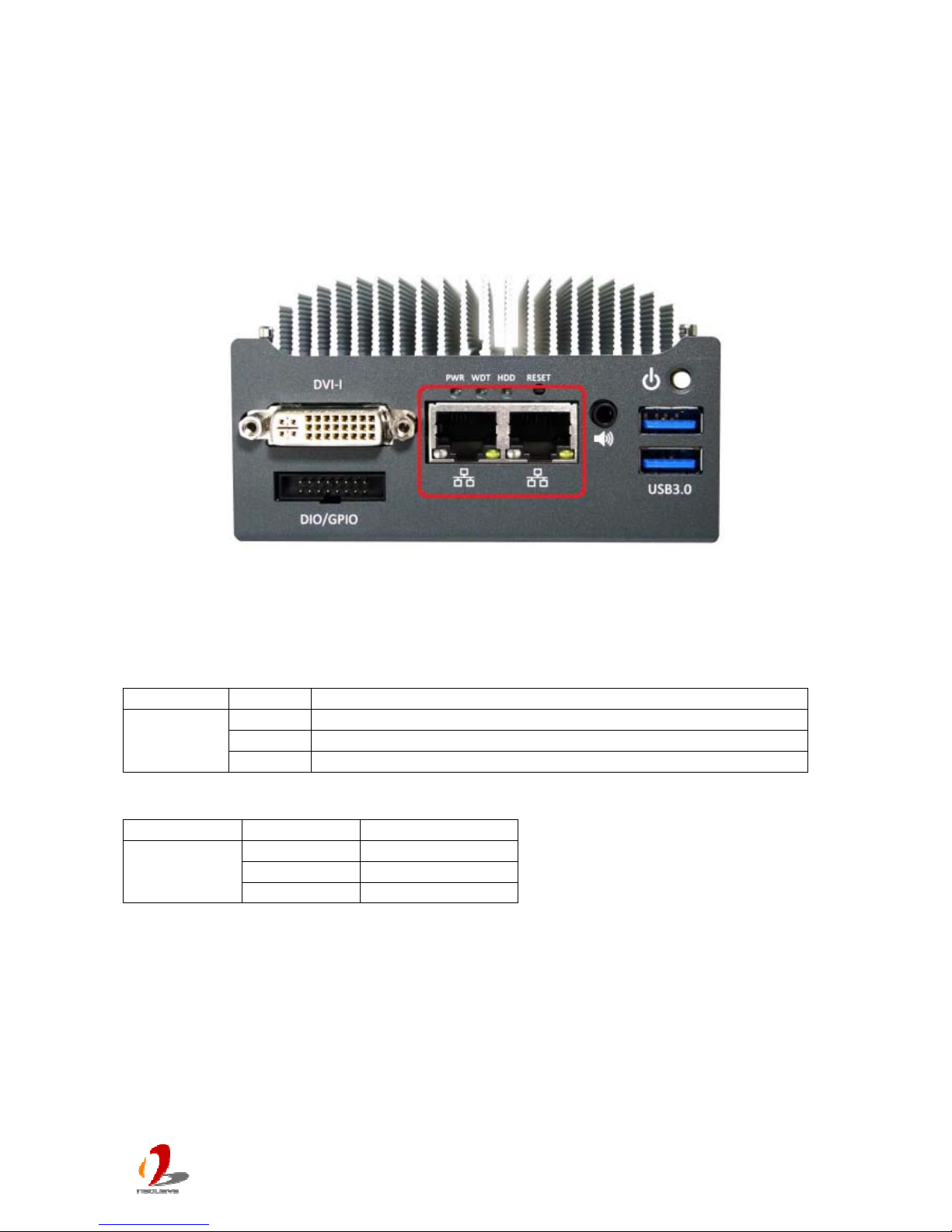
There are three LED indicators on the front panel: PWR, WDT and HDD. The descriptions
of these three LED are listed in the following table.
Indicator Color Description
PWR Green Power indictor, lighted-up when system is on, off when system is
off.
WDT Yellow Watchdog timer indicator, flashing when watchdog timer is started.
HDD Red Hard drive indicator, flashing when SATA hard drive is active.
Page 17
POC-200 Series User’s Manual
Copyright © 2014 Neousys Technology Inc. All Right Reserved. Page 17 of 78
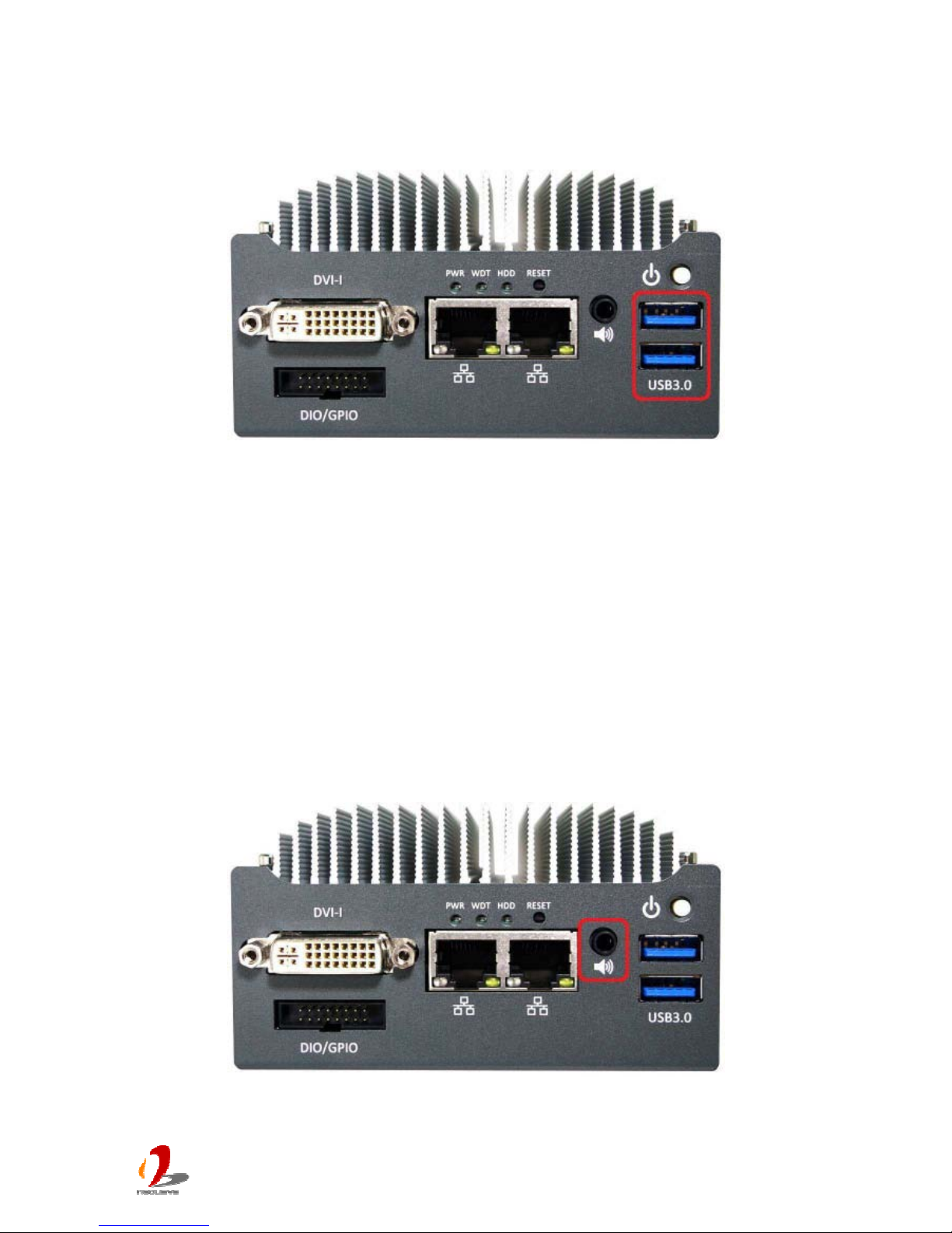
2.2.4 USB 3.0 Connectors
There are totally three USB 3.0 ports and one USB 2.0 port on POC-200 series. Two of
three USB 3.0 ports are located on the front panel. They are implemented via a Renasas
uPD720202 USB3 host controller. By BIOS default, these USB ports are operated in xHCI
(eXtensible Host Control Interface) mode and are compatible to USB 3.0, USB 2.0, USB
1.1 and USB 1.0 devices. Legacy USB support on these ports is provided only when “xHCI
Mode” option in BIOS is configured as “Smart Auto”.
To utilize USB 3.0 function in Windows, you need to install corresponding driver for
Renasas uPD720202 USB3.0 controller. Please refer to section 4.3 for information of driver
installation.
2.2.5 Speaker-out Jack
POC-200 series provides speaker-out function using Intel® High Definition Audio (built-in in
ICH8-
M) and Realtek ALC262 codec. An audio jack is located on the front panel. To utilize
Page 18
POC-200 Series User’s Manual
Copyright © 2014 Neousys Technology Inc. All Right Reserved. Page 18 of 78
the speaker-out function in Windows, you need to install corresponding drivers for both
Intel®
ICH8-M chipset and Realtek ALC262 codec. Please refer to section 4.3 for
information of driver installation.
2.2.6 Gigabit Ethernet Ports
POC-200 series offers two Gigabit Ethernet ports using Intel® I210 GbE controller. When
plugging in the Ethernet cable, you can tell the Ethernet status and speed from the LED
indicators on the RJ45 connector as following:
Active/Link LED
LED Color Status Description
Yellow Off Ethernet port is disconnected
On Ethernet port is connected and no data transmission
Flashing Ethernet port is connected and data is transmitting/receiving
Speed LED
LED Color Status Description
Green or
Orange
Off 10 Mbps
Green 100 Mbps
Orange 1000 Mbps
To utilize the GbE port in Windows, you need to install corresponding driver for Intel® I210
GbE controller. Please refer to 4.3 for information of driver installation.
Page 19
POC-200 Series User’s Manual
Copyright © 2014 Neousys Technology Inc. All Right Reserved. Page 19 of 78
2.2.7 IEEE 802.3at PoE PSE (POC-200 Only)
PoE, or Power over Ethernet, is a technology to supply electrical power along with data on
a standard CAT-5/CAT-6 Ethernet cable. Two Gigabit Ethernet ports on POC-200 support
IEEE 802.3at PoE PSE (Power Sourcing Equipment) function. Each PoE port can deliver
25.5 W of power to a PoE PD (Powered Device), such as a PoE IP camera or a PoE WIFI
AP. PoE defines a mechanism to automatically detect the device connected and determine
whether to dispatch power. This makes PoE port 100% compatible with traditional Ethernet
devices thus you can use these ports to connect PoE or non-PoE devices.
2.2.8 DVI-I Connector
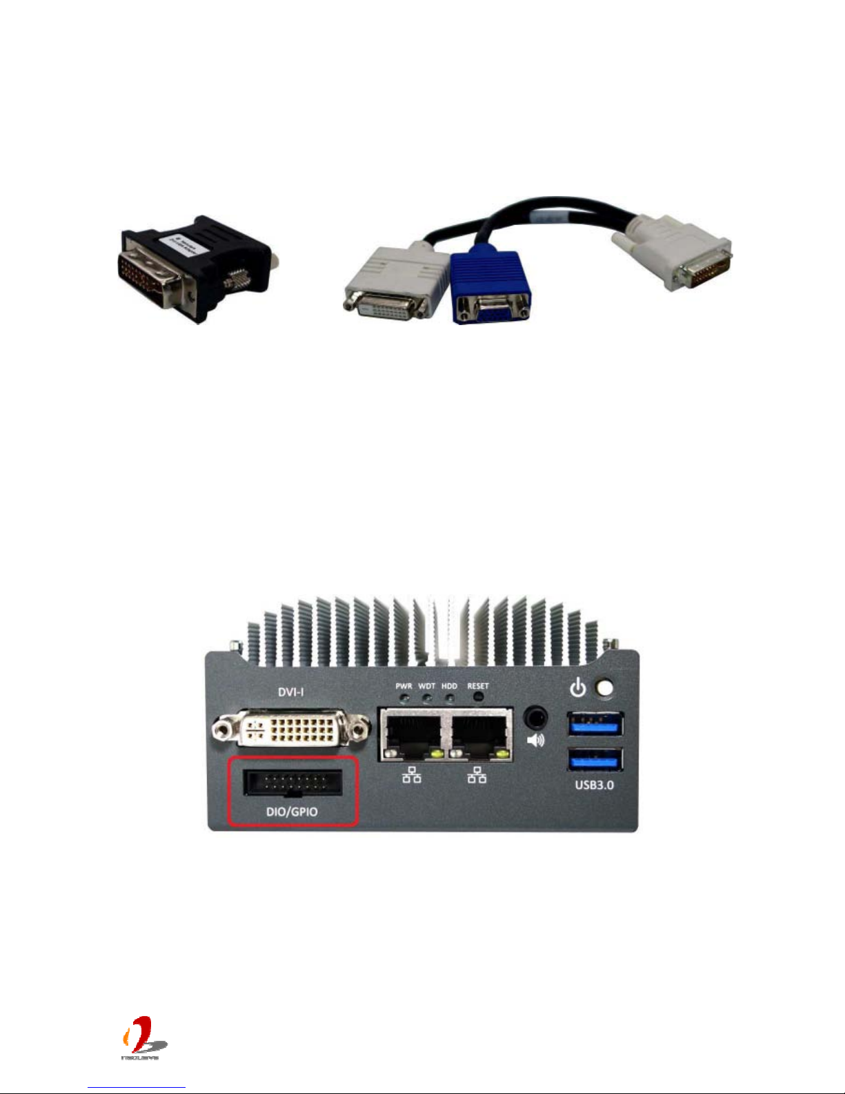
POC-200 series features a DVI-I connector on its front panel to output both VGA and
DVI/HDMI signals. The DVI/HDMI and VGA outputs are directly driven by integrated Intel
HD Graphics engine and support up to 2560 x 1600 resolution.
Page 20
POC-200 Series User’s Manual
Copyright © 2014 Neousys Technology Inc. All Right Reserved. Page 20 of 78
For VGA monitor, Neousys offers a specialized DVI-to-VGA adapter as an accessory
shippe
d with POC-200 series. This adapter supports VGA DDC signals and thus eliminates
compatibility issues with VGA monitors. Or you can use a DVI-I to VGA+DVI-D Y-cable to
support two independent display outputs.
DVI-to-VGA Adapter DVI-I to VGA+DVI-D Y-Cable
To have best graphics performance in Windows, you need to install corresponding graphics
driver. Please refer to section 4.3 for information of driver installation.
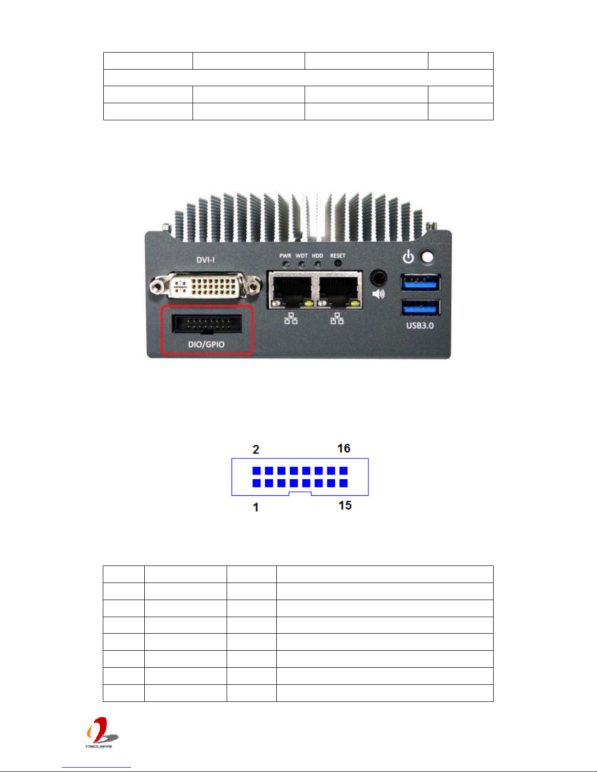
2.2.9 DIO Connector
2.2.9.1 Isolated DIO on POC-200
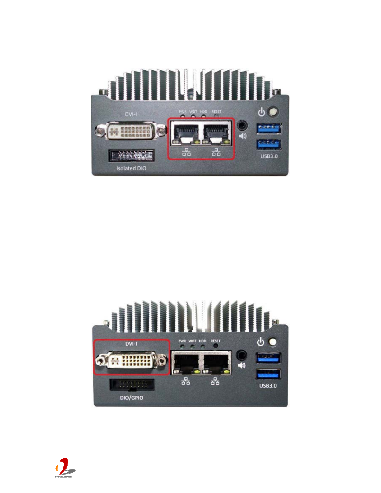
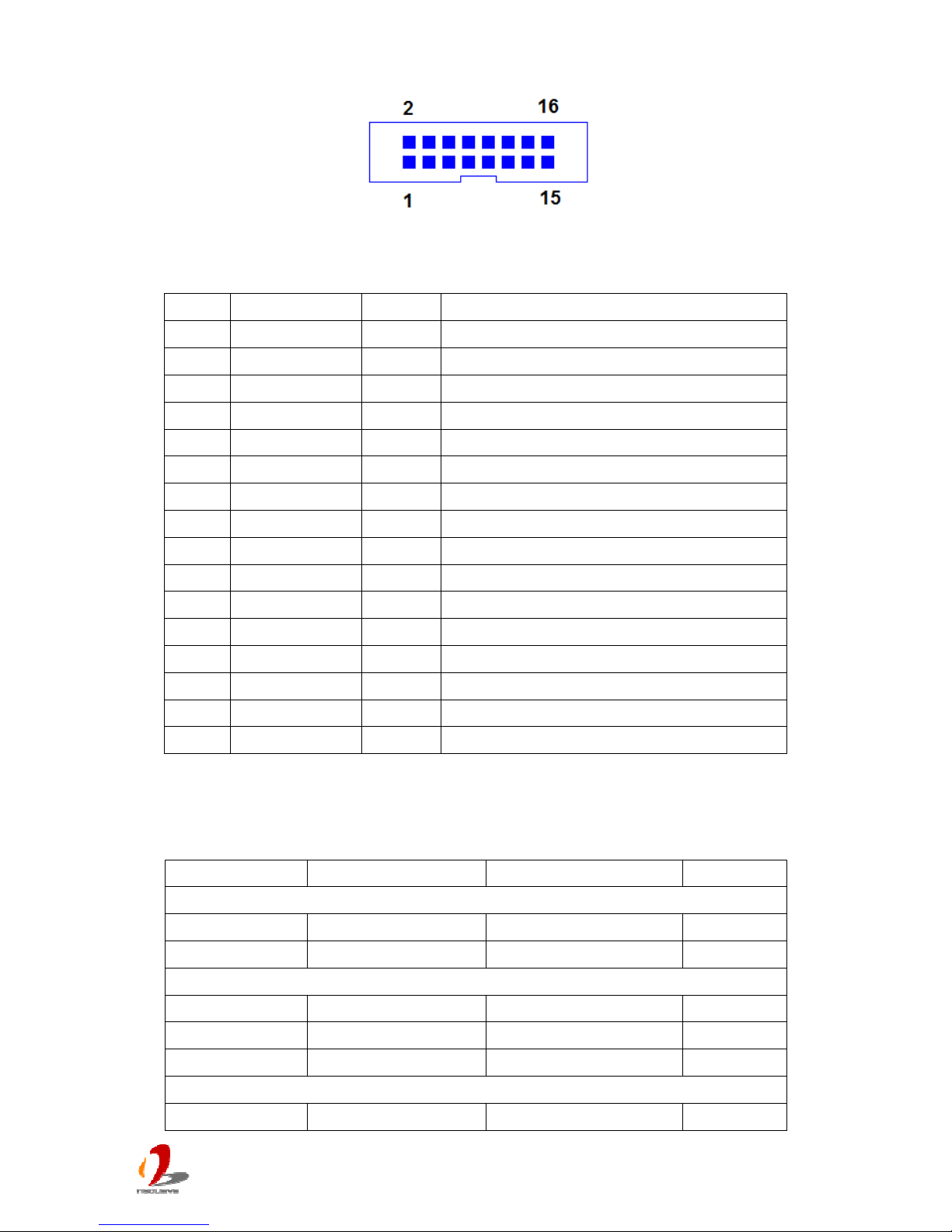
POC-200 integrates 2500Vrms isolated DIO function for extending application range. This
feature provides 4 channels of isolated digital input and 4 channels of isolated digital output
via a 16-pin box-header connector. The following table describes the pin definition of
isolated DIO connector.
Page 21
POC-200 Series User’s Manual
Copyright © 2014 Neousys Technology Inc. All Right Reserved. Page 21 of 78
Pin Definition
Pin# Definition I/O Description
1 ISO_5V O Isolate 5V power supply
2 VDD I DO voltage source input for inductive load
3 DI_0 I Digital input channel 0
4 VDD I DO voltage source input for inductive load
5 DI_1 I Digital input channel 1
6 DO_0 O Digital output channel 0
7 DI_GND - Digital input GND
8 DO_1 O Digital output channel 1
9 DI_2 I Digital input channel 2
10 DO_GND - Digital output GND
11 DI_3 I Digital input channel 3
12 DO_2 O Digital output channel 2
13 DI_GND - Digital input GND
14 DO_3 O Digital output channel 3
15 DI_GND - Digital input signal
16 DO_GND - Digital output GND
Electrical Characteristics
Parameeter Description Min Typ Max
DO Channel [0:3]
V_DO DO output voltage 24 V
I_DO DO current limit 100 250 mA
DI Channel [0:3]
V_DI High Input voltage High 5 24 V
V_DI Low Input voltage Low 0 1.5 V
I_DI Input current 20 mA
Voltage ISO_5V
V_ISO5V Voltage 4.75 5 5.25 V
Page 22
POC-200 Series User’s Manual
Copyright © 2014 Neousys Technology Inc. All Right Reserved. Page 22 of 78
I_ISO5V Curre
nt 200 mA
Input Parameter
Resistor Input resistor 2.4 Kohm
Isolated voltage
2500 V rms
2.2.9.2 5V TTL GPIO on POC-210/POC-212/POC-222
POC-210/212/222 offers 8-CH 5V TTL GPIO for general-purpose usage. By default, these
channels are configured as 4 channels of digital input and 4 channels of digital output. The
following table describes the pin definition of isolated DIO connector.
Pin Definition
Pin# Definition I/O Description
1
N.C
- No connection
2
N.C
- No connection
3
DI_0
I Digital input channel 0
4
N.C.
- No connection
5
DI_1
I Digital input channel 1
6
DO_0
O Digital output channel 0
7
N.C.
- No connection
Page 23

POC-200 Series User’s Manual
Copyright © 2014 Neousys Technology Inc. All Right Reserved. Page 23 of 78
8
DO_1
O
Dig
i
tal output channel 1
9
DI_2
I Digital input channel 2
10
D_GND
GND Digital GND
11
DI_3
I Digital input channel 3
12
DO_2
O Digital output channel 2
13
N.C.
- No connection
14
DO_3
O Digital output channel 3
15
N.C.
- No connection
16
D_GND
GND Digital GND
Page 24
POC-200 Series User’s Manual
Copyright © 2014 Neousys Technology Inc. All Right Reserved. Page 24 of 78
2.3 Back Panel I/O Functions
To fit more general application requirements, POC-200 series offers more I/O functions on
its ba
ck panel. In this section, we’ll illustrate each I/O function on the back panel.
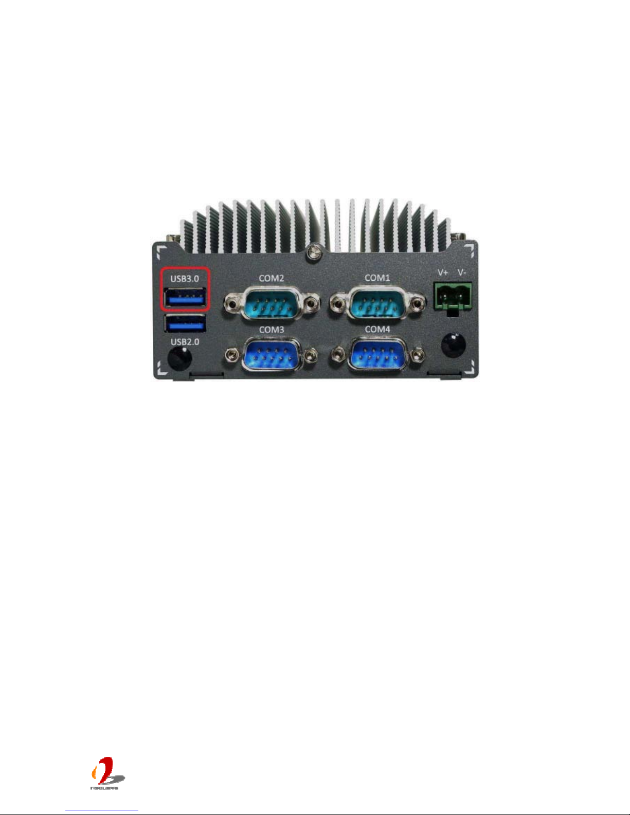
2.3.1 USB3.0 Connectors
There are totally three USB 3.0 ports and one USB 2.0 port on POC-200 series. One of
three USB 3.0 ports is located on the back panel. This USB 3.0 port is implemented via
native xHCI controller inside Bay Trail SoC. By BIOS default, this USB port is operated in
xHCI (eXtensible Host Control Interface) mode and is compatible to USB 3.0, USB 2.0,
USB 1.1 and USB 1.0 devices.
To utilize USB 3.0 function in Windows, you need to install corresponding USB3 driver for
Bay Trail SoC. Please refer to section 4.3 for information of driver installation.
Page 25
POC-200 Series User’s Manual
Copyright © 2014 Neousys Technology Inc. All Right Reserved. Page 25 of 78
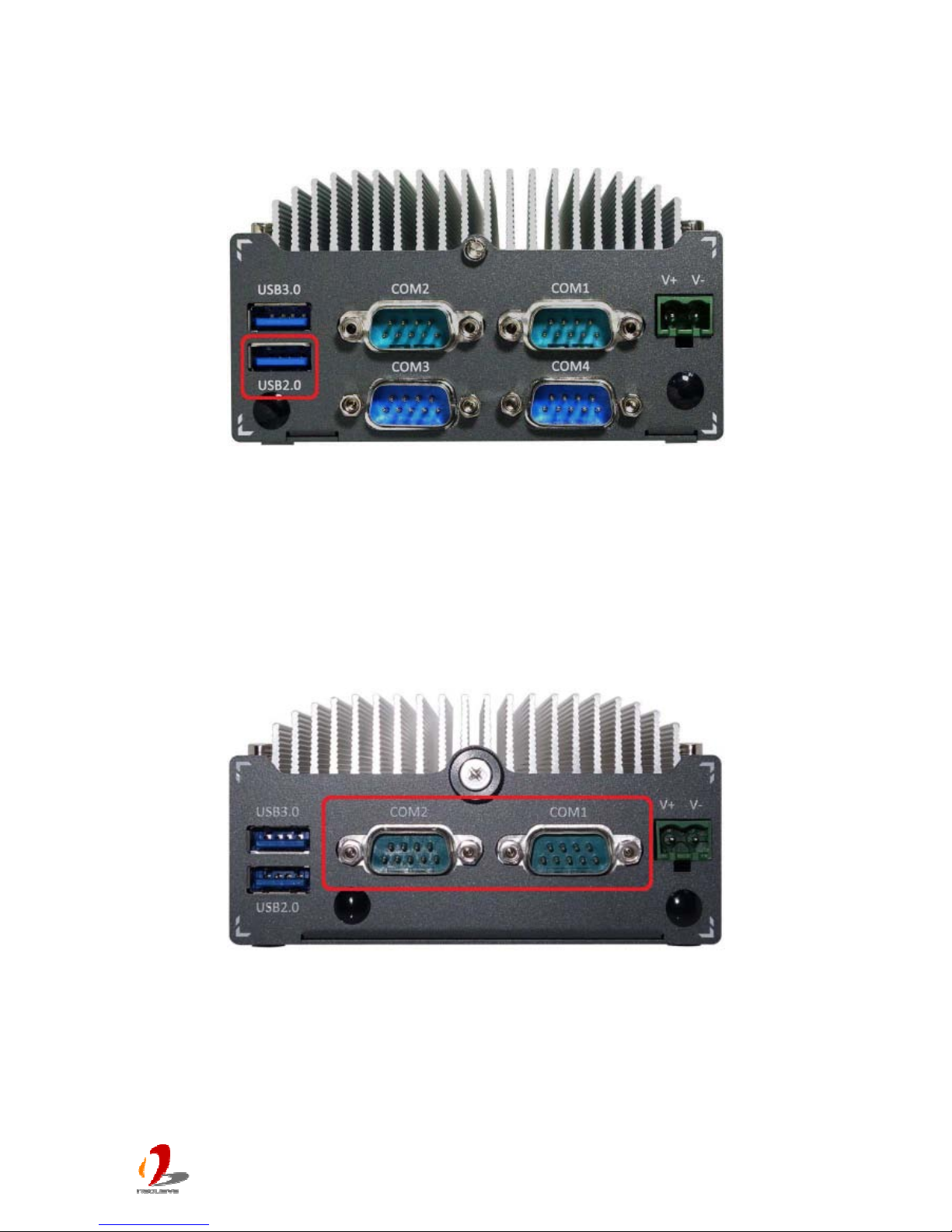
2.3.2 USB2.0 Connectors
In addition to three USB 3.0 ports, POC-200 series provides another USB 2.0 port on its
back panel. By BIOS default, these USB 2.0 ports are operated in EHCI (Enhanced Host
Control Interface) mode and are compatible with USB 2.0, USB 1.1 and USB 1.0 devices.
Legacy USB support is provided so you can use USB keyboard/mouse in DOS
environment.
2.3.3 COM Ports on POC-212/222
POC-212 and POC-222 provide two COM ports via two 9-pin D-Sub male connectors on
the back panel for communicating with external devices. They are implemented using
industrial-grade ITE8783 Super IO chip (-40 to 85°C) and provide up to 115200 bps baud
rate.
COM1 is a software-selectable RS-232/422/485 port and COM2 supports RS-232 only. The
operation mode of COM1 can be set in BIOS setup utility (refer to section 4.1.1 for detail).
The following table describes the pin definition of COM ports.
Page 26
POC-200 Series User’s Manual
Copyright © 2014 Neousys Technology Inc. All Right Reserved. Page 26 of 78
COM1 COM2
Pin# RS-232 Mode RS-422 Mode
RS-485 Mode
(Two-wire 485)
RS-232 Mode
1
DCD DCD
2
RX 422 TXD+ 485 TXD+/RXD+
RX
3
TX 422 RXD+ TX
4
DTR 422 RXD- DTR
5
GND GND GND GND
6
DSR DSR
7
RTS RTS
8
CTS 422 TXD- 485 TXD-/RXD- CTS
9
RI RI
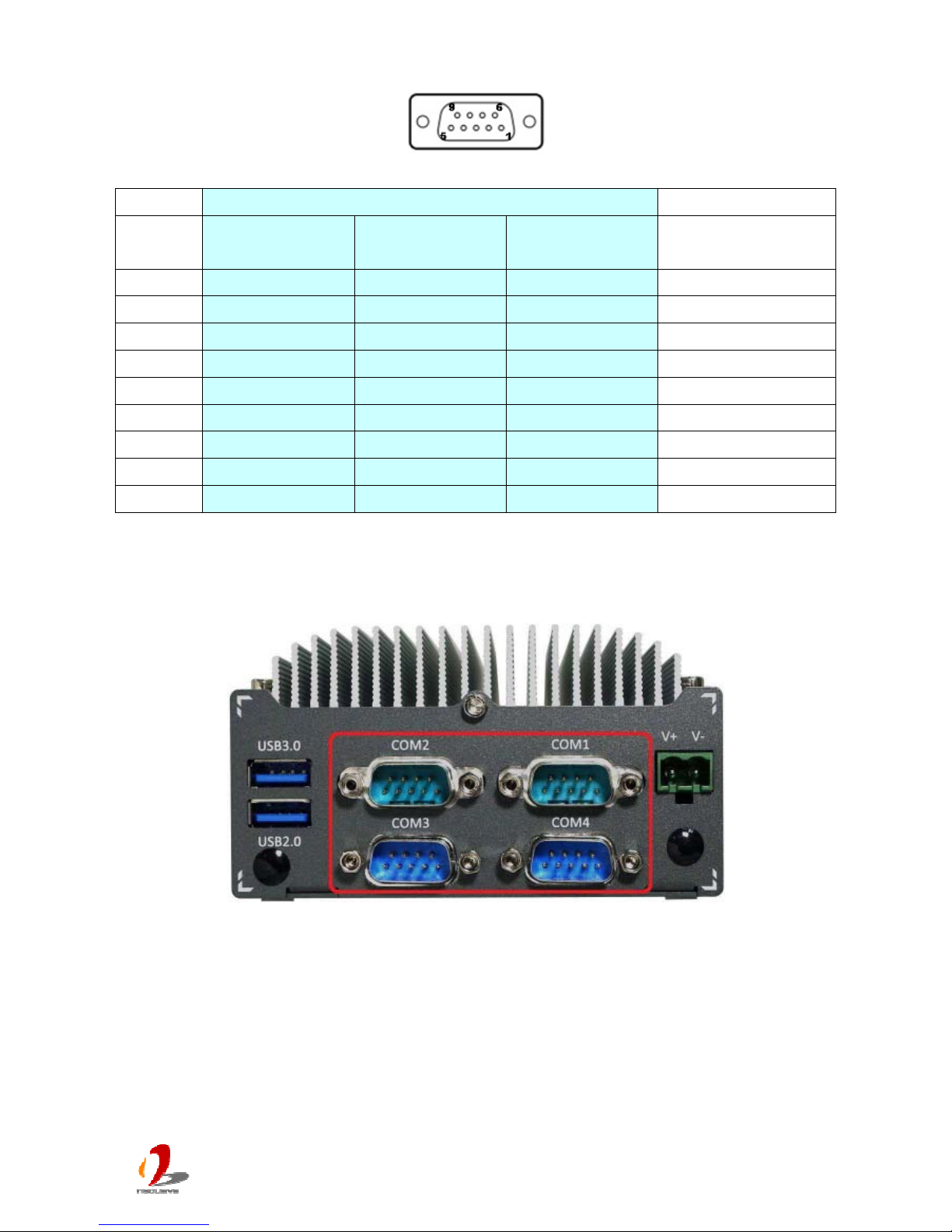
2.3.4 COM Ports on POC-200/210
POC-200 and POC-210 provide four COM ports via four 9-pin D-Sub male connectors on
the back panel for communicating with external devices. They are implemented using
industrial-grade ITE8783 Super IO chip (-40 to 85°C) and provide up to 115200 bps baud
rate.
COM1/COM3 are software-selectable RS-232/422/485 ports and COM2/COM4 support
RS-232 only. The operation mode of COM1/COM3 can be set in BIOS setup utility (refer to
section 4.1.1/4.1.2 for detail). The following table describes the pin definition of COM ports.
Page 27
POC-200 Series User’s Manual
Copyright © 2014 Neousys Technology Inc. All Right Reserved. Page 27 of 78
COM1/COM3 COM2/COM4
Pin# RS-232 Mode RS-422 Mode
RS-485 Mode
(Two-wire 485)
RS-232 Mode
1
DCD DCD
2
RX 422 TXD+ 485 TXD+/RXD+
RX
3
TX 422 RXD+ TX
4
DTR 422 RXD- DTR
5
GND GND GND GND
6
DSR DSR
7
RTS RTS
8
CTS 422 TXD- 485 TXD-/RXD- CTS
9
RI RI
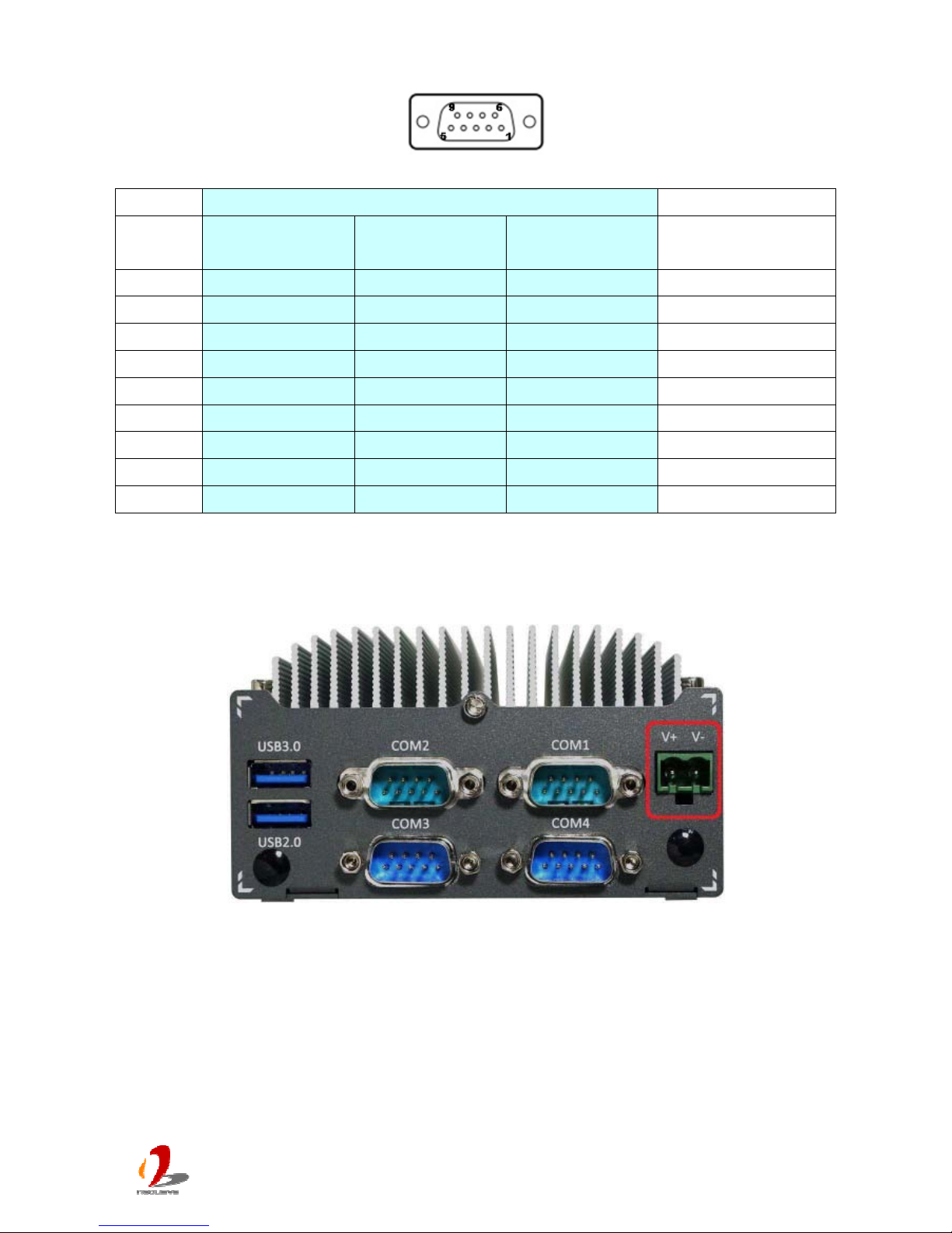
2.3.5 2-Pin Terminal Block for DC Input
POC-200 series features a pluggable terminal block for direct DC wiring. The 2-pin
pluggable terminal block on the back panel is fit for field usage where DC power is usually
provided. It accepts a wide range of DC power input from 8 to 35V. And the screw clamping
connection of terminal block gives a very reliable way for wiring the DC power. The
following table describes the pin definition of the pluggable terminal block. For detail
information of connecting DC power, please refer to section 3.6.
Page 28

POC-200 Series User’s Manual
Copyright © 2014 Neousys Technology Inc. All Right Reserved. Page 28 of 78
Pin Descrip
tion
V+ Positive polarity of DC power input (8 ~ 35V).
V- Negative polarity of DC power input (usually power ground).
Caution
Please make sure the voltage and polarity of DC power is correct before you connect it to POC-200.
Supplying a voltage over 35V will damage the system..
Page 29
POC-200 Series User’s Manual
Copyright © 2014 Neousys Technology Inc. All Right Reserved. Page 29 of 78
2.4 Internal I/O Functions
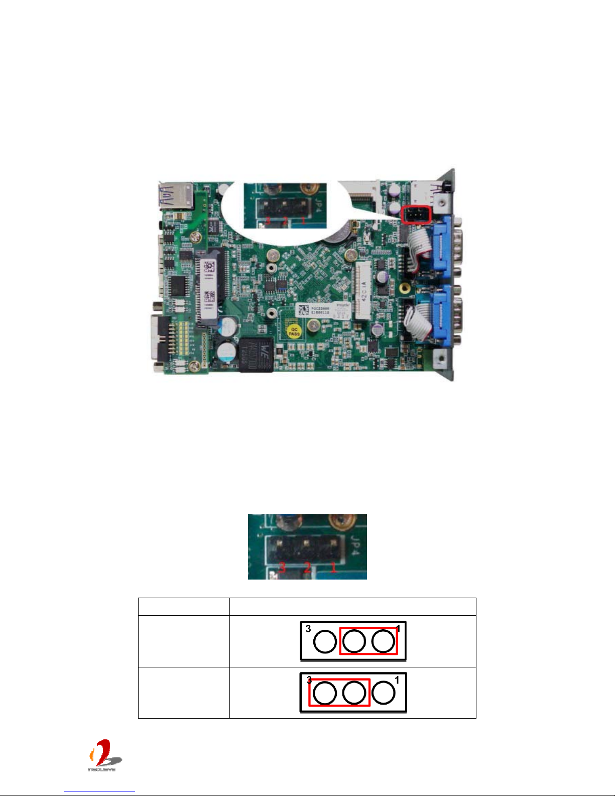
2.4.1 Remote On/Off Control
The remote on/off control function allows users to turn on or turn off the system remotely by
connecting an external switch. This function is provided via a 1x3 pins, 2.0mm pitch pin
header.
Both AT-mode and ATX-mode on/off control are supported. For detail information of using
remote on/off control function, please refer to section 3.7.2/3.7.3.
Switch Connection for AT/ATX Mode Remote On/Off Control
Mode Jumper Setting
AT
ATX
Page 30
POC-200 Series User’s Manual
Copyright © 2014 Neousys Technology Inc. All Right Reserved. Page 30 of 78
2.4.2 Mini PCI Express Connector and SIM Socket
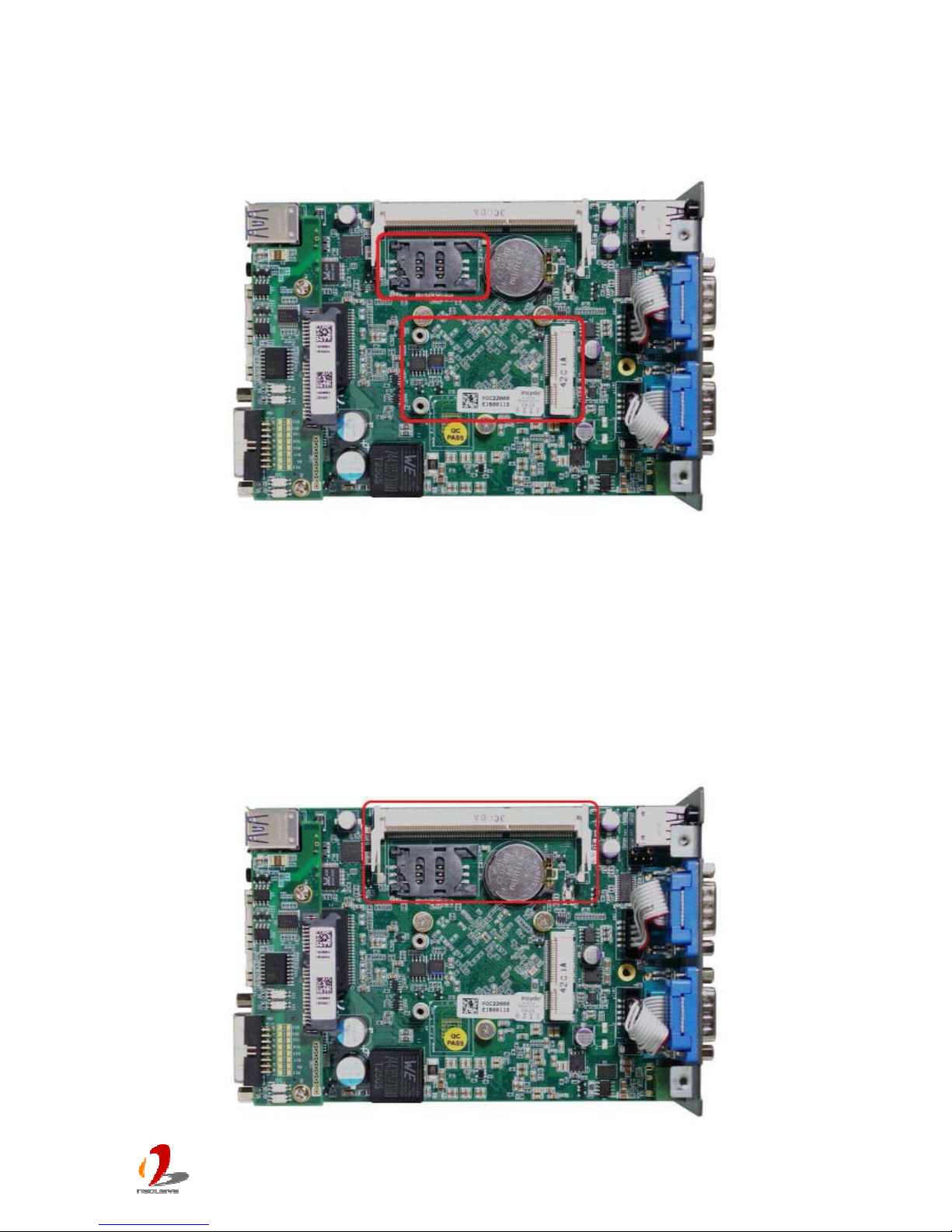
POC-200 series provides an on-board Mini PCI Express socket with SIM card support.
There are plenty of off-the-shelf mini-PCIe modules with versatile capabilities. By installing
a mini-PCIe module, your system can have expanded features such as WIFI, 3G, GPS,
RAID and etc. In addition, the SIM card support makes it possible to connect your system to
Internet in wide territory through telecom operator’s GPRS/3G network.
2.4.3 DDR3L SODIMM Socket
Page 31
POC-200 Series User’s Manual
Copyright © 2014 Neousys Technology Inc. All Right Reserved. Page 31 of 78
POC-200 series provides one 204-pin, SODIMM socket for memory installation. It supports
a max
imal 8GB capacity by installing one low-voltage 1.35V DDR3L-1333 SODIMM
modules. For information of installing DDR3L memory modules, please refer to section 3.2
for detail.
Note
Please make sure you’re installing a 1.35V DDR3L SODIMM module to POC-200. Installing a 1.5V
DDR3 SODIMM will cause system failed to boot.
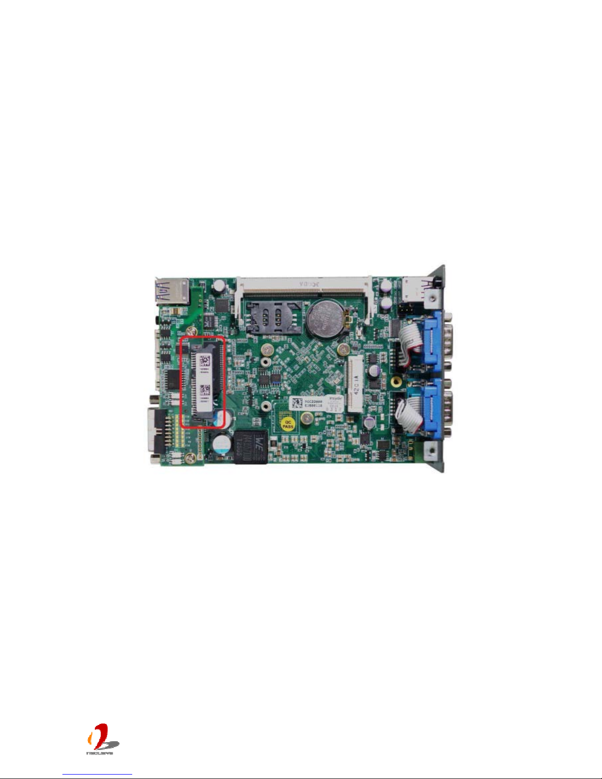
2.4.4 SATA Connector
POC-200 series provides one SATA port to accommodate a 2.5” SATA hard drive inside it.
The SATA port is located on the daughter board via a 22-pin SATA connector. With the
HDD bracket shipped with POC-200 series, you can directly mount a 2.5” HDD or SSD to
this port. For information of installing a HDD/SSD to SATA port, please refer to section 3.3
for detail.
Page 32
POC-200 Series User’s Manual
Copyright © 2014 Neousys Technology Inc. All Right Reserved. Page 32 of 78
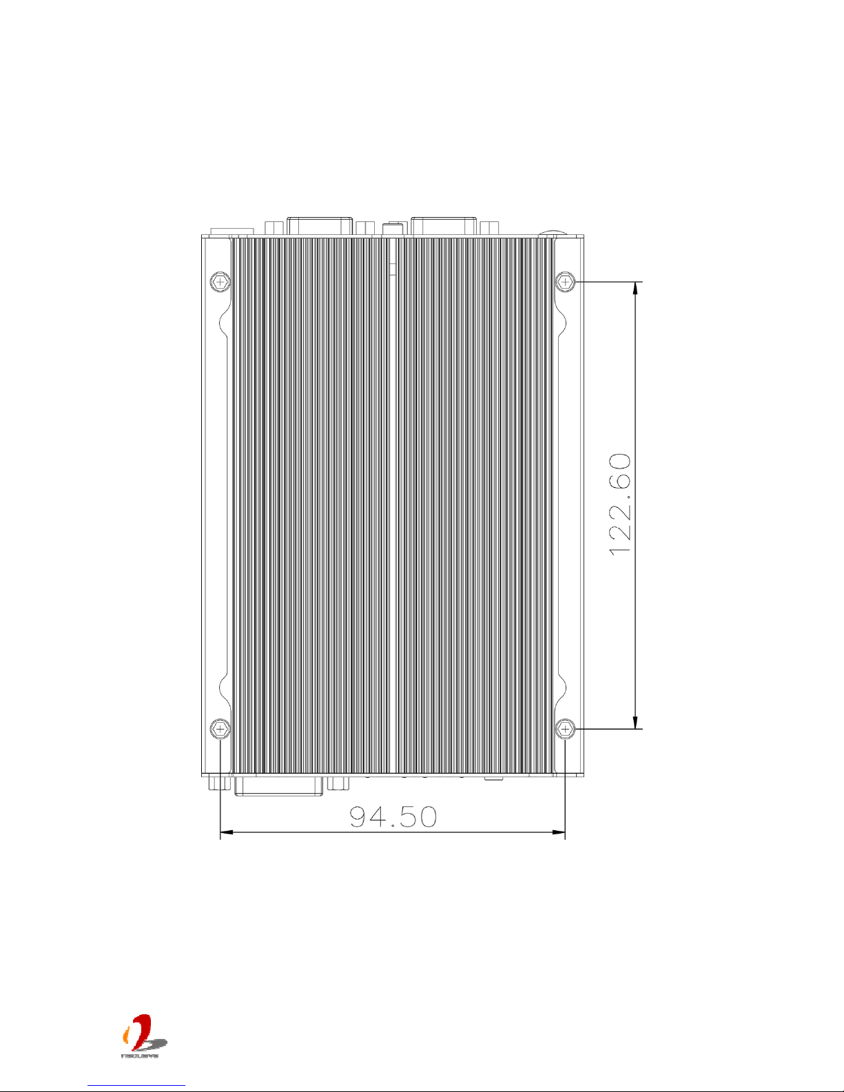
2.5 POC-200/210 Mechanical Dimension
2.5.1 Top View
Page 33
POC-200 Series User’s Manual
Copyright © 2014 Neousys Technology Inc. All Right Reserved. Page 33 of 78
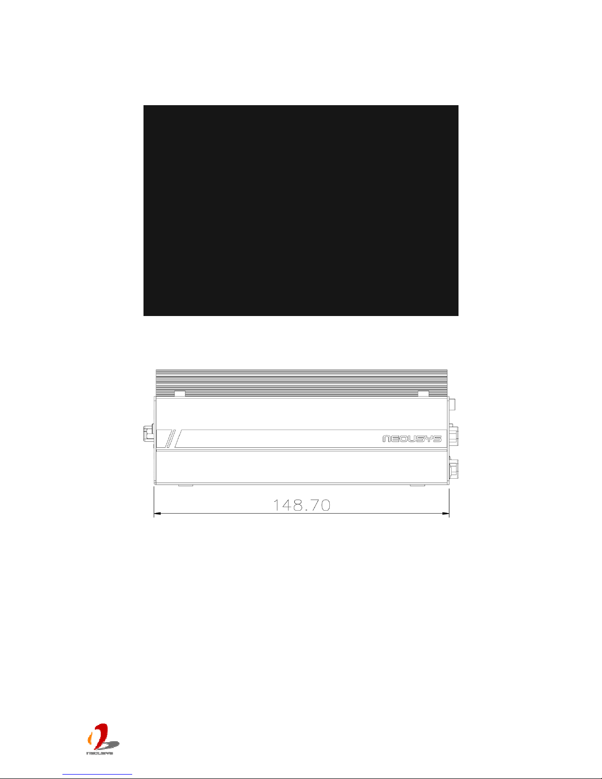
2.5.2 Front View
2.5.3 Side View
Page 34
POC-200 Series User’s Manual
Copyright © 2014 Neousys Technology Inc. All Right Reserved. Page 34 of 78
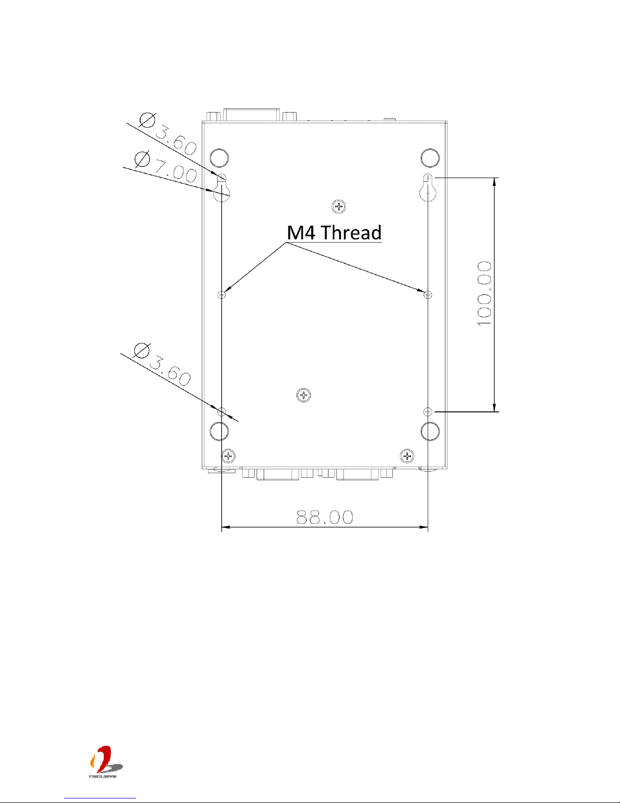
2.5.4 Bottom View
Page 35
POC-200 Series User’s Manual
Copyright © 2014 Neousys Technology Inc. All Right Reserved. Page 35 of 78
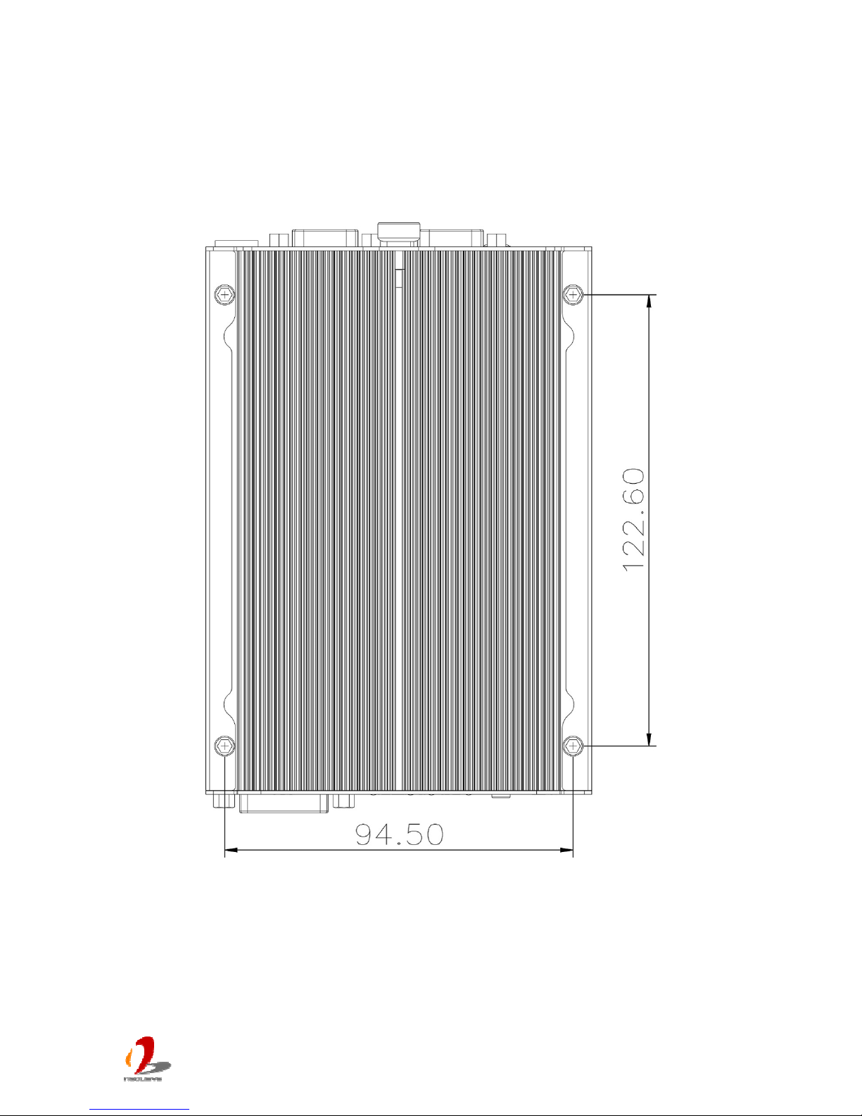
2.6 POC-212/222 Mechanical Dimension
2.6.1 Top View
Page 36
POC-200 Series User’s Manual
Copyright © 2014 Neousys Technology Inc. All Right Reserved. Page 36 of 78
2.6.2 Front View
2.6.3 Side View
Page 37
POC-200 Series User’s Manual
Copyright © 2014 Neousys Technology Inc. All Right Reserved. Page 37 of 78
2.6.4 Bottom View
Page 38
POC-200 Series User’s Manual
Copyright © 2014 Neousys Technology Inc. All Right Reserved. Page 38 of 78
Chapter 3 Getting Start
In this chapter, we’ll illustrate how to disassemble your POC-200 and install peripheral
device
s. Please note that the procedures might be varied for different POC-200 models.
Please follow the correct procedures to prevent any damage on your POC-200 series.
3.1 Dissemble your POC-200 Series
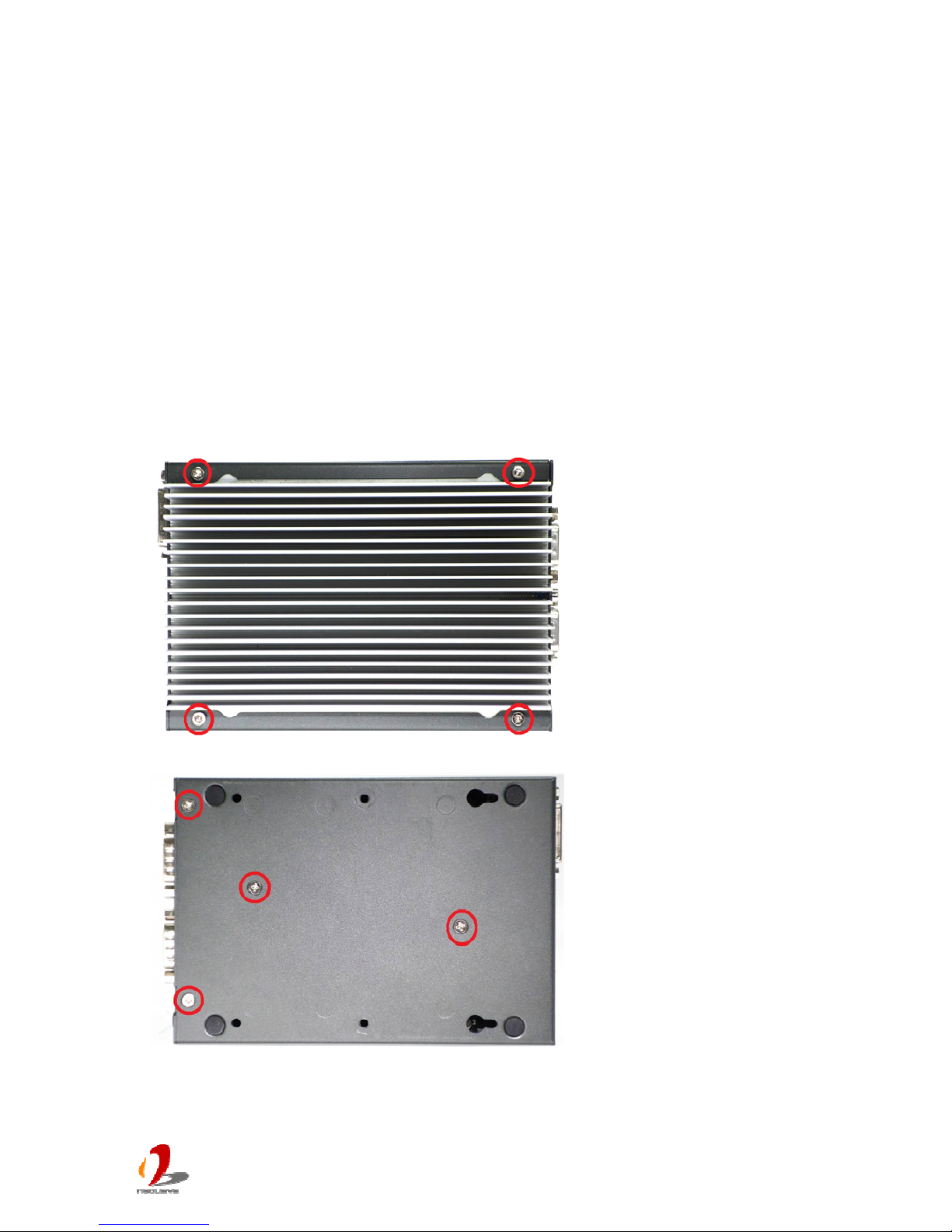
3.1.1 Dissemble POC-200/210
1. Unscrew 4 hex bolts on the top of the heat sink.
2. Unscrew four M3 F-head screws on the bottom side.
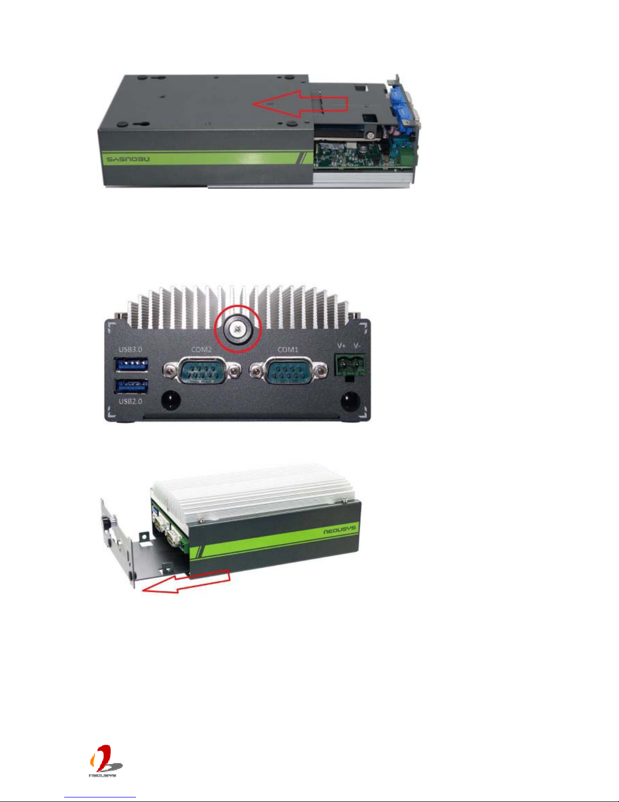
Page 39
POC-200 Series User’s Manual
Copyright © 2014 Neousys Technology Inc. All Right Reserved. Page 39 of 78
3. Gently slide out the assembly of case and you can see the case and the HDD bracket.
3.1.2 Dissemble POC-212/222
1. Unscrew the hand screw on the back panel.
2. Pull the 2.5” HDD bracket out of POC-212/222.
Page 40
POC-200 Series User’s Manual
Copyright © 2014 Neousys Technology Inc. All Right Reserved. Page 40 of 78
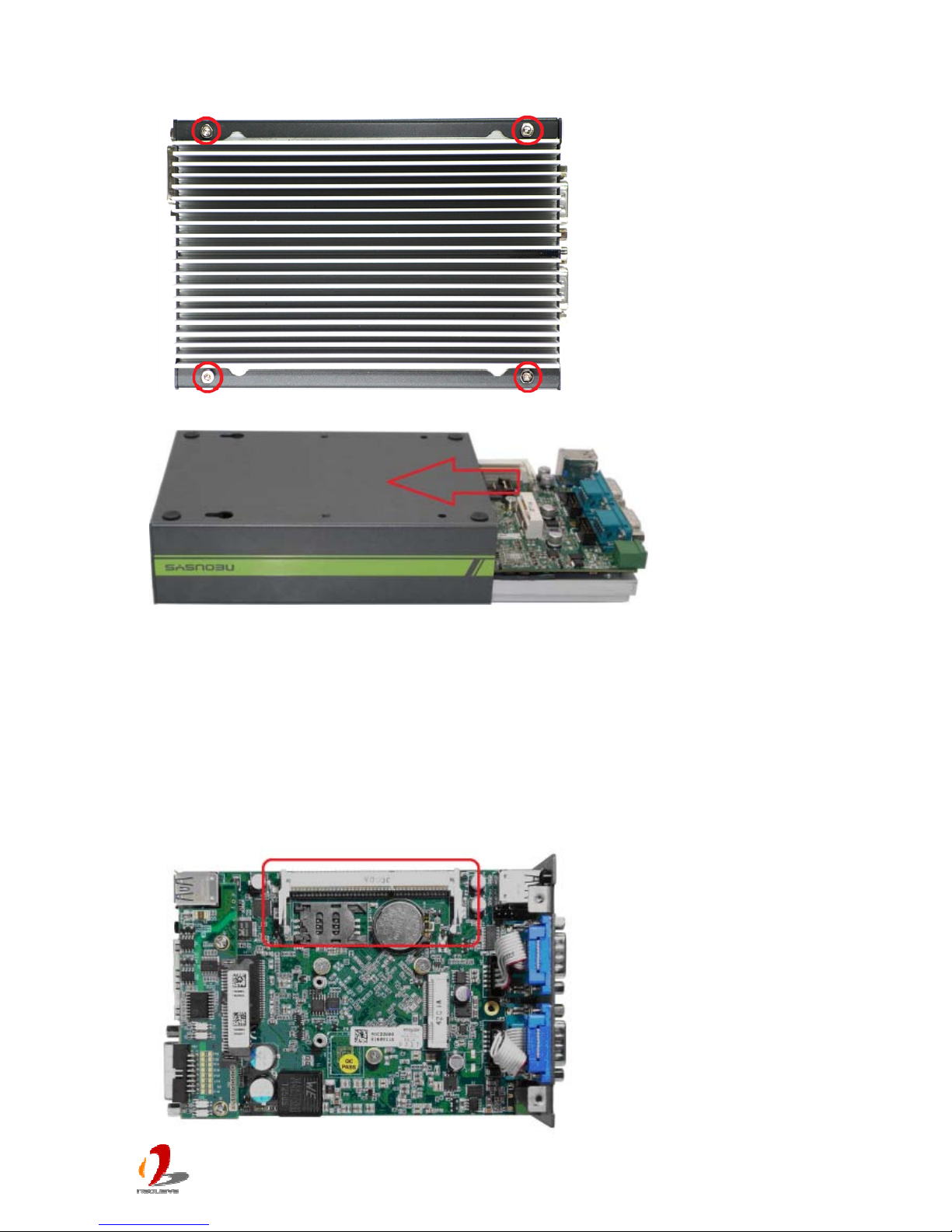
3. Unscrew 4 hex bolts on the top of the heat sink.
4. Gently slide out the assembly of case.
3.2 Install a DDR3L SODIMM Module
Note
Please make sure you’re installing a 1.35V DDR3L SODIMM module on POC-200. Installing a 1.5V
DDR3
SODIMM will cause system failed to boot.
1. Follow the steps in section 3.1.1 (POC-200/210) or section 3.1.2 (POC-212/222) to
dissemble your POC-200 series. You can see the DDR3L socket exposed.
 Loading...