

Page 1

Nuvo-4 0 00 S er i es User’s Man u al
Copyright © 2014 Neousys Technology Inc. All R ight Reserved. Page 1 of 76
Neousys Technology Inc.
Nuvo-4000 Series
Intel® 3rd-Gen Core™ i7/i5 Fanless Box-PC
with 4x PCIe/PCI Expa nsion Slots
Nuvo-4022 / Nuvo-4040
User ’s Manual
Rev. A1
Published April 17th, 2014
Page 2

Nuvo-4 0 00 S er i es User’s Man u al
Copyright © 2014 Neousys Technology Inc. All Right Reserved. Page 2 of 76
Contents
Declaimer ............................................................................................................................. 4
Declaration of Conformity ............................................................................................. 4
FCC ................................................................................................................... 4
CE ...................................................................................................................... 4
Copyright and Tr ademarks ........................................................................................... 4
Chapter 1 Introduction ......................................................................................................... 5
1.1 Overview. ................................................................................................................ 5
1.2 Product Specification .............................................................................................. 6
1.2.1 Specification of Nuvo-4022 ....................................................................... 6
1.2.2 Specification of Nuvo-4040 ....................................................................... 8
1.2.3 Specification of Optional Isolated DIO ..................................................... 10
Chapter 2 Getting to know your Nuvo-4000 ....................................................................... 11
2.1 Unpacking your Nuvo-4000 .................................................................................. 11
2.2 Front Panel I/O Functions ..................................................................................... 12
2.2.1 Power Button .......................................................................................... 12
2.2.2 Reset Button ........................................................................................... 12
2.2.3 LED Indicators ........................................................................................ 13
2.2.4 USB 3.0 Connectors ............................................................................... 13
2.2.5 Gigabit Ethernet Port............................................................................... 14
2.2.6 DVI-I Connector ...................................................................................... 15
2.2.7 DVI-D Connector ..................................................................................... 15
2.2.8 COM Ports .............................................................................................. 16
2.2.9 Speaker-Out Jack ................................................................................... 17
2.2.10 4-Pin Mini-DIN Power Connector .......................................................... 17
2.3 Internal I/O Functions ........................................................................................... 19
2.3.1 Status LED Output & Remote On/Off Control.......................................... 19
2.3.2 Internal USB2.0 Pin Header .................................................................... 20
2.3.3 CFast Socket .......................................................................................... 21
2.3.4 DDR3 SODIMM Socket ........................................................................... 22
2.3.5 SATA Connectors .................................................................................... 23
2.3.6 PCI Slots ................................................................................................. 23
2.3.7 PCI Express Slots (Nuvo-4022 Only) ...................................................... 24
2.3.8 Optional Isolated DIO .............................................................................. 26
2.4 Mechanical Dimension .......................................................................................... 28
2.4.1 Front View ............................................................................................... 28
2.4.2 Back View ............................................................................................... 29
2.4.3 Top View.................................................................................................. 30
2.4.4 Bottom View ............................................................................................ 31
2.4.5 Right View ............................................................................................... 32
Page 3

Nuvo-4 0 00 S er i es User’s Man u al
Copyright © 2014 Neousys Technology Inc. All Right Reserved. Page 3 of 76
2.4.6 Left View ................................................................................................. 33
Chapter 3 Getting Start ...................................................................................................... 34
3.1 Install the SATA HDD/SSD .................................................................................... 34
3.2 Install a CFast card ............................................................................................... 37
3.3 Install the DDR3 SODIMM Module ....................................................................... 38
3.4 Install the PCI/PCIe Add-on Card ......................................................................... 39
3.5 Mount your Nuvo-4000 ......................................................................................... 40
3.5.1 Mount your Nuvo-4000 on the Wall ......................................................... 40
3.5.2 Mount your Nuvo-4000 on a Flat Surface ............................................... 42
3.5.3 Mount your Nuvo-4000 on the DIN Rail .................................................. 44
3.6 Connect DC power to you Nuvo-4000 .................................................................. 45
3.7 Power on your Nuvo-4000 .................................................................................... 46
3.7.1 Power on Nuvo-4000 using the power button on the front panel............. 46
3.7.2 Power on Nuvo-4000 using Wake-on-LAN function ................................ 46
Chapter 4 BIOS and Driver ................................................................................................ 50
4.1 BIOS Settings ....................................................................................................... 50
4.1.1 COM1 & COM2 Operating Mode ............................................................ 50
4.1.2 SATA Controller Mode ............................................................................. 51
4.1.3 XHCI Support .......................................................................................... 52
4.1.4 Video Configuration ................................................................................. 53
4.1.5 VGA Output Resolution ........................................................................... 54
4.1.6 Power On after Power Failure Option ..................................................... 55
4.1.7 Wake-on-LAN Option .............................................................................. 56
4.1.8 Watchdog Timer for Booting .................................................................... 57
4.1.9 Select a Boot Device ............................................................................... 58
4.2 Operating System Support.................................................................................... 59
4.3 Driver Insta llation .................................................................................................. 60
4.3.1 Install all drivers using “One-Click ” d river ins tal lation .............................. 60
4.3.2 Install drivers manually ............................................................................ 61
Appendix A Using Watchdog T im er & Isolated DIO ............................................................ 63
A.1 Install WDT and DIO Library ................................................................................. 64
A.2 Using WDT Function ............................................................................................ 66
WDT Function Reference ................................................................................. 66
A.3 Using DIO Function .............................................................................................. 68
Wiring for DIO .................................................................................................. 68
DIO Function Reference .................................................................................. 69
A.4 Using COS Function ............................................................................................. 72
Change-of-State DIO Function Reference ....................................................... 72
Change-of-State DI Example ........................................................................... 74
Page 4

Nuvo-4 0 00 S er i es User’s Man u al
Copyright © 2014 Neousys Technology Inc. All Right Reserved. Page 4 of 76
Declaimer
This manual is intended to be used as a practical and informative guide only and is subject
to change without prior not ice. It do es not rep r esent com mitment from Neousys Technology
Inc. Neousys shall not be liable for direct, indirect, special, incidental, or consequential
damages arising out of the use of the product or documentation, nor for any infringem ents
upon the rights of third parties, which may result from such use.
Declaration of Conformity
FCC
This equipment has been tested and found to comply with the limits for a Class A digital
device, pursuant to part 15 of the FCC Rules. These limits are designed to provide
reasonable protection against harmful interference when the equipment is operated in a
commercial environm ent. This equ ipm ent gen erates , uses, and c an ra d iate rad io frequenc y
energy and, if not installed and used in accordance with the instruction manual, may cause
harmful interference to radio communications. Operation of this equipment in a residential
area is likely to cause harm f ul interference in w hich case the user will be required to corr ect
the interference at his own expense.
CE
The product(s) described in this manual complies with all applicable European Union (CE)
directives if it has a CE marking. For computer systems to remain CE compliant, only
CE-compliant parts may be used. Maintaining CE compliance also requires proper cable
and cabling techniques.
Copyright and Trademarks
This document contains proprietary information protected by copyright. All rights are
reserved. No part of this document may be reproduced by any mechanical, electronic, or
other means in any form without prior written permission of the manufacturer.
Company/product names mentioned herein are used for identification purposes only and
are trademarks and/or registered trademar ks of their respective companies.
Page 5
Nuvo-4 0 00 S er i es User’s Man u al
Copyright © 2014 Neousys Technology Inc. All Right Reserved. Page 5 of 76
Chapter 1 Introduction
1.1 Overview.
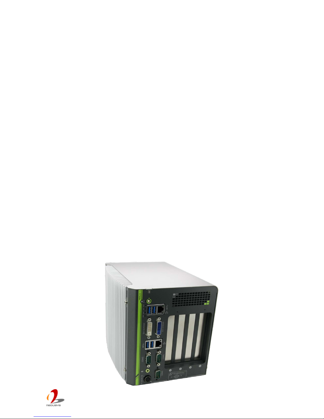
Nuvo-4000 is a high-performance box-pc with fanless design and small footprint. It
incorporates Intel® 3rd-Gen i7/i5 processor to offer extraordinary computing power, and
fanless architecture to offer reliable operation in various environments.
The 4-slots expandability makes Nuvo-4000 very versatile. Nuvo-4022 features two Gen2
PCI Express slots and delivers a total of 6 GB/s bandwidth for applications demanding
high-speed data transmission. A notable 48W power budget is dedicatedly supplied to the
x16 PCIe slot for powering a high-watt PCIe card (e.g. a graphics card). Nuvo-4022/4040
also has PCI slots to accommodate up to 4 PCI cards for general industrial automation and
test & measurement applications.
Nuvo-4000 features the smallest foot-print for a fanless box-pc with four expansion slots. It
supports ample I/O interfaces for communication/control purpose, and implements
DVI+DVI+VGA triple independent display outputs for video/image related applications. An
option of smart fan is ava ilab le for bette r oper ating re l iabil ity w hen high-w att cards inst a lled.
The combination of high performance, small foot-print and versatility makes Nuvo-4000 not
only an ideal application platform, but also a great replacement of traditional rack-mount or
wall-mount IPC.
Page 6
Nuvo-4 0 00 S er i es User’s Man u al
Copyright © 2014 Neousys Technology Inc. All Right Reserved. Page 6 of 76
1.2 Product Specification
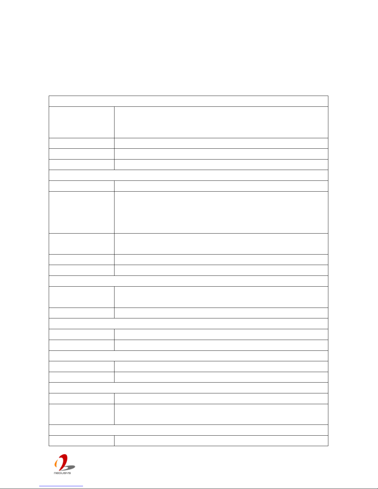
1.2.1 Specification of Nuvo-4022
System Core
Processor
Intel® Core™ i7-3610Q E (2. 3/3.3 GHz, 6 MB cache)
Intel® Core™ i5-3610ME (2.7/3.3 GHz, 3 MB cache)
Intel® Celer on™ 1020E (2.2 GHz, 2 MB cache)
Chipset Intel® HM76 Platform Cont r oller Hub
Graphics Integrated I ntel® HD Graphics 4000 Controller
Memory 2x 204-pin SO-DIMM sockets, up to 16 GB DDR3 1333/1600 MHz SDRAM
Front-p anel I/O Inte r fa c e
Ethernet 2x Gigabit Ethernet ports by Intel® I210
Video Port
1x DVI-I connector for VGA and DVI/HDMI outputs, supporting 1920x1080
resolution
1x DVI-D connectors for DVI/HDMI output, supporting 1920x 1080 r esol ution
(Supporting triple independent display outputs)
Serial Port
2x software-programmable RS-232/422/485 (COM1 & COM2)
1x RS-232 (COM3)
USB 4x USB 3.0 ports
Audio 1x Speaker-out
Expansion Bus
PCI Express
1x PCIe x16 sl ot @ 8-lanes PCIe signal with dedicated 48W power budget
1x PCIe x4 slot with shared 48W power budget
PCI 2x 33MHz/32-bit 5V PC I slots
Internal I/O Interf ace
USB 2x USB 2.0 ports via 10-pin box-header
Isolated DIO Optional 8-CH isolated DI + 8-CH isolated DO
Storage Interface
SATA HDD 2x Internal SATA ports for 2.5” HDD/SSD installati on
CFast 1x CFast socket
Power Su pp ly
DC Input 1x 4-pin power connector for 8~25V DC input
Power Consumpti on
With i7-3610QE: 66.12W (3.48A@19V)*
With i5-3610ME : 43.13W (2.27A@19V)*
Mechanical
Dimension 164 mm (W) x 178 mm (D) x 225 mm (H)
Page 7
Nuvo-4 0 00 S er i es User’s Man u al
Copyright © 2014 Neousys Technology Inc. All Right Reserved. Page 7 of 76
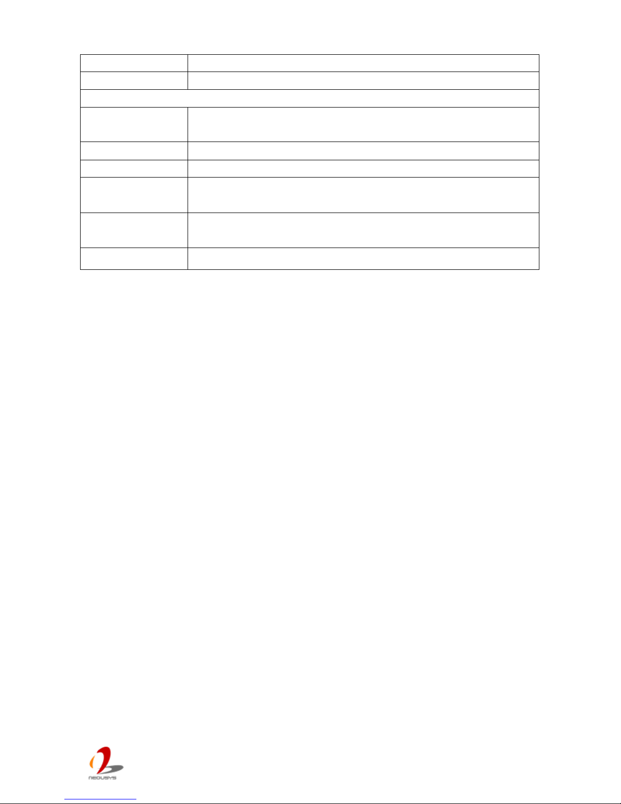
Weight 4.0 kg (with one 2.5” HDD and DDR3 memory module)
Mounting Wall-mounting (Standard) or DIN-Rail mounting (Optional)
Environmental
Operating
Temperature
-20°C ~ 60°C, 100% CPU loading **/***
Storage Temperature
-40°C ~85°C
Humidity 10%~90% , non-condensing
Vibration
Operating, 5G rms, 5-500 Hz, 3 Axes
(w/ SSD, w/o add-on card, acc or ding to IEC60068-2-64)
Shock
Operating, 50G rms, Half-sine 11ms Duration
(w/ SSD, w/o add-on card, acc or ding to IEC60068-2-27)
EMC
CE/FCC Class A, according to EN 55022 & EN 55024
* Full-loading power consum ption is measured with 2GB DDR3 memory and one 2.5” SATA HDD installed
under the following conditions:
- 100% loading for CPU
- 100% loading for 3D graphics
- 100% loading for GbE port
** 100% CPU loading is applied using Intel® T her m al Analysis Tool. For detail testing criteria, please contact
Neousys Technology
*** For sub-zero operating tem per ature, a wide temperature HDD drive or S olid State Disk (SSD) is required.
Page 8
Nuvo-4 0 00 S er i es User’s Man u al
Copyright © 2014 Neousys Technology Inc. All Right Reserved. Page 8 of 76
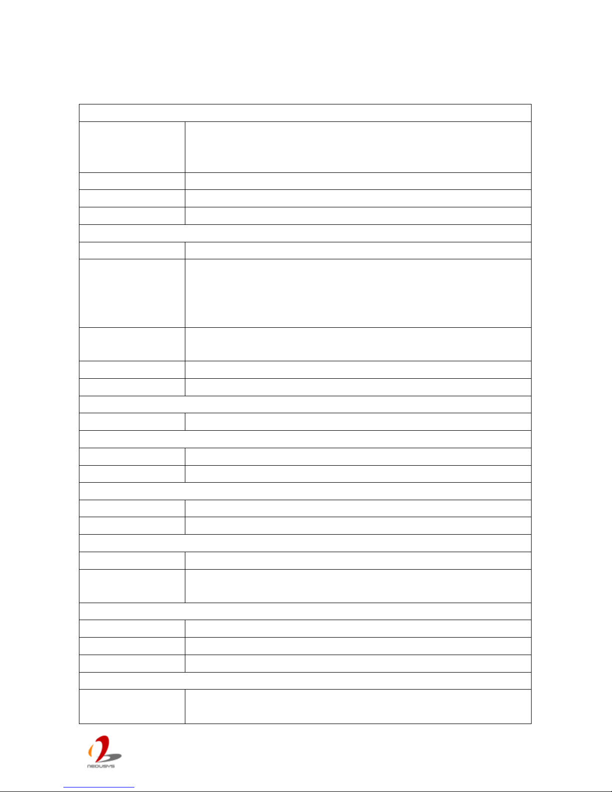
1.2.2 Specification of Nuvo-4040
System Core
Processor
Intel® Core™ i7-3610Q E (2. 3/3.3 GHz, 6 MB cache)
Intel® Core™ i5-3610ME (2.7/3.3 GHz, 3 MB cache)
Intel® Celer on™ 1020E (2.2 GHz, 2 MB cache)
Chipset Intel® HM76 Platform Cont r oller Hub
Graphics Integrated I ntel® HD Graphics 4000 Controller
Memory 2x 204-pin SO-DI MM sockets, up to 16 GB DDR3 1333/1600 MHz S DRAM
Front-p anel I/O Inte r fa c e
Ethernet 2x Gigabit Ethernet ports by Int el® I210
Video Port
1x DVI-I connector for VGA and DVI/HDMI outputs, supporting 1920x1080
resolution
1x DVI-D connector s for DV I/ HDM I out put, supporting 1920x1080 resoluti on
(Supporting triple independent display outputs)
Serial Port
2x software-programmable RS-232/422/485 (COM1 & COM2)
1x RS-232 (COM3)
USB 4x USB 3.0 ports
Audio 1x Speaker-out
Expansion Bus
PCI 4x 33MHz/32-bit 5V PCI slots
Internal I/O Interf ace
USB 2x USB 2.0 ports via 10-pi n box -header
Isolated DIO Optional 8-CH isolated DI + 8-CH isolated DO
Storage Interface
SATA HDD 2x Internal SATA ports for 2.5” HDD/SSD installati on
CFast 1x CFast socket
Power Su pp ly
DC Input 1x 4-pin power connector for 8~25V DC input
Power Consumpti on
With i7-3610QE: 66.12W (3.48A@19V)*
With i5-3610ME : 43.13W (2.27A@19V)*
Mechanical
Dimension 164 mm (W) x 225 mm (D) x 180 mm (H)
Weight 4.0 kg (with one 2.5” HDD and DDR3 memory module)
Mounting Wall-mounting (Standard) or DIN-Rail mounti ng (Optional)
Environmental
Operating
Temperature
-20°C ~ 60°C, 100% CPU loading **/***
Page 9

Nuvo-4 0 00 S er i es User’s Man u al
Copyright © 2014 Neousys Technology Inc. All Right Reserved. Page 9 of 76
Storage Temperature
-40°C ~85°C
Humidity 10%~90% , non-condensing
Vibration
Operating, 5G rms, 5-500 Hz, 3 Axes
(w/ SSD, w/o add-on card, acc or ding to IEC60068-2-64)
Shock
Operating, 50G rms, Half-sine 11ms Duration
(w/ SSD, w/o add-on card, acc or ding to IEC60068-2-27)
EMC
CE/FCC Class A, according to EN 55022 & EN 55024
* Full-loading power consum ption is measured with 2GB DDR3 memory and one 2.5” SATA HDD installed
under the following c onditions:
- 100% loading for CPU
- 100% loading for 3D graphics
- 100% loading for GbE port
** 100% CPU loading is applied using Intel® T her m al Analysis Tool. For detail testing criteria, please contact
Neousys Technology
*** For sub-zero operating tem per ature, a wide temperature HDD drive or S olid State Disk (SSD) is required.
Page 10
Nuvo-4 0 00 S er i es User’s Man u al
Copyright © 2014 Neousys Technology Inc. All Right Reserved. Page 10 of 76
1.2.3 Specification of Optional Isolated DIO
Isolate d Di gital In put
No. of Channel
8-CH Isolated Digital Input Channels
Logic Level
Logic High: 5 to 24V
Logic Low: 0 to 1.5V
Isolated Voltage 2500 Vrms
Input Resistance 2.4kΩ
Isolate d Di gital Ou tput
No. of Channel
8-CH Isolated Digital Output Channels
Sink Current
(per channel)
100 mA (sustained loading)
250 mA (peak loading)
Isolated Voltage 2500 Vrms
Output Type Power MOSFET + Analog Device iCoupler®
Page 11
Nuvo-4 0 00 S er i es User’s Man u al
Copyright © 2014 Neousys Technology Inc. All Right Reserved. Page 11 of 76
Chapter 2 Getting to know your Nuvo-4000
2.1 Unpacking your Nuvo-4000
When you receive the package of Nuvo-4000 series, please check immediately if the
package contains a ll the items listed in the following table. If any item is missing or
damaged, please contact your local dealer or Neousys Technology Inc. for further
assistance.
Item Description Qty
1 Nuvo-4022 or Nuvo-4040 fanless controller
(According to the configuration you orde r, the Nuvo-4022/4040 may
contain HDD and DDR3 SODIMM. Please verify these items if necessary.)
1
2 Accessory box, which contains
SATA HDD bracket
Wall-mounting bracket
Neousys Drivers & Utilities DVD
Screw package
1
2
1
1
Page 12
Nuvo-4 0 00 S er i es User’s Man u al
Copyright © 2014 Neousys Technology Inc. All Right Reserved. Page 12 of 76
2.2 Front Panel I/O Functions
On Nuvo-4000, we design all general-purpose I/O functions on the front panel so you can
easily access them. In this section, we’ll illustrate each I/O function on the front panel.
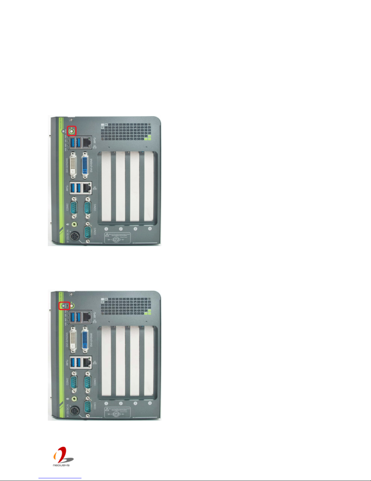
2.2.1 Power Button
The power button is a non-latched switch for ATX
mode on/off operation. To turn on the Nuvo-4000,
press the power button and the PWR LED is lighted
up. To turn off the Nuvo-4000, you can either issue
a shutdown command in OS, or just simply press
the power button. In case of system halts, you can
press and hold the power button for 5 seconds to
compulsorily shut down the system. Please note
that a 5 seconds interval is kept by the system
between two on/off operations (i.e. once turning off
the system, you shall wait for 5 seconds to initiate
another power-on operation).
2.2.2 Reset Button
The reset button is used to manually reset the
system in case of any abnormal condition. To avoid
unexpected operation, the reset button is hidden
behind the front panel. You need to use a pin-like
object to push the reset button.
Page 13
Nuvo-4 0 00 S er i es User’s Man u al
Copyright © 2014 Neousys Technology Inc. All Right Reserved. Page 13 of 76
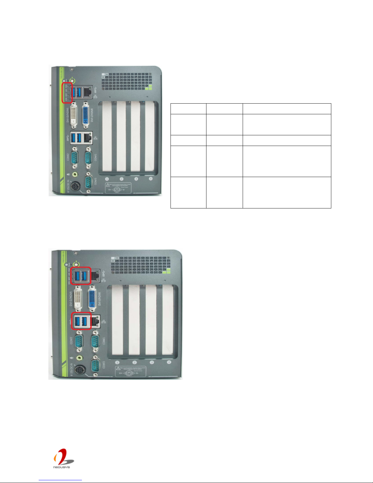
2.2.3 LED Indicators
There are four LED indicators on the front panel:
PWR, UID, WDT and HDD. The descriptions of
these three LED are listed in the following table.
2.2.4 USB 3.0 Connectors
Nuvo-4000 offers four USB 3.0 (SuperSpeed
USB) ports on its front panel. By BIOS
default, these USB ports are operated in
XHCI (eXtensible Host Controller Interface)
mode and are compatible with USB 3.0, USB
2.0, USB 1.1 and USB 1.0 devices. Legacy
USB support is also provided so you can use
USB keyboard/mouse in DOS environment.
USB 3.0 driver is only available for Windows
7 or later version. For Windows XP, please
refer to section 4.1.3 XHCI Support to
disable XHCI mode to avoid poss ible issue of
using USB3 devices in XP.
Indicator
Color
Description
PWR Green Power indictor, l ighted-up
when system is on.
UID Green Reserved for future usage.
WDT
Yellow Watchdog timer indicator,
flashing when watchdog
timer is started.
HDD Red Hard drive indicator,
flashing when SATA HDD
is active.
Page 14
Nuvo-4 0 00 S er i es User’s Man u al
Copyright © 2014 Neousys Technology Inc. All Right Reserved. Page 14 of 76
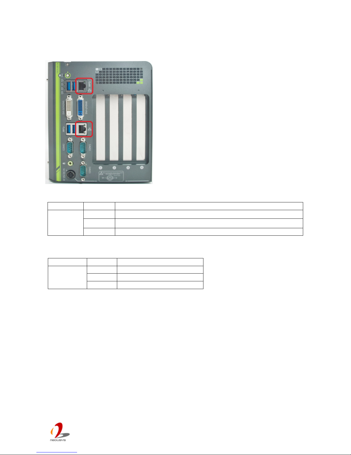
2.2.5 Gigabit Ethernet Port
Nuvo-4000 offers two Gigabit Ethernet ports using
Intel® I210 GbE controller. Each port has one
dedicated GbE controller and one dedicated PCI
Express link to present maximal network
performance. When plugging in the Ethernet cable,
you can tell the Ethernet status and speed from the
LED indicators on the RJ45 connector as following:
Active/Link LED
Speed LED
To utilize the GbE port, you need to install corresponding driver for Intel® I210 GbE
controller. Please refer to section 4.3 for information regarding driver installation.
LED Color
Status
Description
Yellow
Off
Ethernet port is disconnected
On
Ethernet port is connected and no data transmission
Flashing
Ethernet port is connected and data is transmitting or receiving
LED Color
Status
Description
Green or
Orange
Off
10 Mbps
Green
100 Mbps
Orange
1000 Mbps
Page 15
Nuvo-4 0 00 S er i es User’s Man u al
Copyright © 2014 Neousys Technology Inc. All Right Reserved. Page 15 of 76
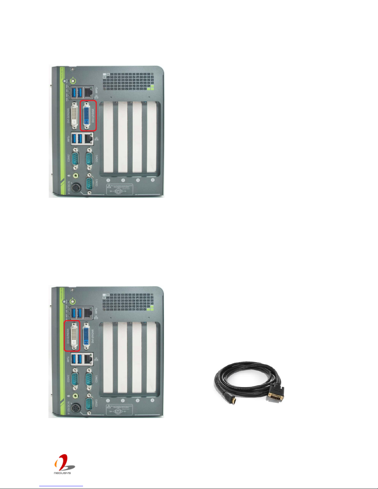
2.2.6 DVI-I Connector
Nuvo-4000 supports triple independent display
outputs via a DVI-I and a DVI-D connector. The
DVI-I connector on the front panel offers DVI/HDMI
and VGA display outputs. The DVI/HDMI outputs
are directly driven by HM76 PCH and support up to
1920 x 1080 resolution. The VGA output is
implemented using an eDP-VGA converter and thus
you need to configure the output resolution (up to
1920 x 1080) according to the display device.
Please refer to section 4.1.5 for inform ation about
configuring VGA output resolution in BIOS. A DVI-I
to DVI+VGA Y-cable is needed to have both VGA
and DVI/HDMI outputs.
The feature of triple independent display outputs is only available in Windows XP/7/8 with
corresponding gra ph ics d r iver ins t a lled. P leas e refe r t o section 4.3 for inf ormation regarding
driver installation.
2.2.7 DVI-D Connector
Nuvo-4000 supports triple independent display
outputs via a DVI-I and a DVI-D connect or. The
DVI-D connector on the front panel offers DVI/HDMI
signal output and supports up to 1920 x 1080
resolution. You shall need a DVI to HDMI cable
when connecting to a HDMI display device.
The feature of triple independent display outputs is only available in Windows XP/7/8 with
corresponding gra ph ics d r iver ins t a lled. P leas e refe r t o section 4.3 for inf ormation regarding
driver installation.
Page 16
Nuvo-4 0 00 S er i es User’s Man u al
Copyright © 2014 Neousys Technology Inc. All Right Reserved. Page 16 of 76
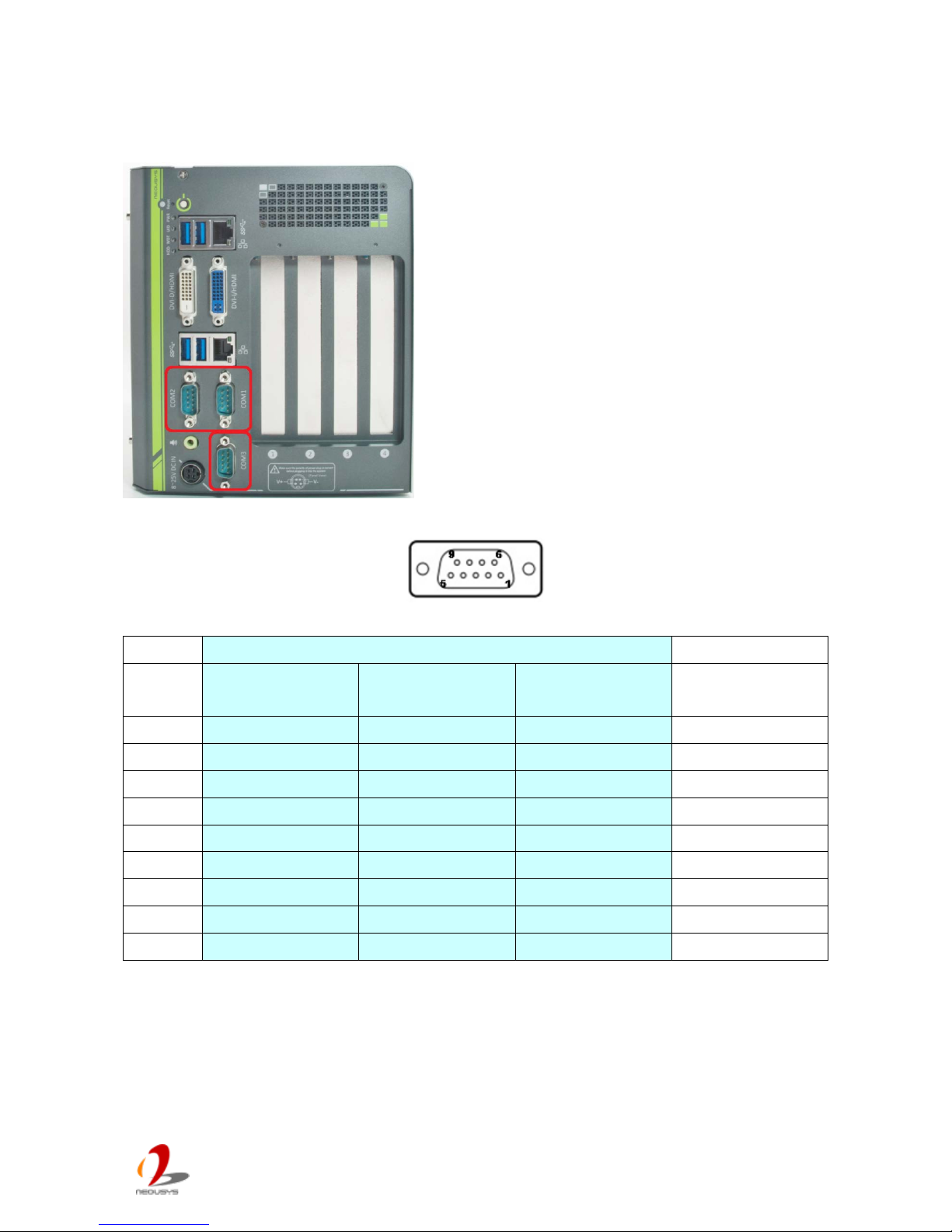
2.2.8 COM Ports
Nuvo-4000 provides three COM ports for
communicating with external dev ices. Thes e COM
ports are implemented using industrial-grade
ITE8783 Super IO ch ip (-40 to 85°C) an d p rov ide up
to 115200 bps baud rate.
COM1 and COM2 are software-selectable
RS-232/422/485 ports and COM3 supports RS-232
only. The operation mode of COM1 and COM2 can
be set in BIOS setup utility (refer to section 4.1.1 for
detail). The following table describes the pin
definition of COM ports.
COM1 & COM2 COM3
Pin# RS-232 Mode RS-422 Mode
RS-485 Mode
(Two-wire 485)
RS-232 Mode
1 DCD DCD
2
RX 422 TXD+ 485 TXD+/RXD+ RX
3 TX 422 RXD+ TX
4
DTR 422 RXD- DTR
5 GND GND GND GND
6
DSR DSR
7 RTS RTS
8
CTS 422 TXD- 485 TXD -/RXD- CTS
9 RI RI
Page 17
Nuvo-4 0 00 S er i es User’s Man u al
Copyright © 2014 Neousys Technology Inc. All Right Reserved. Page 17 of 76
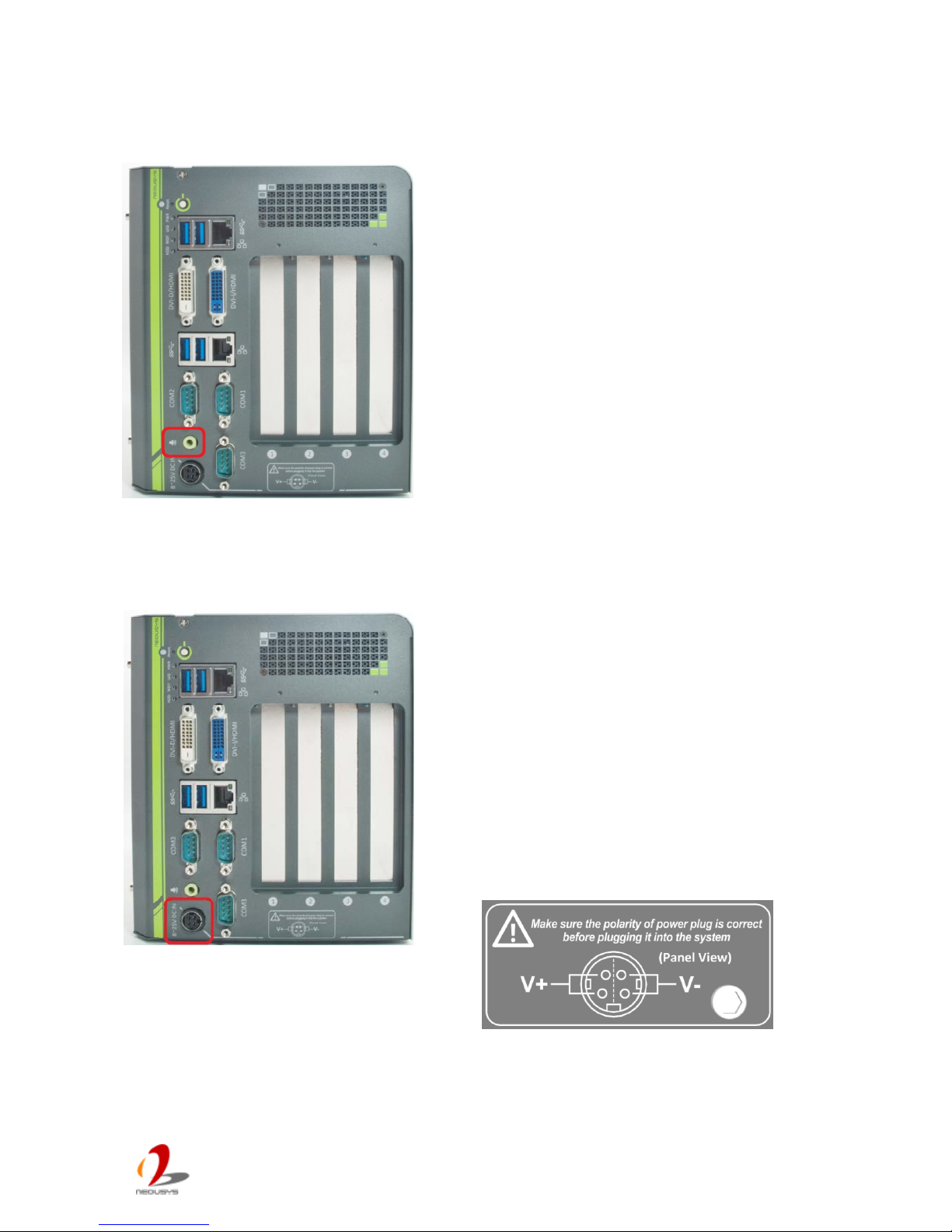
2.2.9 Speaker -Out Jack
Nuvo-4000 provides audio function using Intel®
High Definition Audio (built-in in HM76) and Realtek
ALC262 codec. There is an audio jack available on
the front panel for speaker output. To utilize the
audio function in Windows, you need to install
corresponding drivers for both Intel® HM76 PCH
and Realtek ALC262 codec. Please refer to section
4.3 for information regarding driver insta llat ion .
2.2.10 4-Pin Mini-DIN Power Connector
Nuvo-4000 allows a wide range of DC power input
from 8 to 25V. The 4-pin mini-DIN power connector
on the front panel is used to connect the power plug
of an AC/DC adapter. It’s convenient for indoor
usage where AC power is usually available. Since
there is no specific rule of pin definition for this type
of connector, please always confirm the polarity of
the power connector in prior to plug it into
Nuvo-4000 if you’re not using the power adapter
provided from Neousys.
Caution
1. Please make sure the voltage of DC power is correct before you connect it to Nuvo-4000.
Supplying a voltage over 25V will damage the system.
Page 18
Nuvo-4 0 00 S er i es User’s Man u al
Copyright © 2014 Neousys Technology Inc. All Right Reserved. Page 18 of 76
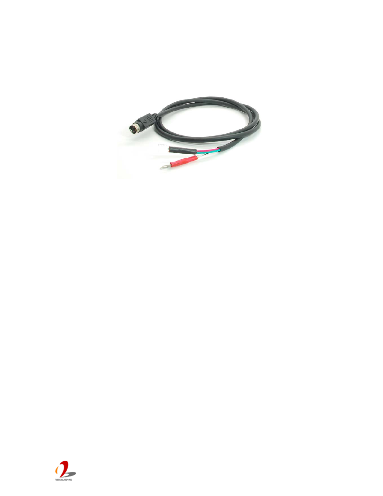
Neousys also offers a n opt iona l power c ab le for the dep loyment where DC is availab le. You
can wire the cable to DC power source (red for V+, black for GND) and connect the power
plug to the 4-pin mini-DIN connector on Nuvo-4000.
Page 19
Nuvo-4 0 00 S er i es User’s Man u al
Copyright © 2014 Neousys Technology Inc. All Right Reserved. Page 19 of 76
2.3 Internal I/O Functions
In addition to I/O connectors on the front panel, Nuvo-4000 provides more useful features
via its on-board connectors, such as remote on/off control, LED status output, internal USB
2.0 ports, CFast and etc. In this section, we’ll illustrate these internal I/O functions.
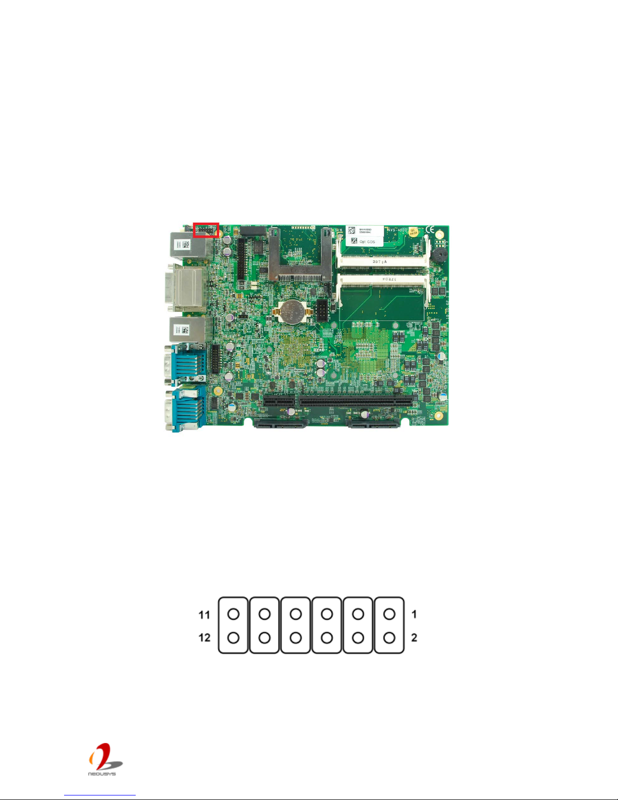
2.3.1 Status LED Output & Remote On/Off Control
For an application w hich places Nuvo-4000 inside a cabinet, it’ s usefu l to outp ut the sy stem
status to external LED indicators so that users can check how the system’s running.
Nuvo-4000 provides a 2x6, 2.0mm pitch pin header to output system status such as power,
HDD, watchdog timer, and control system on/off remotely.
The status LED output has a built-in series-resistor and provides 10mA current to directly
drive the external LED indicators. System on/off control is also provided so you can use an
external non-latched switch to turn on/off the system exactly the same as the power button
on the front panel. The following table describes the pin definition of the status LED output.
Page 20
Nuvo-4 0 00 S er i es User’s Man u al
Copyright © 2014 Neousys Technology Inc. All Right Reserved. Page 20 of 76
Pin# Definition Description
1
WDT_LED-
[Output] Watchdog timer indicator, flashing when
watchdog timer is started.
2 WDT_LED+
3
UID_LED-
[Output] User defined LED, reserved for future usage
4 UID_LED+
5
HDD-
[Output]
Hard drive indicator, flashing when SATA hard
drive is active.
6 HDD+
7
Power_LED-
[Output]System power indicator, on if system is turned
on, off if system is turned off.
8 Power_LED+
9
Ctrl-
[Input] Remote on/off control, connecting to an external
switch to turn on/off the system. (polarity is negligible).
10 Ctrl+
11
NA
Un-used pin
12 NA
Note
Please make sure the polarity is correct when you connect the external LED indicator to the Status
LED Output.
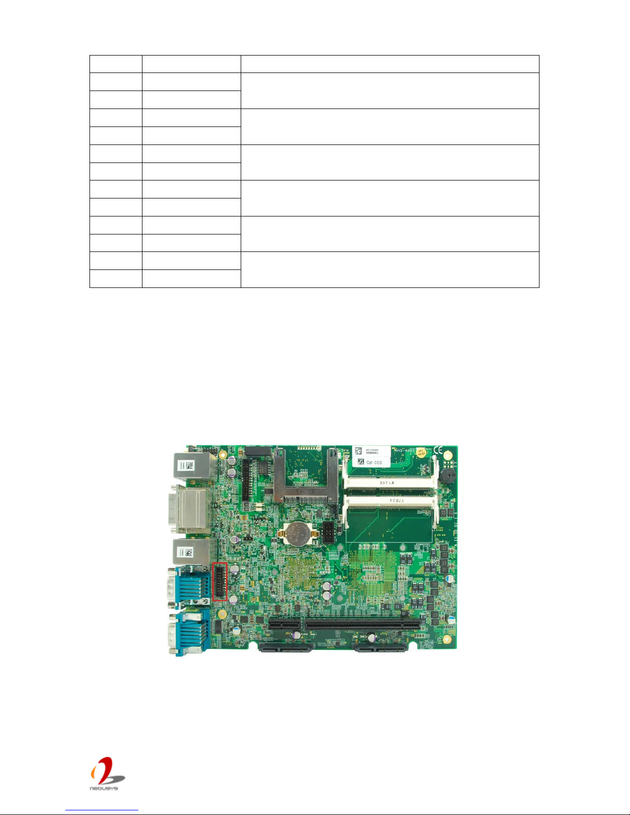
2.3.2 Internal USB2.0 Pin Header
Nuvo-4000 provides additiona l tw o USB 2.0 port s in terna lly v ia a 2x8 pins, 2.0mm pitch box
header. The internal USB ports are designed to allow users attaching a protection dongle
inside the chassis. To use the internal USB port, you need a dedicated box-header to USB
cable. Please contact Neousys for further information
Page 21
Nuvo-4 0 00 S er i es User’s Man u al
Copyright © 2014 Neousys Technology Inc. All Right Reserved. Page 21 of 76
1
2
16 15
Pin#
Pin Definition
1
USB 5V Power, Max 500mA
2 USB 5V Power, Max 500mA
3
USB8 D-
4 USB9 D-
5
USB8 D+
6 USB9 D+
7
Ground
8 Ground
9 ~ 16
N/C
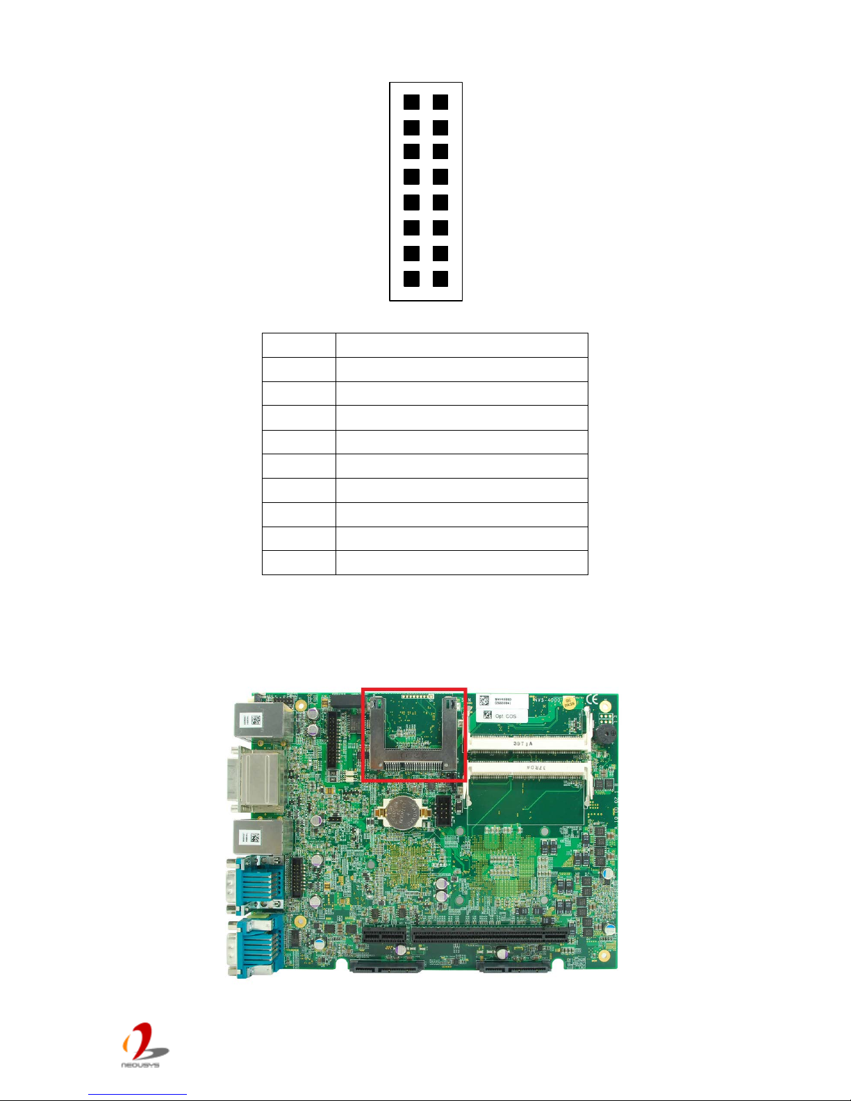
2.3.3 CFast Socket
Page 22
Nuvo-4 0 00 S er i es User’s Man u al
Copyright © 2014 Neousys Technology Inc. All Right Reserved. Page 22 of 76
Nuvo-4000 provides a CFast socket on its SBC. CFast is a new interface for portable
storage device. It shares a similar form-factor as CompactFlash but leverages Serial ATA
interface to offer higher data transfer rate. The CFast socket on Nuvo-4000 is a push-push
type. You can insert and push a CFast card to the end to instal l it, and push the installed
CFast card again to eject it.
2.3.4 DDR3 SODIMM Socket
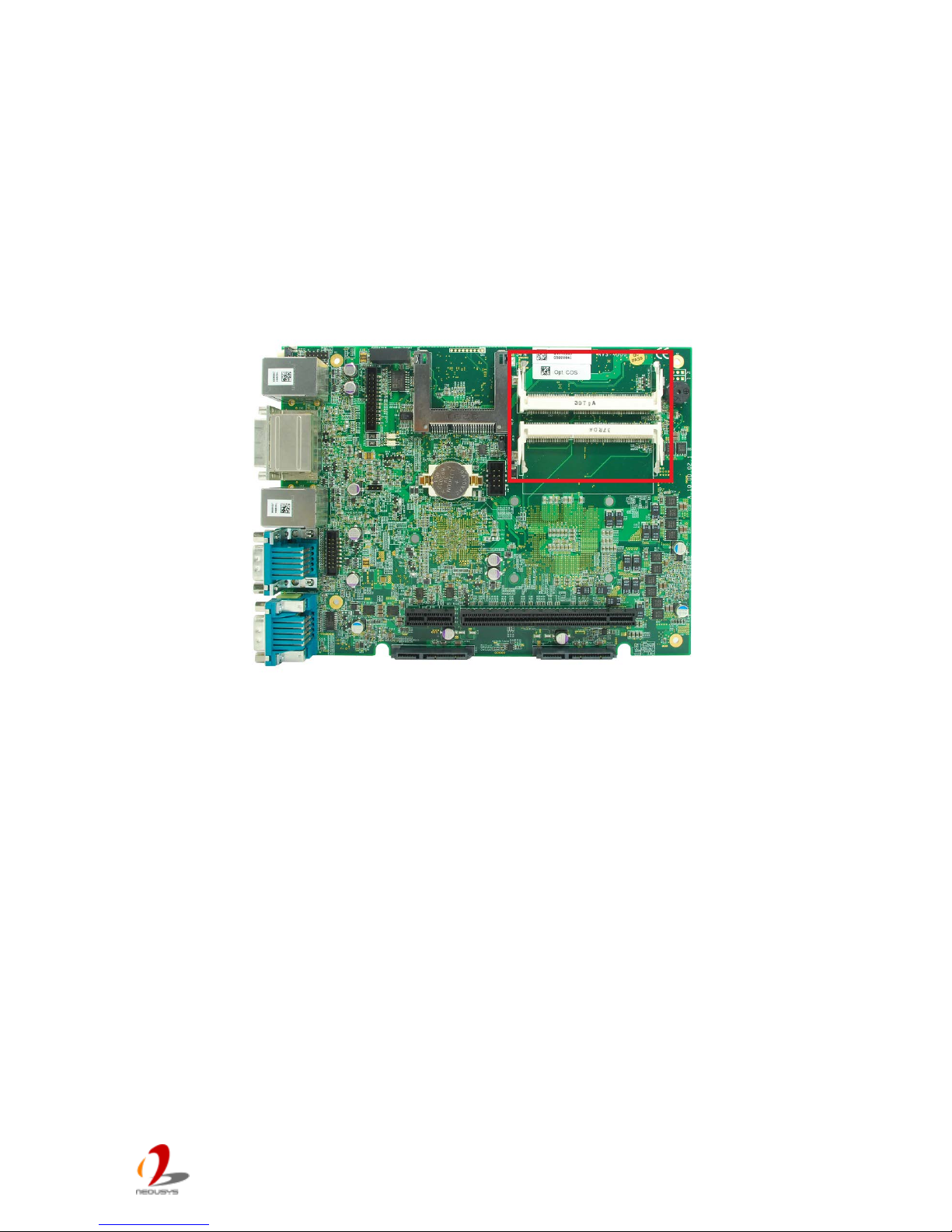
Nuvo-4000 provides two 204-pin, SODIMM sockets for insta l ling DDR3 memory m odules. I t
supports a maximal 16GB capacity by installing two 8GB DDR3 1600MHz SODIMM
modules. For information of installing DDR3 memory modules, please refer to section 3.3
for detail.
Page 23
Nuvo-4 0 00 S er i es User’s Man u al
Copyright © 2014 Neousys Technology Inc. All Right Reserved. Page 23 of 76
2.3.5 SATA Connectors
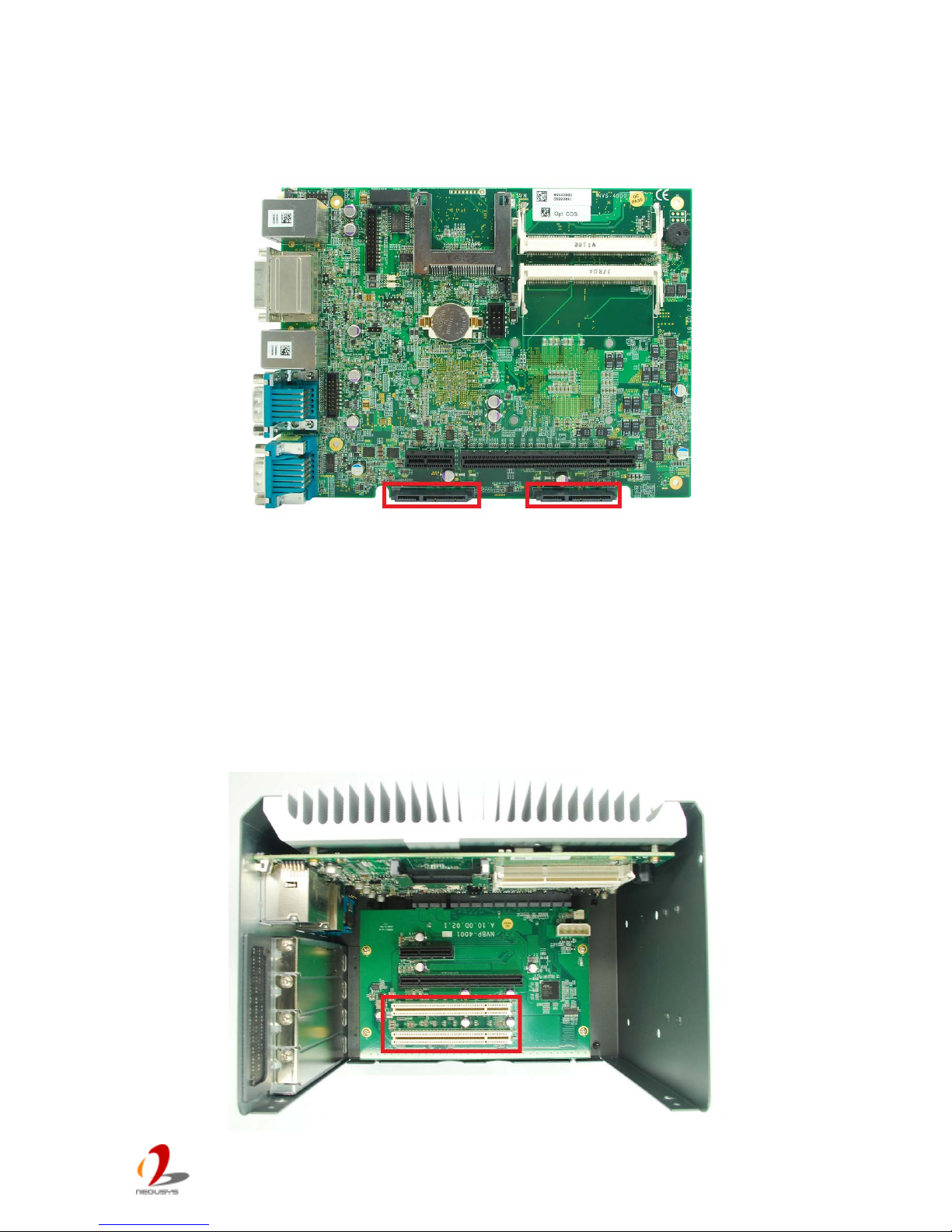
Nuvo-4000 provides two SATA ports to accommodate two 2.5” SATA hard drives in its
chassis. These SATA ports are located on the SBC via two 22-pin SATA connectors. With
the HDD bracket shipped with Nuvo-4000, you can directly mount two 2.5” HDDs/SSDs to
these ports. For information of installing HDD/SSD to the SA TA port, please ref er to sect ion
3.1 for detail.
2.3.6 PCI Slots
Page 24
Nuvo-4 0 00 S er i es User’s Man u al
Copyright © 2014 Neousys Technology Inc. All Right Reserved. Page 24 of 76
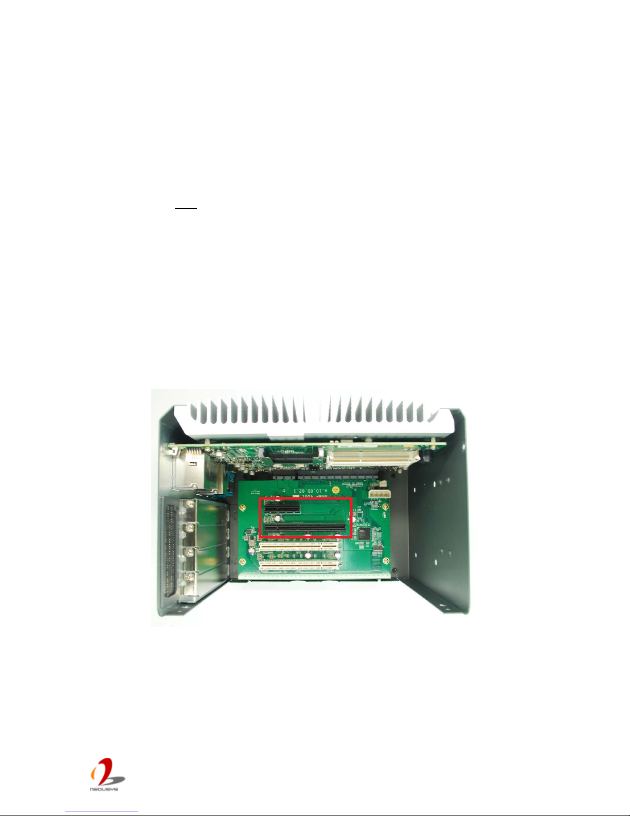
PCI slots are located on the backplane of Nuvo-4000. Nuvo-4022 provides two PCI slots,
and Nuvo-4040 provides four PCI slots. These PCI slots support 5V, 32-bit/33MHz PCI bus
and can accommodate the PCI card with a maximal dimension of 205mm x 105mm (PCB
size, excluding connector). For information of installing PCI cards, please refer to section
3.4 for detail.
Note
1. Due to the fanless feature, th e total po w er c on sumption of instal led PCI and PCIe car ds should
be confin ed to 16W to limit the heat generated by add-on cards and maintain the system
stability. For applications need add-on cards with higher power consumption, the fan option is
suggested to maintain a reasonable temperature inside the chassis. Please contact Neousys
Technology for th e fan o pti o n.
2. The operating temperature of the whole system when cards installed is affected by the power
consumption and operating temperature of add-on cards. Please consult your add-on card
dealer or Neousys Technology for further information.
2.3.7 PCI Express Slots (Nuvo-4022 Only)
Nuvo-4022 provides one x4 and one x16 PCI Express slot. As each PCI Express lane
delivers 500 MB/s bandwidth, its x4 PC I Exp res s slo t delivers 2 GB/s bandwi dth and x16
slot delivers 4 GB/s bandwidth*. In addition, a dedicated 48W (4A@12V) power rail is
supplied to the x16 PCI Express slot for powering a high-watt PCIe card (e.g. a graphics
card). Another 48W (4A@12V) power rail is shared by x4 PCIe Express slot and other
peripheral devices.
Page 25

Nuvo-4 0 00 S er i es User’s Man u al
Copyright © 2014 Neousys Technology Inc. All Right Reserved. Page 25 of 76
These slots can accommodate PCIe card with a maximal dimension of 205mm x 105mm
(PCB size, excluding connector). For information of installing PCIe cards, please refer to
section 3.4 for detail.
*The x16 PCIe slot on Nuvo-4022 is implemented with 8-la nes, Gen2 PCI Expr ess link an d del iv er s
4GB/s bandwidth. You can install a x16, x8, x4 or x1 PCI Express add-on card to the x16 slot.
Note
1. Due to the fanless feature, th e total po w er c on sumption of instal led PCI and PCIe car ds should
be confin ed to 16W to limit the heat generated by add-on cards and maintain the system
stability. For applications need add-on cards which consume more than 16W, the fan option is
suggested to maintain a reasonable temperature inside the chassis. Please contact Neousys
Technology for th e fan o pti o n.
2. The operating temperature of the whole system when cards installed is affected by the power
consumption and operating temperature of add-on cards. Please consult your add-on card
dealer or Neousys Technology for further information.
Page 26
Nuvo-4 0 00 S er i es User’s Man u al
Copyright © 2014 Neousys Technology Inc. All Right Reserved. Page 26 of 76
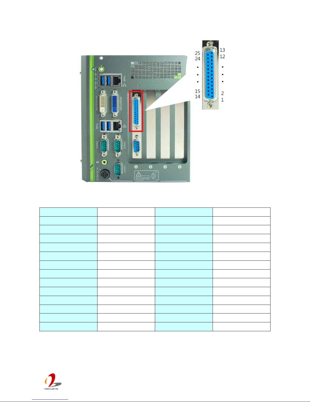
2.3.8 Optional Isolated DIO
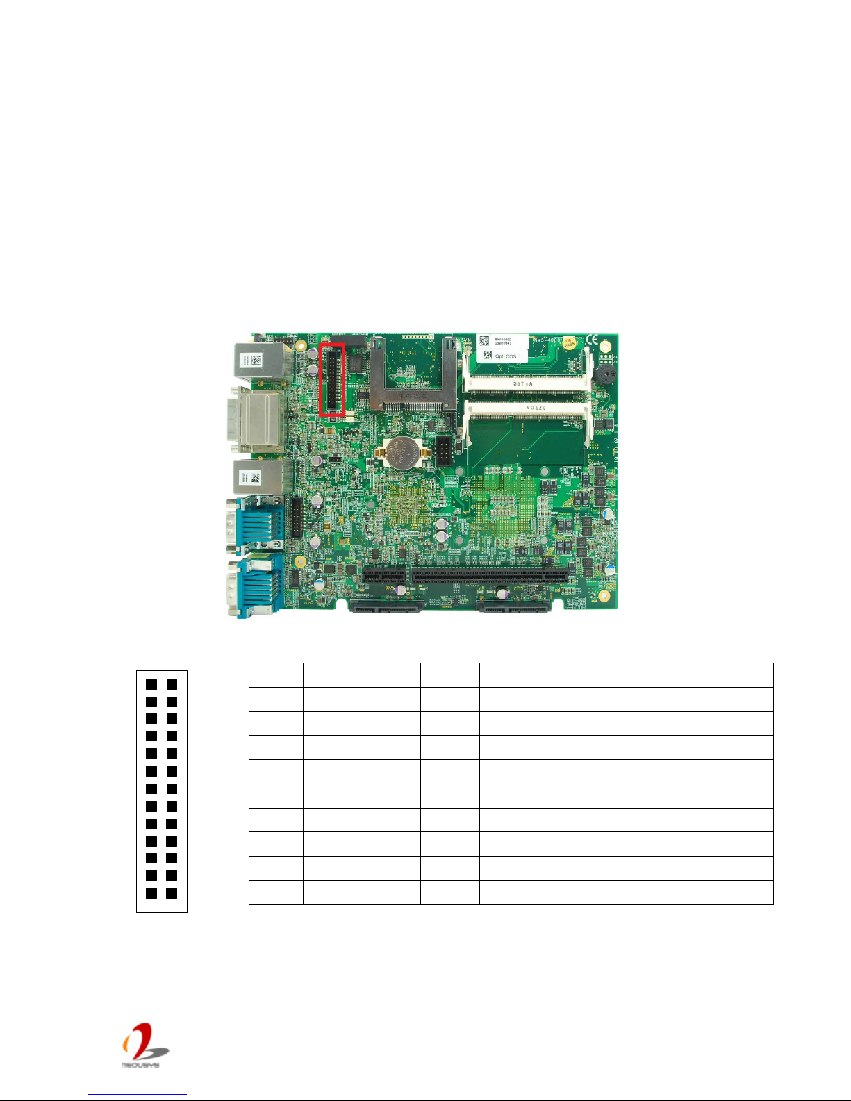
Nuvo-4000 offers an option of on-board 2500 Vrms isolated DIO for extending application
range. This option provides 8 channels of isolated digital input and 8 channels of isolated
digital output via an on-b oard 2x 13 p ins box header. Neousys also provides a flat cab le and
DSub 25-pin connector to allow front-panel access for the DIO function. In prior to use the
DIO function, you need to install Neousys WDT_DIO driver package. Please refer to
Appendix A for information of using DIO function.
1
2
2625
DIO Connector (box-header) on main board
Pin#
Pin Definition
Pin#
Pin Definition
Pin#
Pin Definition
1 VDD 2 Isolation 5V 3 D_OUT_0
4 DO _GND 5 D_OUT_3 6 D_OUT_1
7 DO _GND 8 D_OUT_2 9 D_OUT_5
10 D_OUT_4 11 D_OUT_7 12 D_OUT_6
13 DI_GND 14 DO_GND 15 D_IN_6
16 DI_GND 17 D_IN_1 18 D_IN_5
19 DI_GND 20 D_IN_3 21 D_IN_0
22
D_IN_7
23
D_IN_2
24
DI_GND
25 D_IN_4 26 N/C
Page 27
Nuvo-4 0 00 S er i es User’s Man u al
Copyright © 2014 Neousys Technology Inc. All Right Reserved. Page 27 of 76
DIO Connector (DSub-25) on the front panel
Pin#
Pin Definition
Pin#
Pin Definition
1
VDD
14
ISO_5V
2 DO_0 15 DO_GND
3
DO_3
16
DO_1
4 DO_GND 17 DO_2
5
DO_5
18
DO_4
6 DO_7 19 DO_6
7
DI_GND
20
DO_GND
8 DI_6 21 DI_GND
9
DI_1
22
DI_5
10 DI_GND 23 DI_3
11
DI_0
24
DI_7
12 DI_2 25 DI_GND
13
DI_4
Page 28
Nuvo-4 0 00 S er i es User’s Man u al
Copyright © 2014 Neousys Technology Inc. All Right Reserved. Page 28 of 76
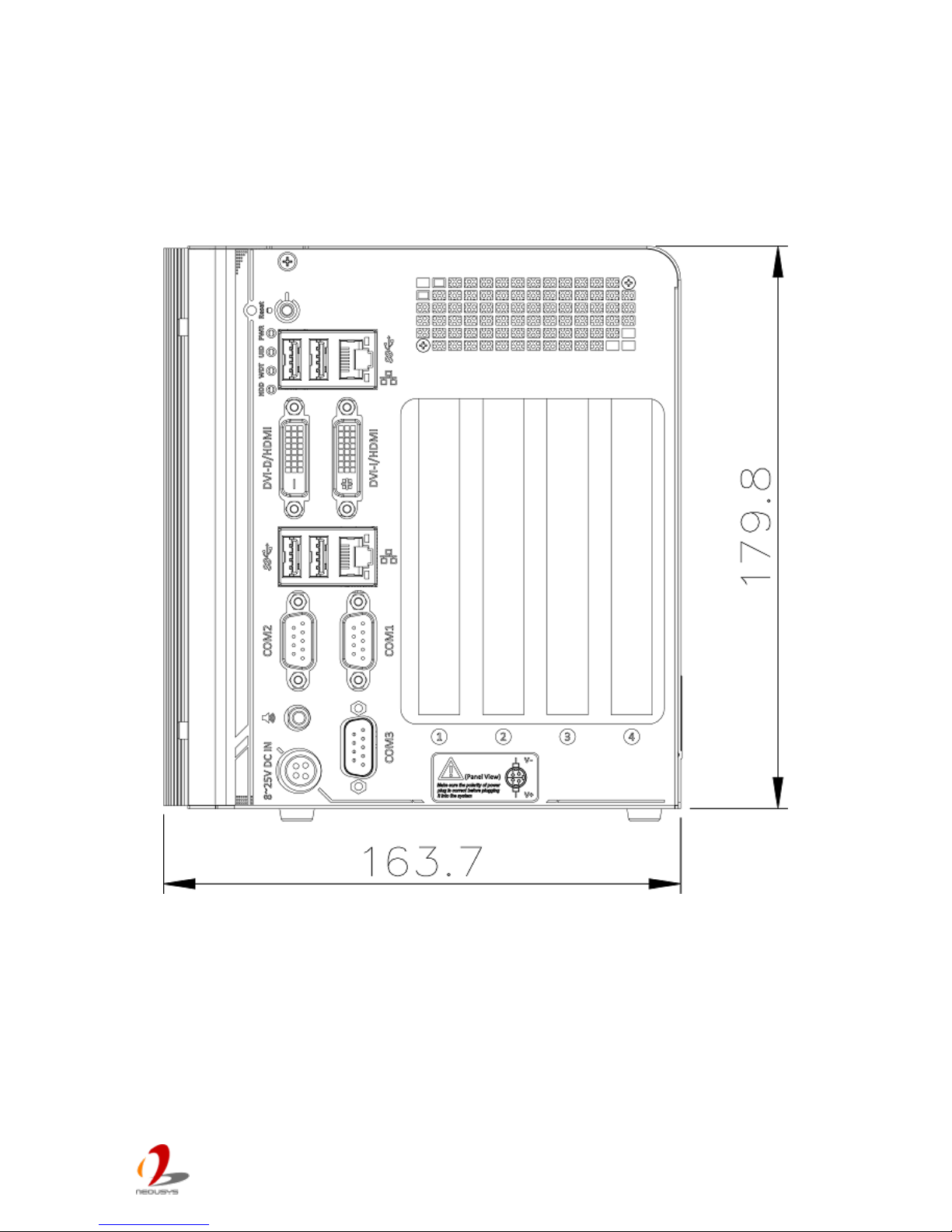
2.4 Mechanical Dimension
2.4.1 Front Vie w
Page 29
Nuvo-4 0 00 S er i es User’s Man u al
Copyright © 2014 Neousys Technology Inc. All Right Reserved. Page 29 of 76
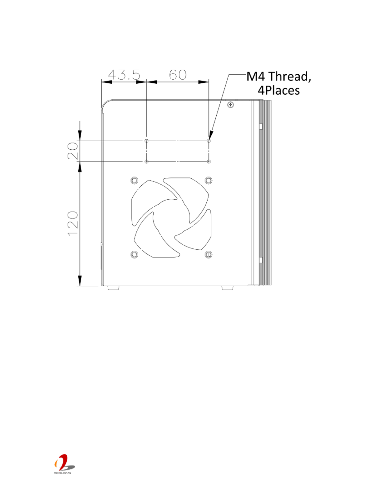
2.4.2 Back Vie w
Page 30
Nuvo-4 0 00 S er i es User’s Man u al
Copyright © 2014 Neousys Technology Inc. All Right Reserved. Page 30 of 76
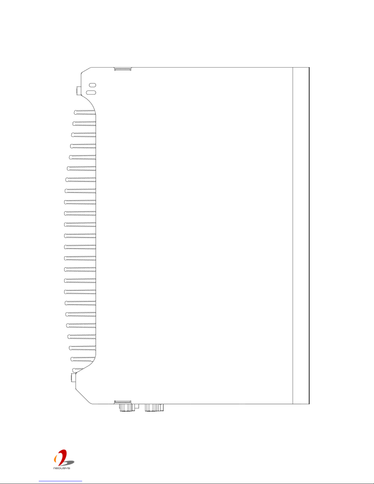
2.4.3 Top View
Page 31
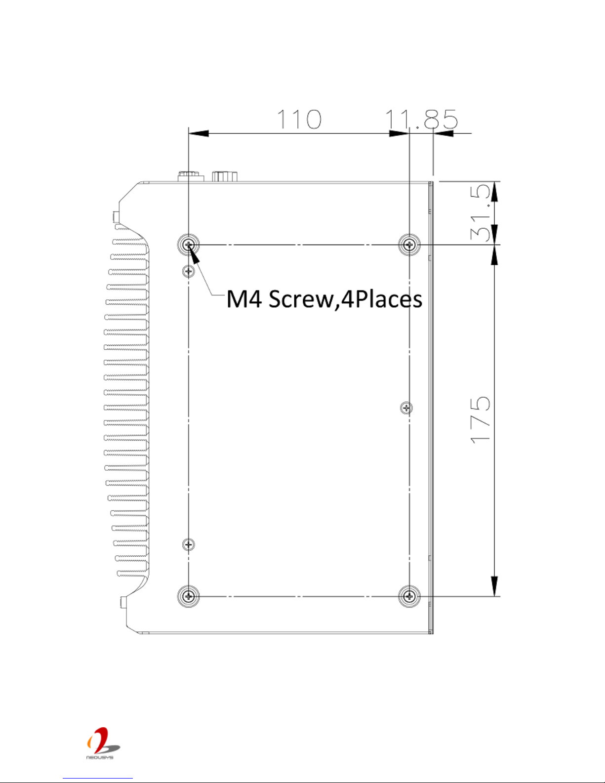
Nuvo-4 0 00 S er i es User’s Man u al
Copyright © 2014 Neousys Technology Inc. All Right Reserved. Page 31 of 76
2.4.4 Bottom View
Page 32
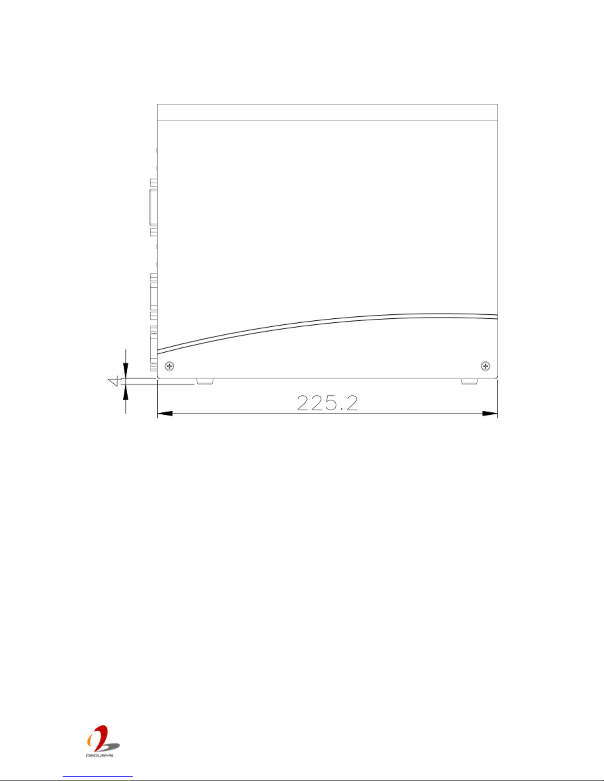
Nuvo-4 0 00 S er i es User’s Man u al
Copyright © 2014 Neousys Technology Inc. All Right Reserved. Page 32 of 76
2.4.5 Right View
Page 33
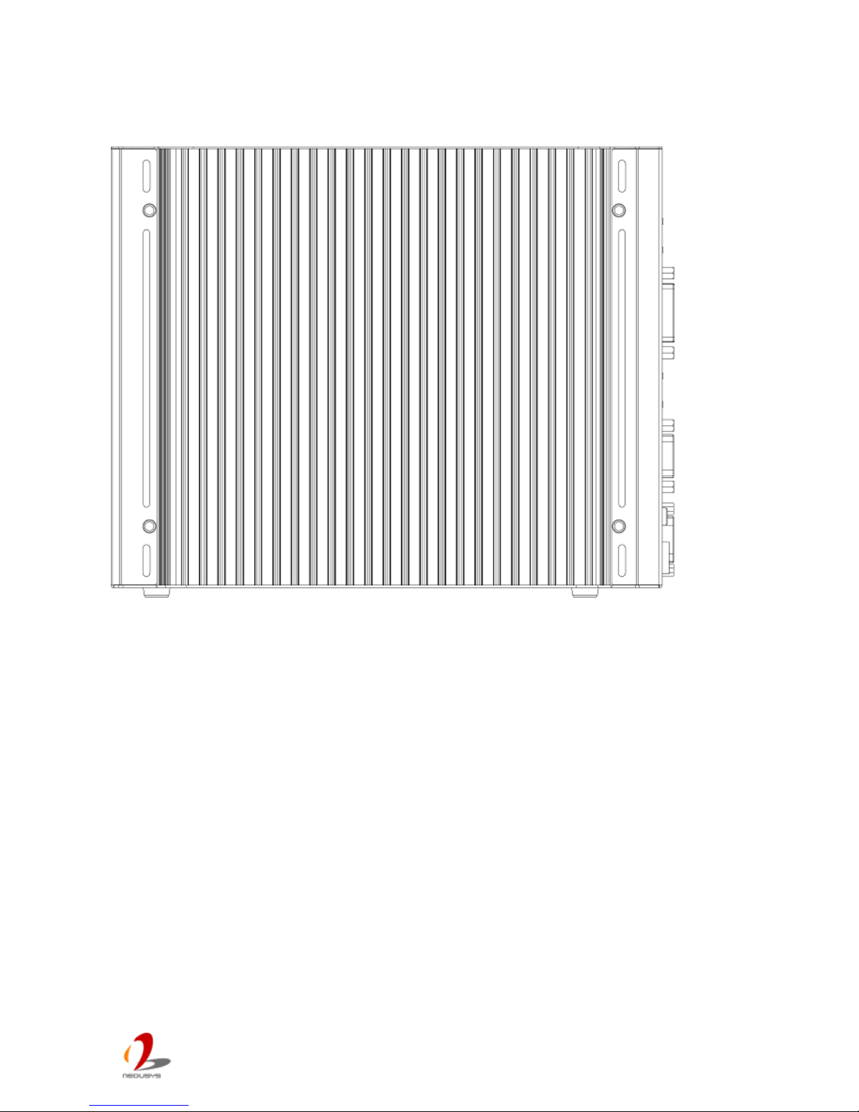
Nuvo-4 0 00 S er i es User’s Man u al
Copyright © 2014 Neousys Technology Inc. All Right Reserved. Page 33 of 76
2.4.6 Left V iew
Page 34
Nuvo-4 0 00 S er i es User’s Man u al
Copyright © 2014 Neousys Technology Inc. All Right Reserved. Page 34 of 76
Chapter 3 Getting Start
3.1 Insta ll the SATA HDD/SSD
Nuvo-4000 offers two SATA por ts located on the SBC via two 22-pin SATA connectors. A
dedicated bracket is included in its chassis assembly to hold two HDDs and connect them
to SATA ports. To install HDD(s) on SATA port(s), please follow the steps listed below.
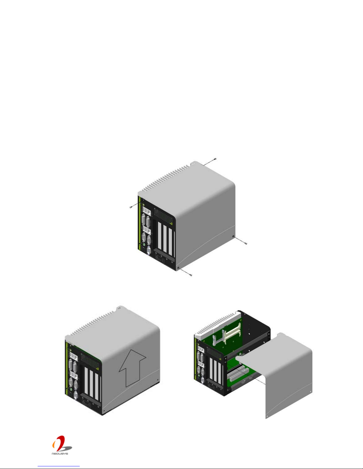
1. Loose 4 screws on the front, back and right side of the chassis.
2. Simply open the chassis by pushing its side cover toward top, then remove the side
cover and the SBC is exposed.
Page 35
Nuvo-4 0 00 S er i es User’s Man u al
Copyright © 2014 Neousys Technology Inc. All Right Reserved. Page 35 of 76
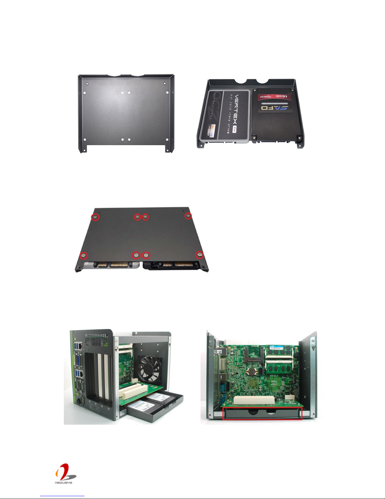
3. Get the HDD bracket and eight M3 flat-head screws from the accessory box. And
install your HDD(s) into the HDD bracket. Note that the HDD must be placed in a right
direction.
4. Fasten the HDD(s) using M3 flat-head screws.
5. Smoothly push the HDD bracket assembly into the SATA slot at the bottom of
Nuvo-4000 case until SATA HDD(s) firmly attached to SATA connector(s).
Page 36
Nuvo-4 0 00 S er i es User’s Man u al
Copyright © 2014 Neousys Technology Inc. All Right Reserved. Page 36 of 76
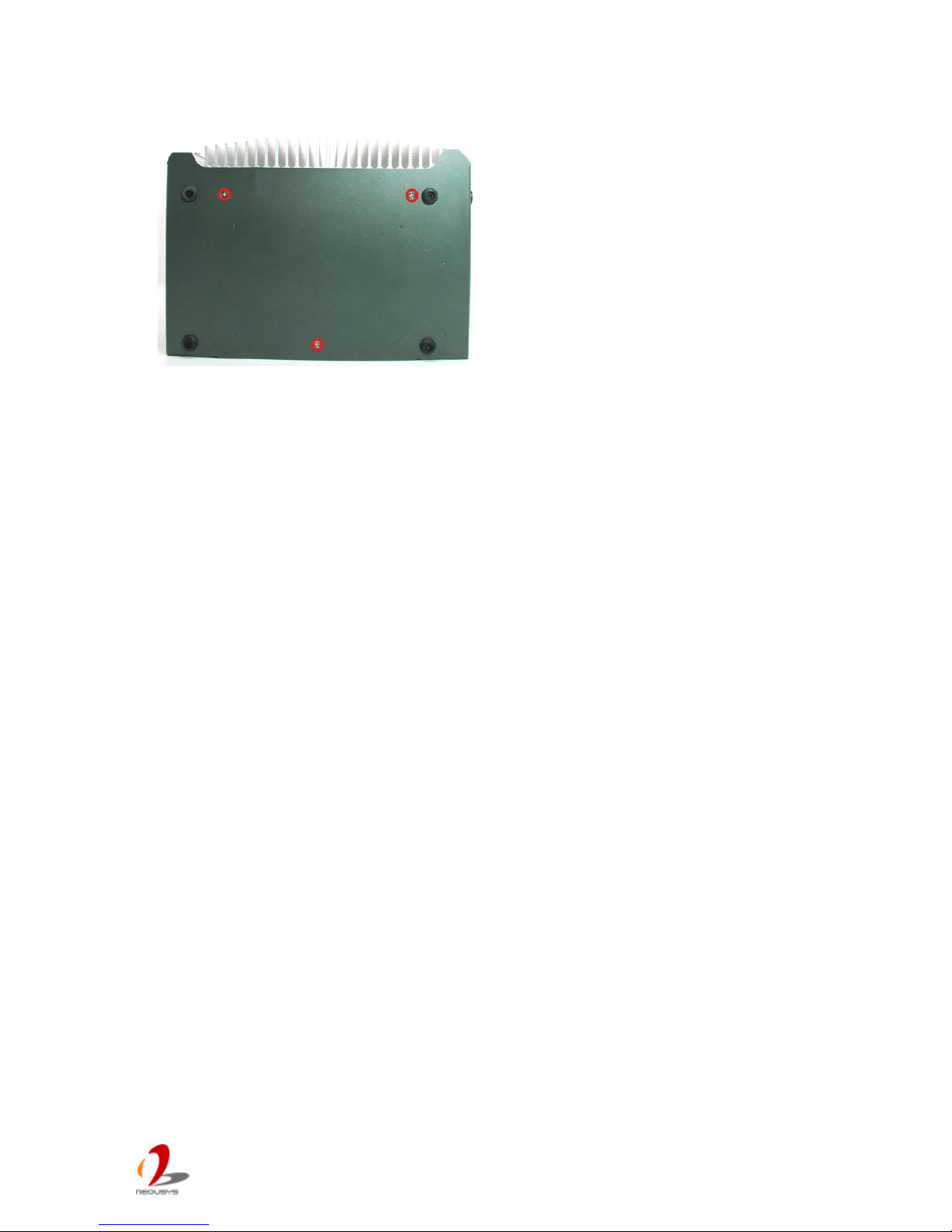
6. Fix the SATA HDD bracket to the bottom of chassis with three M3 flat-head screws.
Page 37
Nuvo-4 0 00 S er i es User’s Man u al
Copyright © 2014 Neousys Technology Inc. All Right Reserved. Page 37 of 76
3.2 Install a CFast card
Nuvo-4000 provides an on-board CFast socket. The CFast socket is directly connected to
the SATA port of HM76 chipset and accordingly you can use a CFast card for installing
operating system such as Windows XP, Windows 7, Linux and etc. To install a CFast card,
please follow the steps listed below.
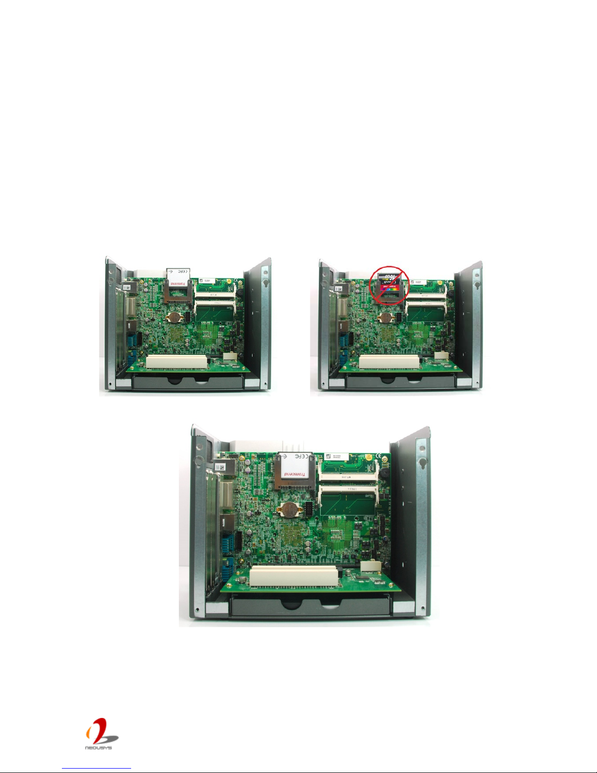
1. Open the chassis by following step #1 and #2 in section 3.1. You can see the CFast
socket exposed.
2. Align your CFast card with the guide of the CFast socket. Note that you must have the
obverse side toward the SBC.
3. Push down your CFast card until it’s firmly contacted with pins of the CFast socket.
Page 38
Nuvo-4 0 00 S er i es User’s Man u al
Copyright © 2014 Neousys Technology Inc. All Right Reserved. Page 38 of 76
3.3 Insta ll the DDR3 SODIMM Module
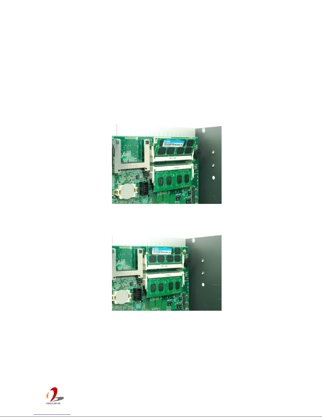
Nuvo-4000 provides two 204-pin, SODIMM sockets for installing DDR3 memory module(s).
It supports maximal two 8GB, 1333/1600MHz DDR3 SODIMM modules. To install the
DDR3 SODIMM module, please follow the steps listed below.
1. Open the chassis by follow ing step #1 an d #2 in sect ion 3.1. Th e S ODIM M soc ket s are
exposed.
2. Tile the SODIMM module and insert it to the SODIMM socket on the SBC.
3. As the DDR3 SODIMM module is firmly contacted with socket connectors, press it
down until the clam p s of t he socket s nap into the latc hing pos it ion of SODIM M m odule.
4. Repeat step#2 and step#3 if you want install second DDR3 SODIMM module.
Page 39
Nuvo-4 0 00 S er i es User’s Man u al
Copyright © 2014 Neousys Technology Inc. All Right Reserved. Page 39 of 76
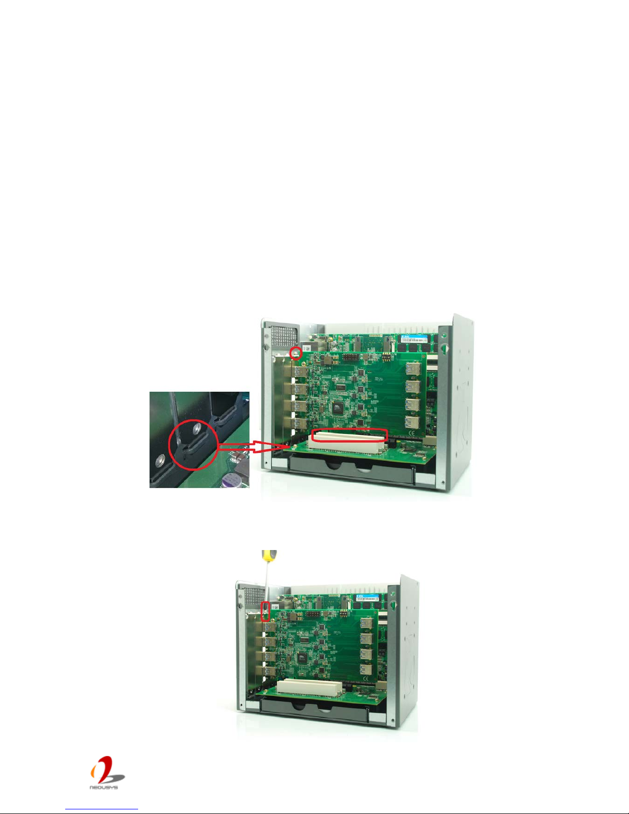
3.4 Insta ll the PCI/PCIe Add-on Card
Nuvo-4000 provides PCI and PCIe slots on its backplane. Nuvo-4040 provides four PCI
slots, as Nuvo-4022 provides two PCI slots plus two PCI Express slots. Nuvo-4000
supports 5V, 33MHz/32-bit PCI bus and can accommodate PCI cards with a maximal
dimension of 205mm x 105mm (PCB size, excluding connector).
To install the PCI/PCIe add-on card, please follow the steps listed below.
1. Open the chassis by following step #1 and #2 in section 3.1. The PCI/PCIe slots are
exposed.
2. Install your add-on card into the PCI/PCIe slot. Make sure the “golden finger”
connector is firmly contacted with PCI/PCIe connector and the faceplate of the add-on
card is well inserted to the groove underneath.
3. Get the M3 PW-head screw from the accessory box. And use it to fix your PCI/PCIe
add-on card.
Page 40
Nuvo-4 0 00 S er i es User’s Man u al
Copyright © 2014 Neousys Technology Inc. All Right Reserved. Page 40 of 76
3.5 Mount your Nuvo-4000
Nuvo-4000 provides versatile ways of mounting. You can use wall-mounting brackets
shipped with Nuvo-4000 to mount it on the wall. Neousys also of fe rs opt iona l DIN rail clip to
mount Nuvo-4000 on a DIN rail. To mount your Nuvo-4000, please refer to the information
listed below.
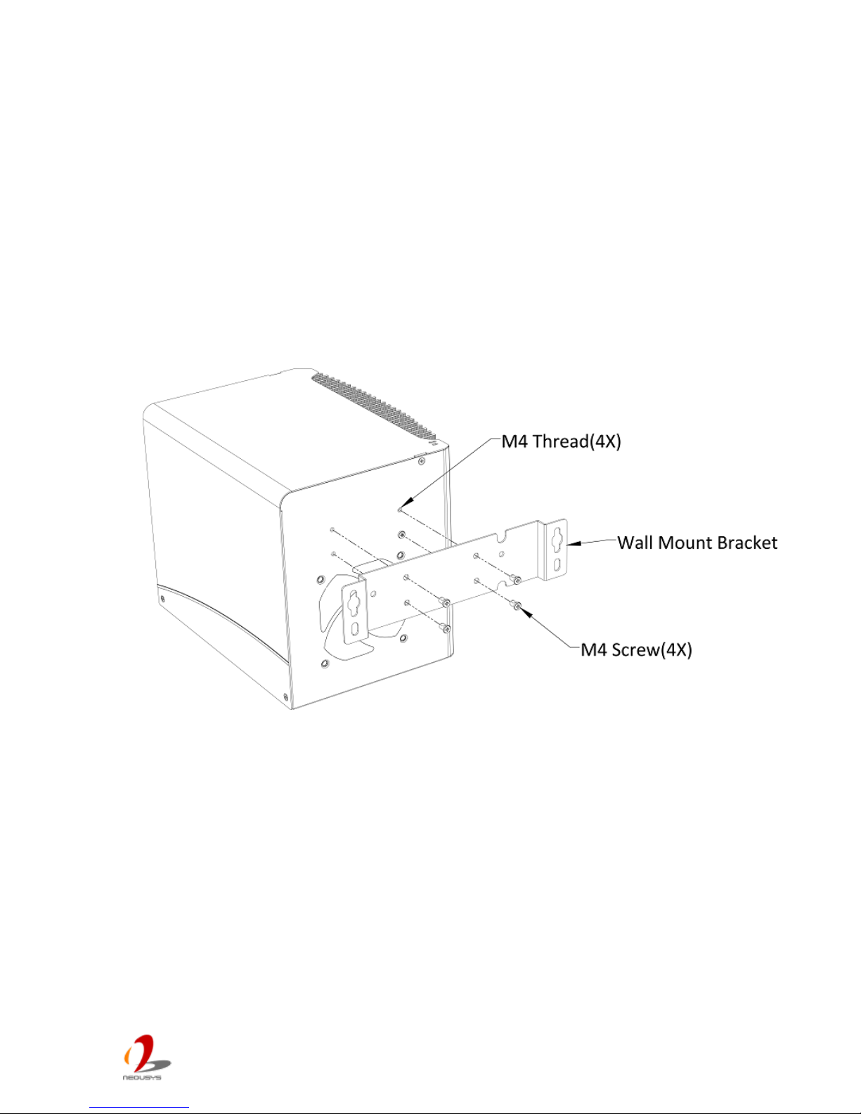
3.5.1 Mount your Nuvo-4000 on the Wall
1. Get one wall-mounting bracket and four M4 screws from the accessory box. Fix the
mounting bracket to the back side of Nuvo-4000 using M4 screws.
Page 41
Nuvo-4 0 00 S er i es User’s Man u al
Copyright © 2014 Neousys Technology Inc. All Right Reserved. Page 41 of 76
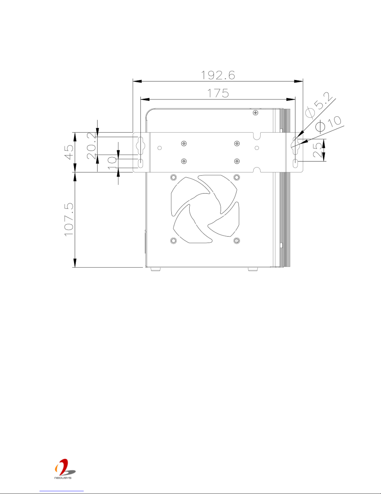
2. Fix Nuvo-4000 on the wall via the screw holes of the mounting bracket. You can also
take advantage of the keyhole-shaped holes of the mounting bracket to suspend
Nuvo-4000 on the Wall.
Page 42
Nuvo-4 0 00 S er i es User’s Man u al
Copyright © 2014 Neousys Technology Inc. All Right Reserved. Page 42 of 76
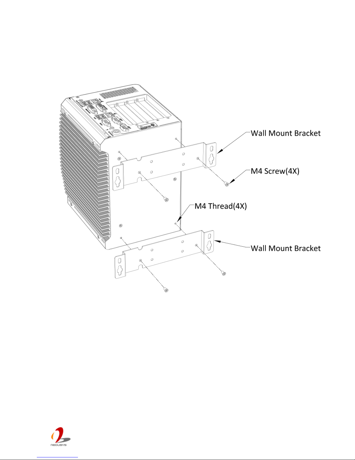
3.5.2 Mount your Nuvo-4000 on a Flat Surface
1. Get two wall-mounting brackets and four M4 screws from the accessory box. Fix the
mounting brackets to the bottom side of Nuvo-4000 using M4 screws.
Page 43
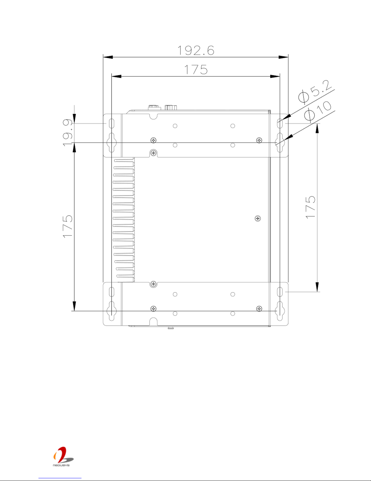
Nuvo-4 0 00 S er i es User’s Man u al
Copyright © 2014 Neousys Technology Inc. All Right Reserved. Page 43 of 76
2. Fix Nuvo-4000 on a flat surface via the screw holes of two mounting brackets.
Page 44
Nuvo-4 0 00 S er i es User’s Man u al
Copyright © 2014 Neousys Technology Inc. All Right Reserved. Page 44 of 76
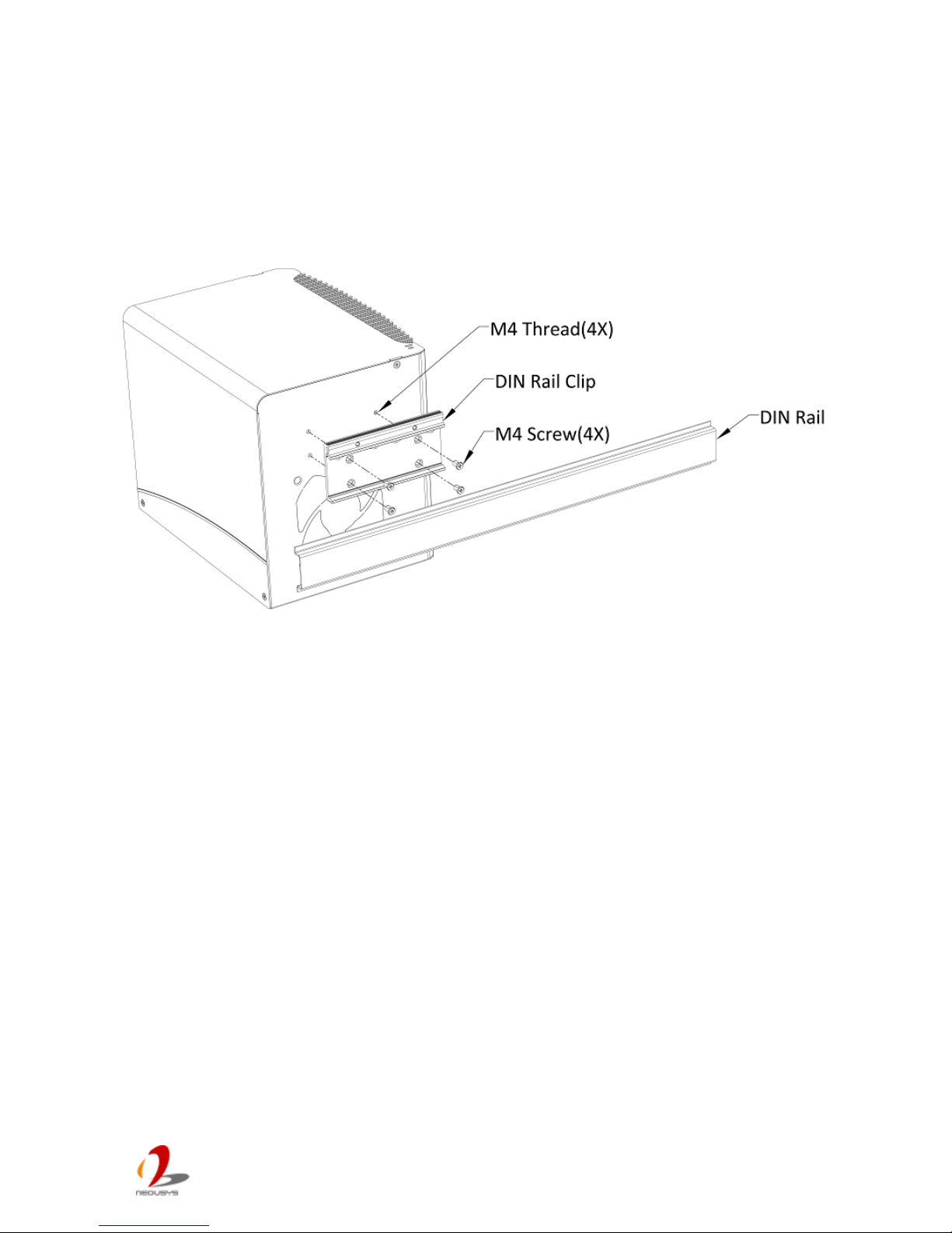
3.5.3 Mount your Nuvo-4000 on the DIN Rail
Neousys also provides the option of the DIN-rail mounting clip. You should fix the clip to
Nuvo-4000 using four M4 flat-head screws before mount it to a DIN rail. This option can be
useful if you want to deploy Nuvo-4000 inside an equipment cabinet where DIN rail is
available.
Page 45
Nuvo-4 0 00 S er i es User’s Man u al
Copyright © 2014 Neousys Technology Inc. All Right Reserved. Page 45 of 76
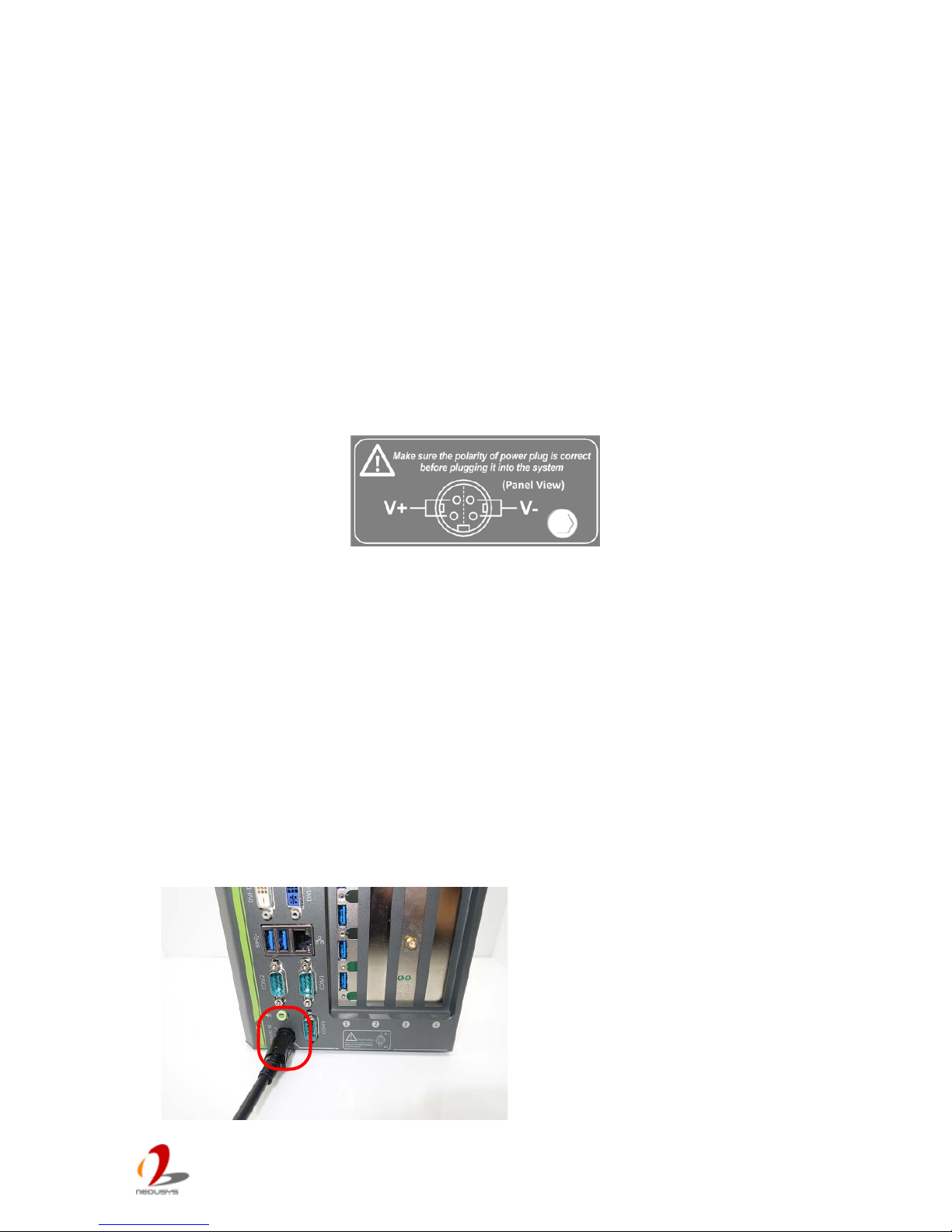
3.6 Connect DC power to you Nuvo-4000
Nuvo-4000 can be powered by 8~25V DC via the 4-pin mini-DIN power connector on the
front panel. Neousys provides a matched AC/DC power adapter (for where AC is ava ilab le)
and an option of 4-pin mini-DIN power cable (for where DC is available) for powering your
Nuvo-4000.
Caution
1. Please make sure the voltage of DC power is correct before you connect it to Nuvo-4000.
Supplying a voltage over 25V will dam a ge th e system.
2. Please always confirm the polarity of the power connector in prior to plug it into Nuvo-4000 if
you’re not using the power adapter provided from Neousys.
To connect DC power via the 4 -pin mini-DIN p ow er connect or, p lease fo l low t he steps l isted
below.
1. Find your AC-DC adapter with a matched 4-pin mini-DIN power plug. Or use the
optional 4-pin mini-DIN power cable for directly connecting to DC power source.
2. Make sure the AC-DC adapter or the DC source is off before you connect the power
plug to your Nuvo-4000.
3. Insert the power plug of AC-DC adapter or power cable into the power connector and
push it to the end. The power plug shall stay firmly with the 4-pin mini-DIN power
connector.
Page 46
Nuvo-4 0 00 S er i es User’s Man u al
Copyright © 2014 Neousys Technology Inc. All Right Reserved. Page 46 of 76
3.7 Power on your Nuvo-4000
For better flexibility of operation, Nuvo-4000 provides alternatives to power on your
Nuvo-4000. You can turn on your Nuvo-4000 by pressing the pow er button, o r by send ing a
special LAN packet. In this section, we illustrate these ways to power on your Nuvo-4000.
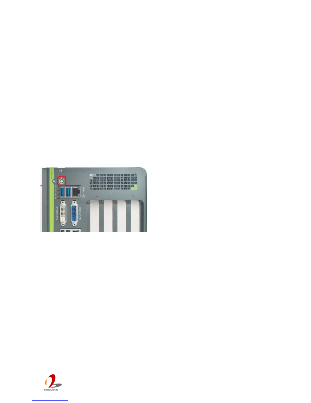
3.7.1 Power on Nuvo-4000 using the power button on the front panel
This is the simplest way to turn on your Nuvo-4000. The power button on the front panel is
a non-latched switch and behaves an ATX-mode on/off control. As DC power is provided,
push the power bu tton and then system is on as well as the P WR LED of power button is on.
Push the button when system is on can turn off the system. If your operating system
supports ATX power mode (i.e. M icros of t Wind ow s or Linux ), push th e power button causes
a pre-defined system behavior, such as shutdown or hibernation.
3.7.2 Power on Nuvo-4000 using Wake-on-LAN function
Wake-on-LAN (WOL) is a mechanism to wake up a computer system from a S3 (standby),
S4 (Hibernate) or S5 (system off with standby power) state via issuing Subnet Directed
Broadcasts (SDB ) or a magic packet. Nuvo-40 00 im plements the W ake-on-LAN function on
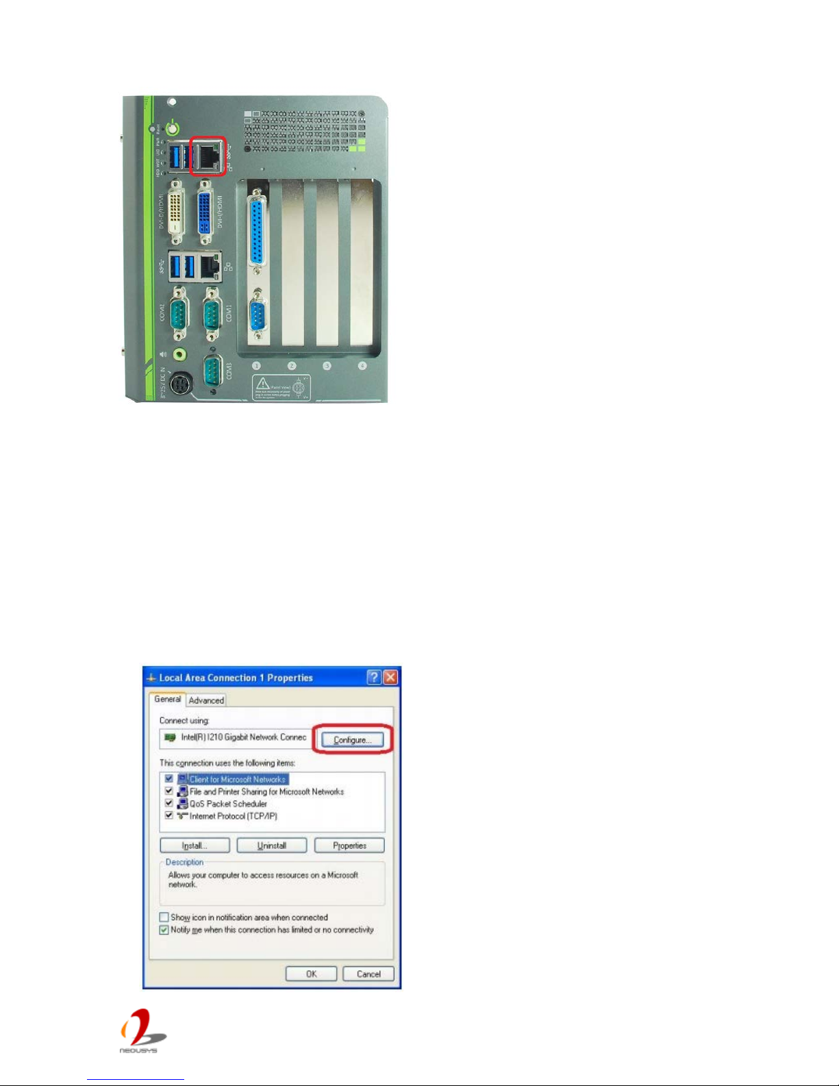
its first GbE port.
Page 47
Nuvo-4 0 00 S er i es User’s Man u al
Copyright © 2014 Neousys Technology Inc. All Right Reserved. Page 47 of 76
To enable WOL funct ion a nd pow er on you Nuvo-4000, p lease f ollow the step s listed below.
For Windows XP
1. When Nuvo-4000 boots up, press F2 to enter BIOS setup utility.
2. Enter the [Power] BIOS setting menu.
3. Configure the [Wake On LAN] BIOS option as [Enabled]. This setting enables the
Wake-on-LAN function for Nuvo-4000. Please refer to section 4.1.8 for the instruc t ion
of configuring this option.
4. In Windows system, identify the Local Area Connection of Intel® I210 Gigabit
Controller and click the Configure button.
Page 48
Nuvo-4 0 00 S er i es User’s Man u al
Copyright © 2014 Neousys Technology Inc. All Right Reserved. Page 48 of 76
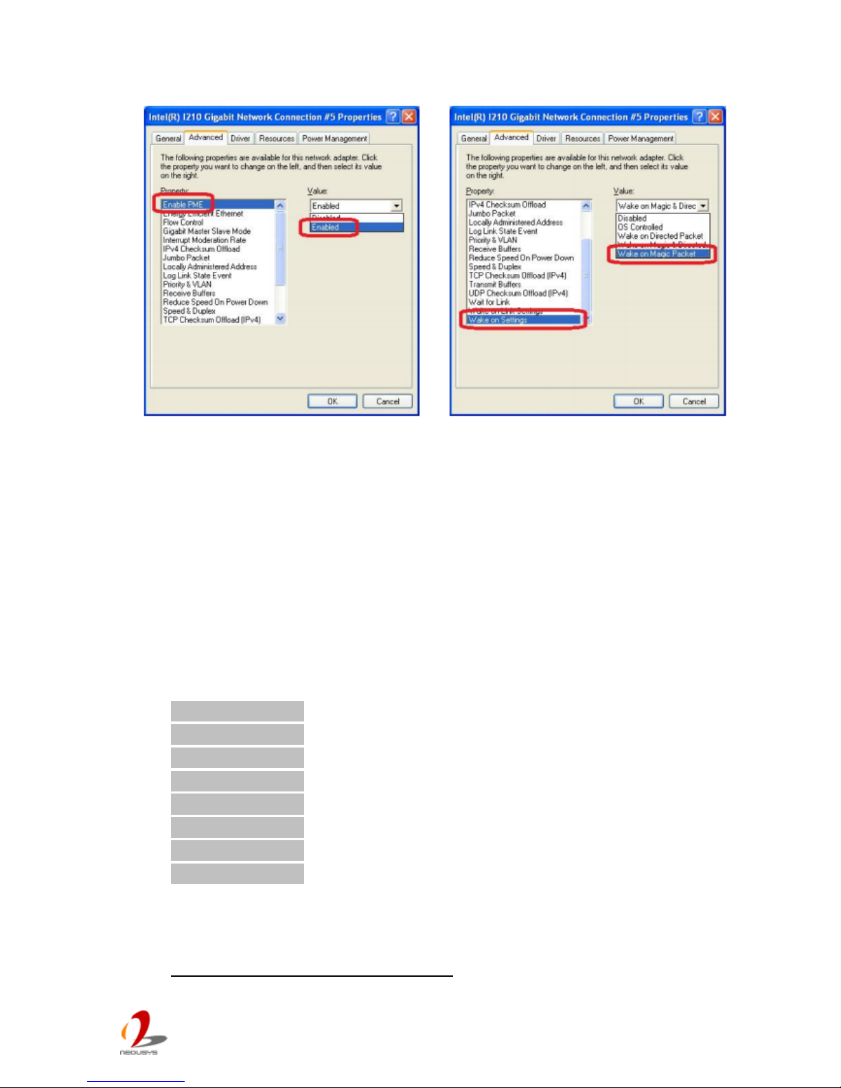
5. Click the Advanced tag, and configure the following two options accordingly.
Enable PME
This option enables Intel® I210 to generate a power management event and
signal the Nuvo-4000 to wake up from S5 state.
Wake on Magic Packet
Nuvo-4000 can wake from S5 state when receiving a magic packet. The magic
packet is a broadcast frame containing anywhere within its payload 6 bytes of all
255 (FF FF FF FF FF FF in hexadecimal), follow ed by sixteen repetit ions of the
target computer's 48-bit MAC address.
For example, NIC’s 48-bit MAC Address is 78h D0h 04h 0Ah 0Bh 0Ch
DESTINATION SOURCE MISC FF FF FF FF FF FF
78 D0 04 0A 0B 0C 78 D0 04 0A 0B 0C
78 D0 04 0A 0B 0C 78 D0 04 0A 0B 0C
78 D0 04 0A 0B 0C 78 D0 04 0A 0B 0C
78 D0 04 0A 0B 0C 78 D0 04 0A 0B 0C
78 D0 04 0A 0B 0C 78 D0 04 0A 0B 0C
78 D0 04 0A 0B 0C 78 D0 04 0A 0B 0C
78 D0 04 0A 0B 0C 78 D0 04 0A 0B 0C
78 D0 04 0A 0B 0C 78 D0 04 0A 0B 0C
MISC CRC
There are some free tools available on Internet that can be used to send a magic
packet. Please refer to the following link to understand more about Magic Packet.
http://en.wikipedia.org/wiki/Wake-on-LAN
Page 49
Nuvo-4 0 00 S er i es User’s Man u al
Copyright © 2014 Neousys Technology Inc. All Right Reserved. Page 49 of 76
For Windows 7
1. When Nuvo-4000 boots up, press F2 to enter BIOS setup utility.
2. Enter the [Power] menu. And configure the [Wake On LAN] option as [Enabled].
This setting enables the Wake -on-LAN function for Nuvo-4000. Please refer to section
4.1.8 for the instruction of configuring this BIOS option.
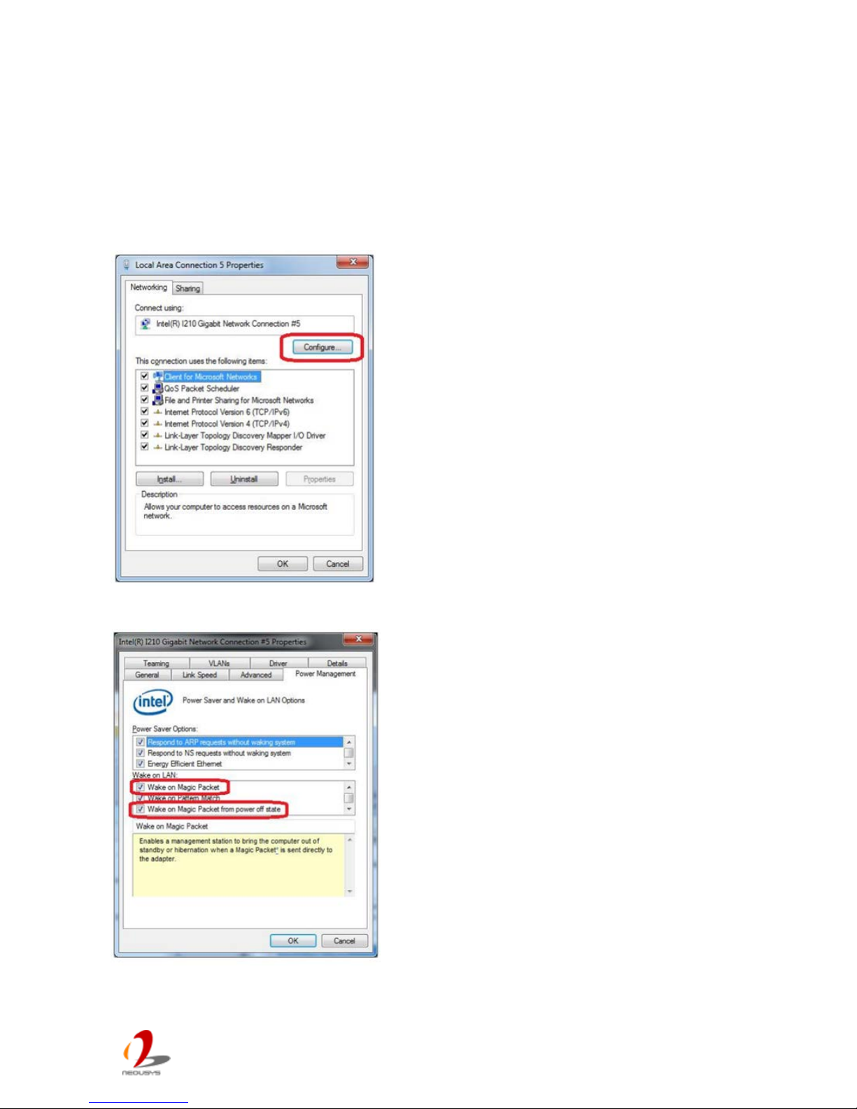
3. In Windows 7 system, identify the Local Area Connection of corresponding Intel® I210
Gigabit Controller and click the Configure button.
4. Click the Power Management tag, and check the following two options accordingly
Page 50
Nuvo-4 0 00 S er i es User’s Man u al
Copyright © 2014 Neousys Technology Inc. All Right Reserved. Page 50 of 76
Chapter 4 BIOS and Driver
4.1 BIOS Settings
Nuvo-4000 is shipped with factory-default BIOS settings cautiously programmed for best
performance and compatibility. In this section, we’ll illustrate some of BIOS settings you
may need to modify. Please always make sure you understand the effect of change before
you proceed with any modification.
4.1.1 COM1 & COM2 Operating Mo de
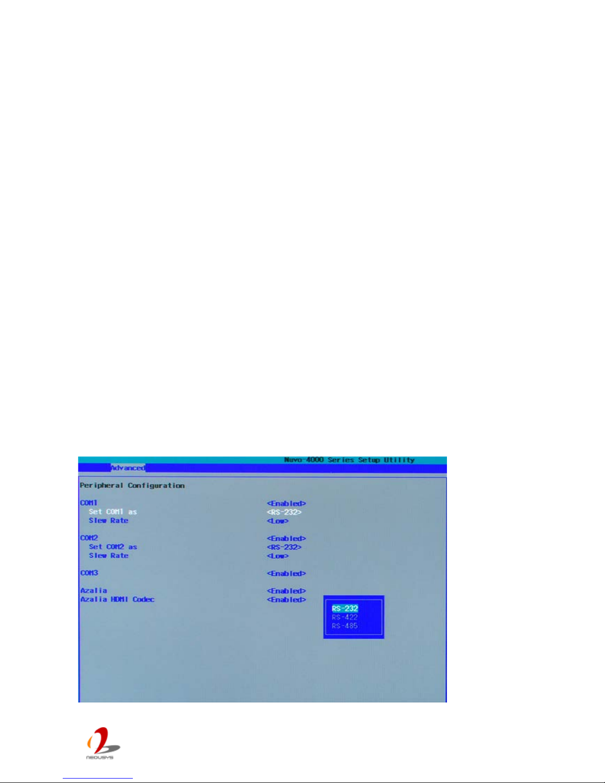
COM1/COM2 of Nuvo-4000 supports RS-232 (full-duplex), RS-422 (full-duplex) and
RS-485 (half-duplex) mode. You can set the COM1/COM2 operating mode vi a BIOS
settings. Another option in BIOS called “Slew Rate” defines how sharp the rising/falling
edge is for the output signal of COM1/COM2. For long-distance RS-422/485 transmission,
you may set the “Slew Rate” option as “High” to improve signal quality.
To set COM1/COM2 operating mode:
1. When Nuvo-4000 boots up, press F2 to enter BIOS setup utility.
2. Go to [Advanced] [Peripheral Configuration].
3. Set the [Set COM1 as] to a proper mode for COM1 of your Nuvo-4000.
4. Set the [Set COM2 as] to a proper mode for COM2 of your Nuvo-4000.
Page 51
Nuvo-4 0 00 S er i es User’s Man u al
Copyright © 2014 Neousys Technology Inc. All Right Reserved. Page 51 of 76
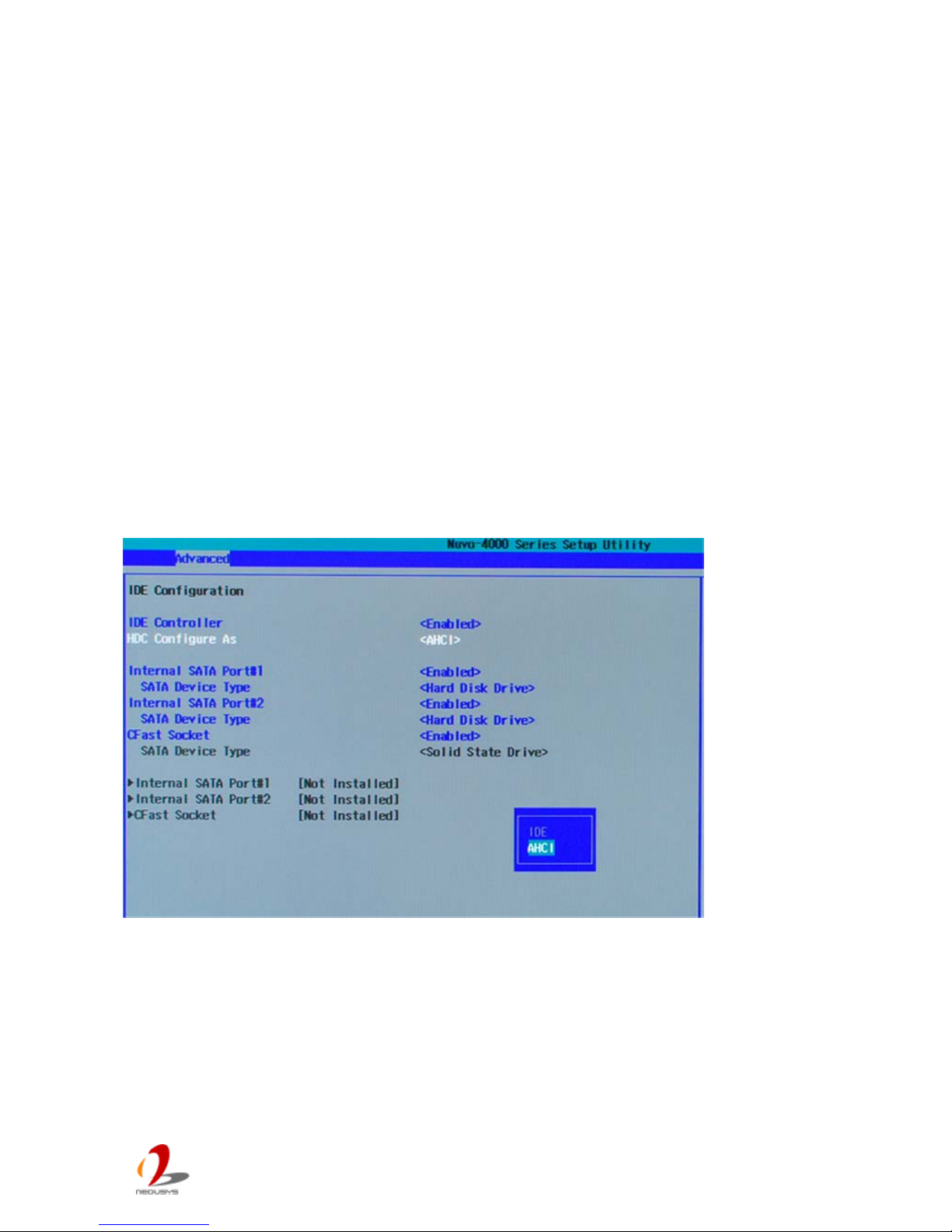
4.1.2 SATA Controller Mode
The SATA controller of Nuvo-4000 supports IDE (non-AHCI) and AHCI mode. IDE mode is
a legacy interf ace and is compatible w ith m ost st orage dev ices. AH CI mode, which exposes
SATA's advanced capabilities such as hot swapping and native command queuing, are
supported in several later version of operating systems.
Our suggestion of how to set SATA controller mode is
- If you’re using Windows XP, Linux kerne l earl ier than 2.6 .19, o r you want to use a CF card,
you should select IDE+SATA (Non-AHCI) mode.
- If you’re using Windows Vista, Windows 7, or Linux kernel from 2.6.19 onward, you can
select AHCI mode for better performance.
To set SATA controller mode:
1. When Nuvo-4000 boots up, press F2 to enter BIOS setup utility.
2. Go to [Advanced] [HDC Configure As].
3. Set the [HDC Configure as] to a proper mode for your Nuvo-4000.
Page 52
Nuvo-4 0 00 S er i es User’s Man u al
Copyright © 2014 Neousys Technology Inc. All Right Reserved. Page 52 of 76
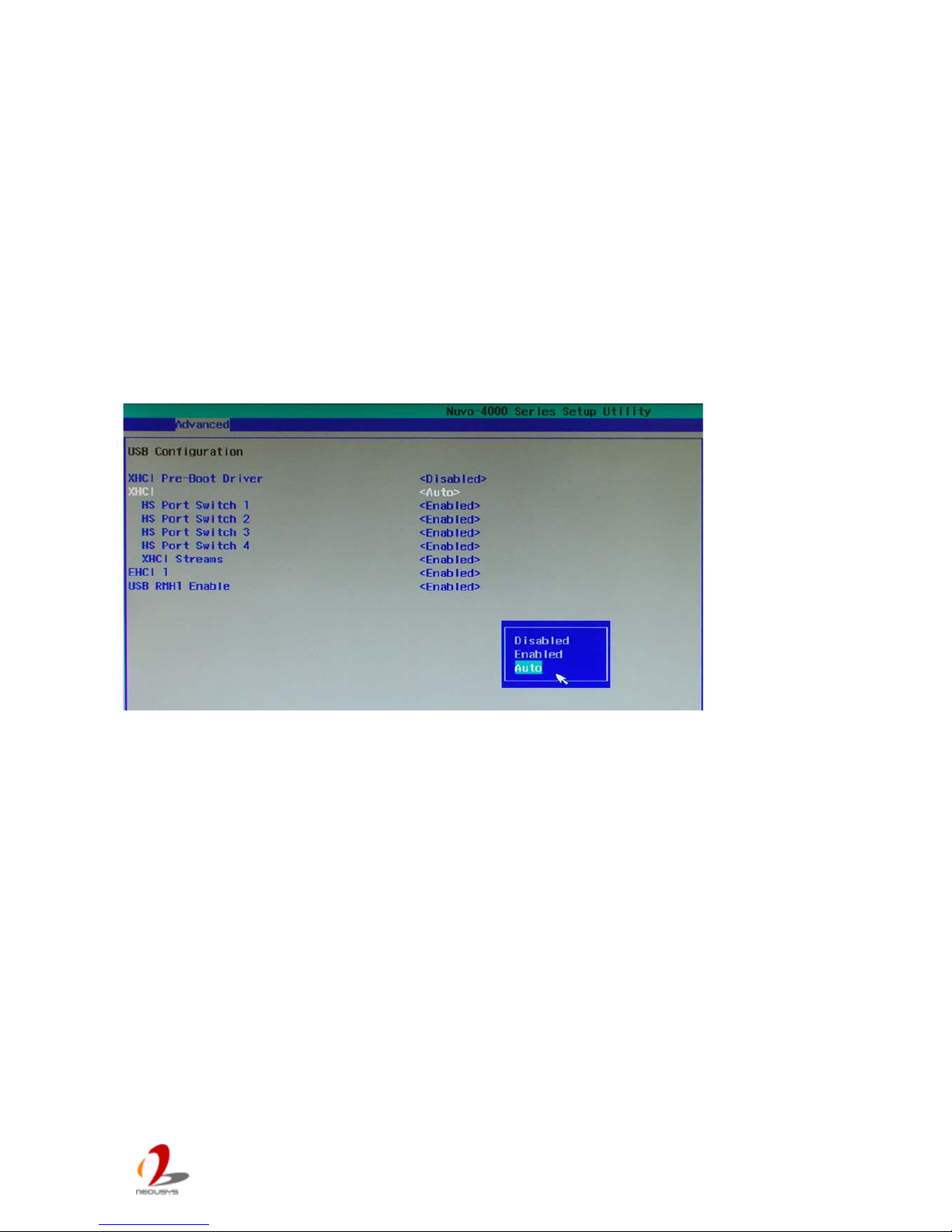
4.1.3 XHCI Support
Nuvo-4000 features XHC/EHCI contro lle r and supports legacy USB devices such as USB
keyboard and mouse. This option determines the enabling/disabling of XHCI contro ller . As
USB 3.0 driver is not available for Windows XP, we suggest you set [XHCI] as “Disabled” to
avoid issue when plugging a USB3 device in XP environment.
To select XHCI controller support:
1. When Nuvo-4000 boots up, press F2 to enter BIOS setup utility.
2. Go to [Advanced] [USB Configuration].
3. Set the [XHCI] to a proper mode for your Nuvo-4000.
Page 53
Nuvo-4 0 00 S er i es User’s Man u al
Copyright © 2014 Neousys Technology Inc. All Right Reserved. Page 53 of 76
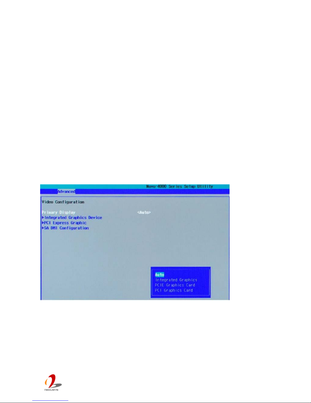
4.1.4 Video Configuration
Nuvo-4000 has an Integrated Intel® HD Graphics 4000 engine in its Core™i5/i7 processor.
For some applications, you may need to install and use a stand-alone graphics card for
display output. When using a PC I or PC I Ex press graph ics car d, you shou ld set th e pr im ary
display device in BIOS in advance.
To set the primary display device:
1. When Nuvo-4000 boots up, press F2 to enter BIOS setup utility.
2. Go to [Advanced] [Video Conf iguration].
3. Set the [Primary Display] to a proper device for your Nuvo-4000.
Select “Integrated Grap hics Device” if using integrate d Intel® HD Graphics 4000
graphics engine
Select “PCIe Graphics Card” if using a PCI Express graphics card
Select “PCI Graphics Card” if using a PCI graphics card
Select “Auto” will specify the following priority for primary display device
PCIe Graphics (if installed) PCI Graphics (if installed) IGD
Page 54
Nuvo-4 0 00 S er i es User’s Man u al
Copyright © 2014 Neousys Technology Inc. All Right Reserved. Page 54 of 76
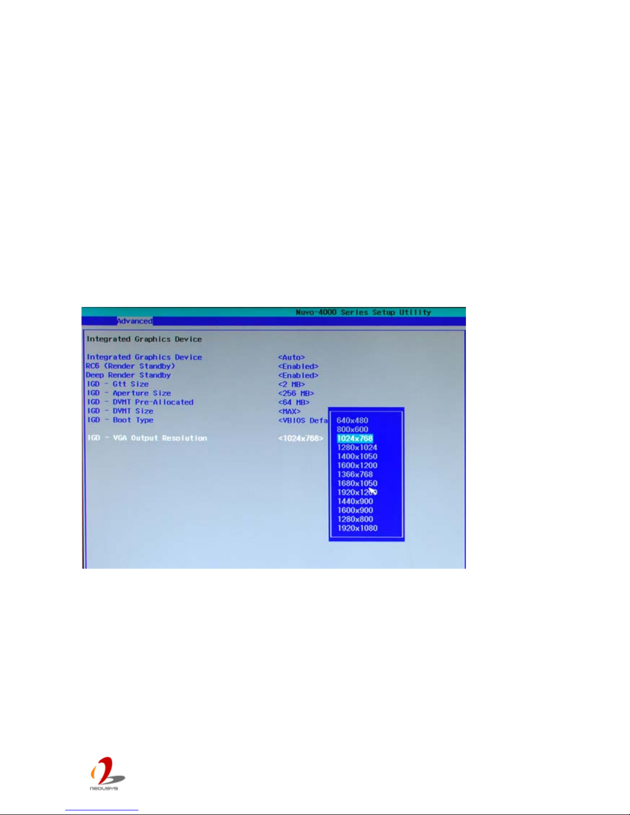
4.1.5 VGA Output Resolution
Nuvo-4000 offers both VGA and DVI display outputs on its DVI-I connector. For supporting
triple independent display outputs, the VGA is implemented via a eDP-VGA converter chip.
To obtain the optimal display performance, you should specify VGA output resolution
according to the best resolution of your display device. Nuvo-4000 supports maximal
1920x1080 resolution for its VGA output.
To set the VGA output resolution:
1. When Nuvo-4000 boots up, press F2 to enter BIOS setup utility.
2. Go to [Advanced] [Video Conf iguration] [Integrated Graphics Device].
3. Set the [VGA Output Resolution] to a proper value acco rd ing to the bes t res olut ion of
your display device.
Page 55
Nuvo-4 0 00 S er i es User’s Man u al
Copyright © 2014 Neousys Technology Inc. All Right Reserved. Page 55 of 76
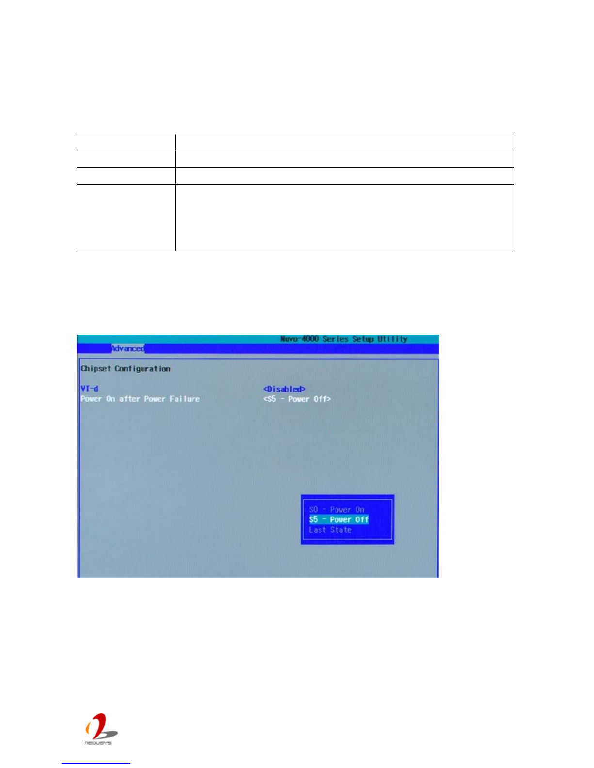
4.1.6 Power On after Power Failure Option
This option defines the behavior of Nuvo-4000 when DC power is supplied.
Value
Description
S0 – Power On
System is powered on when DC power is supplied.
S5 – Power Off System is kept in off state when DC power is supplied.
Last State The on/off state of the system is determined according to the last
state when DC power is disconnected. F
or example, if system is still
on but DC power is unplugged, the system is powered on next time
when DC power is supplied.
To set “Power On after Power Failure” option:
1. When Nuvo-4000 boots up, press F2 to enter BIOS setup utility.
2. Go to [Advanced] [Chipset Configuration]
3. Set the [Power On after Power Failure] to a proper value for your Nuvo-4000.
Page 56
Nuvo-4 0 00 S er i es User’s Man u al
Copyright © 2014 Neousys Technology Inc. All Right Reserved. Page 56 of 76
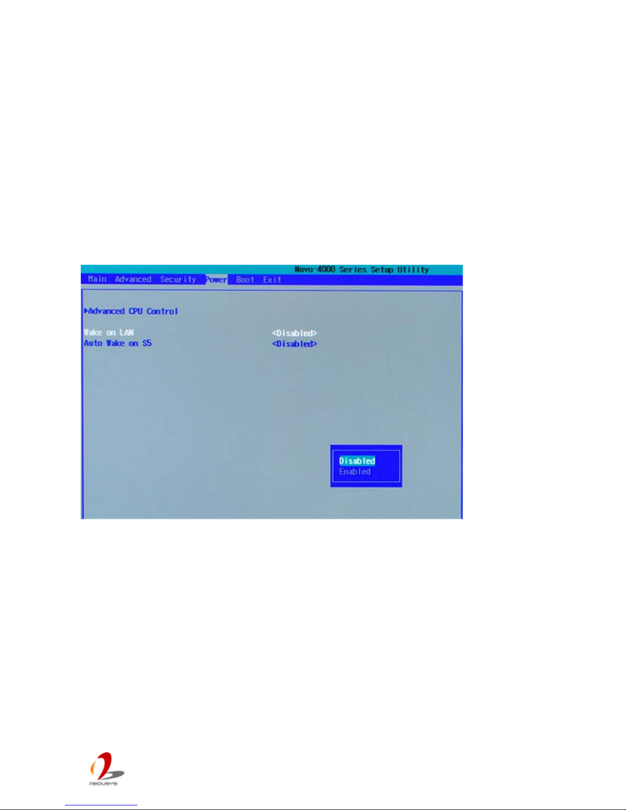
4.1.7 Wake-on-LAN Option
Wake-on-LAN (WOL) is a mechanism which allows you to turn on your Nuvo-4000 by
sending a special Ethernet packet. To utilize Wake-on-LAN function, you have to enable
this option first in BIOS settings. Please refer to section 3.7.2 for instructions of using WOL
function.
To enable/disable “Wake on LAN” option:
1. When Nuvo-4000 boots up, press F2 to enter BIOS setup utility.
2. Go to [Power].
3. Enable/disable the [Wake on LAN] option according to your application.
Page 57
Nuvo-4 0 00 S er i es User’s Man u al
Copyright © 2014 Neousys Technology Inc. All Right Reserved. Page 57 of 76
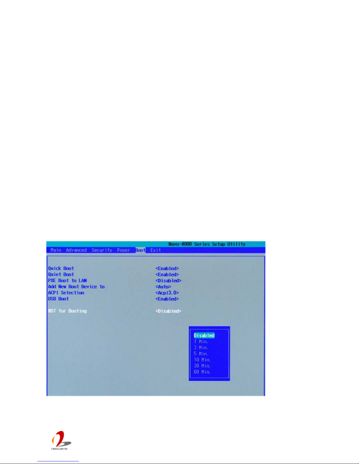
4.1.8 Watchdog Timer for Booting
The BIOS of Nuvo-4000 has a useful feature which allows users to use the watchdog timer
to secure the booting process. You can specify the timeout value for watchdog timer. Once
the watchdog timer expires, the BIOS issues a reset command to initiate another booting
process. You can also set the behavior of how to stop the watchdog timer. There are two
options in BIOS menu, “Automatically after POST” and “Manually after Entering OS”. When
“Automatically after POST” is selected, the BIOS automatically stop the watchdog timer
after POST (Power-On Self Test) OK. When “Manually after Entering OS” is selected, it’s
user’s liability to stop the watchdog timer when entering OS. This guarantees the system
can always boot to OS, otherwise another booting process will be initiated. For information
about programming watchdog timer, please refer to Appendix “A” Using Watchdog Timer &
Isolated DIO.
To set the watchdog timer for boot in BIOS:
1. When Nuvo-4000 boots up, press F2 to enter BIOS setup utility.
2. Go to [Boot].
3. Disable or select timeout value for [WDT for Booting] option.
4. Once you specify a timeout value, the [ WDT Stop Option ] option appears. You can
select “Automatically after POST” or “Manually after Entering OS”.
Page 58
Nuvo-4 0 00 S er i es User’s Man u al
Copyright © 2014 Neousys Technology Inc. All Right Reserved. Page 58 of 76
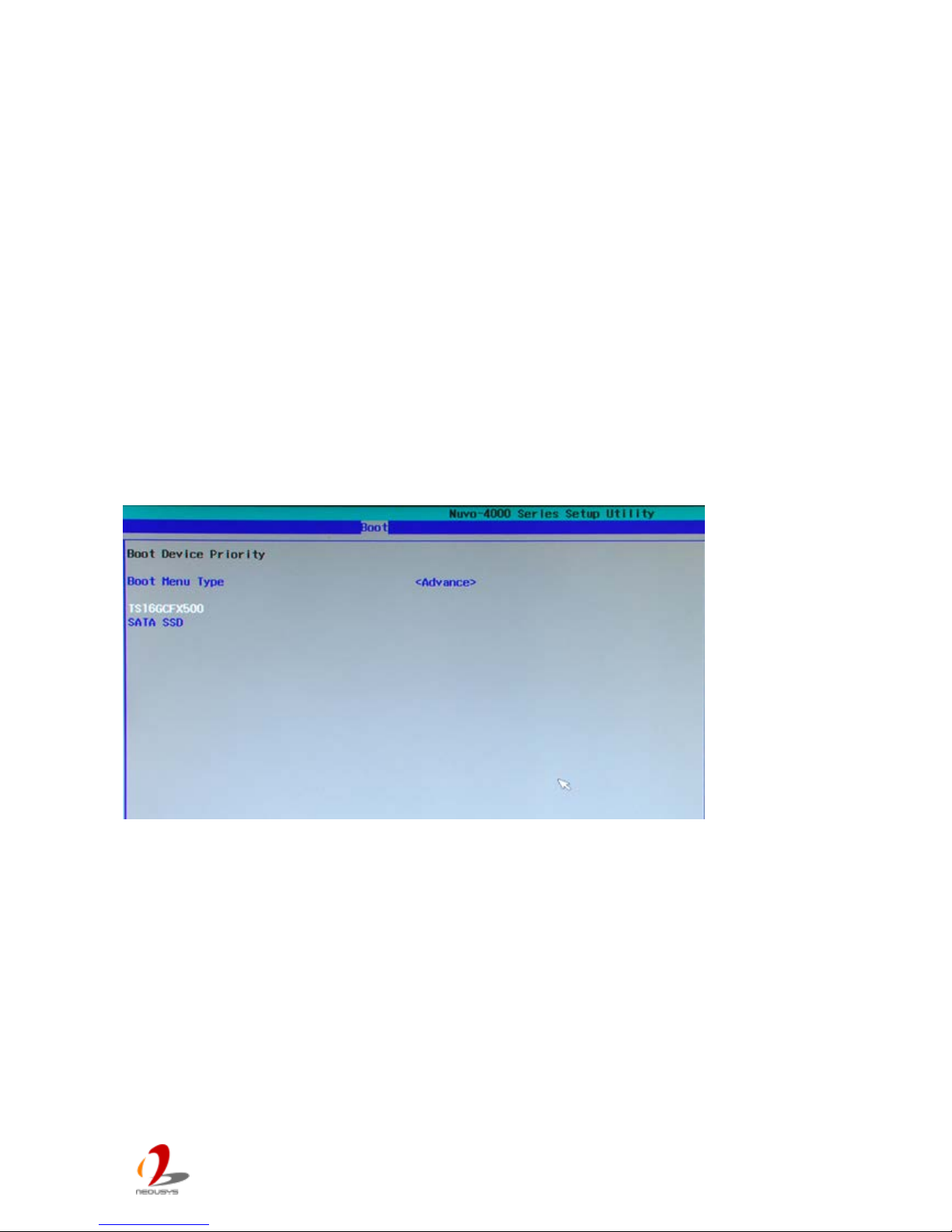
4.1.9 Select a Boot Device
When you have multiple bootable devices connected to your Nuvo-4000 (i.e. HDD, USB
flash disk, USB DVD-drive), you may need to select one of them as the boot device. There
are two ways t o select t he dev ice. You can either, press F 12 when system boot s up to go to
Boot Manager and then select one of the devices, or select the boot device in BIOS
settings.
To select a boot device in BIOS:
1. When Nuvo-4000 boots up, press F2 to enter BIOS setup utility.
2. Go to [Boot] [Boot Device].
3. The [Boot Menu Type] option decides whether to list all bootable devices connected
to your Nuvo-4000 according to device (Advanced mode) or device category (Normal
mode). You can use F5/F6 or +/- to change the boot order of devices or device
categories.
Page 59

Nuvo-4 0 00 S er i es User’s Man u al
Copyright © 2014 Neousys Technology Inc. All Right Reserved. Page 59 of 76
4.2 Operating System Support
Nuvo-4000 supports most operating system developed for Intel® x86 architecture. The
following list contains the operating systems which have been tested in Neousys
Technology Inc.
Microsoft Window XP 32-bit
Microsoft Window 7 32-bit
Microsoft Window 7 64-bit
Ubuntu (version later than 11.04 Desktop 64bit)*
Ubuntu (version later than 10.10 Desktop 32bit)*
Debian (version later than 6.0 64bit)*
Fedora 14 i386 32bit*
CentOS 6.4 32bit
*For Linux system, user may need to manually compile and install the driver for Intel I210 GbE
controller if the driver is not included in the package. You can visit Intel website for further
information.
Neousys will keep this list updated as we continuously test other operating systems with
Nuvo-4000. Please contact us for the latest OS support list.
Page 60
Nuvo-4 0 00 S er i es User’s Man u al
Copyright © 2014 Neousys Technology Inc. All Right Reserved. Page 60 of 76
4.3 Driver Installation
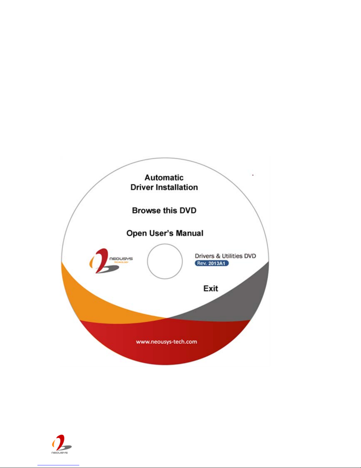
Neousys Technology Inc. provides a very convenient utility in “Drivers & Utilities DVD” to
allow the “One-Click” driver installation. This utility automatically detects your Windows
operating system and installs all necessary drivers to your Nuvo-4000 with just one mouse
click.
4.3.1 Install all drivers using “One-Click” driver installation
1. Insert the “Drivers & Utilities DVD” into a USB DVD-drive attached to your Nuvo-4000.
A setup utility launches and the following dialog appears.
1. Click on the “Automatic Driver Installation”. The setup ut i lity w ill automatically detec t
your Windows operat ing sys tem and install all nec essary d r ivers. Ac cor d ing to dif feren t
versions of Windows, the installation process takes about 6~8 minutes. Once driver
installation is done, the setup utility reboots your Windows and your system works
normally afterward.
Page 61

Nuvo-4 0 00 S er i es User’s Man u al
Copyright © 2014 Neousys Technology Inc. All Right Reserved. Page 61 of 76
4.3.2 Install drivers manually
You can also manually install each driver for Nuvo-4000. Please refer to the following
information about installing drivers for different operating system.
Windows XP SP3
1. The recommended driver installation sequence is
2. Chipset driver (x:\Driver_Pool\Chipset_7_Series\XP\infinst_autol.exe)
3. .NET Framework 3.5 (x:\Driver_Pool\DotNET35\XP\dotnetfx35.exe)
4. Graphics driver (x:\Driver_Pool\Graphics_3rd_i7_Vlv\XP\Setup.exe)
5. Audio driver (x:\Driver_Pool\Audio_ALC262\XP\Setup.exe)
6. LAN driver (x:\Driver_Pool\GbE_I210\XP\I210_XP_Install.exe)
7. ME driver (x:\Driver_Pool\ME_7_Series\ALL\Setup.exe)
Windows XP SP2
1. The recommended driver installation sequence is
2. Chipset driver (x:\Driver_Pool\Chipset_7_Series\XP\infinst_autol.exe)
3. Windows Installer 3.1
(x:\Driver_Pool\DotNET35\XP\WindowsInstaller-KB893803-v2-x86.exe)
4. .NET Framework 3.5 (x:\Driver_Pool\DotNET35\XP\dotnetfx35.exe)
5. Audio patch for HD audio
(x:\Driver_Pool\Audio_ALC262\XP\MSHDQFE\Win2K_XP\us\kb888111xpsp2.exe)
6. Graphics driver (x:\Driver_Pool\Graphics_3rd_i7_Vlv\XP\Setup.exe)
7. Audio driver (x:\Driver_Pool\Audio_ALC262\XP\Setup.exe)
8. LAN driver (x:\Driver_Pool\GbE_I210\XP\I210_XP_Install.exe)
9. ME driver (x:\Driver_Pool\ME_7_Series\ALL\Setup.exe)
Windows 7 32-bit
1. The recommended driver installation sequence is
2. Chipset driver (x:\Driver_Pool\Chipset_7_Series\Win7_8_ALL\SetupChipset.exe)
3. Graphics driver (x:\Driver_Pool\Graphics_3rd_i7_Vlv\Win7_8_32\Setup.exe)
4. Audio driver (x:\Driver_Pool\Audio_ALC262\Win7_8_ALL\Setup.exe)
5. LAN driver
(x:\Driver_Pool\GbE_I210\Win7_8_32\APPS\PROSETDX\Win32\DxSetup.exe)
6. USB 3.0 driver (x:\\Driver_Pool\USB3_7_Series\Win7_ALL\Setup.exe)
7. ME driver (x:\Driver_Pool\ME_7_Series\ALL\Setup.exe)
Page 62

Nuvo-4 0 00 S er i es User’s Man u al
Copyright © 2014 Neousys Technology Inc. All Right Reserved. Page 62 of 76
Windows 7 64-bit
1. The recommended driver installation sequence is
2. Chipset driver (x:\Driver_Pool\Chipset_7_Series\Win7_8_ALL\SetupChipset.exe)
3. Graphics driver (x:\Driver_Pool\Graphics_3rd_i7_Vlv\Win7_8_64\Setup.exe)
4. Audio driver (x:\Driver_Pool\Audio_ALC262\Win7_8_ALL\Setup.exe)
5. LAN driver
(x:\Driver_Pool\GbE_I210\Win7_8_64\APPS\PROSETDX\Winx64\DxSetup.exe)
6. USB 3.0 driver (x:\Driver_Pool\USB3_7_Series\Win7_ALL\Setup.exe)
7. ME driver (x:\Driver_Pool\ME_7_Series\ALL\Setup.exe)
Page 63

Nuvo-4 0 00 S er i es User’s Man u al
Copyright © 2014 Neousys Technology Inc. All Right Reserved. Page 63 of 76
Appendix A Using Watchdog Timer & Isolated DIO
Neousys Nuvo-4000 series provide a watchdog (WDT) timer function to ensure a more
reliable system operation. The WDT is a hardware mechanism to reset the system if the
watchdog timer is expired. Users can start the WDT and keeping resetting the timer to
make sure the system or program is running. Otherwise, the system shall be reset.
In addition to hardware watchdog function, an option of isolated digital I/O is available for
extended range of applications. Nuvo-4000 feature the option of 8x DI channels and 8x DO
channels via an internal 2x13 Pin Header. Neousys also provides a cable/panel kit with
DSub-25 connector for front-panel access. The optional digital I/O supports standard
polling mode I/O access so users’ program can read or write DIO channel(s) using this
function library. It also features an enhanced mode called “Change-of-State Interrupt”. By
detecting any change on digital input channel(s), an interrupt is generated according to a
user-defined interrupt mask and level/edge setting, so user’s program can react to the
change.
In this document, we’ll illustrate how to use the function library provided by Neousys to
program the WDT and DIO functions. Currently, WDT & DIO driver library supports the
following operating systems:
Windows XP
Windows Vista (32-bit)
Windows 7 (32-bit & 64-bit)
For other OS support, please contact Neousys Technology for further information.
Page 64
Nuvo-4 0 00 S er i es User’s Man u al
Copyright © 2014 Neousys Technology Inc. All Right Reserved. Page 64 of 76
A.1 Install WDT and DIO Library
The WDT_DIO function library is delivered in the form of a setup package named
WDT_DIO_Setup.exe. In prior to program WDT and DIO on Nuvo, Nuvis and POC series,
you should execute the setup program and install the WDT and DIO library.
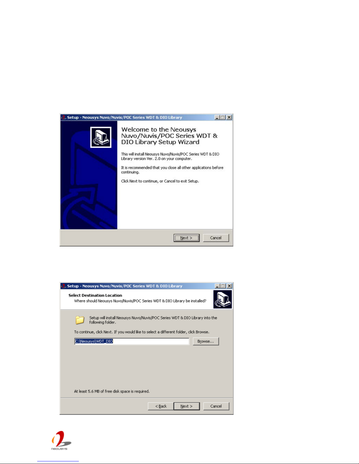
1. Execute WDT_DIO_Setup.exe. The following dialog appears.
2. Click “Next >” a nd sp ecif y the d irect ory o f insta lling re lated f i les. The defau lt d irectory is
C:\Neousys\WDT_DIO.
Page 65
Nuvo-4 0 00 S er i es User’s Man u al
Copyright © 2014 Neousys Technology Inc. All Right Reserved. Page 65 of 76
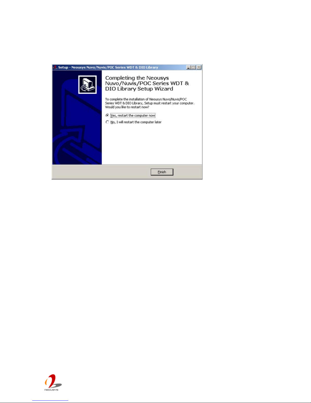
2. Once the installation is finished, a dialog appears to prompt you to reboot the system.
The WDT & DIO library will take effect after system rebooting.
4. When you programming your WDT or DIO program, the related files are located in
Header file: \Include
Lib file: \Lib
Function Reference: \Manual
Sample Code: \Sample
Page 66

Nuvo-4 0 00 S er i es User’s Man u al
Copyright © 2014 Neousys Technology Inc. All Right Reserved. Page 66 of 76
A.2 Using WDT Function
WDT Function Reference
InitWDT
Description
Initialize the WDT function. You should always invoke InitWDT() before set or start
watch-dog timer.
Parameter
None
Return Value
Always returns TRUE
Usage
BOOL bRet = InitWDT()
SetWDT
Description
Set timeout value and unit for watch-dog tim er. When Init WDT() is invoked, a default
timeout value of 255 seconds is assigned.
Parameter
tick
WORD value (1 ~ 65535) to indicate timeout ticks.
unit
BYTE value (0 or 1) to indicate unit of timeout ticks.
0 : unit is minute
1: unit is second
Return Value
If value of unit is correct (0 or 1), this function returns TRUE, otherwise FALSE.
Usage
WORD tick=255;
BYTE unit=1; //unit is second.
BOOL bRet = SetWDT(tick, unit); //timeout value is 255 seconds
Page 67

Nuvo-4 0 00 S er i es User’s Man u al
Copyright © 2014 Neousys Technology Inc. All Right Reserved. Page 67 of 76
StartWDT
Description
Start countdown of WDT. When WDT is started, the WDT LED indicator starts to blink
in a frequency of 1Hz. If no ResetWDT() or StopWDT is invoked before WDT is
counted to 0, the WDT expires and system resets.
Parameter
None
Return Value
If the timeout value is given in correct format, this function returns TRUE, otherwise
FALSE.
Usage
BOOL bRet = StartWDT()
ResetWDT
Description
Reset the timeout value to the value given by SetWDT(). If no ResetWDT() or
StopWDT is invoked before WDT is counted to 0, the WDT expires and system resets.
Parameter
None
Return Value
Always returns TRUE;
Usage
BOOL bRet = ResetWDT()
StopWDT
Description
Stop the countdown of WDT. When WDT is stopped, the WDT LED indicator stops
blinking.
Parameter
None
Return Value
Always returns TRUE;
Usage
BOOL bRet = StopWDT()
Page 68
Nuvo-4 0 00 S er i es User’s Man u al
Copyright © 2014 Neousys Technology Inc. All Right Reserved. Page 68 of 76
A.3 Using DIO Function
Wiring for DIO
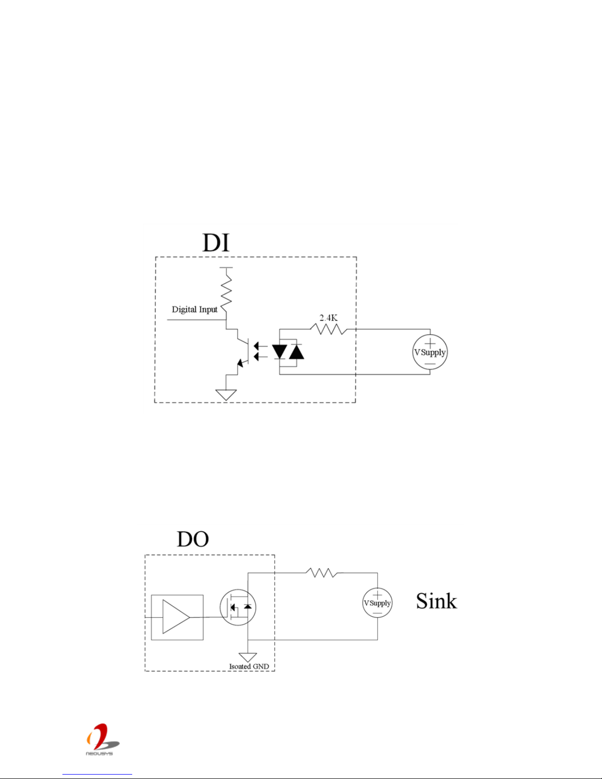
The digital input function of Nuvo-4000 is im plem ented using a photo-coupler with a
internally series-connected 4.7k ohm resistor. You need to provide a voltage to specify the
logic high/low s tate. The input vo lta ge for log ic high is 5~24V , and th e input vo ltage f o r logic
low is 0~1.5V
The digital output function of Nuvo-4000 is implemented using Power MOSFET + Analog
Device iCoupler® component. The DO channels are configured as NO (normall y-open)
configuration. When you turn on Nuvo-4000, all DO channels have a deterministic state of
logic 0 (circuit disconnected from GND return). When logic 1 is specified, MOSFET is
activated and GND return path is established. You should configure a sinking current
connection for DO of Nuvo-4000. The following diagrams are the suggested wiring for DO:
Page 69
Nuvo-4 0 00 S er i es User’s Man u al
Copyright © 2014 Neousys Technology Inc. All Right Reserved. Page 69 of 76
DIO Function Reference
InitDIO
Description
Initialize the DIO function. You should always invoke InitDIO() before write/read any
DIO port/channel.
Parameter
None
Return Value
Returns TRUE if initialization successes, FALSE if initialization failed.
Usage
BOOL bRet = InitWDT()
DIReadLine
Description
Read a single channel of isolated digital input.
Parameter
ch
BYTE value specifies the DI channel to be read.
For Nuvo-4000, ch should be a value of 0 ~ 7.
Model Series DO channel Value
Nuvo-1000 8 000b ~111b
Nuvo-1300af 8 000b ~111b
Nuvo-2000+ 8 000b ~111b
Nuvo-3000 8 000b ~111b
Nuvo-4000 8 000b ~111b
POC-100 4 00b~11b
POC-200 4 00b~11b
Return Value
The status (TRUE or FALSE) of the specified DI channel.
Usage
BYTE ch=3; //DI channel #3
BOOL DIChValue = DIReadLine(ch); //read DI channel #3
Page 70

Nuvo-4 0 00 S er i es User’s Man u al
Copyright © 2014 Neousys Technology Inc. All Right Reserved. Page 70 of 76
DIReadPort
Description
Read the entire isolated digital input port (8 channels).
Parameter
None
Return Value
A WORD value indicates the status of DI port (8 DI channels).
Usage
WORD DIPortValue = DIReadPort ();
DOWriteLine
Description
Write a single channel of isolated digital output.
Parameter
ch
BYTE value specifies the DO channel to be written.
For Nuvo-4000, ch should be a value of 0 ~ 7.
Model Series DO channel Value
Nuvo-1000 8 000b ~111b
Nuvo-1300af 8 000b ~111b
Nuvo-2000+ 8 000b ~111b
Nuvo-3000 8 000b ~111b
Nuvo-4000 8 000b ~111b
POC-100 4 00b~11b
POC-200 4 00b~11b
value
BOOL value (TRUE or FALSE) specifies the status of DO channel.
Return Value
None
Usage
BYTE ch=3; //DI channel #3
BOOL DOChValue=TRUE;
DOWriteLine(ch, DOChValue); //write DO channel #3 as TRUE
Page 71
Nuvo-4 0 00 S er i es User’s Man u al
Copyright © 2014 Neousys Technology Inc. All Right Reserved. Page 71 of 76
DOWritePort
Description
Write the entire isolated digital output port (8 channels).
Parameter
value
WORD value specifies the status of the DO port.
For Nuvo-4000, value should be a value of 0~255.
Model Series DO Port Number Value
Nuvo-1000 8 00000000b ~11111111b
Nuvo-1300af 8 00000000b ~ 11111111b
Nuvo-2000+ 8 00000000b ~11111111b
Nuvo-3000 8 00000000b ~11111111b
Nuvo-4000 8 00000000b ~11111111b
POC-100 4 0000b~1111b
POC-200 4 0000b~1111b
Return Value
None
Usage
WORD DOPortValue=0x3F; //00111111b
DOWritePort(DOPortValue); //write DO port as 00111111b
Page 72

Nuvo-4 0 00 S er i es User’s Man u al
Copyright © 2014 Neousys Technology Inc. All Right Reserved. Page 72 of 76
A.4 Usi ng CO S Function
Change-of-State DIO Function Reference
SetupDICOS
Syntax
BOOL SetupDICOS(COS_INT_SETUP *lpSetup, DWORD cbSetup);
Description
Setup Digital-Input(DI) Change-of-State(COS) interrupt parameters.
Parameter
lpSetup [in]
A pointer to a COS_INT_SETUP structure that contains the COS configuration
information for the DI device.
This data structure contains the following variables:
portMask
WORD value specifies the interrupt mask for corresponding channel(s).
edgeMode
WORD value spec ifies that interrupt is ge nera t ed when level change (set to 0 )
or on rising/falling edge (set to 1) for the corresponding channel(s).
edgeType
WORD value specifies that interrupt is generated on rising edge (set to 0) or
falling (set to 1) edge for corresponding channel(s). This value is neglected if
edgeMode is set to 0 for the corresponding channel(s).
cbSetup [in]
The length of the structure, in bytes. The caller must set this member to
sizeof(COS_INT_SETUP).
Return Value
Returns TRUE if setup successes, FALSE if setup failed.
Usage
COS_INT_SETUP setup;
memset(&setup, 0, sizeof(setup));
setup.portMask = 0xff; // enable ch.0~7
setup.edgeMode = 0; // level
setup.edgeType = 0x00; // Lo/Hi
BOOL bRet = SetupDICOS(&setup, sizeof(setup));
Page 73

Nuvo-4 0 00 S er i es User’s Man u al
Copyright © 2014 Neousys Technology Inc. All Right Reserved. Page 73 of 76
RegisterCallbackDICOS
Syntax
BOOL RegisterCallbackDICOS(COS_INT_CALLBACK callback);
Description
Registers a callback function, which is called when the DICOS interrupt occurred.
Parameter
callback [in]
Specifies the callback function. The prototype for this function is descripted as
follow.
void __stdcall callback_func(COS_INT_CALLBACK_ARG* arg);
Return Value
Returns TRUE if setup successes, FALSE if setup failed.
Usage
void __stdcall callback_func(COS_INT_CALLBACK_ARG* arg)
{
printf("data=0x%02x, flag=0x%02x, seq=%02d\n",
arg->portData, arg->intrFlag, arg->intrSeq);
}
BOOL bRet = Regi s terCallbackDICOS(callback_func);
StartDICOS
Syntax
BOOL StartDICOS(void);
Description
Start DI Change-of-State interrupt
Parameter
None
Return Value
Returns TRUE if start procedure successes, FALSE if start procedure failed.
Usage
BOOL bRet = StartDICOS();
Page 74

Nuvo-4 0 00 S er i es User’s Man u al
Copyright © 2014 Neousys Technology Inc. All Right Reserved. Page 74 of 76
StopDICOS
Syntax
BOOL StopDICOS(void);
Description
Stop DI Change-of-Stat e interrupt
Parameter
None
Return Value
Returns TRUE if stop procedure successes, FALSE if stop procedure failed.
Usage
BOOL bRet = StopDICOS();
Change-of-State DI Example
#include <stdio.h>
#include <stdlib.h>
#include <windows.h>
#include "WDT_DIO.h"
//Step 0, define a Change-of-State Interrupt callback function
void __stdcall callback_function(COS_INT_CALLBACK_ARG* arg)
{
printf("data=0x%02x, flag=0x%02x, seq=%02d\n",
arg->portData, arg->intrFlag, arg->intrSeq);
}
int main(int argc, char* argv[])
{
//Step 1, initialize DIO library by invoking InitDIO()
if ( ! InitDIO() )
{
printf("InitDIO --> FAILED\n");
return -1;
}
printf("InitDIO --> PASSED\n");
//Step 2, setup Change-of-State Interrupt mask and level/edge mode
Page 75

Nuvo-4 0 00 S er i es User’s Man u al
Copyright © 2014 Neousys Technology Inc. All Right Reserved. Page 75 of 76
COS_INT_SETUP setup;
memset(&setup, 0, sizeof(setup));
setup.portMask = 0x0f; // 00001111b, enable ch.0~3
setup.edgeMode = 0x00; // generate interrupt on level change
setup.edgeType = 0x00; // rising/falling edge, only effective when edgeMode = 1
if ( ! SetupDICOS(&setup, sizeof(setup)) )
{
printf("SetupDICOS --> FAILED\n");
return -2;
}
printf("SetupDICOS --> PASSED\n");
//Step 3, register the callback function
if ( ! RegisterCallbackDICOS(callback_function) )
{
printf("RegisterCallbackDICOS --> FAILED\n");
return -3;
}
printf("RegisterCallbackDICOS --> PASSED\n");
//Step 4, start the DI Change-of-State Inter rupt
if ( ! StartDICOS() )
{
printf("StartDICOS --> FAILED\n");
return -4;
}
printf("StartDICOS --> PASSED\n");
printf("\npress any key to stop...\n");
system("pause >nul");
//Step 5, stop the DI Change-of-State Interrupt operation
if ( ! StopDICOS() )
{
printf("StopDICOS --> FAILED\n");
return -5;
}
Page 76

Nuvo-4 0 00 S er i es User’s Man u al
Copyright © 2014 Neousys Technology Inc. All Right Reserved. Page 76 of 76
printf("StopDICOS --> PASSED\n");
printf("\npress any key to exit...\n");
system("pause >nul");
return 0;
}
 Loading...