

Page 1
FSW-41HP
Unmanaged Industrial 4-port 10/100Base-TX + 1-port 100Base-FX SFP Ethernet Switch with PoE+
This quick start guide d es cr ibes how to install and us e the I ndus tr ial Po E Unmanaged Ethernet S witc h. This is the
Switch of choice for harsh environments.
Overview
The FSW-41HP product is an industrial unmanaged switch which provides 4 port 10/100Base-TX +
1x100Base-FX SFP port. The 10/100Base-TX ports supports PoE (Power Sourcing Equipment) and
compliant with IEEE 802.3at.
Compliant with IEEE802.3 10Base-T, IEEE802.3u 100Base-Tx, IEEE802.3x, and IEEE802.3at. The
product will provide PoE power to any IEEE802.3at compliant network device. With its reliable design and
ease of use, the product is a great choice for integrating networks consisting of network devices such as
IP cameras and wireless access points between remote locations.
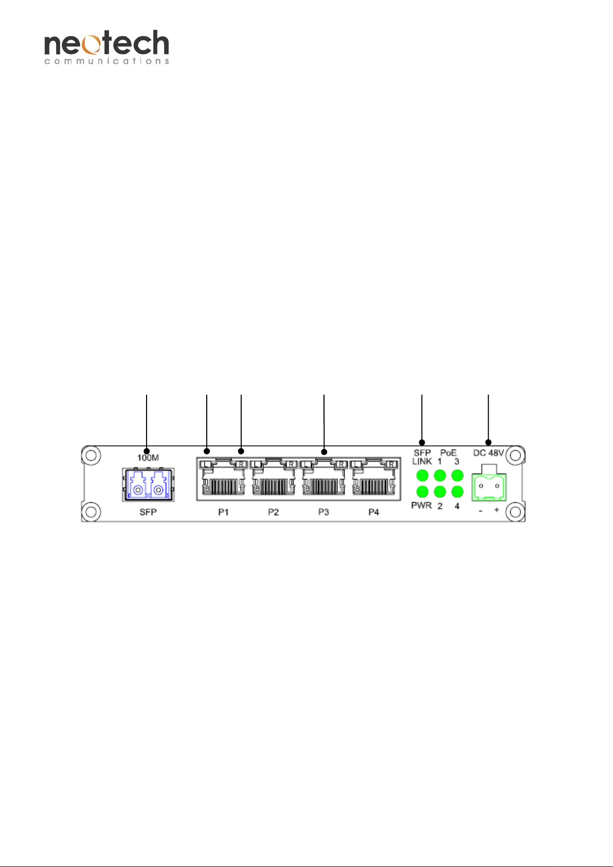
Physical Description
Front Panel
Optical SPD LINK/ACT Ethernet Indicator Power Input
General
To ensure trouble free transportation and storage, all Neotech products must be thoroughly inspected,
tested and well packed before delivery. Check the product upon receipt for any visible damage which
may have been caused during shipping.
The product can be mounted on walls or rest on table tops and operates with an external 48V power
adapter.
1 V1
Page 2
FSW-41HP
Unmanaged Industrial 4-port 10/100Base-TX + 1-port 100Base-FX SFP Ethernet Switch with PoE+
Installation
1. Connect one end of the Ethernet cables to their corresponding ports on the product. Connect the
other end to the network equipment such as IP cameras, Switches or PCs. Insert the SFP and
connect the optical fiber cables to its connectors.
2. Connect the product with the power adapter and switch on the product, the PWR indicator should
then be ON. If it is not, please check whether the power cable is connected properly and the power
supply functions normally.
3. After all cables are connected, corresponding indicators will be on. Please refer to the Operational
Instructions for detail descriptions.
Cable Connections
Signal Type Cable Type Connector
Ethernet Cat. 5 or above RJ45
Optical SM/MM Optical fiber cable (depends on SFP) LC
Power supply Power cable 2-pin T erminal Block
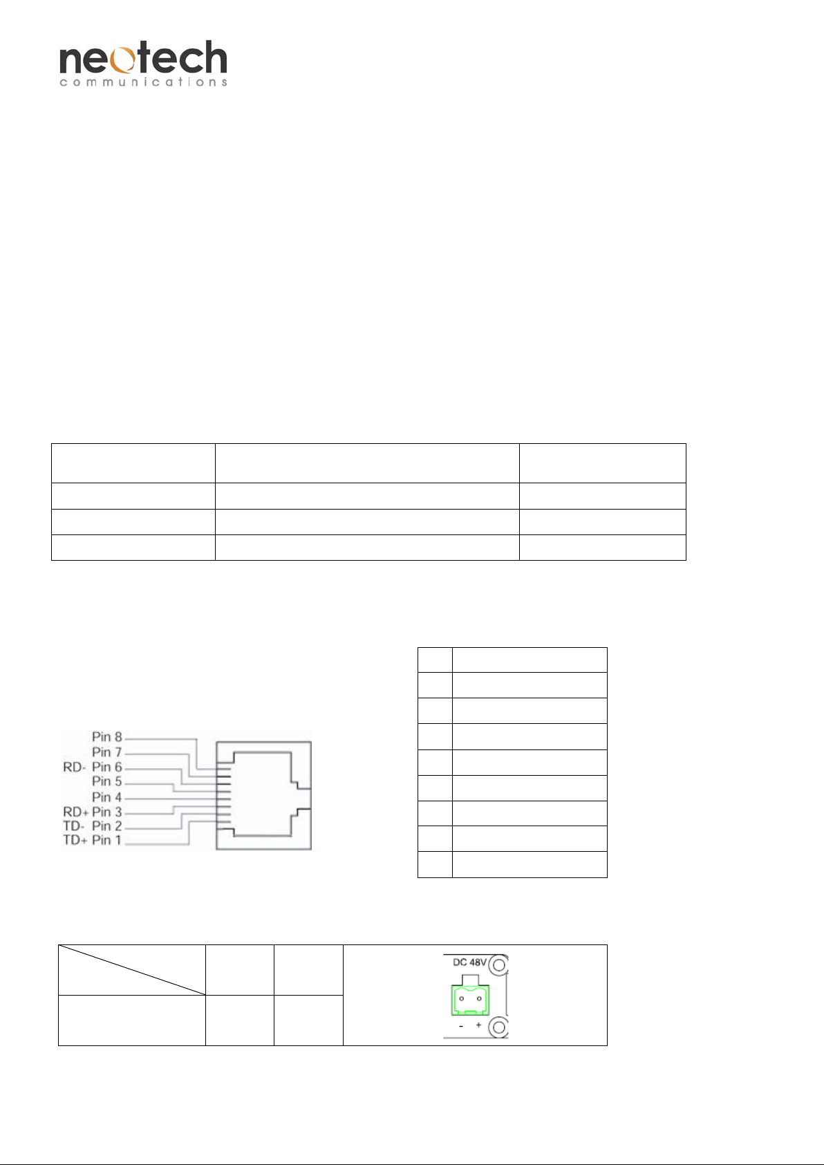
Interface Ethernet Port:
Pin Assignment
RJ45 Pin Assignment:
1 Output Transmit Data +
2 Output Transmit Data -
3 Input Receive Data +
4 Positive (VCC+)
5 Positive (VCC+)
6 Input Receive Data 7 Negative (VCC-)
8 Negative (VCC-)
Power Connector:
Pin
Description
Power Input
- +
+48V
GND
(DC)
2 V1
Page 3

FSW-41HP
Unmanaged Industrial 4-port 10/100Base-TX + 1-port 100Base-FX SFP Ethernet Switch with PoE+
Operational Instructions
Indicators
Indicator Color Status Description
RJ45
Port
(P1-P4)
Ports
PWR Green
SFP LINK Green
PoE (1-4) Green
LINK/ACT Green
Orang
SPD
e
P1-P4 Ethernet ports
ON Powered on
ON Fiber link up
Blinking The fiber link is receiving or transmitting data
OFF Fiber is not connected or fiber link down
ON PoE is activated.
Blinking A Power Device (PD) is being detected.
OFF No de vice is connected or the connecte d device is not
a PD.
ON A network device is connected
Blinking The connected device is transmitting or receiving data.
OFF No network device is connected
ON 100Base-TX
OFF 10Base-TX mode
SFP Fiber port
Power Input DC 48V input
Functional Description
• Supports IEEE802.3at Power over Ethernet (POE+)
• 1 SFP (mini-GBIC) supports 10/100Base-FX speed
• Support Auto-Negotiation and Auto-MDI/MDI-X
• Support Store-and-Forward T ransmission
• Support Wall-mount installation
• -10℃ to 60℃ (14℉ to 140℉) operating temperature
Assembly, Startup, and Dismantling
Wall Mounting Installation
• Assembly: Mount the standalone unit onto a fixture, e.g. a plank, (either on the wall or on a flat
surface) with at least 2 screws piercing through the holes on the mounting frame to secure it in
position.
• Startup: Connect the supply voltage to start up the Switch via the terminal block.
• Dismantling: Locate and remove the securing screws. Usually, but not limited to, at least 2 screws.
Manual Earth Green manual is availabl e on our w ebsi te. www.neotechcomm.com.tw
3 V1
 Loading...