

Page 1
X
(
X
)
X
r
X
r
X
FSW-21F-CM Series
Industrial 2-port 10/100Base-TX to 100Base-FX Switch
This quick start guide describes how to install and use the Industrial Switch. This is the Switch introduced here provides two port 10/100Base-TX
to 100Base-FX.
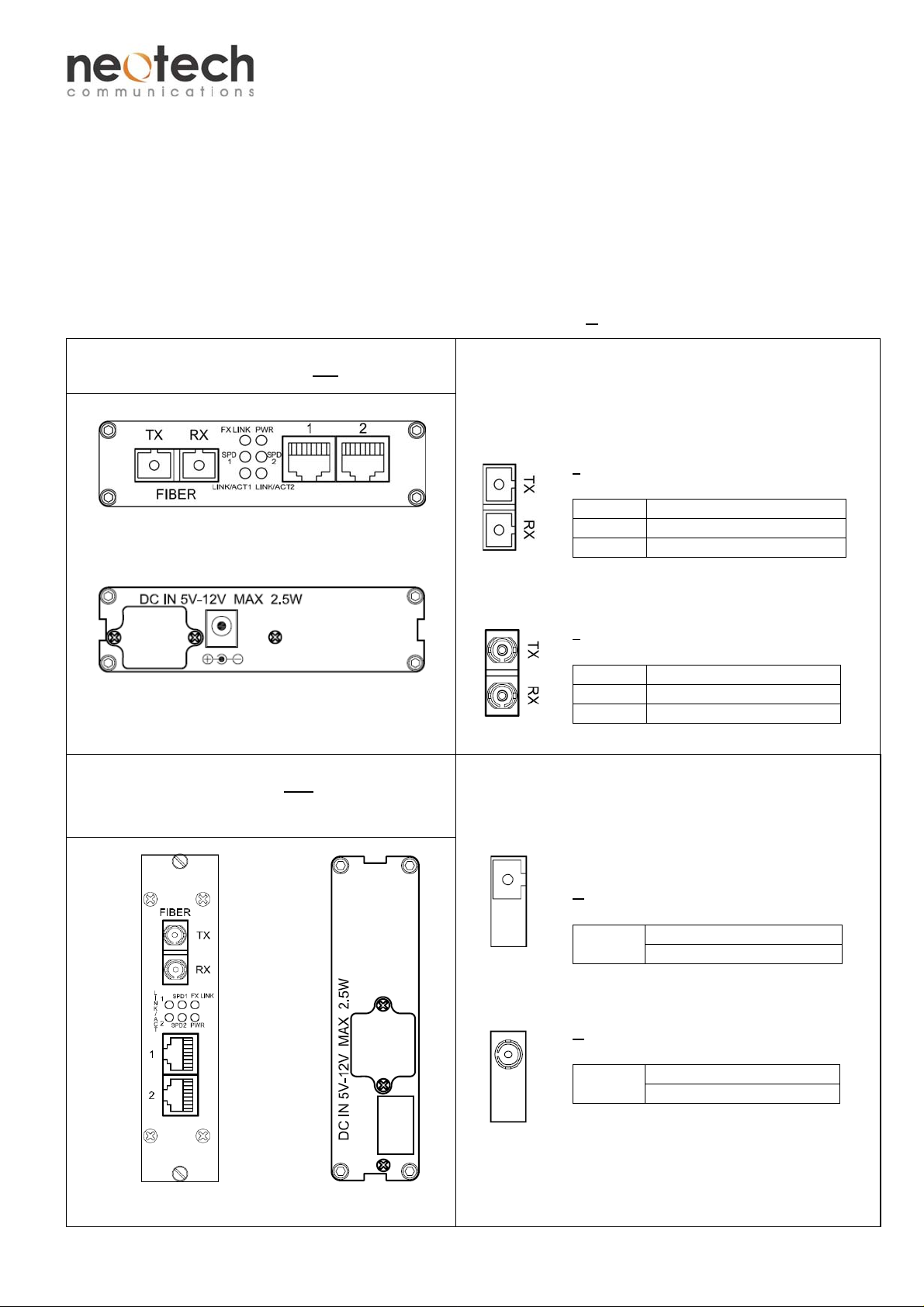
Physical Description
The 100Base-FX connections and Power inputs
Front and rear panel of FSW-21F-YY-
Standalone Unit (FSW-21F-SA-X)
Front panel
Rear Panel
Power Input Assignment-DC Jack
The fiber port(s) for 100Base-FX connections
FSW-21F-YY-
The 100Base-FX Connections
The TX (transmit) port of device I is connected to the RX (receive) port of
device II, and
the RX (receive) port of device I to the TX (transmit) port of device II.
value:
A for Multimode fiber
B for Singlemode fiber
FIBER Connector
TX SC Optical Connector
RX SC Optical Connecto
value:
G for Multimode fiber
H for Singlemode fiber
FIBER Connector
TX ST Optical Connector
RX ST Optical Connecto
Card Module (FSW-21F-CM-X)
Power Input by build-in NC-PSU/5V in NC-R12
Front panel
Rear Panel
The WDM 100Base-FX Connections
Only one single-mode optical fiber is required to transmit and receive data.
X value:
C and D for Multimode fiber
H and F for Singlemode fiber
FIBER
value:
I and J for Multimode fiber
K and L for Singlemode fiber
FIBER
Connector
SC Optical Connector
Connector
ST Optical Connector
V3 1
Page 2
FSW-21F-CM Series
Industrial 2-port 10/100Base-TX to 100Base-FX Switch
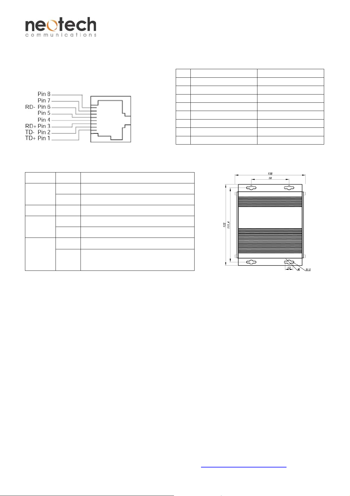
The 10/100Base-TX
The 10/100Base-TX Connections
The following lists the pinouts of 10/100Base-TX ports.
Pin Regular Ports Uplink port
1 Output Transmit Data + Input Receive Data +
2 Output Transmit Data - Input Receive Data 3 Input Receive Data + Output Transmit Data +
4 NC NC
5 NC NC
6 Input Receive Data - Output Transmit Data 7 NC NC
8 NC NC
The Port Status LEDs, dimension drawing for the Standalone unit
LED State Indication
PWR
FX LINK
SPD1, 2
LINK/ACT
Green Power on.
Off Power off.
Green 100Base-FX
Green 100Base-TX
Amber 10Base-TX
Steady A valid network connection established
1, 2
Flashing Transmitting or receiving data. ACT Stands for
Activity.
Functional Description
Converts 10/100Base-TX to 100Base-FX
Full/Half duplex, Auto-Negotiation
Singlemode or Multimode fiber operation
Single or Dual-core fiber with SC or ST connectors
Store and forward switching mechanism
MDI/MDI-X Auto-Crossover supported
Plug-and-Play / Hot-swappable
-20 °C to 60 °C (-4 °F to 140 °F) operating temperature
Wall-mount or operate in NC-R12 rack mount chassis
Assembly, Startup, and Dismantling
Standalone units Installation
Assembly: Mount the standalone unit onto a fixture, e.g. a plank, (either on the wall or on a flat surface) with at least 2
screws piercing through the holes on the mounting frame to secure it in position.
Startup: Connect the supply voltage to start up the Media Converter via the terminal block.
Dismantling: Locate and remove the securing screws. Usually, but not limited to, at least 2 screws.
Card Module Installation
Assembly: The Card Module can be used as slide-in module to the NC-R12 (12-slot Rack Mount Chassis).
Startup: Turn on the NC-PSU/5V for the supply voltage to start up the Switches via NC-R12.
Dismantling: The Card Module can be removed as slide-out module form the NC-R12 (12- slot Rack Mount Chassis).
Manual Earth Green manual is available in our website. www.neotechcomm.com.tw
V3 2
 Loading...