

Page 1
FEC-11CP Series
Industrial 10/100Base-TX Ethernet over Coaxial Converter with PoE & PoC
This quick start guide describes how to install and use the FEC-11CP Series Ethernet-over-coax (EoC) converter
with Power over Coax (PoC) and Power over Ethernet (PoE). The EoC converter introduced here con sists of a
transmitter (TX) and receiver (RX) and provides one channel for Ethernet over a coaxial cable with PoC/PoE.
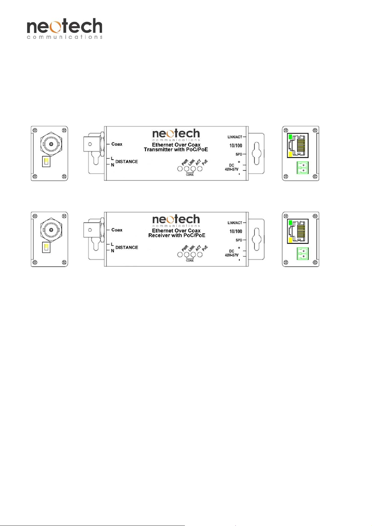
Product Overview
Transmitter
Receiver
Product Features
Complies with EN55022 Class A EMC Generic standard immunity.
Operates transparent to higher layer protocols.
One Ethernet port (RJ-45 connector): 10/100Mbps-Full/Half-duplex, Auto-negotiation, Auto-MDI/MDIX.
Complies with IEEE802.3 10Base-T and IEEE802.3u 100Base-TX standards.
Supports IEEE 8023af Power over Ethernet (PoE) Power Sourcing Equipment (PSE)
One Ethernet Extender port (BNC connector): Downlink: 36Mbps (max.); Uplink: 11Mbps (max.).
Maximum distance: 500m over Coax.
Provides BNC connector (female).
External AC to DC power adapter.
Operating voltage and max. current consumption: 0.8A @ 48VDC. Power consumption: 38.4W Max.
-10°C to 60°C (14°F to 140°F) operating temperature range.
Supports Wall Mounting installation.
Used as a stand-alone device.
1 V1.3
Page 2

FEC-11CP Series
Industrial 10/100Base-TX Ethernet over Coaxial Converter with PoE & PoC
Connecting to Power
The EoC converter is a plug-and-play device. The TX and RX supports two type of power supply.
Receiver (RX)
1. External Power Adapter - Con ne ct the sup plied AC to DC power adaptor to the receptacle on the rear panel of
the receiver, and then attach the plug into a standard AC outlet. The PWR LED will then be lit.
2. Power over Ethernet (PoE) - Connect the Ethernet cable from an Ethernet switch with PoE to the RJ45 of the
receiver, the PWR LED will then be lit. In this case, power adapter is not needed.
Transmitter (TX)
1. External Power Adapter - Con ne ct the sup plied AC to DC power adaptor to the receptacle on the rear panel of
the transmitter, and then attach the plug into a standard AC outlet. The PWR LED will then be lit.
2. Power over Coax (PoC) - When the coaxial cable is properly connected between the transmitter and receiver,
the transmitter can get the power from the remote receiver through the coaxial cable. The PWR LED will then be
lit. In this case, power adapter is not needed.
.
Connecting to Coax
Connect the coaxial cable to the BNC socket of the transmitter and receiver. If the transmitter and receiver are
properly connected and communicated with each other, the Link LED of the transmitter and receiver will be lit (ON).
The PoC LED of the receiver will be lit too.
Connecting to Ethernet
Connect the Ethernet cable from the IP camera to the RJ45 port of the transmitter. If the cable is properly connected,
the Act LED of the Ethernet port of the transmitter will start flashing. When the connected camera is a PoE IP
camera, the transmitter will supply power to the camera through the Ethernet port and the PoE LED will be lit.
Connect the Ethernet cable from the NVR or an Ethernet switch or similar equipment to the RJ45 port of the receiver.
If the cable is properly connected, the Act LED of the Ethernet port of the receiver will be lit.
The 10/100Base-TX Connector
The 10/100Base-TX Connections
The following lists the pinouts of 10/100Base-TX ports.
Pin Regular Ports PoE
1 Output Transmit Data + Unused
2 Output Transmit Data - Unused
3 Input Receive Data + Unused
4 Unused Positive (VCC+)
5 Unused Positive (VCC+)
6 Input Receive Data - Unused
7 Unused Negative (VCC-)
8 Unused Negative (VCC-)
The transmitter, as a Power Sourcing Equipment (PSE), use the data wires (alternative A) to supply power to the IP camera
( Power Device (PD)).
2 V1.3
Page 3

FEC-11CP Series
Industrial 10/100Base-TX Ethernet over Coaxial Converter with PoE & PoC
Coaxial Link Data Rate
There is a switch beside the Video connector. It can be used to control the distance of the coaxial link. If longer
distance is selected (switch position in L), the transmission distance can be reached up to 500m.
Position Distance
Downlink
Data Rate
(TX to RX)
NORMAL
LONG
300 m 36 Mbps 11 Mbps
500 m 21 Mbps 3 Mbps
LEDs
The LED indicators give you instant feedback on status of the EoC Transmitter & Receiver:
LEDs Colour State Indication
PWR Green
Link Green
Coax
ACT Green
Steady Power on, PWR
Off Power off
Steady The transmitter and receiver communicate and lock with each others.
Off The transmitter and receiver do not communicate or the coaxial cable is disconnected.
Flashing
Off No data transfer within the coaxial cable
Data transfer within the coaxial cable. The brightness depends on the data rate. The lower
the data rate, the dimmer is the LED.
stands for POWER
Uplink
(RX to TX)
Un-connected: Flash once, OFF five times
TX powed by 48V adaptor: flash twice, OFF four times
Over current : flash thrice , OFF thrice
Checking : flashing
PoC (RX) Green
PoE (TX) Green
Ethernet
Link/Act Green
Spd Yellow
Flashing
ON Power over Coax
Off RX is power under 48V
Steady Power is applied to the Power Device (PD)
Off A non-PoE device is connected or no Ethernet connection.
Steady A valid Ethernet connection established
Flashing Transmitting or receiving Ethernet data, Act stands for ACTIVITY
Off Neither valid Ethernet connection established nor transmitting/receiving Ethernet data
Steady Ethernet Connection transferring at 100Mbps
Off Ethernet Connection transferring at 10Mbps
Manual Earth Green manual is available on our website www.neotechcomm.com.tw
3 V1.3
 Loading...