


NEOTECHA SIGHT GLASS SG / BALL CHECK VALVE KR
INSTALLATION AND MAINTENANCE INSTRUCTIONS
Before installation these instructions must be fully read and understood
CONTENTS
1 General information on the installation
and maintenance instructions ������������������ 1
2 Safety ���������������������������������������������������������� 1
3 Transport/Storage ������������������������������������� 3
4 Features ����������������������������������������������������� 3
5 Identification����������������������������������������������� 5
6 Installation ������������������������������������������������� 5
7 Commissioning ������������������������������������������ 7
8 Notes on dangers during installation,
operation and maintenance ���������������������� 7
9 Operation ���������������������������������������������������� 7
10 Servicing ����������������������������������������������������� 7
11 Cause and remedy of
operating faults ������������������������������������������ 7
12 Decommissioning �������������������������������������� 8
13 Disposal ������������������������������������������������������ 8
14 Customer service ��������������������������������������� 8
15 Validity of the Installation and
Maintenance Instructions ������������������������� 8
1 GENERAL INFORMATION ON THE
INSTALLATION AND MAINTENANCE
INSTRUCTIONS
These installation and maintenance
instructions contain the information necessary
for safe and correct installation and operation
of the valve in the prescribed manner� If any
difficulties are encountered during installation
or operation which cannot be solved with
the aid of the installation and maintenance
instructions, please contact the supplier/
manufacturer for more information�
These installation and maintenance
instructions comply with the relevant applicable
EN safety standards�
When installing the fitting, the operator or
the person responsible for the design of the
installation must ensure that applicable national
regulations are complied with�
The manufacturer reserves all rights to make
technical changes and improvements at any time�
The use of these installation and maintenance
instructions assumes that the user is qualified
to “Qualified Personnel” level�
Operating staff must be given appropriate
training in the operating and maintenance
instructions�
2 SAFETY
Please also read through these notes carefully�
2.1 General potential danger due to
a� failure to observe the instructions
b� improper use
c� insufficiently qualified personnel
2.2 Correct use
2�2�1 Area of application
SG
Sight glasses equipped with 2 large borosilicate
sight glasses and drip nozzle are valves which
facilitate the observation of highly corrosive,
hot liquids and gases over a range from the
smallest quantity to large volume flows� The SG
is suitable for vertical and horizontal mounting�
KR
Ball check valves with integral sight glass are
valves which facilitate a controlled retention
or isolation of highly corrosive, hot liquids and
gases� A special feature of the KR is the gas
tight seal� The soft elastomer seal inserted in
the body guarantees a perfect shut off for gases�
The interchangeable soft seal can be supplied in
various elastomers as far as Perfluorelastomer�
The KR is suitable for vertical and horizontal
mounting� When mounted horizontally, the
volume flow must be high enough to press the
ball into the seat via the guides�
SG / KR
All product-wetted components are
manufactured in PFA and PTFE materials�
The materials used for components subject to
pressure are GGG40�3, polyester coated and
borosilicate glass�
2�2�2 Method of operation
SG
The medium can flow through without
restriction in the working direction (direction
of arrow) and drip onto the drip nozzle� In the
opposite direction, it is not possible to observe
the smallest quantity�
KR
The medium can flow through without
restriction in the working direction (direction of
arrow)� Inthe opposite direction, the ball closes
the passage, as soon as sufficient pressure has
built up under the ball and pressed it into the
ball seat�
Emerson.com/FinalControl © 2017 Emerson� All Rights Reserved� VCIOM-01976-EN 17/04
NEOTECHA SIGHT GLASS SG / BALL CHECK VALVE KR
INSTALLATION AND MAINTENANCE INSTRUCTIONS
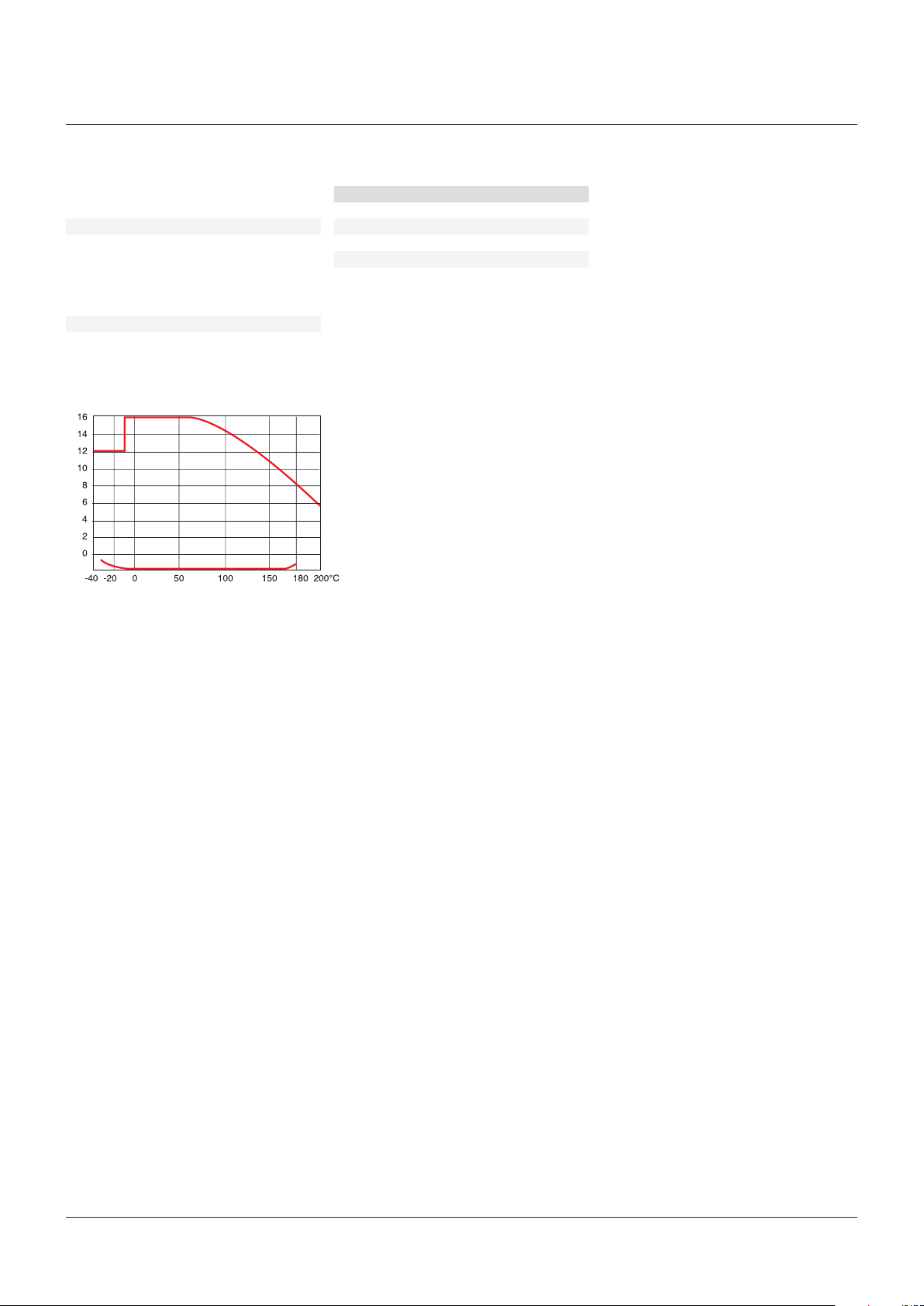
2�2�3 Performance data
Pressure range 16 bar - 20 Pa
Temperature range see table
Nominal diameters
Test pressure 1�5 x PN = 24 bar
DIN PN 16 ANSI 150 lbs
DN 25 1”
DN 40 1½”
DN 50 2”
DN 80 3”
PRESSURE-TEMPERATURE DIAGRAM
bar
20Pa
BALL CHECK VALVE FLOW VALUES
DN K
25 17�5 20�5
40 32�0 37�5
50 51�0 60�0
80 128�0 50�0
NOTES
Kv in m3 / hr
Cv in USG / min
Water Δp = 1bar
v
C
v
2�2�4 Usage restrictions
The product-wetted components must be
classified as resistant to the product to be
conveyed� Refer to appropriate literature
or consult the manufacturer or distributor
for advice�
2�2�5 Modification prohibition
Mechanical modifications to the valves
or the use of other manufacturers’
parts for repair purposes are not
permissible� Safety is not guaranteed if
this requirement is disregarded� Repair
work must only be carried out by the
manufacturer’s trained personnel�
2�2�6 Warning about foreseeable misuse
Valves and their accessories must not be
misused as climbing aids�
2�2�7 Duty to comply with the instructions for
operation, maintenance and servicing�
These operating instructions are part of
the delivery package and must be kept
clean and made accessible to the user�
2.3 Sources of danger
2�3�1 Chemical external
The valve bodies are made from
Spheroguss GGG40�3 coated with a
2-part polyester paint� The coating
can be attacked externally by strong
solvents, leading to corrosion of the
body� If damage of this nature occurs,
the effects on the environment should
be investigated and the damage to the
coating made good�
2�3�2 Mechanical
Excessive oscillation and vibration should
be avoided, to prevent the bolts loosening�
2�3�3 Electrical
If static charges can lead to explosions,
the valve must be earthed by means of
the earthing accessory�
Alternative: Use valves with electrically
conductive linings� Please contact your
supplier!
2�3�4 Thermal
Due to the range of operating
temperatures between -40°C and
+200°C, surface temperatures from -40°
to +200°C can be present on the valve
bodies� Suitable precautions should be
taken to protect against burns due to
high or freezing temperatures� Insulated
gloves must be worn during installation
and service work�
In case of fire, the mechanical strength of
the PFA coatings is no longer guaranteed
above 200°C�
2
NEOTECHA SIGHT GLASS SG / BALL CHECK VALVE KR
INSTALLATION AND MAINTENANCE INSTRUCTIONS
2.4 Requirements for the operator
This means people who are familiar with the
erection, installation, commissioning, operation
and maintenance of the product and have
appropriate qualifications relating to their
activities and functions, such as e�g�:
- instruction in and duty to comply with all
installation-related, regional and internal
works regulations and requirements
- training or instruction in accordance with the
Safety Standards for personal care and use of
appropriate safety equipment and protective
workgear, like e�g� personal protection
equipment (insulated gloves or similar),
suitable for the operating conditions�
Furthermore, these people must have read and
understood these instructions�
3 TRANSPORT/STORAGE
The valve is supplied with protective covers� Do not
remove the protective covers until immediately
prior to installation� They protect the PFA surface
from dust and mechanical influences�
3.1 Transport
- transport temperature -20°C to 65°C
- protect against external force
(impact, shock, vibration)
- do not damage the coating
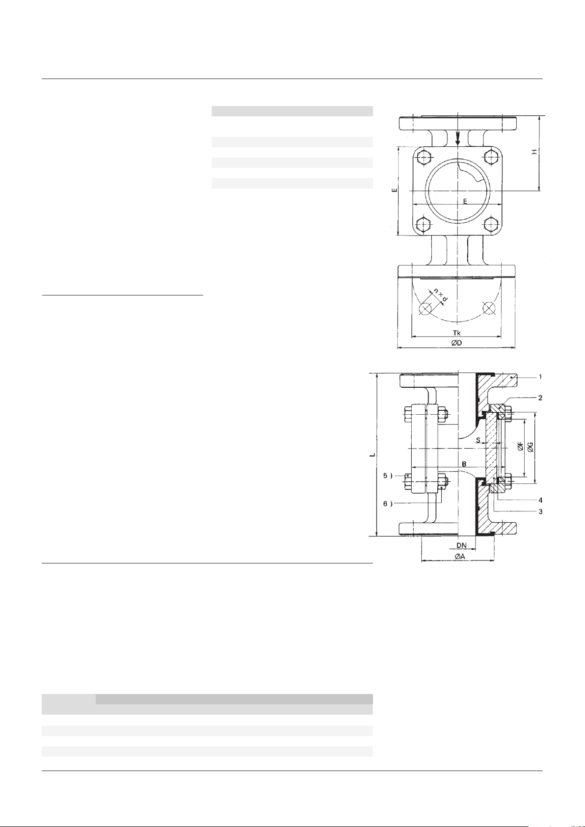
PARTS LIST
Item Description Material
1 Body GGG 40�3 polyester coated
PFA lined
2 Cover GGG 40�3 polyester coated
3 Sight glass Borosilicate glass DIN7080
4 Seal IT 150
5 Hexagon bolt Steel 8�8 galvanized
6 Hexagon nut Steel 8�8 galvanized
SIGHT GLASS
3.2 Storage
- storage temperature -20°C to 65°C, dry and
dust-free
-
a drying agent or heating is required in damp
storage areas to protect against condensation
3.3 Handling prior to installation
- do not remove the protective covers until
immediately prior to installation
- protect against the effects of weather, such
as dampness (or else use a drying agent)
- proper treatment prevents damage
4 FEATURES
Flange drillings: DIN2501 PN 16 or ANSI B16�5Class150
Face-to-face dimension: DIN3202/T1/F1 and F17
Bolted joint: Hexagon bolts steel 8�8 galvanized *
KR variants: PTFE solid ball as standard
PTFE hollow ball, floating, for overflow safety device
PTFE ball with steel core for exhaust backwash
Sight glass: Borosilicate glass
Blank cover: Steel cover with virgin PTFE liner
DIMENSIONS AND WEIGHTS
[2]
DN
DN (NPS) øA B E L
25 (1) 68 90 80 160 75�0 48 63 10 115 85 4x14 4�6
40 (1½) 88 118 105 200 92�0 65 80 12 150 110 4x18 9�1
50 (2) 120 134 125 230 107�5 82 100 15 165 125 4x18 12�2
80 (3) 138 196 190 310 145�0 150 175 25 200 160 8x18 25�0
[1]
H øF øG S øD TK
Weight
[2]
[2]
Nxd
kg
NOTES
1� Face-to face dimension according to
DIN3202/T1/F1 and F17
2� Flange drillings according to
ANSI B16�5Class150 on request
3
 Loading...