

Page 1

Best picture quality DVR
JPEG2000 Stand-alone DVR
0
INSTALLATION & SAFEGUARDS
All the safety and operating instructions should be read before the unit is operated.
Environment Condition for Installation
- To prevent electric shock or other hazard, do not expose units to rain, moisture, or dust.
- This unit should be located in an area with low humidity and a minimum of dust..
- Place this unit in a well-ventilated place and do not place heat-generating objects on this unit.
- This unit should not be located in an area where it is likely to be subjected to mechanical shocks.
Before You Start
- Ensure the power switch is in the OFF position prior to starting.
- Do not attempt to service this unit yourself as opening or removing covers may expose you to
dangerous voltage or other hazards.
- Installation should be performed by qualified service personnel only.
- This unit should be operated only from the type of power source indicated on the manufacturer’s
label and with the power supply included with the unit.
Notice
- Before initial configuration or operation you must first set the TIME/DATE, followed by
setting the unit to the FACTORY DEFAULT settings, lastly clearing the HDD. Please follow
these steps in order.
- Before installing a second HDD, ensure that the drive conforms to the specifications
listed on the specifications page at the end of this manual. When installing a second HDD,
set the drive to SLAVE. After installation, first reset the TIME/DATE, followed by resetting
the unit to the FACTORY DEFAULT settings, lastly clearing the new HDD.
- Pull the unit out of record mode prior to cutting power to the unit. Do this by entering the
setup menu, followed by switching the unit off. Powering off the unit while writing to the
disks can cause critical malfunctions. (ex: Recording Error, Playback Error, System Error)
- When you set the record type, you have to set the Record Configuration and also
Schedule Setup. This unit records as per the Record type & Schedule setup.
- The [REC] button on the front panel is for emergency record using highest image quality.
The lightning flash with arrowhead symbol within an equilateral triangle is intended to alert the
user of this equipment that there are dangerous voltages within the enclosure which may be of
sufficient magnitude to constitute a risk of electric shock.
The exclamation point within an equilateral triangle is intended to alert the user to presence of
important operating and maintenance(Servicing) instructions in the literature accompanying the
appliance.
Installation & Safeguards
Ver 1.3
Page 2
Best picture quality DVR
JPEG2000 Stand-alone DVR
1
Contents
Contents
16----------------------------------------------------------------Playback4-7.
16----------------------------------------------------------------Record4-6.
15----------------------------------------------------------------Zoom View5)
15----------------------------------------------------------------Freeze View4)
14----------------------------------------------------------------Display Configuration4-4.
14----------------------------------------------------------------Factory Default4-3.
13----------------------------------------------------------------System Log-in4-2.
13----------------------------------------------------------------Start-up DVR4-1.
15----------------------------------------------------------------PIP View3)
15----------------------------------------------------------------Sequencing Cameras2)
15----------------------------------------------------------------Full / Multiple View1)
15----------------------------------------------------------------Live View Setup4-5.
17
18
18
----------------------------------------------------------------
----------------------------------------------------------------
----------------------------------------------------------------
Search
PTZ Camera Operation
Data Back-Up
4-8.
4-9.
4-10.
13----------------------------------------------------------------OperationCHAP. 4
12----------------------------------------------------------------RS-232C ASCII-code8)
12----------------------------------------------------------------Connector Pin Assignment7)
11----------------------------------------------------------------Other External Device6)
11----------------------------------------------------------------VCR, Video Printer5)
10----------------------------------------------------------------Power4)
10----------------------------------------------------------------Monitor3)
10----------------------------------------------------------------Camera2)
9----------------------------------------------------------------HDD(Hard Disk Drive)1)
9----------------------------------------------------------------Detailed Installation3-2.
8----------------------------------------------------------------Installation Configuration3-1.
8----------------------------------------------------------------InstallationCHAP. 3
7----------------------------------------------------------------Rear2-2.
5----------------------------------------------------------------Front2-1.
5----------------------------------------------------------------Function of Each ButtonCHAP. 2
4----------------------------------------------------------------Package Contents1-2.
3----------------------------------------------------------------Features1-1.
3----------------------------------------------------------------Features & Package ContentsCHAP. 1
Page 3

Best picture quality DVR
JPEG2000 Stand-alone DVR
2
Contents
25----------------------------------------------------------------System Information8.
54----------------------------------------------------------------SpecificationsCHAP. 7
38
43
45
49
----------------------------------------------------------------
----------------------------------------------------------------
----------------------------------------------------------------
----------------------------------------------------------------
Remote Viewer Program
Back-Up CD Player
DDNS function
FAQ
6-2.
6-3.
6-4.
6-5.
31----------------------------------------------------------------DVR Network Configuration6-1.
29----------------------------------------------------------------RS-232C Setup2.
29----------------------------------------------------------------TCP/IP Setup1.
28----------------------------------------------------------------External Device5-6.
28----------------------------------------------------------------Back-Up5-5.
31----------------------------------------------------------------Network SetupCHAP. 6
30----------------------------------------------------------------Language Setup5-8.
30----------------------------------------------------------------FACTORY Default5-7.
29----------------------------------------------------------------Pan Tilt Zoom Setup3.
27----------------------------------------------------------------Holiday Setup3.
27----------------------------------------------------------------Schedule Setup2.
26----------------------------------------------------------------Record Configuration1.
26----------------------------------------------------------------Record Setup5-4.
25----------------------------------------------------------------Password Setup7.
25----------------------------------------------------------------Buzzer Setup6.
24----------------------------------------------------------------Alarm Setup5.
24----------------------------------------------------------------Interval Setup4.
22----------------------------------------------------------------Camera Setup3.
22----------------------------------------------------------------TIME/DATE Setup2.
21----------------------------------------------------------------HDD Management1.
21----------------------------------------------------------------Configuration5-3.
20----------------------------------------------------------------Monitor Setup2)
20----------------------------------------------------------------Screen Display1)
20----------------------------------------------------------------Display Setup5-2.
19----------------------------------------------------------------Entering the Menu5-1.
19----------------------------------------------------------------Set UpCHAP. 5
Page 4

Best picture quality DVR
JPEG2000 Stand-alone DVR
3
Live View
Real time display per camera
Auto Sequence
PIP (Picture in picture)
Digital Zoom
Display Freeze
Simple Playback mode
Simple PTZ camera control
Record
Variable Record resolution (For higher picture quality or higher recording speed)
Efficient Image Quality setup in 5 steps
Schedule Record / Holiday Record
Event Record (Alarm / Motion)
Emergency Record
Network
View Live and Playback images across IP network
Copy images across the network
Playback
Search & Playback by Date/Time, Event, Camera
Outstanding picture quality by JPEG 2000 compression algorithm (No mosaic effect)
Suitable for recording not only images but also text
Various steps in Forward Playback Speed (X1/16, X1/8, X1/4, X1/2, X2, X4, X16, X32, X64)
Various steps in Backward Playback Speed (X1/16, X1/8, X1/4, X1/2, X2, X4, X16, X32, X64)
Easy and convenient search by Jog Shuttle & Remote Controller
Data Back-Up
Simple Back-Up using built-in CD Writer (Back-up CD Player included in the package)
Network Back-Up using Remote Viewer program(Remote Viewer included in the package)
Supports bigger capacity of HDD (400GB or bigger)
Others
Multi-Language (English, Spanish, Portuguese, German, French, Italy, Japan, Chinese)
VGA support both TFT LCD monitor and CRT monitor (option)
Lock the system by Password
JOG / SHUTTLE
PAL/NTSC Auto detection
Control the unit by using Remote Controller
CHAP. 1 Features & Package Contents
CHAP. 1 Features & Package Contents
1-1. Features
Page 5
Best picture quality DVR
JPEG2000 Stand-alone DVR
4
CHAP. 1 Features & Package Contents
1-2. Package Contents
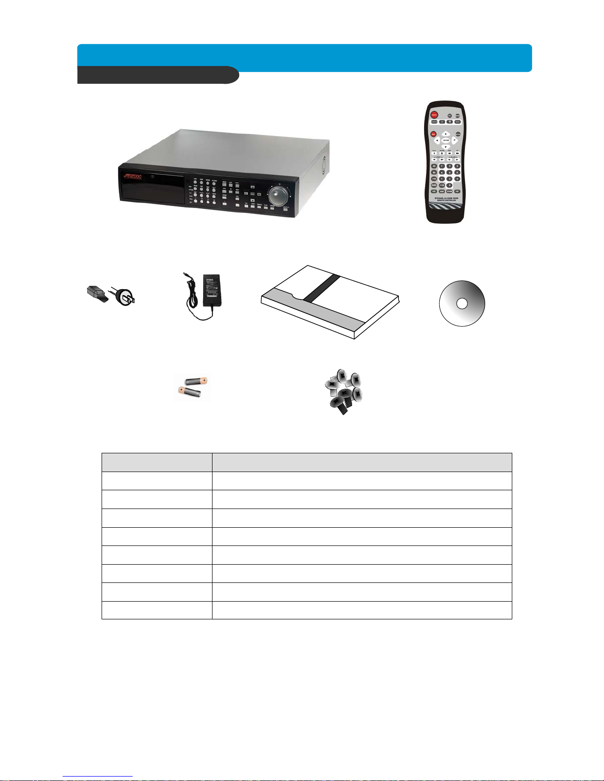
1. DVR Main Unit
2. Remote Controller
3. Power Cable
4. Power Adapter 5. User’s Manual
6. Software CD
7. Battery for remote controller 8. Bolts
For attaching Hard Disk Drive into DVR8. Bolts
Battery for remote controller7. Battery
Remote Viewer Software & Back up CD player6. Software CD
User’s Manual5. User’s Manual
12 V DC power supply to DVR main board4. Power Adapter
AC power supply to adapters for 12 V DC power3. Power Cable
DVR control 2. Remote Controller
STAND-ALONE DIGITAL VIDEO RECORDER1. DVR Main Unit
DescriptionPackage Contents
Page 6
Best picture quality DVR
JPEG2000 Stand-alone DVR
5
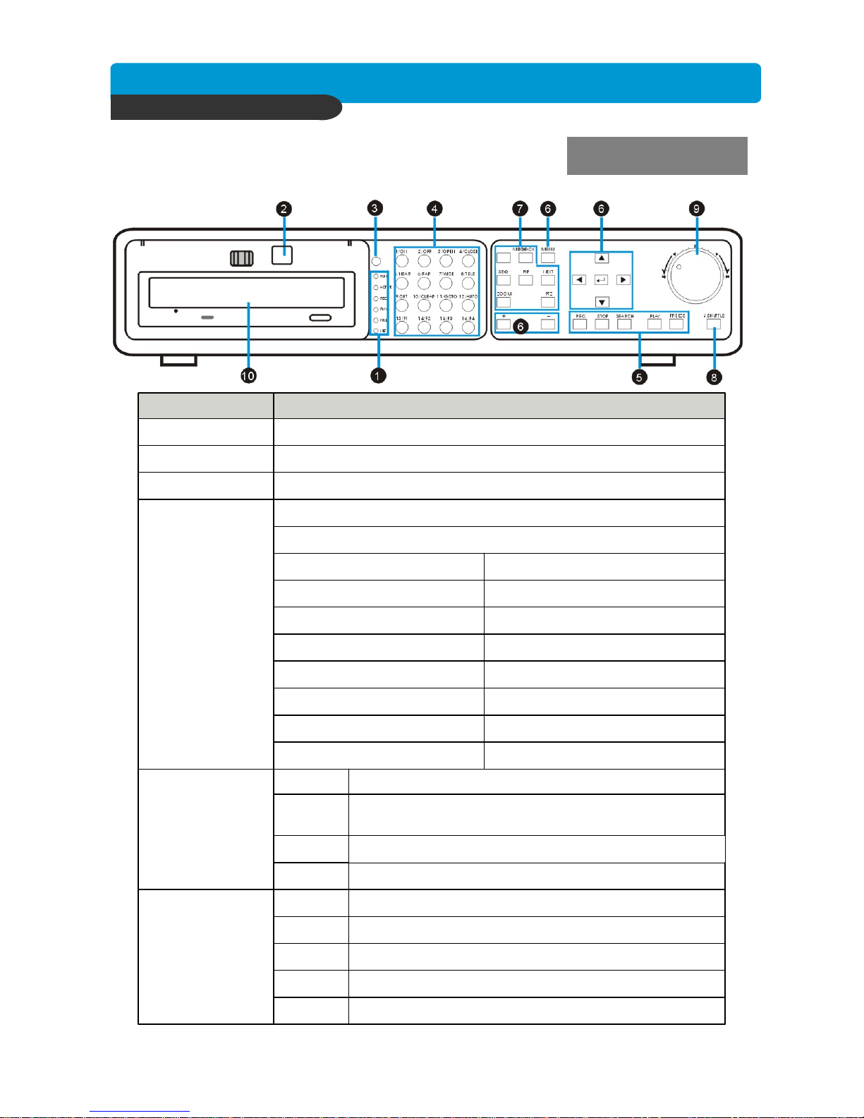
Reduce or increase the option value in the menu
Navigate in the menu
Move to next step
Selects each menu option
Set up for SYSTEM MENU or Use to exit the menu
Search recorded data on HDD
Playback of recorded data on HDD
Record Stop, Playback Stop, or Return to Schedule Record
from Emergency Record
Emergency Record at continuous, 60ips, SUPER FINE size
• F4 : USER 4
• F3 : USER 3
• F2 : USER 2
• F1 : USER 1
• AUTO : AUTO SCAN
• GOTO : GOTO PRESET
• CLEAR : CLEAR PRESET
• SET : SET PRESET
ENTER
MENU⑥ SETUP
SEARCH
PLAY
+ -
▲▼◀▶
NEXT
STOP
REC⑤ Record /
Playback
• TELE : ZOOM OUT
• WIDE : ZOOM IN
• FAR : FOCUS FAR
• NEAR : FOCUS NEAR
• CLOSE: IRIS CLOSE
• OPEN : IRIS OPEN
• OFF : LIGHT OFF
• ON : LIGHT ON
2. Control PTZ camera (Each button is assigned for each PTZ command)
1. Pressing this button will display a full screen image of that camera④ Camera
selection
&
PTZ camera
control
IR receiver③ IR
Firmware upgrade by connecting PC with latest firmware to USB port② USB Device
Shows status of operation① LED Lamps
FunctionName
CHAP. 2 Function of Each Button
2-1 FRONT
CHAP. 2 Function of Each Button
Page 7
Best picture quality DVR
JPEG2000 Stand-alone DVR
6
⑩ CD-RW
⑨ Jog Shuttle
⑧ Jog Shuttle
Control
Very easy and convenient search : Press J. Shuttle button, and images in
playback pause, and Jog and Shuttle makes it very easy and convenient to
search, forward or backward, fast and slow, as user want.
ACTIVE LED on : When J. SHUTTLE button is pressed
RUN LED on : While you operate Jog or Shuttle
Pressing Jog Shuttle button (Ready for use Jog/Shuttle)
: In playback mode, pressing J. SHUTTLE button make
images frozen.
Lock the key function
Auto camera image sequencing in full screen mode
Display in PIP (Picture in Picture) mode
Switch to split display
Freezing an Image
Zooming an image
On/Off for PAN/TILT/ZOOM control mode
Press this button first to control PTZ camera connected to
DVR unit via RS-485
Data Back-up using built-in CD writer
J.SHUTTLE
K.LOCK
SEQ
PIP
MODE
FRZ
ZOOM
PTZ⑦ LIVE View
Control
FunctionName
CHAP. 2 Function of Each Button
Page 8
Best picture quality DVR
JPEG2000 Stand-alone DVR
7
CHAP. 2 Function of Each Button
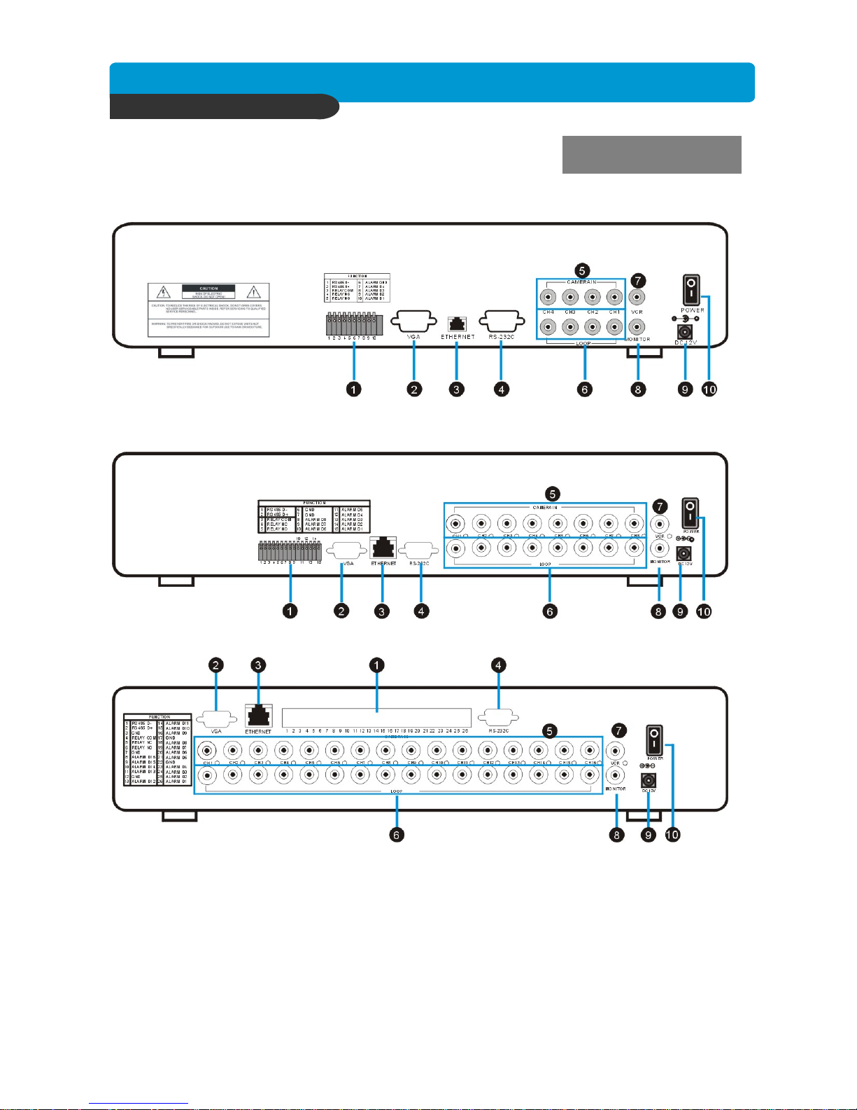
2-2. REAR
4 Channel
8 Channel
16 Channel
Page 9
Best picture quality DVR
JPEG2000 Stand-alone DVR
8
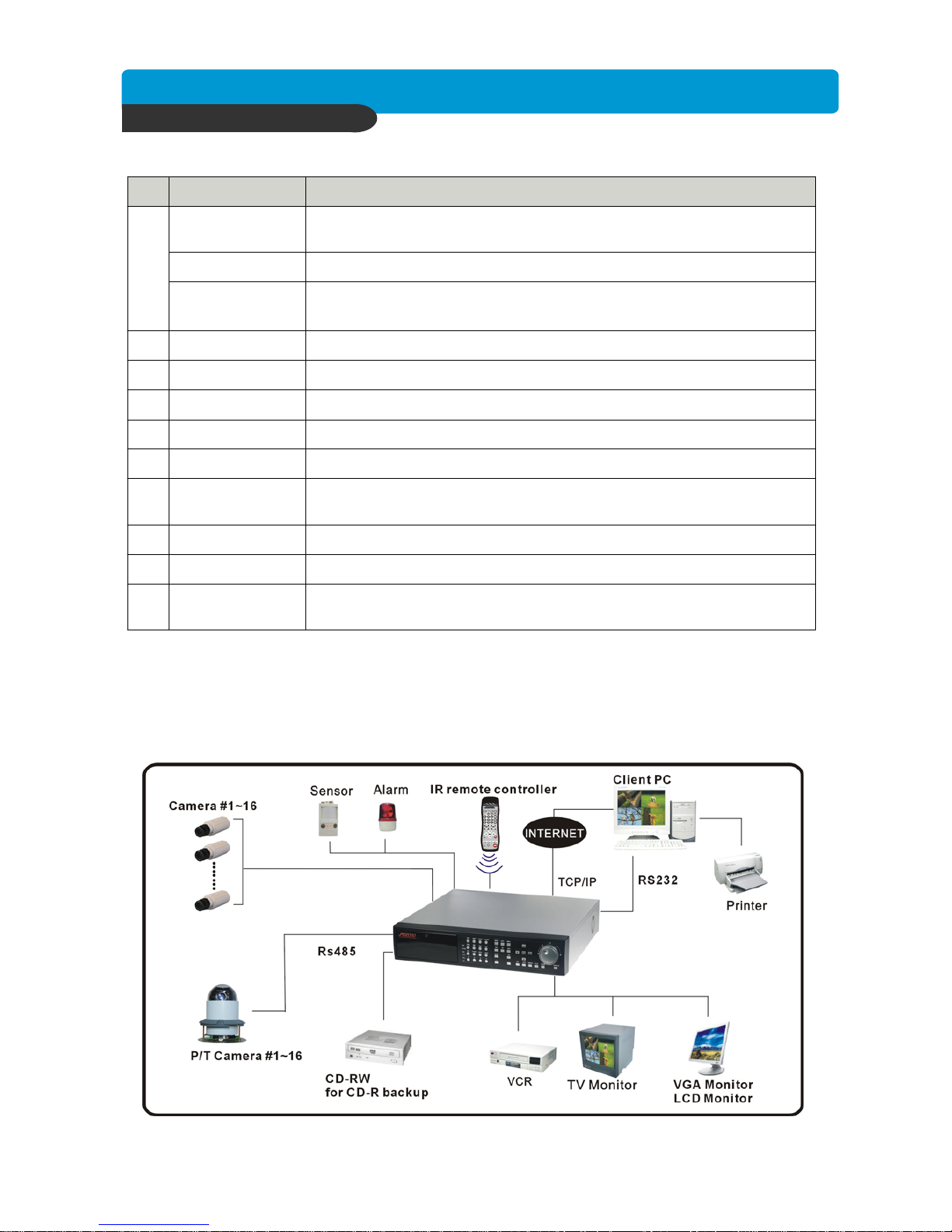
3-1. Installation Configuration
CHAP. 3 Installation
CHAP.3 Installation
10
9
8
7
6
5
4
3
2
1
MONITOR
Output
LOOP Output
CAMERA Input
RS-232C
ETHERNET
VGA
SENSOR Input
Connection with PTZ Camera or other external device using RS 485
interface (Pin 1: D- / Pin 2: D+)
RS 485
POWER
SWITCH
DC Power
VCR Output
Power ON/OFF
DC power input (DC12V, 10A )
Connection with VCR for analog backup
Connection with Composite Monitor
Camera loop out
Connection with camera
Connection to external device as PC using RS-232C to control the DVR
Connection to ETHERNET device
Connection to VGA Monitor (CRT type or TFT LCD monitor)
Sensor input terminal(Pin 6,7 : Ground,
Pin 8 ~15 : Sensor input)
Relay out terminal (Pin 3: Relay COM / Pin 4: NC / Pin 5 : NO) RELAY Output
FunctionName
Page 10
Best picture quality DVR
JPEG2000 Stand-alone DVR
9
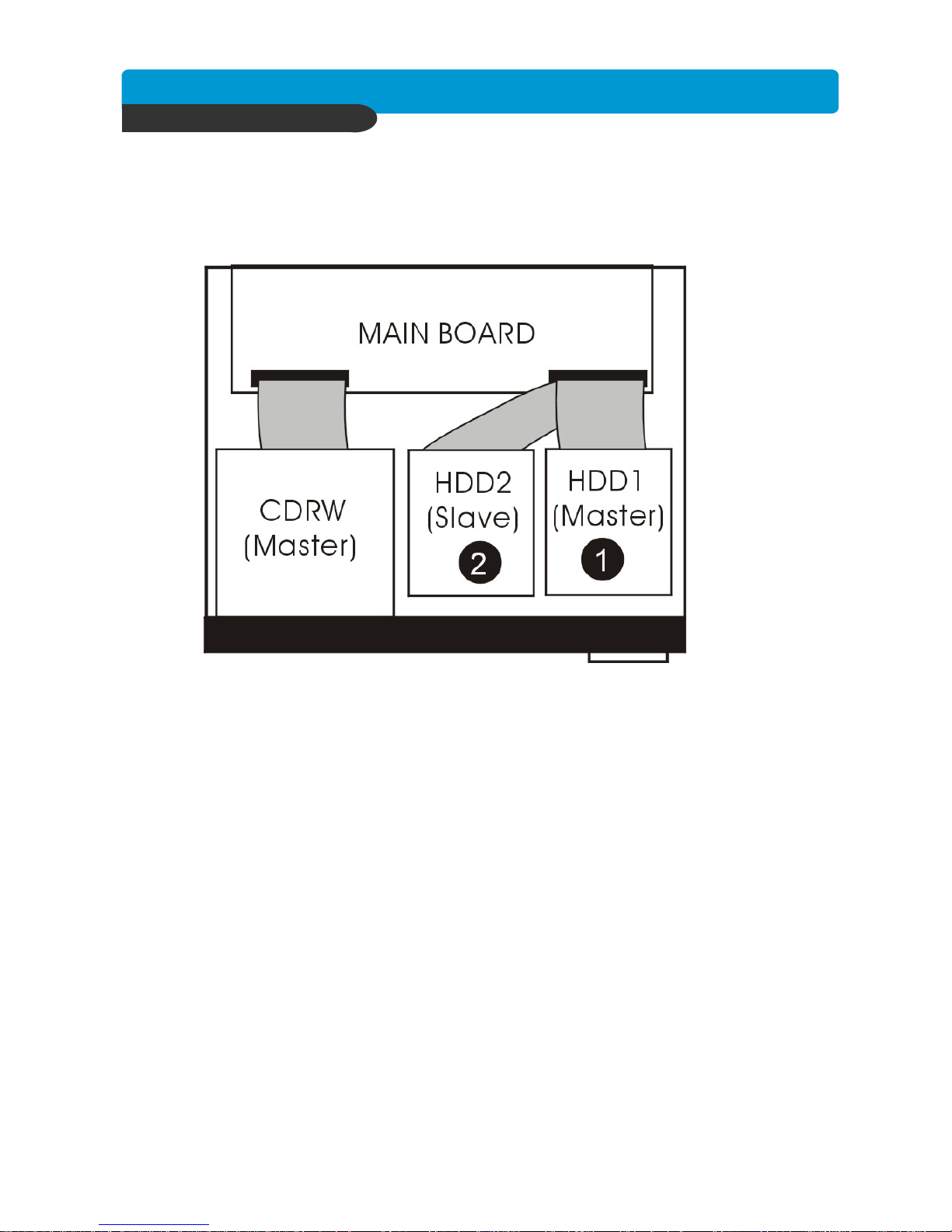
1) HDD
1. Connect Main Board and HDD using IDE cable and HDD power cable.
2. The jumper setting of HDD should be on Master if you install only one HDD.
3. The jumper setting of HDD1 should be on Master and HDD2 should be on Slave if you install
two HDDs.(Refer to the above figure)
4. Stick the HDD absorber (included in package) on the bottom of case and then install the HDD
on top of them by using the bolts (included in package).
5. Screws must be inserted from outside of the case bottom.
CHAP. 3 Installation
3-2. Detailed Installation
Page 11
Best picture quality DVR
JPEG2000 Stand-alone DVR
10
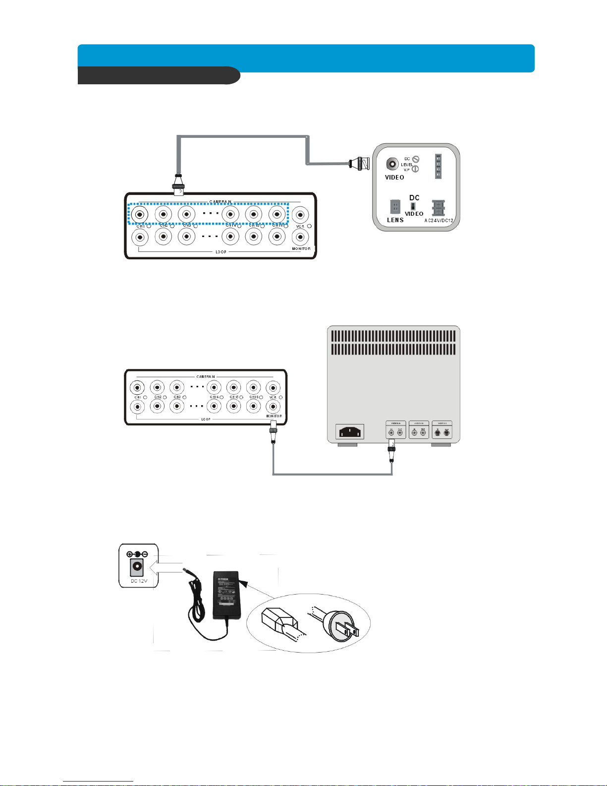
2) Camera
3) Monitor
Connect cameras to the camera input on rear panel of DVR marked CAMERA IN.
Connect the video output marked MONITOR to Video In of Main monitor.
4) Power
Insert the ADAPTER to the rear power socket of DVR.
ADAPTER specification: Input AC 110~240V / Output DC12V 10A
CHAP. 3 Installation
Page 12
Best picture quality DVR
JPEG2000 Stand-alone DVR
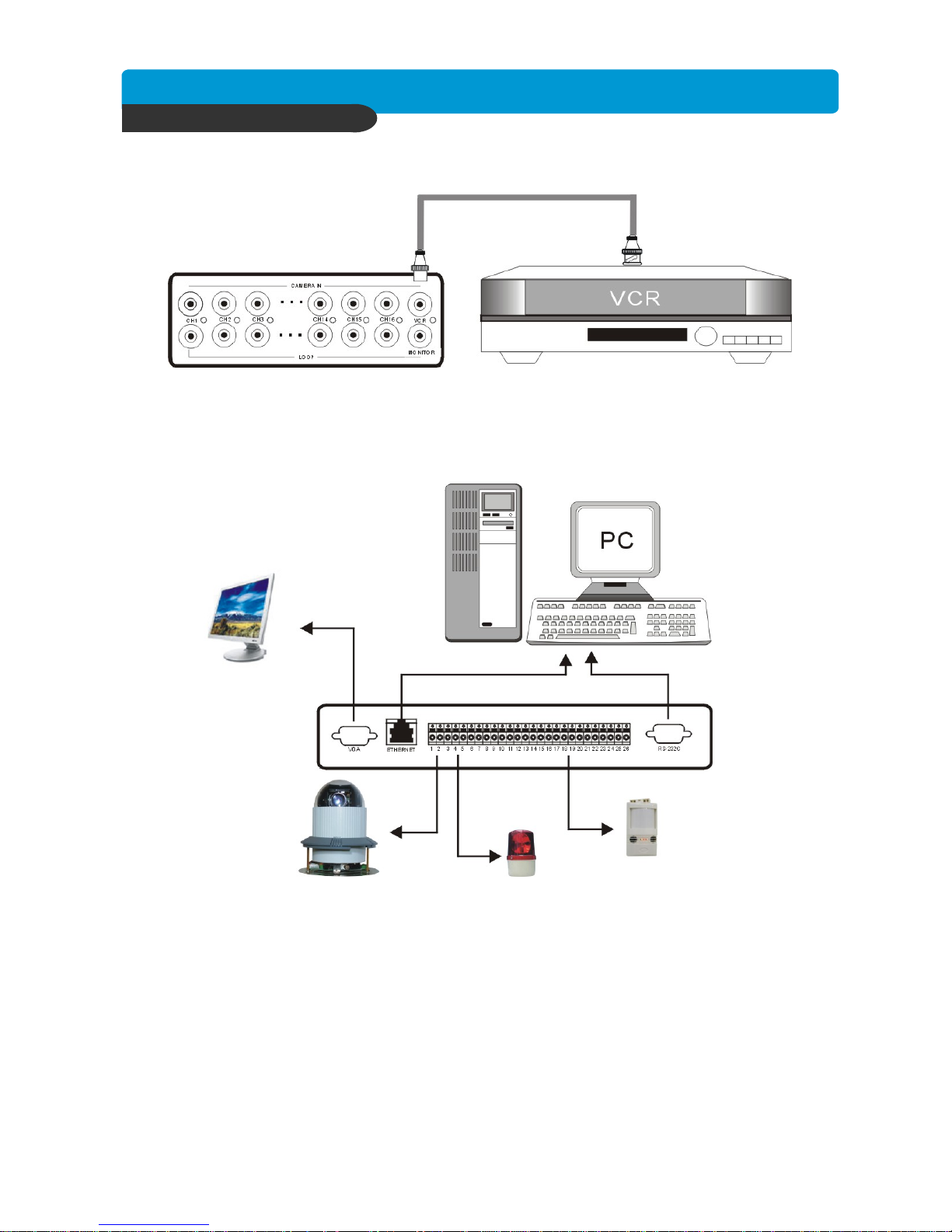
11
5) VCR
6) Other External Device
Connect VCR or VIDEO Printer to VCR out on the rear panel of DVR.
SENSOR
SIREN
PAN/TILT
CAMERA
VGA
MONITOR
RS-232C : Control DVR through RS-232C port by using PC.
RS-485 : Control external device like PTZ Camera (Pin 1, 2 at Terminal Block).
RELAY Output : Relay Output (Pin 3 ~5 at Terminal Block).
SENSOR Input : SENSOR Input (Alarm connection)
ETHERNET : Connection to LAN, WAN, Internet.
VGA : Connection with VGA monitor(CRT,TFT LCD).
Select VGA in DISPLAY SETUP menu before connection to VGA monitor.
Setting VGA option board (For both CRT type PC monitor or TFT LCD monitor)
CHAP. 3 Installation
Page 13
Best picture quality DVR
JPEG2000 Stand-alone DVR
12
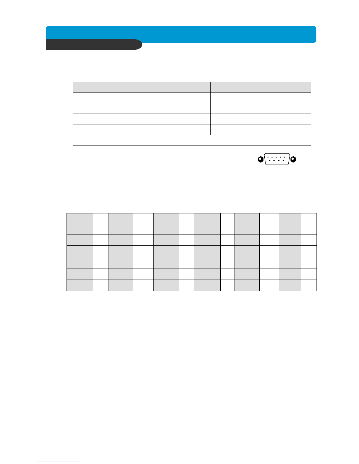
7) Connector Pin Assignment
8) RS-232C ASCII-code
Signal GroundGND5
9Data Terminal dataDTR4
RS232C: Rx/Tx dataCTS8Transmit dataTxD3
RS232C: Rx/Tx dataRTS7Receive dataRxD2
Data Set ReadyDSR6Data Carrier DetectDCD1
DescriptionNODescriptionNo
Com m Port
RS-232C
1 5
6 9
’@’
CH12
‘5’
CH5
‘L’
J.SHU
‘>’
+
‘U’
UP
’!’
CH11
‘4’
CH4
‘Q’
SEQ
‘<‘
-
‘M’
MENU
’#’
CH13
‘6’
CH6
‘C’
KLOCK
‘T’
PTZ
‘J’
DOWN
’0’
CH10
‘3’
CH3
‘I’
PIP0x0dENTER
‘E’
SERCH
’^’
CH16
‘9’
CH9
‘2’
CH2
‘D’
MODE
‘N’
NEXT
‘P’
PLAY
’%’
CH15
‘8’
CH8
‘1’
CH1
‘F’
FRZ
‘K’
RIGHT
‘S’
STOP
’$’
CH14
‘7’
CH7
‘Y’
QPLAY
‘Z’
ZOOM
‘H’
LEFT
‘R’
REC
Following ASCII-Codes(Hexa-Code) are for programmers who want to control DVR unit
via the RS232C Port using keyboard of PC.
All ASCII-Code is 1 Byte.
CHAP. 3 Installation
Page 14

Best picture quality DVR
JPEG2000 Stand-alone DVR
13
4-1. Start-up DVR
CHAP. 4 Operation
Before turning on the DVR be sure that everything is firmly connected. Turn on the DVR and g
o to the Menu using the relevant Login Password and you will then see the System Setup Screen.
You may proceed by referring to the related chapters describing the various functions.
4-2. System Log-In
DVR LOG-IN
ENTER PASSWORD : _ _ _ _ _ _ _ _
INPUT YOUR OWN PASSWORD
TO EXIT, PRESS [MENU]
1) To enter into the setup menu, press the [MENU] button.
2) Enter password with channel number button
from No.1 to No.10 on the front of the DVR unit.
(Maximum of 8 digits are available)
3) After inputting the password, press the [ENTER] button.
Administrator :
If the password entered matches previously set password, “ LOGIN ADMIN” message appears and
you can enter into SYSTEM SETUP.
If the password entered does not match previously set password, the DVR unit goes back to live
display mode.
Factory default password is blank. For log-in, just press [MENU] button, followed by the [ENTER]
button.
-Factory default password
ADMIN : (NULL)
MANAGER : ‘ 1 ’
USER 1~USER8 : ‘ 2 ’ ~ ’ 9 ’
※ We recommend configuring a unique password as per the procedure in
SYSTEM MENU - CONFIGURATION - PASSWORD SETUP.
※ For security reasons, be sure to make note of your own password.
CHAP.4 Operation
Page 15
Best picture quality DVR
JPEG2000 Stand-alone DVR
14
2005/JUN/03 pm 08:05:18
CAM-01
CAM-02
CAM-03 CAM-04
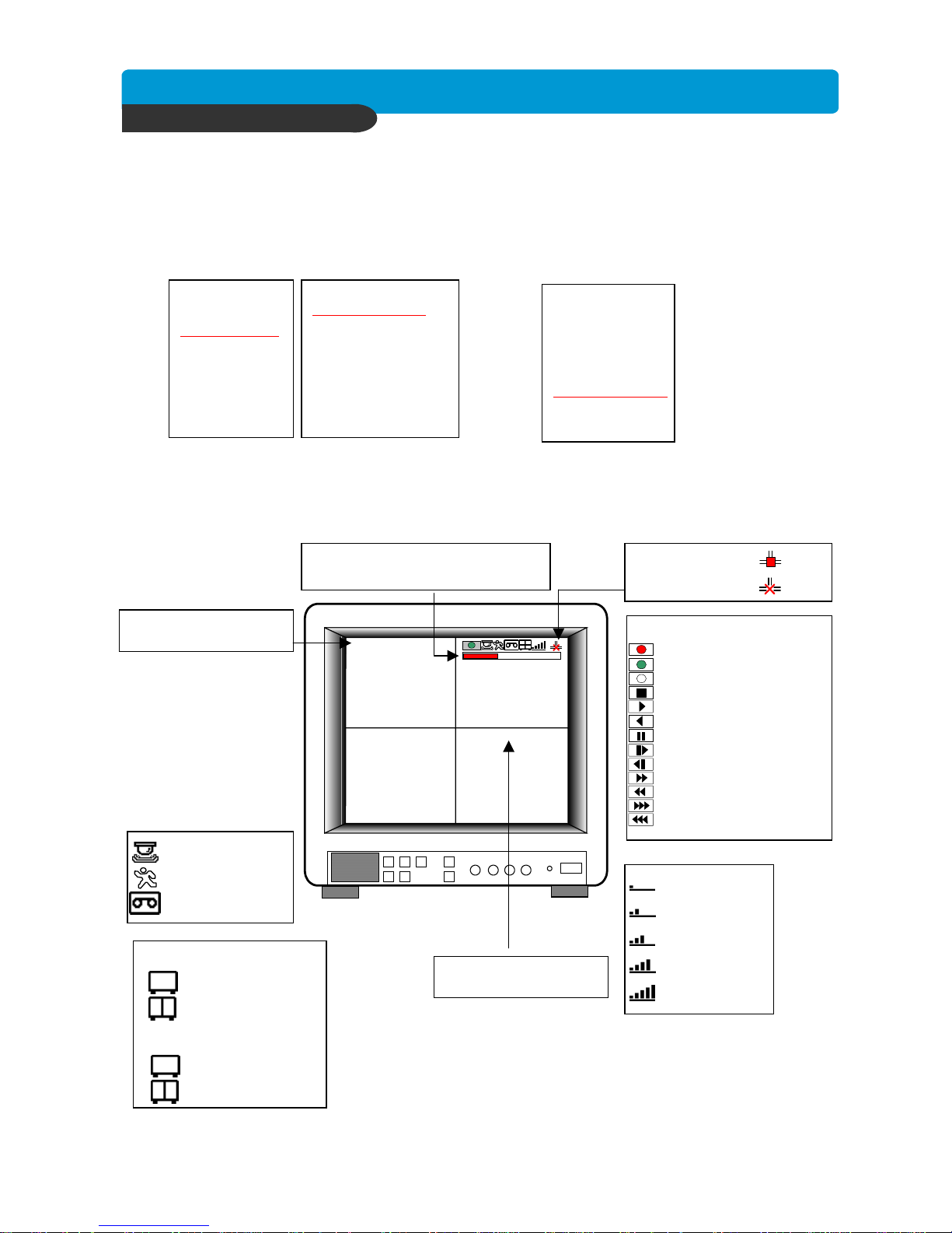
3. Status of DVR system
Emergency Record (Red)
Schedule Record (Green)
Temporary Stop (White)
Stop
Forward Playback
Backward Playback
Pause
1/16~1/2x forward playback
1/16~1/2x backward playback
2~16x forward playback
2~16x backward playback
16~64x forward playback
16~64x backward playback
4-4. Display Configuration
CHAP 4. Operation
1. Current Time & Date
2. Camera Title
ETHERNET status
HDD Status
In live mode : Amount of data recorded
In Playback mode : Amount of data played
LIVE Display
4-3. Factory Default
Before initial configuring or operation you must first set Time/Date, followed by setting the
unit to the FACTORY DEFAULT settings, lastly clearing the HDD. Please follow these steps
in order. Improper operation may result if this action is not taken.
DISPLAY SETUP
CONFIGURATION
REOCRD SETUP
BACK-UP
EXTERNAL DEVICE
FACTORY DEFAULT
LANGUAGE
HDD MANAGEMENT
TIME/DATE SETUP
CAMERA SETUP
INTERVAL SETUP
ALARM SETUP
BUZZER SETUP
PASSWORD SETUP
SYSTEM IMFORMATION
DISPLAY SETUP
CONFIGURATION
REOCRD SETUP
BACK-UP
EXTERNAL DEVICE
FACTORY DEFAULT
LANGUAGE
Refer to page 31.
Refer to page 22.
1. HDD CLEAR
2. FACTORY DEFAULT
ALARM Record
MOTION Record
CONTINUOUS Record
BASIC
NORMAL
ENHANCED
FINE
SUPER FINE
50/60 IPS @ 720x240
4 Channel
100/120 IPS @ 360x240
8/16 Channel
100/120 IPS @ 720x240
200/240 IPS @ 360x240
Page 16
Best picture quality DVR
JPEG2000 Stand-alone DVR
15
CHAP. 4 Operation
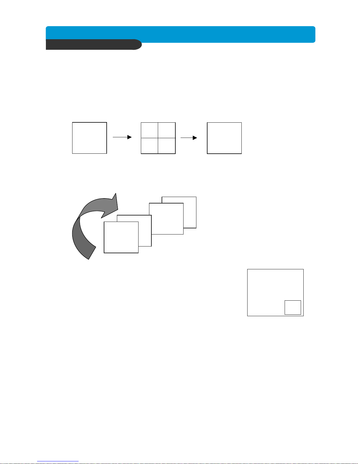
3) Picture in Picture(PIP View)
When it is in full screen display mode, you can see other camera in a small
window by pressingping [PIP].The other camera in small window is rotating
in sequence to next number of camera and you can set the rotating time
interval as per the procedure in SYSTEM MENU-CONFIGURATIONINTERVAL SETUP.
CAM-01
4) Freeze View
Full display mode : If you press the [FREEZE] button, the “F” character will be shown beside
camera title, and live image will be frozen.
Split display mode : If you press the [FREEZE] button, press the channel button which you
want to freeze.To release frozen image, press channel number of frozen
image again and press [FREEZE] button to exit FRZ mode.
5) Zoom View
In full screen, press the [ZOOM] button and move the Selection Frame using direction keys to the
area which you want to enlarge. And then press the [ENTER] button for 2-times enlarged picture.
To exit Zoom mode, just press [ZOOM] button again.
CH16
1) Full / Multiple View
Switch to multi-screen display by pressing [MODE]. For full image display, just press the channel button
which you want or [MODE] button again.
2) View in Sequence
Press [SEQ] button. It automatically displays full screen images in sequence.
4-5. Live View Setup
Full screen
Multi-screen
CH15
CH02
CH01
●
●
●
Full screen
[MODE]
[MODE] or Channel button
2
Page 17
Best picture quality DVR
JPEG2000 Stand-alone DVR
16
2005/JUN/03 pm 08:05:18
CAM-01
CAM-02
CAM-03 CAM-04
CHAP. 4 Operation
4-6. Record
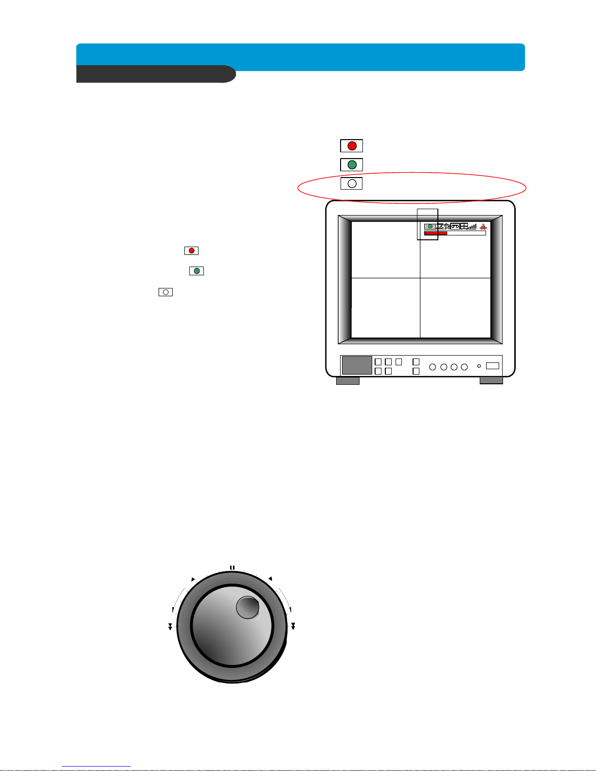
Recording mode set before delivery by manufacturer (Default recording mode) is Schedule Recording.
In this default recording mode, it records 24 hours/day continuously in weekday and on the weekend.
Once you press the [REC] button while you see live view, the record type is changed to Emergency Record mode.
- Emergency Record
Record type : CONTINUOUS, SUPER FINE quality,
4CH: 60 (50) ips at 720X240 (720x288)
8/16CH:120(100) ips at 720X240 (720x288)
- Schedule Record
Record and stop as set (time interval and
record type) in RECORD-SCHEDULE SETUP menu.
- Temporary Stop
Temporary Record stop as set in
RECORD-SCHEDULE SETUP menu.
On the screen
- Emergency Record
: Red Record Icon ( ) and Record LED is lit
- Schedule Record
: Green Record Icon ( ) and Record LED is lit
- Temporary Stop
: White Icon ( ) and Record LED is off
- Motion Record
: Record standby LED blinks
: Record LED is lit
※ While in Emergency Record mode, press [STOP],
[PLAY], [MENU], or [SEARCH] button to exit from
Emergency Recording mode and return to Schedule
Record mode.
※ For details, refer to the SYSTEM MENU – RECORD
SETUP (Page 27)
- This DVR unit does not record in following conditions ;
※ In Simplex mode, this unit does not record while entered in the menu or while it is in Playback mode.
※ No camera is connected
※ HDD is full and Overwriting is off in the Record Setup menu.
Emergency Record [RED]
Schedule Record [GREEN]
4-7. Playback
On record mode or stop mode, press [PLAY] button to play the recorded data in 1x speed.
For backward playback, press [PLAY] button again.
Use Jog/Shuttle to pause and control playback speed. To stop playback, press the [STOP] button.
Using Jog/Shuttle
press the [J.SHUTTLE] button in playback mode. The [ACTIVE] LED will be lit, and Jog/Shuttle is ready
for use. The [RUN] LED will blink whenever you operate the Jog/Shuttle.
For forward playback, turn the Shuttle right and turn Shuttle left for backward playback.
Turn Jog using your index figure to see picture by picture in forward or backward direction.
Operation of Shuttle is as follows.
1/4 x : 4 times slower than normal playback speed
1/2 x : 2 times slower than normal playback speed
1 x : Normal playback speed
2 x : 2 times faster than normal playback speed
4 x : 4 times faster than normal playback speed
16 x : 16 times faster than normal playback speed
64 x : 64 times faster than normal playback speed
If you want to keep the playback speed you selected using Shuttle, just hold the shuttle at that location for a few
seconds, and playback in speed you selected continues until you rotate Shuttle again.
Temporary Stop [WHITE]
J.SHU TTLE
RUN
ACTIVE
Page 18

Best picture quality DVR
JPEG2000 Stand-alone DVR
17
CHAP. 4 Operation
4-8. Search
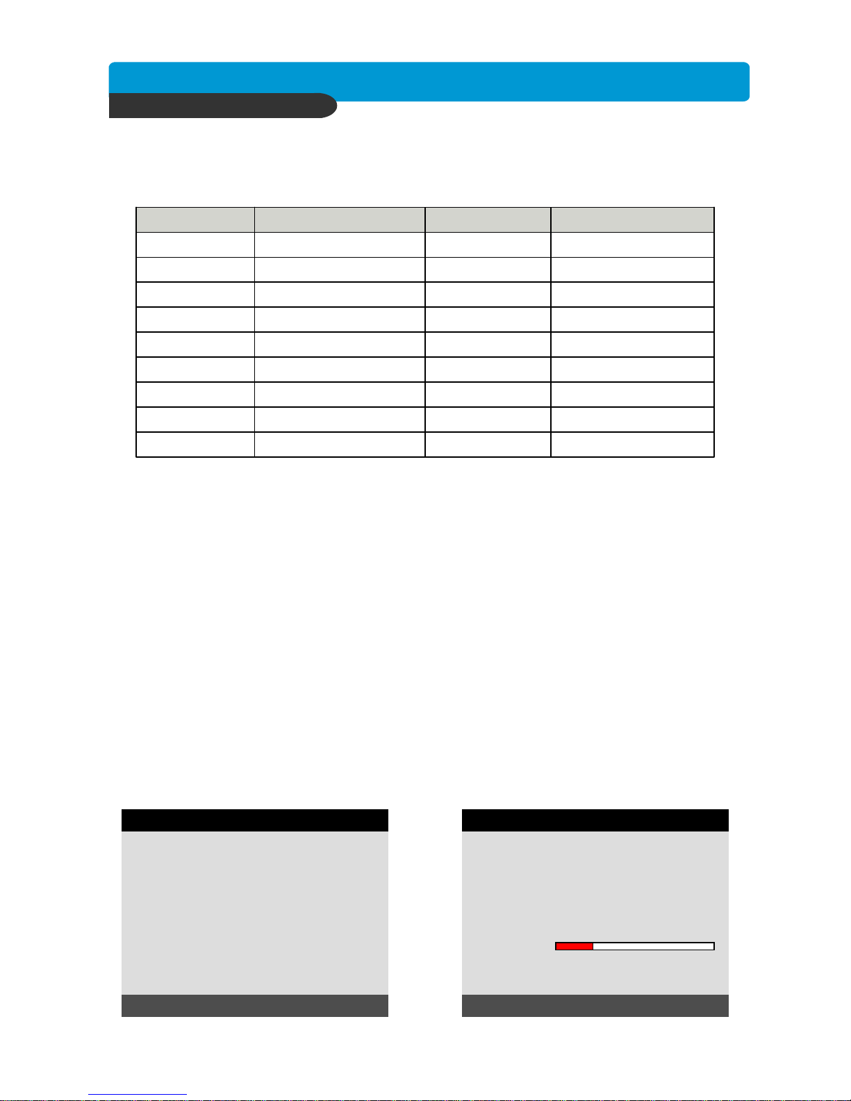
Press [SEARCH] button, and 3 different methods for searching recorded data are available as shown
in following SEARCH window. For selecting searching method, use direction key or Jog/Shuttle.
After selecting each search method, press [ENTER] button for playback.
1) SEARCH BAR
Search by percentage of total recorded data. It starts from image corresponding to set % of data
on the search bar.
2) TIME/DATE
Search by time & date. Playback starts from the time & date selected.
3) EVENT LIST
Search by event list (Motion, Alarm, Video Loss).
SEARCH
SEARCH BAR
TIME/DATE
EVENT LIST
SELECT MENU : ▲▼, & [ENTER]
RECORD SERCH BAR
[TARGET DATE/TIME]
020 %
SEARCH : [ENTER] , EXIT : [MENU]
TIME/DATE
[START] 2005/JUN/20 AM04:04:12
[ END ] 2005/JUN/20 PM08:12:23
INPUT DATE/TIME
2005/JUN/07 AM04:04:12
SEARCH : [ENTER] , EXIT : [MENU]
SEARCH page SEARCH BAR page
TIME/DATE page EVENT LIST page
EVENT LIST
SEARCH : [ENTER] , EXIT : [MENU]
-- : -- : --
-- : -- : --
-- : -- : --
-- : -- : --
-- : -- : --
-- : -- : --
-- : -- : --
---- / - -/ --
---- / - -/ --
---- / - -/ --
---- / - -/ --
---- / - -/ --
---- / - -/ --
---- / - -/ --
----
----
----
----
----
----
----
--
--
--
--
--
--
--
TIME/DATEEVEN
T
001/000CH
SELECT : JOG SHUTTLE
SELECT : ef, EDIT : + -
Page 19
Best picture quality DVR
JPEG2000 Stand-alone DVR
18
CHAP. 4 Operation
4-9. PAN/TILT/ZOOM Camera Operation
Press [PTZ] button first for PTZ control mode. Numeric buttons from 1 to 16 and direction buttons are
assigned for each PTZ command, and user can control PTZ camera connected to DVR unit by
pressing any one of those 20 buttons, one after the other, as needed, and it is just like control by
separate PTZ controller.
PTZ commandButton
PAN LEFT
PAN LEFT
TILT DOWN
TILT UP
FUNCTION
PRESET AUTO
PRESET GOTO
PRESET CLEAR
RIGHT BUTTON
LEFT BUTTON
DOWN BUTTON
UP BUTTON
13/F1 ~ 16/F4
12/AUTO
11/GOTO
10/CLEAR
9/SET
8/TELE
7/WIDE
6/FAR
5/NEAR
PRESET SET
ZOOM OUT
ZOOM IN
FOCUS FAR
FOCUS NEAR
IRIS CLOSE4/CLOSE
IRIS OPEN3/OPEN
LIGHT OFF2/OFF
LIGHT ON1/ON
PTZ commandButton
4-10. Data Back-Up
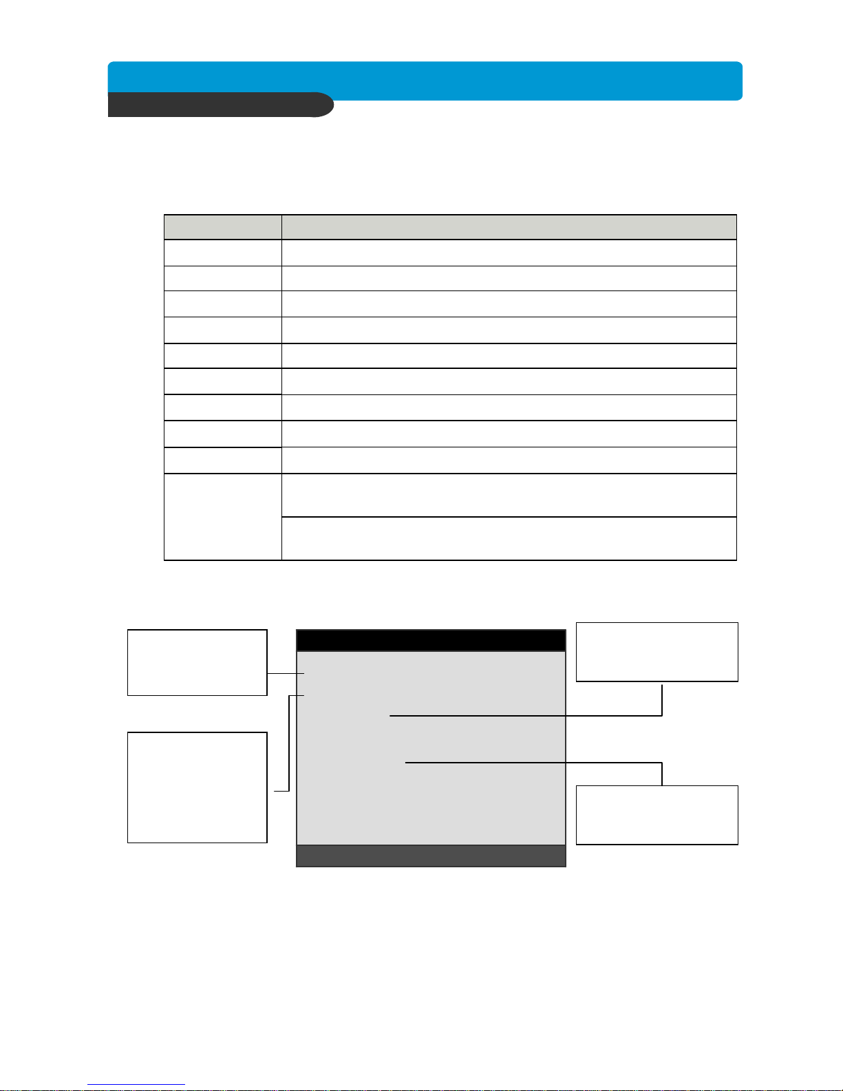
Enter into SYSTEM MENU-BACKUP-CDR SETUP.
1) Insert empty CD-R media into CD writer and select the start time & date from which you want to back up.
※ The START & END time / date in HDD sub-menu only shows start and end of recording.
This is not selectable and editable.
※ 700MB on CD-R sub-menu represent size of CD-R media inserted.
2) To set start time of back-up and back-up data size, press the [ENTER] button first on [START] or [SIZE]
sub-menu and adjust using [+] or [-] button and move using [LEFT] and [RIGHT] button for next
change. After setting the time & date and back-up data size, press the [ENTER] button again to exit.
※ End of back-up time will be calculated automatically as per start time & date and the back-up
data size you set.
※ User can select the back-up data size (size of back-up data from start of back-up) on [SIZE] item but
END of back-up time is automatically determined by DVR system.
3) Press [ENTER] button on BURN sub-menu. DVR system starts burning CD.
4) When burning is completed, CD-R media will come out automatically. In the next CD back-up, start
time of CD-R shall be the end time of previous CD-back-up, and you can back-up from that for
continuous data back-up. If you need another backup, repeat the above procedure. To stop backup,
press the [MENU] button.
※ During burning CD, it’s impossible to cancel burning process.
5) User can verify the back-up CD on PC with BACK-UP CD PLAYER (Included in Package).
CD-R SETUP
HDD
[START] 2005/AUG/07 AM04:04:12
[ END ] 2005/AUG/08 PM08:12:23
CD-R
[START] 2005/AUG/07 AM04:04:12
[ END ] 2005/AUG/08 PM08:12:23
[ SIZE ] 000MB
BURN
SELECT MENU :cd, & [ENTER]
CD-R SETUP
HDD
[START] 2005/AUG/07 AM04:04:12
[ END ] 2005/AUG/08 PM08:12:23
CD-R 700 MB
[START] 2005/AUG/07 AM04:04:12
[ END ] 2005/AUG/08 PM08:12:23
[ SIZE ] 700 MB - > 700MB
BURN
CD-RW BURNING : IMAGE DATA.
SELECT MENU :cd, & [ENTER]
Page 20
Best picture quality DVR
JPEG2000 Stand-alone DVR
19
CHAP. 5 Set Up
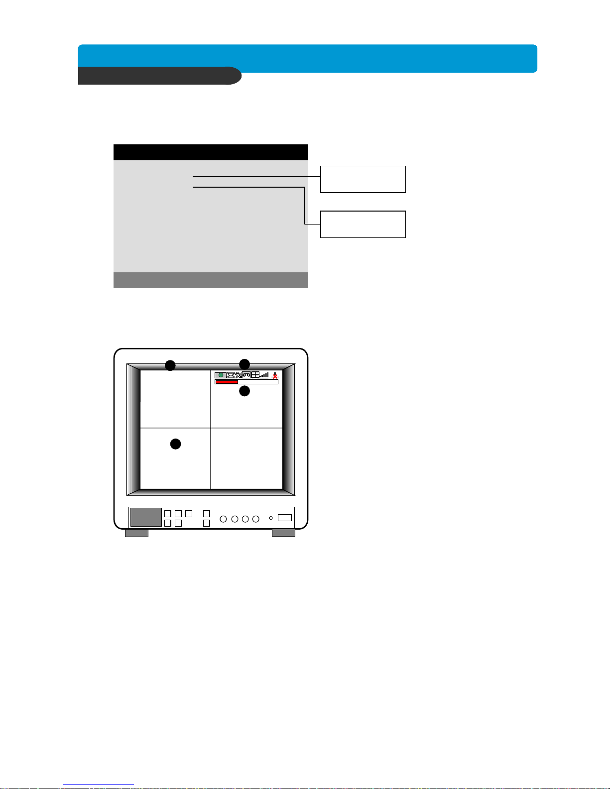
5-1. Entering into the Menu
Enter into SYSTEM MENU by pressping [MENU] button.
Shuttle left turning : Reduce playback speed / Decrease value
Shuttle right turning : Increase playback speed / Increase value
Increase the option valuePLUS [+]
Jog left turning : Move backward to next image / Decrease value
Jog right turning : Move forward to next image / Increase value
Jog Shuttle
Move down side
Move to upper side
Move to next page
Selection key, Move to sub-menu, change status (ON or OFF)
Enter into SYSTEM MENU, Move to previous menu, ESC
MINUS [-]
RIGHT
LEFT
DOWN
Reduce the option value
Move to the right
Move to the left
UP
NEXT
ENTER
MENU
FunctionButton
SELECT MENU : ▲▼, & [ENTER]
LANGUAGE ENGLISH
EXTERNAL DEVICE
FACTORY DEFAULT
RECORD SETUP
BACK-UP
CONFIGURATION
DISPLAY SETUP
SYSTEM MENU
SCREEN DISPLAY
MONITOR SETUP
HDD MANAGEMENT
TIME/DATE SETUP
CAMERA SETUP
INTERVAL SETUP
ALARM SETUP
BUZZER SETUP
PASSWORD SETUP
SYSTEM INFORMATION
RECORD CONFIGURATION
SCHEDULE SETUP
HOLIDAY SETUP
TCP/IP SETUP
RS-232C SETUP
PAN/TILT SETUP
SYSTEM MENU
CHAP. 5 Set Up
Page 21
Best picture quality DVR
JPEG2000 Stand-alone DVR
20
CHAP. 5 Set Up
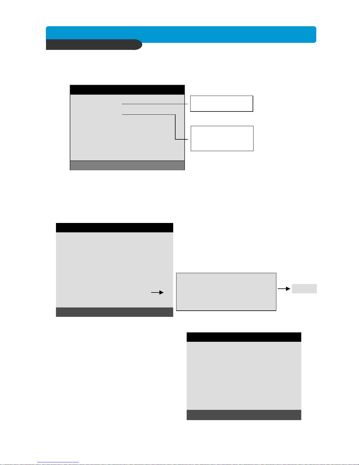
5-2. DIPLAY SETUP
Setting up parameters for monitor and display on screen.
Enter into SYSTEM MENU-DIPLAY SETUP.
SELECT MENU : ▲▼, & [ENTER]
SCREEN DISPLAY
MONITOR SETUP
DISPLAY SETUP
Setting up the screen display in LIVE mode and PLAYBACK mode.
Select the sub-menu which you would like to set using
direction buttons and then change ON/OFF with
[ENTER] button.
1. TIME/DATE : Display time & date
2. DVR STATUS : Display system setting status
3. REC/PLAY BAR : Display record / playback status
4. CAMERA TITLE : Display camera title
2) MONITOR SETUP
VGA SETUP : User have to select one the below option to optimize with the monitor using [+] [
−
]
button. After setting the below option, press [ENTER] button then the DVR unit will be
rebooted automatically.
- 800-600 / 60Hz : set when the VGA monitor(800x600 / 60Hz) is connected to DVR unit
- 640-480 / 60Hz : set when the VGA monitor(640x480 / 60Hz) is connected to DVR unit
- 800-600 / 75Hz : set when the VGA monitor(800x600 / 75Hz) is connected to DVR unit
- 640-480 / 75Hz : set when the VGA monitor(640x480 / 75Hz) is connected to DVR unit
COLOR BAR TEST : Necessary to adjust color tone of monitor.
※ NOTICE : In the very first operation of this DVR unit which has VGA card in it, when the user
turn on the DVR, it takes a few second to boot up for initialization of VGA.
1) SCREEN DISPLAY
LIVE
PLAYBACK
VGA SETUP
COLOR BAR TEST
2005/JUN/03 pm 08:05:18
CAM-01
CAM-02
CAM-03 CAM-04
1
2
3
4
Page 22
Best picture quality DVR
JPEG2000 Stand-alone DVR
21
CHAP. 5 Set Up
5-3. CONFIGURATION
Various parameters for system can be set in CONFIGURATION menu.
Enter into SYSTEM MENU-CONFIGURATION and press the [ENTER] button.
1) HDD MANAGEMENT
This page includes information about start and end of recording, location of recorded data, or location
of last playback on HDD. In addition, users can delete all the data on HDD.
SELECT MENU : ▲▼, & [ENTER]
HDD MANAGEMENT
TIME/DATE SETUP
CAMERA SETUP
INTERVAL SETUP
ALARM SETUP
BUZZER SETUP
PASSWORD SETUP
SYSTEM INFORMATION
CONFIGURATION
HDD CLEAR [ENTER], EXIT [MENU]
STATUS HDD DATE/TIME
---------------------------------------------------------------------BEGIN MASTER 2005/04/08
12:12:05
RECORD MASTER 2005/04/09
15:09:58
PLAY MASTER 2005/04/08
19:44:31
HDD STATUS NORMAL
HDD CLEAR IN USE
HDD SETUP
On the [HDD CLEAR] sub-menu, press the [ENTER]
button to delete all image data on HDD.
The system will ask password for verification.
After you clear all data on HDD, status of HDD CLEAR
changes from IN USE to EMPTY.
※ When you clear HDD, event list is deleted, too.
ENTER PASSWORD : ________
INPUT YOUR OWN PASSWORD.
TO EXIT, PRESS [MENU]
EMPTY
(2) HDD INFORMATION
This menu will show the physical information
of HDD in DVR.
: Maxtor 6Y080L0
: PIO-4
: 76GB
: 2005/04/08 12:08:56
: 2005/04/08 12:08:56
: AT5520026DT
: 240/120nsec
: 80GB
: 2005/04/08 12:08:56
: 2005/04/08 12:08:56
TO EXIT, PRESS [MENU]
[MASTER]
MODEL
SPEED
SIZE
START
END
[SLAVE]
MODEL
SPEED
SIZE
START
END
HDD INFORMATION
(1) HDD SETUP
Enter into SYSTEM MENU-CONFIGURATION-HDD MANAGEMENT and press the [ENTER] button.
HDD SETUP
HDD INFORMATION
CAMERA TITLE
CAMERA SETTING
CAMERA ACTIVE SETUP
MOTION SETUP
OK
Page 23

Best picture quality DVR
JPEG2000 Stand-alone DVR
22
CHAP. 5 Set Up
Set time and date of DVR system which is very
important for search with time and date of the event.
Time and date set by manufacturer is different from
local time of user, and user must set time and date
exactly in first operation. Set time & date using
direction buttons and [-][+] button or Jog shuttle
2) TIME/DATE SETUP
2005 / JUN /11
PM14:06:45
SELECT : ▲▼, CHANE VALUE : - +
YEAR
MONTH
DAY
HOUR
MINUTE
SECOND
TIME/DATE SETUP
3) CAMERA SETUP
(1) TITLE : Input Title of each camera. Move to channel you want to change using [LEFT] or [RIGHT]
direction button and then change the title using [-] [+] button. When modification is finished,
press the [ENTER] button. To exit to previous menu, press the [MENU] button.
(2) COLOR : Adjust image color
Move to each element using
[UP][DOWN] button and adjust using
[
-
] [+] button or Jog shuttle.
CHANNEL : Select camera to modify
BRIGHTNESS : Adjust image brightness (-32~ 31)
CONTRAST : Adjust color contrast ( -32 ~ 31)
SATURATION : Adjust color saturation ( -32 ~ 31)
HUE : Adjust color hue ( -32 ~ 31)
1
+0
+0
+0
+0
SELECT : ▲▼, CHANE VALUE : ◀▶
CHANNEL
BRIGHTNESS
CONTRAST
SATURATION
HUE
CAMERA SETUP
SELECT MENU : ▲▼, & [ENTER]
CAMERA TITLE
CAMERA SETUP
CAMERA ACTIVE SETUP
MOTION SETUP
CAMERA SETUP
[ENTER] :SELECT MODE
[◀ / ▶ / + / - ] : EDIT CAMERA TITLE
0123456789 .ABCDEFGHIJKLMNOPQ
RSTUVWXYZ ! #-[ ]*+ -,./ :<=>?@▶◀
CAMERA01 CAM -1
CAMERA02 CAM -2
CAMERA03 CAM -3
CAMERA04 CAM -4
CAMERA TITLE SETUP
Page 24
Best picture quality DVR
JPEG2000 Stand-alone DVR
23
CHAP. 5 Set Up
(3) CAMERA ACTIVE SETUP : With direction button, move to option to be changed, and press [ENTER]
button to select [ON/OFF]. If it is set at LIVE [OFF] and REC [ON], DVR
system records, but does not show live image of set channel.
- STATUS : Shows if image from a specific channel is coming for live display and recording. In normal
camera condition, it is ACTIVE, but LOSS is displayed when the cable is disconnected or
camera is not working.
- LIVE : Decides whether to show LIVE screen image or not.
- REC : Decides whether to record relevant channel or not.
ON
ON
OFF
OFF
ON
ON
OFF
ON
ACTIVE
ACTIVE
LOSS
ACTIVE
01
02
03
04
---------------------------------------------------------------------------
RECLIVESTATUS
SELECT : ▲▼, CHANGE VALUE : ◀▶
CH
CAMERA ACTIVE SETUP
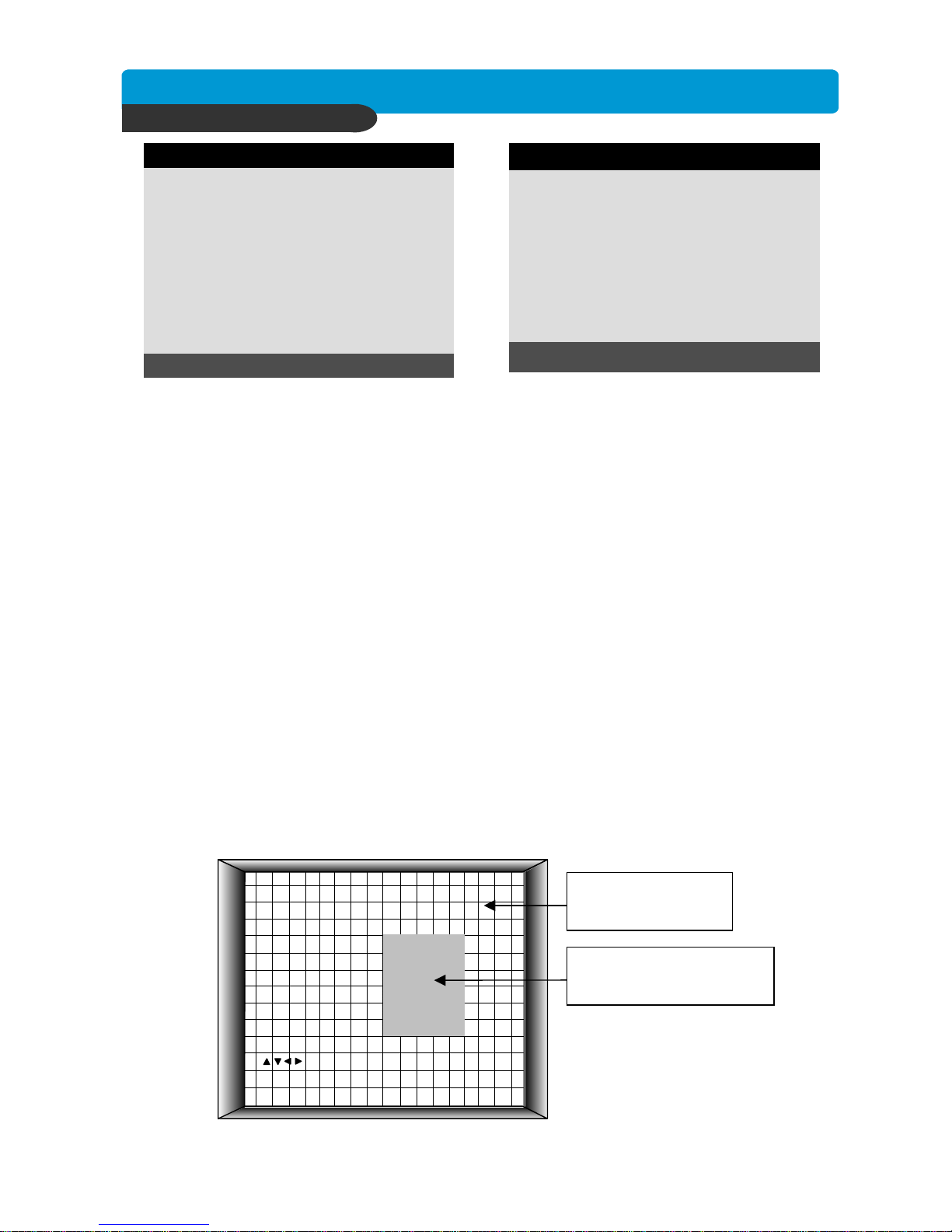
(4) MOTION SETUP: You can set sensitive of motion detection in 4 steps, detection window number, motion
detection area and others in relation to motion recording in this menu.
(4)-1. MOTION SETUP
- SENSITIVITY GRADE : Adjusts motion detection sensitivity. 1(LOW) ~ 4(VERY HIGH)
- MOTION DISPLAY TYPE : Showing cells with motion detected differently from cells with no motion .
- RECORD DURATION : Whenever motion is detected and it is set at Motion Recording mode, DVR
system records for RECORD DURATION from time motion is detected.
(1sec. ~ 99 sec.) (Default duration : 5 sec.)
(4)-2. MOTION MASK SETUP: Set motion detection area. Direction button is for moving and [ENTER]
button is for selection, and [MODE] button is for changing mode of MASK SETUP.
- CELL : Move to the location which you want to detect and then press the [ENTER] button.
Highlighted cell area means motion detection area.
- ALL ON : Set all cells as detection area. Use [ENTER] button to set.
- ALL OFF : Set all cells as no-detection area. Use [ENTER] button to set.
- BLOCK ON : Select detection area by block. Use [MODE] button and press [ENTER] button to set ON.
- BLOCK OFF : Select un-detection area by block. Use [MODE] button and press [ENTER] button to set ON.
01
01
OFF
05 SEC
SELECT ▲▼, PRESS ◀▶
CHANNEL
SENSITIVITY GRADE
MOTION DISPLAY TYPE
RECORD DURATION
MOTION SETUP
BLOCK ON [ 1 ]
[1/2/3/4] CHA NGE CHANNEL
[ ] MOVE CURSOR
[MODE] CHANGE EDIT MODE
[ENTER] EDIT, [MENU] E XIT
Highlighted Area
(Motion Detection Area)
Non-highlighted Area
(No Motion Detection Area)
Page 25

Best picture quality DVR
JPEG2000 Stand-alone DVR
24
CHAP. 5 Set Up
Set type of alarm sensors connected to DVR unit.
N.O represents Normal Open type and N.C Normal Close type.
5) ALARM SETUP
1) ALARM INPUT : Select type of alarm sensor connected to DVR unit (N.O or N.C).
Use direction button and [-] [+] button to set.
DISABLE represent not to use alarm sensor connected to DVR.
2) DURATION : Set the duration of alarm when an ALARM is activated. (0 sec. ~ 300 sec.)
4) INTERVAL SETUP
Set the switching time interval for SEQ or PIP
function.(1 sec. ~ 99 sec.)
FULL SCREEN : set the sequencing switch time interval
in live full screen.
PIP SCREEN : set the sequencing switch time interval
of PIP window.
EVENT UPDATE TIME : Set the minimum time interval of event to be listed in EVENT LIST.
If EVENT UPDATE TIME is set at 20 sec, only following event happened
20 sec or more than 20 sec later previous event shall be listed in EVENT LIST.
SWICHING INTERVAL
: 01 SECEVENT UPDATE TIME
EVENT RECORD
: 01 SEC
: 01 SEC
FULL SCREEN
PIP SCREEN
SELECT ▲▼◀▶, & CHANGE : + -
INTERVAL SETUP
N.O ................................ NORMAL OPEN
N.C ................................ NORMAL CLOSE
....................................... DISABLE
CH1
N.O
005
SELECT : ▲▼, CHANE VALUE : + -
CHANNEL
ALARM INPUT
DURATION
ALARM SETUP
Page 26

Best picture quality DVR
JPEG2000 Stand-alone DVR
25
CHAP. 5 Set Up
7) PASSWORD SETUP
-Use [UP] and [DOWN] button to move to option
and [LEFT] and [RIGHT] button to set user ID.
The password must be consist of 1 to 8 digit
number. Just use numbers button from 1 to 10
on the front panel of DVR unit.
-To change password, user must input current
password and then input new password.
And input again new password to confirm.
- Default value
ADMIN : ‘ ‘ (NULL)
MANAGER : ‘1’
USER 1 : ‘2”
:
:
USER 8 : ‘9’
Set user ID and password.
※ Change the user PASSWORD in the first operation is recommended.
※ In case you forgot PASSWORD, contact dealer of DVR to get instruction to enter into menu to
set new PASSWORD.
8) SYSTEM INFORMATION
DVR system information including model number,
firmware version, hardware version, etc.
6) BUZZER SETUP
ON
ON
ON
ON
ON
SELECT : ▲▼, CHANGE VALUE : ◀▶
ALL
KEY BEEP
VIDEO LOSS
ALARM ACTIVE
MOTION DETECT
BUZZER SETUP
Set parameters for buzzer (On or Off).
Use direction button and [ENTER] button.
KEY BEEP : buzz when button is pressed.
VIDEO LOSS : buzz when video signal is lost.
ALARM ACTIVE : buzz when alarm is activated.
MOTION DETECT : buzz when motion is detected.
User can set all buzzers at On/Off at once
by set ALL at ON.
[◀- ▶] CHANGE USER ID
[K1-K10] INPUT PASSWORD
[ENTER] CHANGE PASSWORD
ADMIN
---------------------
---------------------
---------------------
TO EXIT, PRESS [MENU]
USER I D
USER PW
NEW PW
CONFIRM
PASSWORD SETUP
TO EXIT, PRESS [MENU]
MODEL ID DVRJ-04CH
S/W VERSION VER 1.02
H/W VERSION VER 1.0
PRODUCT ID
01S-2039-001008-KR-01
MASTER
Maxtor 6Y060L0
SLAVE
CD-R
SAMSUNG CD-R/RW SW-256B
SYSTEM INFORMATION
Page 27

Best picture quality DVR
JPEG2000 Stand-alone DVR
26
CHAP. 5 Set Up
5-4. RECORD SETUP
This is the most important configuration of the DVR.
Enter into SYSTEM MENU-RECORD SETUP
and press the [ENTER] button.
SELECT MENU : ▲▼, & [ENTER]
RECORD CONFIGURATION
SCHEDULE SETUP
HOLIDAY SETUP
RECORD SETUP
1) RECORD CONFIGURATION
ON
TRIPLEX
ENHANCED
120IPS 720*240
1/1X
1/1X
1/1X
SELECT MENU : ▲▼, & [ENTER]
OVERWRITE
MULTIPLEX
QUALITY
RESOLUTION
RECORD IN ALARM
RECORD IN MOTION
CONTINUOUS RECORD
RECORD CONFIGURATION
Use direction button to move and [-] [+] button to set value.
(1)OVERWRITE : Set overwrite or stop recording when the
HDD is full.
(2) MULTIPLEX : Set DUPLEX. Or TRIPLEX
- DUPLEX : The DVR stops recording while the DVR
enters playback either locally or remotely.
※ During the r emote co nne ction, the DVR keep s
recording if the client stays at the LIVE mode.
It stops recording when the client enters the
playback mode.
- TRIPLEX : The DVR keeps recording while the DVR
enters playback either locally or remotely.Under the
Triplex mode, the record and playback speed drops by
50% of the frame rate.
(3) QUALITY : Set record quality. Actually it is fixing data
size of image for each picture quality level
BASIC / NORMAL / ENHANCED / FINE / SUPER FINE
(4) RESOLUTION : Set recording resolution.
- 120 ips at 720x240 (720x288)
- 240 ips at 360x240 (360x288)
※ Images recorded in 360x240(360x288)
It is not possible to see those images in full screen
mode in playback.Recording in half or quad resolution
is recommended for higher recoding speed.
(5) RECORD SPEED : Set record speed of alarm/ motion/ continuous mode(or skip rate)
- 1/1x, 1/2x, ………. 1/999x record speed
- ex: 1/2x ) R->S->R->S… - ex: 1/3x ) R->S->S->R->S->S->R…
- ex: 1/4x ) R->S->S->S->R->S->S… ( R : RECORD S : SKIP )
Page 28

Best picture quality DVR
JPEG2000 Stand-alone DVR
27
CHAP. 5 Set Up
Users can set national holiday or holidays on
calendar to record just as setting for Sunday in
Schedule recording.
3) HOLIDAY SETUP
MODE : MONTH
< AUG > 000/100
SUN MON TUE WED THU FRI SAT
01 02
03 04 05 06 07 08 09
10 11 12 13 14 15 16
17 18 19 20 21 22 23
24 25 26 27 28 29 30
HOLIDAY SETUP
Use [MODE] button to select a month and direction
button to move to a day, and press [ENTER] button to
set a holiday. Then color of date shall be changed to
red, as Sunday.
※ The maximum holidays is 100 days.
2) SCHEDULE SETUP
Set recording type for each recording time interval for a day of the week (2 hours interval).
Use [MODE] button to select edit type and move to
the time interval of a day of the week you want to change.
Press [ENTER] button to select and use [+] or [
−
] button,
to change the record type. To go next page, use [NEXT]
button.
(1) SCHEDULE SETUP
Unless you selected other recording mode, DVR system records in Schedule Recording mode.
In SCHEDULE REC SETUP, you set type of recording for every time interval of 2 hours in each day of
the week. Schedule Recording set by manufacturer is recording continuously at its full recording
speed, and it means DVR system record continuously at 120 ips in total at 720x240 resolution.
To set Schedule Recording parameters, enter into SYSTEM MENU-RECORD SETUP-SCHEDULE SETUP
and Press the [ENTER] button.
THU
--C-
--C
--C
--C
--C
--C
TUE
--C
--C
--C
-- C
--C-
--C
SAT
--C
--C
--C
-- C
--C
-- C
1 / 2
FRI
--C
--C
--C
-- C
--C
--C
WED
--C-
--C
--C
-- C
--C
--C
MON
AM -
AM -
AM-
AM-
AM-
AM-
SUN
-M-
-M -
-M -
-M -
---
-- -
SELECT: ▲▼◀▶ & [NEXT],EDIT [+ -]&[MODE]
A:ALARM M:MOTION C:CONTINUES
00-02
02-04
04-06
06-08
08-10
10-12
SCHEDULE REC SETUP
※ MODE (Edit type)
CELL BY CELL : Set each time interval of a day of
the week
DAY OF THE WEEK : Set a day of the week at once
TIME SLOT : Set a time slot at once
ALL : Set page by page at once
CLEAR ALL: Clear page by page
※ Except when EMERGENCY record is enable, the DVR system records based upon the SCHEDULE
Record Setup.
※ DEFAULT record mode for each time interval of a day of the week set by manufacturer is
CONTINUOUS recording.
※ Record type :
After power on Schedule record
Exit from menu Schedule record
End of search or playback Schedule record
After pressing [STOP] button Schedule record
After pressing [REC] button Emergency record (Continuous recording at full recording speed)
(120(100) ips at 720x240(720x288))
MODE: CELL BY CELL
Page 29

Best picture quality DVR
JPEG2000 Stand-alone DVR
28
CHAP. 5 Set Up
5-5. BACK-UP
CD-R SETUP
HDD
[START] 2005/AUG/07 AM04:04:12
[ END ] 2005/AUG/08 PM08:12:23
CD-R
[START] 2005/AUG/07 AM04:04:12
[ END ] 2005/AUG/08 PM08:12:23
[ SIZE ] 000MB
BURN
SELECT MENU: ▲▼ & [ENTER]
User can back up the recorded data to CD using CD writer installed in DVR.
Refer to [START] and [END] of data on HDD and set copy from time, [START], and size of data
copied, [SIZE], and move to BURN and press [ENTER] button to start copy.
5-6. EXTERNAL DEVICE
Set parameters of external devices connected to DVR, like Ethernet, PTZ camera, RS-232C, etc.
Use direction button to move to sub-menu and Press [ENTER] button to set.
SELECT MENU : ▲▼, & [ENTER]
TCP/IP SETUP
RS-232C SETUP
PAN/TILT SETUP
EXTERNAL DEVICE
System Status Messages :
- CD-RW DOOR CLOSE. CHECKING CD-R : Blank CD check
- INPUT BLANK CD : CD writer has no blank CD.
- CD-RW DOOR OPEN : Open CD-RW and insert blank CD –R media into CD drive.
- CD-R MEDIA IS DETECTED : Blank CD-R media has been inserted and detected. DVR system will
display size of blank CD-R.
After you set [START] time and [SIZE] in CD-R sub-menu and then select BURN, DVR system starts
copying images to CD and shows following message.
CD-RW BURINING START
CD-RW BURNING : LEAD-IN
CD-RW BURNING : IMAGE DATA
CD-RW BURING : CLOSE TRACK
CD-RW DOOR OPEN
When burning is completed, CD-R media will eject automatically.
To copy more images, repeat above process. In next process, [START] time in CD-R sub-menu shall
be [END] time in previous back-up, and you can copy images in series to many CDs as many as you
want.
CD-R SETUP
HDD
[START] 2005/AUG/07 AM04:04:12
[ END ] 2005/AUG/08 PM08:12:23
CD-R 700 MB
[START] 2005/AUG/07 AM04:04:12
[ END ] 2005/AUG/08 PM08:12:23
[ SIZE ] 700 MB - > 700MB
BURN
CD-RW BURNING : IMAGE DATA.
SELECT MENU: ▲▼ & [ENTER]
Page 30

Best picture quality DVR
JPEG2000 Stand-alone DVR
29
CHAP. 5 Set Up
2) RS-232C SETUP
User can control the DVR via RS-232C port.
Connect DVR to PC via RS-232C port and user
can control DVR using keyboard of PC.
This function is mainly for programmer who
wants to control DVR as part of many devices
connected to PC system, as in SI project.
3) PAN/TILT SETUP
It is to set parameters for PTZ camera connected to DVR unit. DVR unit already includes all
protocols of well-known PTZ cameras like PELCO D type PTZ camera, and user just select MODEL
and set other parameters to control this PTZ cameras, using operation buttons on the front panel of
DVR. If PTZ camera whose protocol is not incorporated into this DVR unit, user must input protocol
of this PTZ camera by himself. Using USB device port, user can upgrade protocol for PTZ camera.
SELECT : ▲▼, CHANGE VALUE : ◀▶
COMMAND SETTING Å PTZ camera set
SPEED SETTING Å PTZ speed set
PAN/TILT SETUP
1) TCP/IP SETUP
TCP/IP function enables user to see live pictures and
recorded pictures via the internet. To use the TCP/IP
option, user must assign IP ADDRESS & GATEWAY
& SUBNETMASK into DVR in TCP/IP SETUP MENU.
Also, user must install the Remote viewer program to
PC from which user want to access to DVR unit Via IP
network. For detail procedure of Remote viewer
program installation, refer to CHAP. 6 Software
program.(Remote viewer software).
Move to sub-menu you want to change and press
[ENTER] button to set value. Press direction button to
move and [+] and [-] button to set value.
576000
8
1
NONE
SELECT : ▲▼, CHANGE VALUE : ◀▶
SPEED
LENGTH
STOP BIT
PARITY
RS-232C SETUP
01
PELCO-D
000
2400 BPS
1 MSEC
PAN/TILT STOP
0.7
FF 00 00 00
00 00 00 00
SELECT : ▲▼, CHANGE VALUE : ◀▶
CHANNEL
MODEL
PTZ ID
BAUDRATE
CMD DELAY
COMMAND
LENGTH
CODE
COMMAND SETTING
1) CHANNEL : Select channel
2) MODEL : Select camera model (protocol type)
3) PTZ ID : Select ID
4) BAUDRATE : Select data transmission speed
5) CMD DELAY : Select command delay time
00-0A-A2-00-00-00
192.168.001.160
08000
192.168.001.001
255.255.255.000
MANUAL
SELECT MENU : ▲▼, & [ENTER]
MAC ADDRESS
IP ADDRESS
IP PORT
GATEWAY
SUBNET MASK
DHCP SETUP
TCP/IP SETUP
Page 31

Best picture quality DVR
JPEG2000 Stand-alone DVR
30
CHAP. 5 Set Up
5-7. FACTORY DEFAULT
Set the all system parameters as manufacturer first
set before delivery. It is a kind of system
initialization, and manufacturer recommend to do it
when you add new HDD or other changes in
system to make all system ready for normal
operation.
Use direction button to move and Press [ENTER]
button to change parameters. After move to RUN,
Press [ENTER] button for actual Factory Default
setting.
SELECT MENU : ▲▼, & [ENTER]
LANGUAGE ENGLISH
EXTERNAL DEVICE
FACTORY DEFAULT
RECORD SETUP
CONFIGURATION
DISPLAY SETUP
SYSTEM MENU
5-8. LANGUAGE SETUP
Press [+] / [-] button to select your language.
FACTORY DEFAULT
SELECT MENU : ▲▼, & [ENTER]
OFF
OFF
OFF
OFF
OFF
OFF
OFF
ALL
SCREEN DISPLAY
CAMERA COLOR SETUP
MOTION SETUP
PANTILT SERUP
SCHEDULE SETUP
CONFIGURATION
RUN
Page 32

Best picture quality DVR
JPEG2000 Stand-alone DVR
31
CHAP. 6 Network Setup
6-1. DVR Network Configuration
Now that you are familiar with the equipment and should be able to identify a router from a modem and a
Cat5 network cable from a telephone cable, we will proceed to determine the network scenario that fits
your current network.
Please call your provider to identify what type of service they are providing you. You will need to know
following ;
Upload speed – For your own knowledge for expected frame rates
Download speed – For your own knowledge for expected frame rates
Addressing – For determining what scenario you should follow
Router On Site or Just a Modem – For determining what scenario you should follow
※NOTE : If your provider is using PPPoE(usually DSL providers), you MUST have a router
installed on site and follow CASE C for DVR setup and access.
※PLEASE verify Internet access after installing any new equipment(routers, switches, modems, etc.).
If possible, use a PC on the network to verify that an Internet connection can be made and that all
current configurations on any equipment are up and working properly. Do this before doing ANY
configurations with the DVR. We are assuming that your current equipment is configured properly for
Internet access.
PC’s TCP/IP Setting
Before configuring the DVR, please fill out the information below if applicable ;
Choose any PC on your network and determine its TCP/IP settings;
IP Address :
(ex.192.168.1.5)
Subnet Mask :
(ex. 255.255.255.0)
Default Gateway :
(ex.192.168.1.1)
* For information on how to determine this information, please consult the FAQ page.
CHAP. 6 Network Setup
Next pages are several network scenar ios. Each one is labeled with a letter. Please identify
which scenario your current network falls within and follow the instructions for configuring and
accessing your DVR via TCP/IP.
The box below represents an area that you can’t control. If you are unable or do not have access
to your router for port forwarding. Please contact your provider and request them to forward a port
to the corresponding DVR IP address :
Page 33
Best picture quality DVR
JPEG2000 Stand-alone DVR
32
CHAP. 6 Network Setup
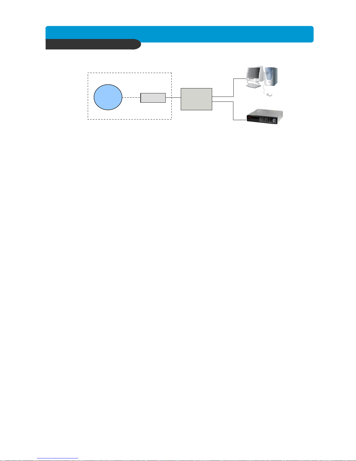
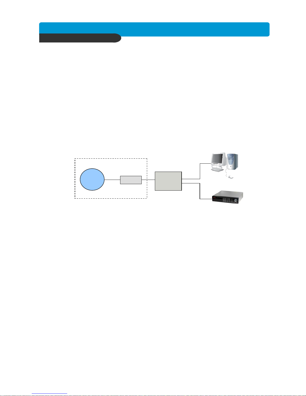
Case A : Single Static IP w/Personal Router
Accessing the DVR using the Remote Software for CASE A
Configure the DVR as follows :
1. Set the DVR to MANUAL for the TCP/IP settings. Do not use DHCP SETUP for this
application or verify that DHCP SETUP is set to MANUAL.
2. IP ADDRESS : assign it a private IP address(ex : 192.168.0.105)
a. You need to assign the DVR an IP address just as you would a PC.
b. The IP address you assign must be unique to your local network as well as “match”
your local network. For information on how to choose a unique IP that matches your
network, consult the FAQ.
c. The IP address you assign must be a private IP address. For information on what a
private IP address is, consult the FAQ.
d. When configuring the DVR’s IP address information, the version of firmware within
the units may display the IP addresses differently. For simplicity sake,
192.168.1.105 may have to be configured as 192.168.001.105
3. PORT NUMBER : 8000
a. 4 channel, 8 channel & 16 channel : This number is stated explicitly.
b. For most situations, please use the default 8000 for simplicity.
4. SUBNET MASK : 255.255.255.0 (example)
a. Assign the DVR the same exact subnet mask as your PC.
5. GATEWAY : 192.168.0.1(example)
a. Assign the DVR the same exact gateway(or default gateway) as your PC.
6. Please DO NOT configure MAC ADDRESS or DHCP SETUP.
7. You will need to forward port 8000 through your router. Please forward port 8000 to the
IP ADDRESS you have assigned the DVR.
8. Your DVR is now ready for access.
* For detail information on the above, please consult the FAQ.
LOCALLY :
To access the DVR locally, that is from your local network on site from where the DVR
is installed. Open the remote viewing software and click on the “Settings” button.
As far as TCP/IP connectivity is concerned only 4 entries need to be made :
1. IP address : Input the IP address that you assigned the DVR. As in the above example
I would input the private IP address of 192.168.0.105
2. Port : 8000(this has to match what is configured in the router and in the DVR)
3. User ID : (always leave the default “ admin “)
4. Password : this must match what is configured in the DVR
a) 4,8,16 channel default : null(NO PASSWORD)
Internet
(ISP)
modem
Personal
Router
w/switch
PC
DVR
Phone line
Or CATV
Page 34
Best picture quality DVR
JPEG2000 Stand-alone DVR
33
CHAP. 6 Network Setup
REMOTELY :
To access the DVR remotely, that is from outside your local network, follow the above
directions for accessing locally, except for the IP address. For CASE A, you have received a
static IP from your Internet provider. That static IP address is what you must enter into the
software for connectivity to take place(NOT the IP of the DVR). Contact your provider if you
have misplaced the forms stating your static IP address. Since you are accessing the DVR
via a router, you must enter the router’s WAN IP address which is the exactly the same as
the static IP that you have received from your Internet provider.
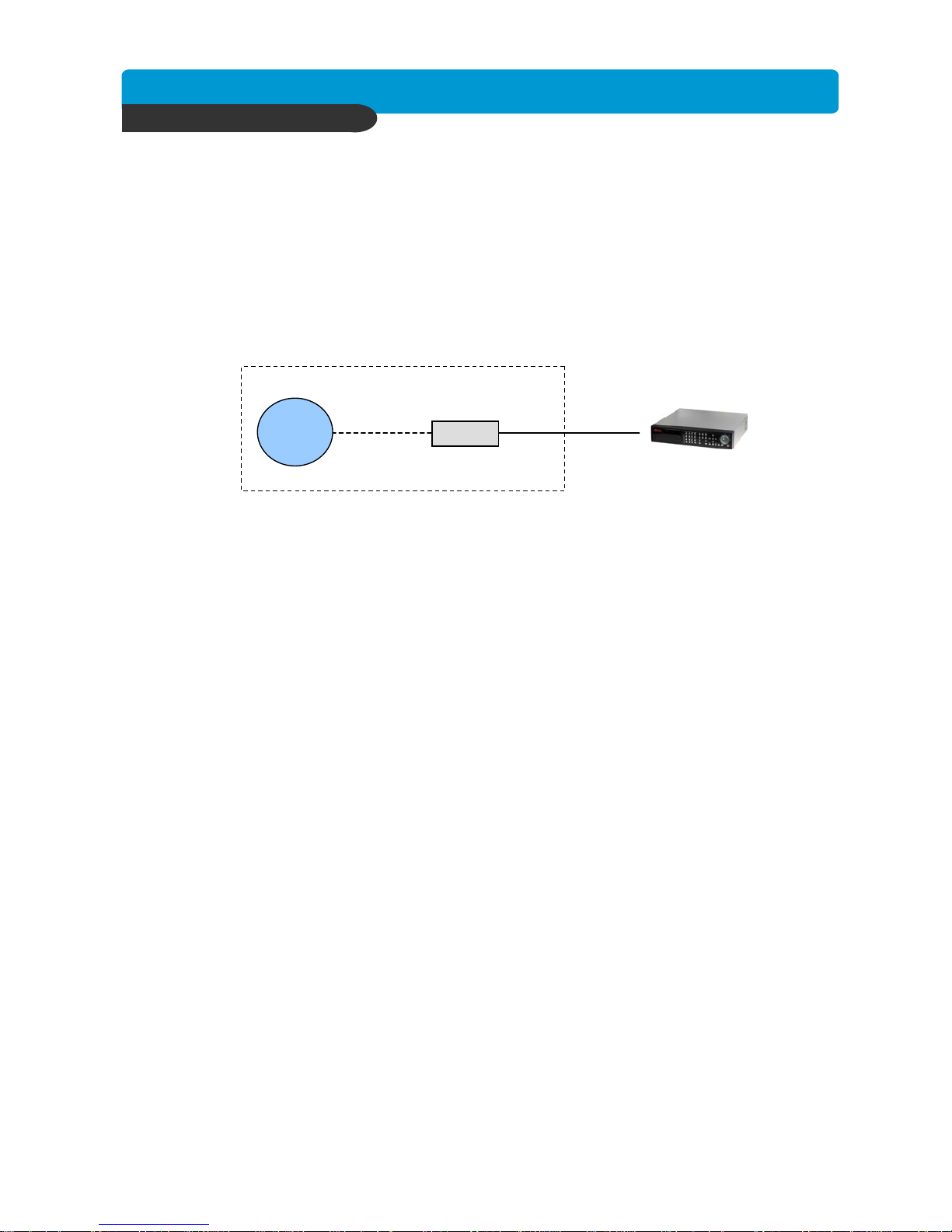
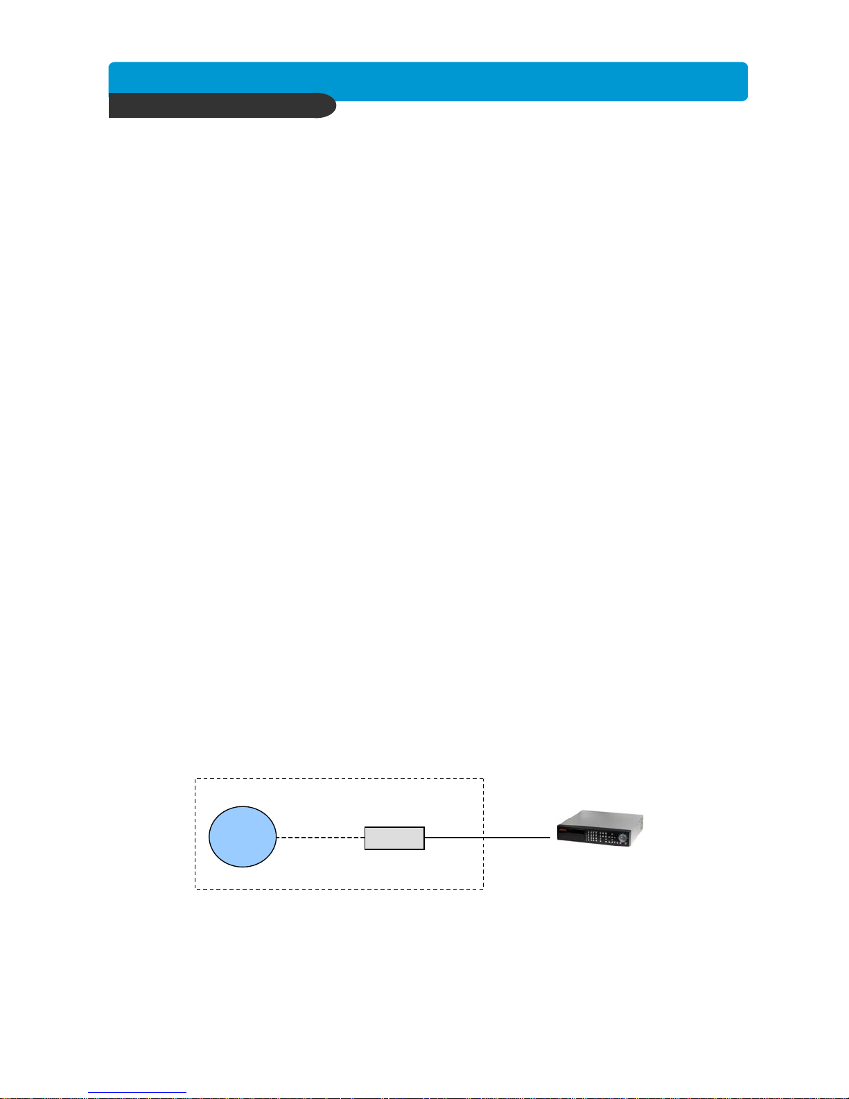
Case B : Single Static IP Directly Connected to the DVR
Accessing the DVR using the Remote Software for CASE A
Configure the DVR as follows :
1. Set the DVR to MANUAL for the TCP/IP settings. Do not use DHCP SETUP for this
application or verify that DHCP SETUP is set to MANUAL.
2. IP ADDRESS : assign it a public IP address(ex : 24.106.1.195)
a. You need to assign the DVR an IP address just as you would a PC.
b. The static IP address that you received from your Internet provider is the address
that you will assign this DVR, if you do not know this IP address please contact your
provider.
c. When configuring the DVR’s IP address information, the version of firmware within
the units may display the IP addresses differently. For simplicity sake,
24.106.1.195 may have to be configured as 24.106.001.195
3. PORT NUMBER : 8000
a. 4 channel, 8 channel & 16 channel : This number is stated explicitly.
b. For most situations, please use the default 8000 for simplicity.
4. SUBNET MASK : 255.255.255.240 (example)
a. Along with your static IP address you should have received your subnet mask from
your Internet provider. Please use that subnet mask when configuring the DVR. If
you did not receive this information contact your service provider.
5. GATEWAY : 24.106.1.193(example)
a. Along with your static IP address you should have received your gateway or default
gateway from your Internet provider. Please use that gateway when configuring the
DVR. If you did not receive this information contact your service provider.
6. Please DO NOT configure MAC ADDRESS or DHCP SETUP.
7. Your DVR is now ready for access.
LOCALLY :
You cannot physically access the unit locally since a router was not used in this case.
Internet
(ISP)
Modem
DVR
Phone line
Or CATV
Page 35
Best picture quality DVR
JPEG2000 Stand-alone DVR
34
CHAP. 6 Network Setup
REMOTELY :
To access the DVR remotely, open the remote viewing software and click on the “Settings”
button. As far as TCP/IP connectivity is concerned only 4 entries need to be made :
For CASE A, you have received a static IP from your Internet provider. That static IP
address is what you must enter into the software for connectivity to take place(this should be
the same IP address configured in the DVR). Contact your provider if you have misplaced
the forms stating your static IP address. As in the above example I would input the :
1. Public IP address of 24.106.1.195
2. Port : 8000(this has to match what is configured in the DVR)
3. User ID : (always leave the default “ admin “)
4. Password : this must match what is configured in the DVR
a) 4,8,16 channel default : null(NO PASSWORD)
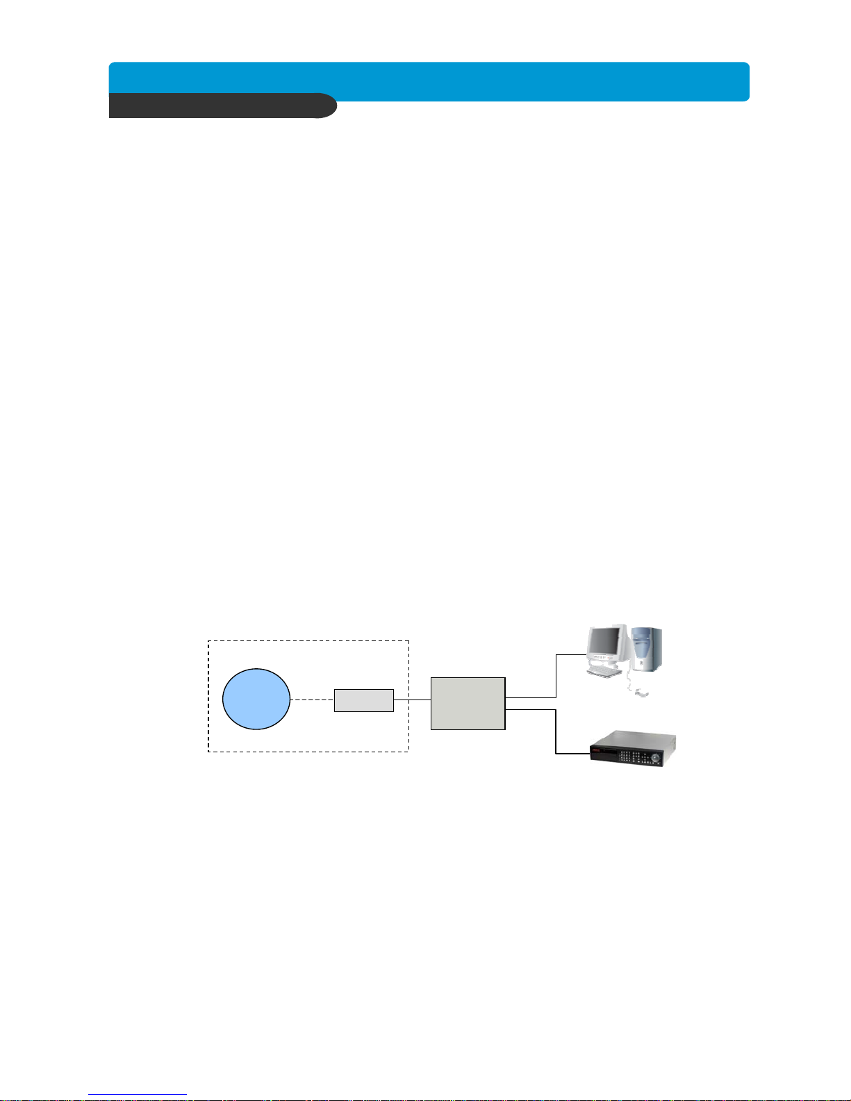
Case C : Dynamic or PPPoE IP w/Personal Router
Configure the DVR as follows :
1. Set the DVR to MANUAL for the TCP/IP settings. Do not use DHCP SETUP for this
application or verify that DHCP SETUP is set to MANUAL.
2. IP ADDRESS : assign it a private IP address(ex : 192.168.0.105)
a. You need to assign the DVR an IP address just as you would a PC.
b. The IP address you assign must be unique to your local network as well as “match”
your local network. For information on how to choose a unique IP that matches your
network, consult the FAQ.
c. The IP address you assign must be a private IP address. For information on what a
private IP address is, consult the FAQ.
d. When configuring the DVR’s IP address information, the version of firmware within
the units may display the IP addresses differently. For simplicity sake,
192.168.1.105 may have to be configured as 192.168.001.105
3. PORT NUMBER : 8000
a. 4 channel, 8 channel & 16 channel : This number is stated explicitly.
b. For most situations, please use the default 8000 for simplicity.
4. SUBNET MASK : 255.255.255.0 (example)
a. Assign the DVR the same exact subnet mask as your PC.
5. GATEWAY : 192.168.0.1(example)
a. Assign the DVR the same exact gateway(or default gateway) as your PC.
6. Please DO NOT configure MAC ADDRESS or DHCP SETUP.
7. You will need to forward port 8000 through your router. Please forward port 8000 to the
IP ADDRESS you have assigned the DVR.
8. Your DVR is now ready for access.
* For detail information on the above, please consult the FAQ.
PC
DVR
Internet
(ISP)
modem
Personal
Router
w/switch
Phone line
Or CATV
Page 36
Best picture quality DVR
JPEG2000 Stand-alone DVR
35
CHAP. 6 Network Setup
REMOTELY :
To access the DVR remotely, that is from outside your local network, follow the above
directions for accessing locally, except for the IP address. For CASE C, you have received a
dynamic or PPPoE IP from your Internet provider. That static IP address is what you must
enter into the software for connectivity to take place(NOT the IP of the DVR). You may be
able to contact your provider to determine your current IP address. You can also try
accessing your router and locating the status page that should list the WAN or Internet IP
address. Since you are accessing the DVR via a router, you must enter the router’s WAN IP
address which is the exactly the same as the IP that you have dynamically received from
your Internet provider. Take into consideration that this scenario is not recommended, due to
the nature of dynamic addressing. Dynamic address may change randomly or on power
failures. If you are unable to connect suddenly, first verify that your dynamic IP address has
not changed.
Accessing the DVR using the Remote Software for CASE C
LOCALLY :
To access the DVR locally, that is from your local network on site from where the DVR
is installed. Open the remote viewing software and click on the “Settings” button.
As far as TCP/IP connectivity is concerned only 4 entries need to be made :
1. IP address : Input the IP address that you assigned the DVR. As in the above example
I would input the private IP address of 192.168.0.105
2. Port : 8000(this has to match what is configured in the router and in the DVR)
3. User ID : (always leave the default “ admin “)
4. Password : this must match what is configured in the DVR
a) 4,8,16 channel default : null(NO PASSWORD)
Case D : Multiple Static IPs w/Personal Router
Configure the DVR as follows :
1. Set the DVR to MANUAL for the TCP/IP settings. Do not use DHCP SETUP for this
application or verify that DHCP SETUP is set to MANUAL.
2. IP ADDRESS : assign it a public IP address(ex : 24.106.1.195)
a. You need to assign the DVR an IP address just as you would a PC.
b. For this case you must have received several available static IP addresses. Of those,
choose one that is not in use to which you can assign the DVR, if you do not know your
available IP addresses please contact your provider.
c. When configuring the DVR’s IP address information, the version of firmware within
the units may display the IP addresses differently. For simplicity sake,
24.106.1.195 may have to be configured as 24.106.001.195
3. PORT NUMBER : 8000
a. 4 channel, 8 channel & 16 channel : This number is stated explicitly.
b. For most situations, please use the default 8000 for simplicity.
Internet
(ISP)
modem
Personal
Router
w/switch
PC
DVR
Phone line
Or CATV
Page 37
Best picture quality DVR
JPEG2000 Stand-alone DVR
36
CHAP. 6 Network Setup
4. SUBNET MASK : 255.255.255.240 (example)
a. Along with your static IP addresses you should have received your subnet mask
from your Internet provider. Please use that subnet mask when configuring the DVR.
If you did not receive this information contact your service provider.
5. GATEWAY : 24.106.1.193(example)
a. Along with your static IP addresses you should have received your gateway or
default gateway from your Internet provider. Please use that gateway when
configuring the DVR. If you did not receive this information contact your service
provider.
6. Please DO NOT configure MAC ADDRESS or DHCP SETUP.
7. Your DVR is now ready for access.
LOCALLY :
To access the DVR locally, open the remote viewing software and click on the “Settings”
button. As far as TCP/IP connectivity is concerned only 4 entries need to be made.
For CASE D, you have received a static IP from your Internet provider. That static IP
address is what you must enter into the software for connectivity to take place(this should be
the same IP address configured in the DVR). Contact your provider if you have misplaced
the forms stating your static IP address. As in the above example I would input the :
1. Public IP address of 24.106.1.195
2. Port : 8000(this has to match what is configured in the DVR)
3. User ID : (always leave the default “ admin “)
4. Password : this must match what is configured in the DVR
a) 4,8,16 channel default : null(NO PASSWORD)
Accessing the DVR using the Remote Software for CASE D
REMOTELY :
To access the DVR remotely, just follow the same instructions for local access.
Case E : Dynamic IP Directly Connect to the DVR with High Speed Cable
Internet
(ISP)
Modem
DVR
CATV
Page 38

Best picture quality DVR
JPEG2000 Stand-alone DVR
37
CHAP. 6 Network Setup
Configure the DVR as follows :
For this application you can still use the DVR for remote access, yet you will have to
verify the IP address within the DVR on a continuous basis to ensure the IP address
hasn’t changed. This setup will not work with most Dynamic DSLDKDKD providers.
In any instance in which the DVR cannot detect an IP, please use CASE C.
1. Unplug the power from the modem.
2. Turn off the DVR.
3. After waiting 5 minutes, power on the modem followed by the DVR.
4. Enter the TCP/IP Setup menu.
5. Enter DHCP Setup.
6. Select IP DETECT MODE.
7. Press ENTER.
8. It should now display DHCP.
9. Cursor down to REQUEST IP and hit ENTER.
10. The Unit will now send a request to a DHCP server asking for IP address information.
a. If it is unable to detect an IP address, contact your ISP to reset the modem, before
trying again.
b. After an IP has been received, the lease time listed under IP LEASE TIME is just
notifying you when the DVR will try to renew the IP address. Typically it will try to
receive the same IP, but it is a good idea to check your IP on a continuous basis.
11. Exit DHCP SETUP.
12. Select IP ADDRESS to determine the IP address the unit has received.
13. The DVR is now ready for access.
REMOTELY :
To access the DVR remotely, open the remote viewing software and click on the “Settings”
button. As far as TCP/IP connectivity is concerned only 4 entries need to be made.
For CASE E, you have received a dynamic IP from your Internet provider. That dynamic IP
address is what you must enter into the software for connectivity to take place(this should be
the same IP address configured in the DVR). Check your DVR’s current IP address for
access :
1. IP address : 24.106.1.195(example)
2. Port : 8000(this has to match what is configured in the DVR)
3. User ID : (always leave the default “ admin “)
4. Password : this must match what is configured in the DVR
a) 4,8,16 channel default : null(NO PASSWORD)
Accessing the DVR using the Remote Software for CASE E
LOCALLY :
You cannot physically access the unit locally since a router was not used in this case.
Page 39
Best picture quality DVR
JPEG2000 Stand-alone DVR
38
CHAP. 6 Network Setup
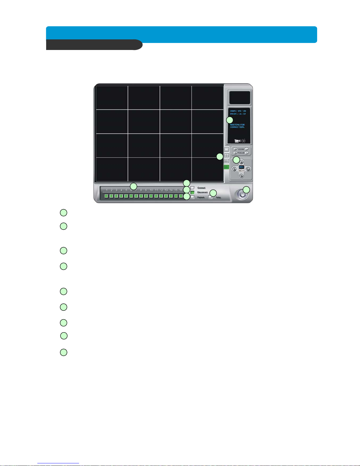
6-2. Remote Viewer program
- Power switch : Press the Power switch to exit the program. Please disconnect the live feed before
powering off the software
- Connect button : Press the Connect button to view the live images from the DVR. These are the same
images being displayed on the monitor of the DVR, with a delay depending on your
internet connection at both the DVR location and from where you’re currently accessing.
- Disconnect button : Press this button to disconnect from the DVR unit. Then you may power off the
software.
- Screen Division button : Select how many channels to view simultaneously(single,4-split,9-split,
or 16 split). When you select a view you will see the Channel Numbers highlighted
which determine what channels are currently being viewed.
- Channel number button : Select the channel that you want to view based on what Screen Division
view is enabled.
-Statuswindow : Display’s the current time and date based. The date is in the format : Year/Month/Day.
You will also see the status of your connection.
- Setup : Enables the software configuration screen.
-Playback : Enables the remote playback screen.
- PTZ control : You can control a PTZ camera via the software with these controls.
a. First, you must input or configure the specific PTZ protocol into the software in
order to communicate with the PTZ device.
b. When you press any of the controls for the PTZ, please press and hold the button
for 1-2 seconds per instance to compensate for the data transmission rate. If you
do not and instead simply click the PTZ buttons, you may get undesired results
(having the requested operation transmitted repeatedly, regardless of your intention).
c. The plus and minus buttons send the PTZ commands to the corresponding PTZ
camera ID.
1
2
3
4
5
6
7
1
2
3
4
5
6
7
8
8
9
9
Page 40
Best picture quality DVR
JPEG2000 Stand-alone DVR
39
CHAP. 6 Network Setup
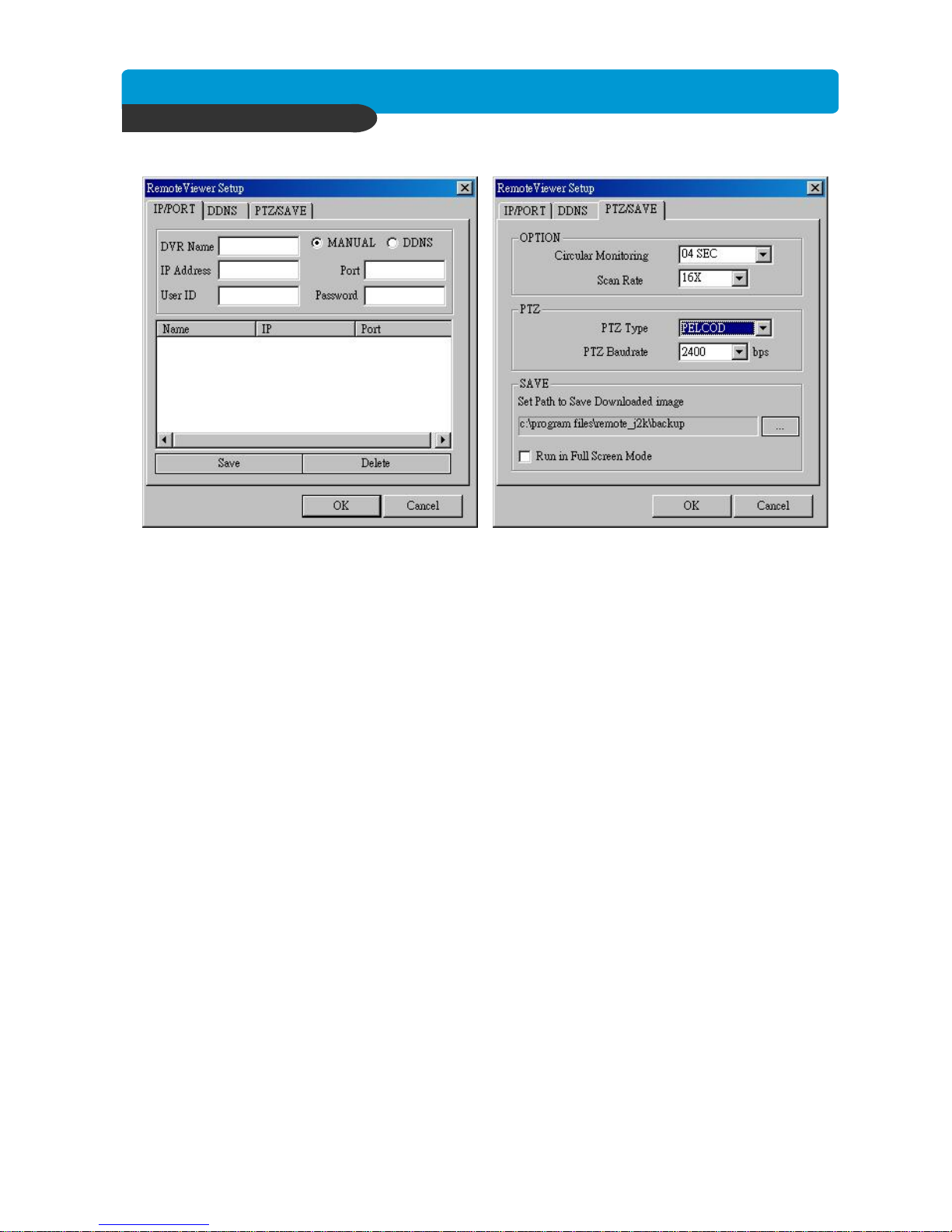
Setting Screen
Name: This just identifies your settings. The settings are automatically saved under this label
when you hit ‘OK’.
IP Address : Based on your network scenario and from where you’re accessing, enter the appropriate
IP address.
PORT : Enter the Port Number you assigned the DVR.
USER ID : Always enter ‘admin’
Password : This must match the password on the DVR. For simplicity, just use numbers.
Circular Monitoring Interval : This determines the speed at which the channels sequence, when the
SEQUENCE button is used from the main interface.
PTZ TYPE : If using PTZ device or camera, select the protocol your PTZ camera is using from the list of
preconfigured protocols.
PTZ Baudrate : Setup PTZ camera buad rate.
Set Path to Save Recorded Images : Determines the location and folder on your PC where the saved
video clips are stored. If you do not specify a valid location, then the
program will save all files in the default location of
C:\Program Files\Remote_J2K
Run in full screen mode : When checked, this will enable the program to re-adjust the interface to
completely fill your computer screen.
Page 41
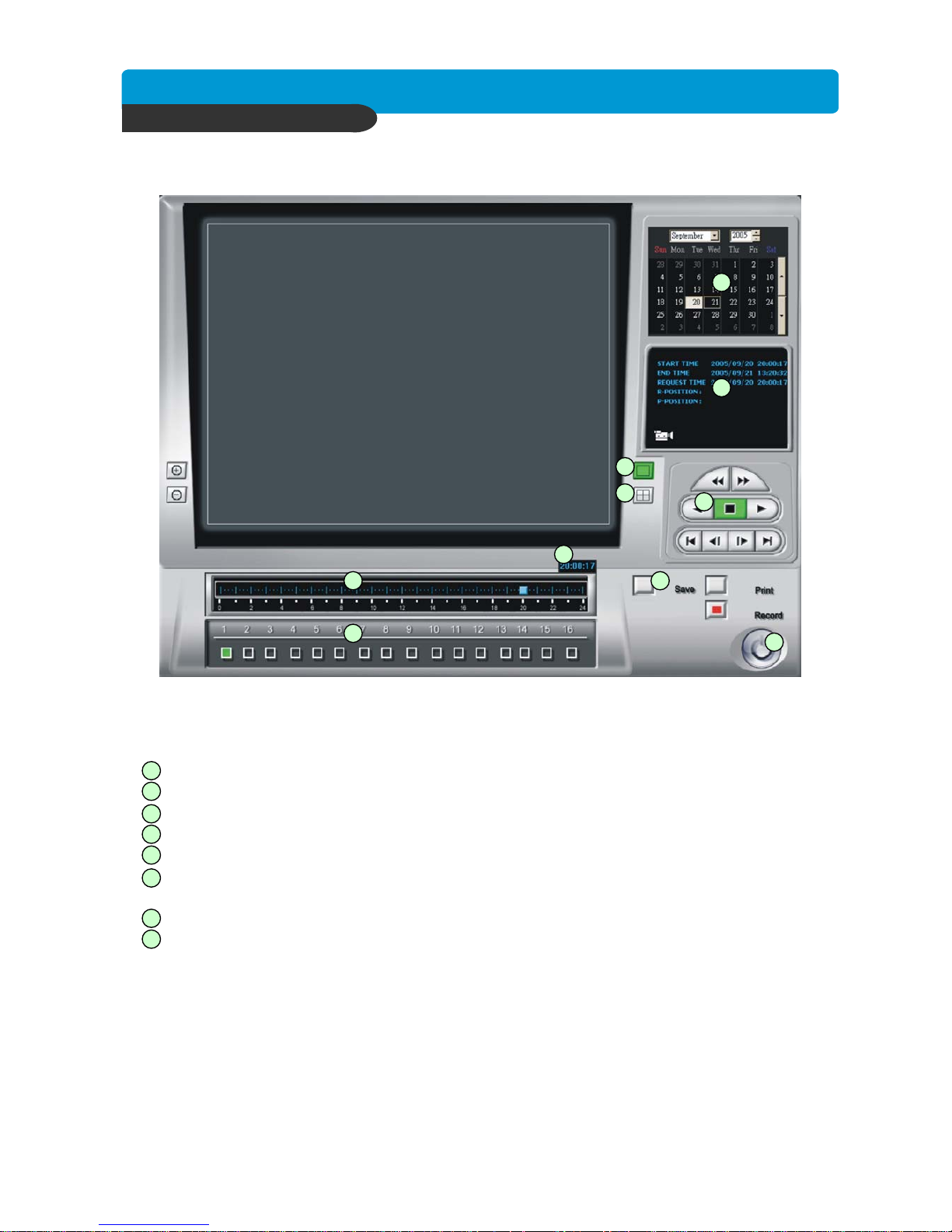
Best picture quality DVR
JPEG2000 Stand-alone DVR
40
CHAP. 6 Network Setup
PLAYBACK INTERFACE
Function of each button in Search window.
Exit : Exit to live window.
Full screen : Select a certain camera to view in full screen.
Quad : To view quad mode (4 channels at the same time)
Time : The recording time & date information of the pictures which is being played.
Channel selection : Select each camera.
Time selection : Select a time from which user want to see. The playback will be started from this
point.(drag the point using mouse)
Start and end time : Indicate record starting time and end time of images on HDD
Other operating button : Refer to the next page description.
1
2
3
4
5
6
7
8
1
2
3
4
5
6
7
8
9
10
Page 42
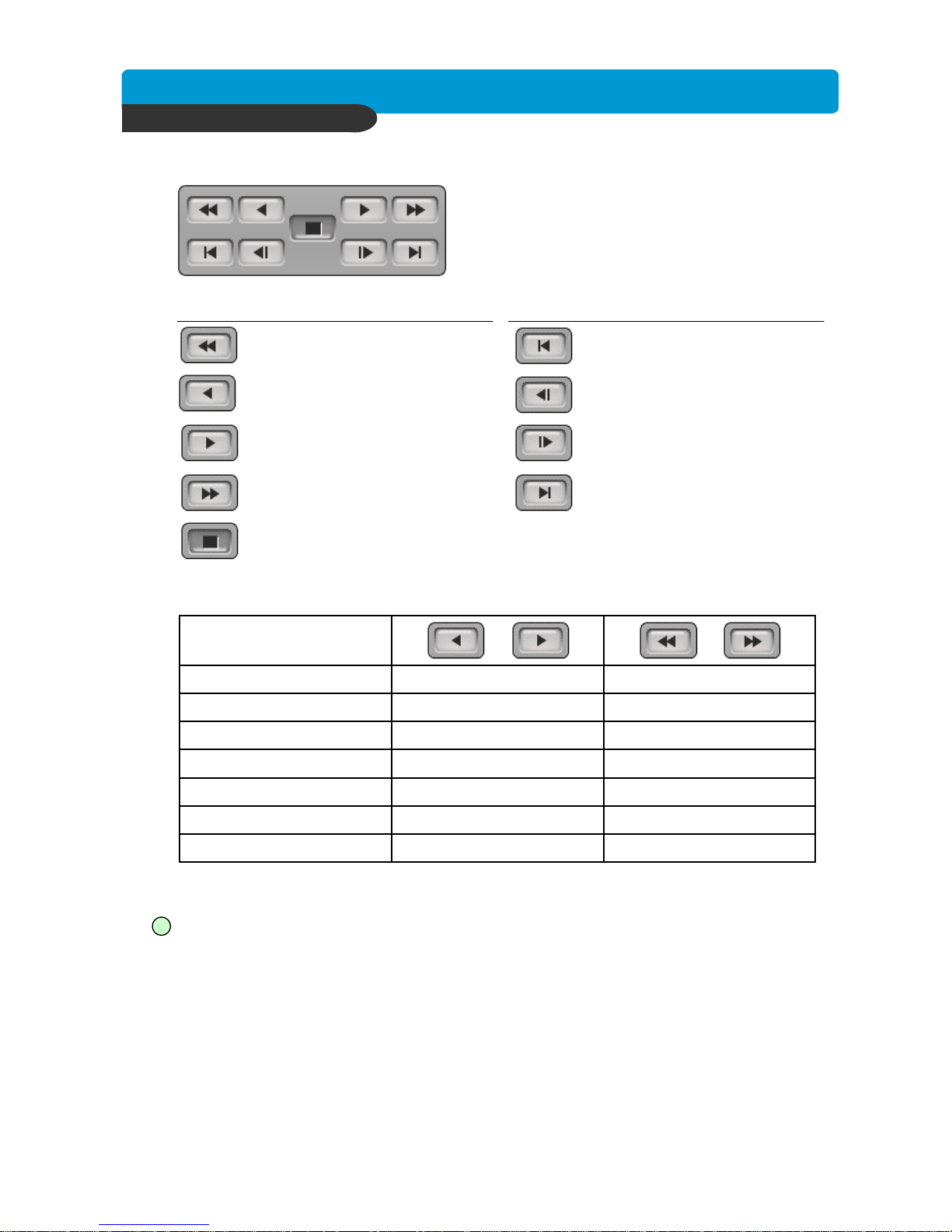
Best picture quality DVR
JPEG2000 Stand-alone DVR
41
: Play Fast backward
: Move to the start of recording
: Play backward(1X)
: Move to the previous hour
: Play Forward(1X)
: Move to the previous hour
: Play Fast Forward
: Move to the end of recording
: Stop playback
* Speed of playback according to scan rate
60x1x64x
30x1x32x
16x1x16x
8x1x8x
4x1x4x
2x1x2x
1x1x1x
Scan rate
or or
Maximum playback speed of DVR is 60x.
9
: Command button.
a) Save : After pressing the Stop button, you can save the currently viewed channels as an
image(jpg)
b) Print : After pressing the Stop button, you can print the currently viewed channels.
c) EVENT : Not available.
d) RECORD : Press this button to record the currently viewed channels to the specified location in
the Settings screen. Press the button again to stop recording and allow the video
capture to be saved before any other action.
CHAP. 6 Network Setup
Page 43

Best picture quality DVR
JPEG2000 Stand-alone DVR
42
10
: Calendar
Use this to select the date you wish to playback. The filled in square outlines the date that is at the
beginning of the hard drives. The outlined square indicates the data at the end of the hard drives.
Select the date you wish to view. Verify a filled in square for that particular date. If an invalid date is
selected it will default to the beginning of the hard drive(s).
Notice : To see continuous live view, it is recommended to set recording mode of DVR unit
in continuous recording mode. If it is set at motion recording mode, image transmission
is done only when motion is detected, and user only see still images for most of cases.
Notice : While user access to DVR unit via IP network to see live view, the DVR unit continues to record.
While user see recorded images, DVR unit shows live images through monitor connected
to DVR unit, but recording is stopped, if MULTIPLEX mode in the SETUP menu in DVR is
set at SIMPLEX.
CHAP. 6 Network Setup
Page 44
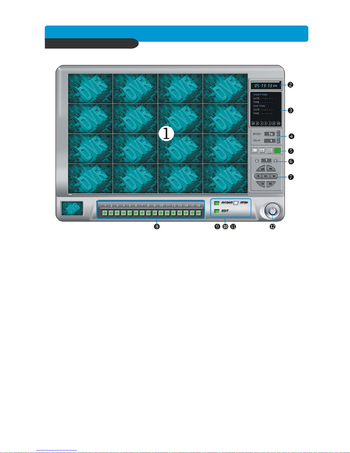
Best picture quality DVR
JPEG2000 Stand-alone DVR
43
CHAP. 6 Network Setup
6-3. Back-up CD Player
DVR units are with a built-in CD-RW, and user can copy images to CD.Using back-up CD player, user
can see images on back-up CD, and function of each button inBack-up CD player is as below.
1. Display screen : To display the backup image
2. Time : Current time.
3. Status Window : Start & End of time & date, Status of operating button.
When user play forward/backward, recorded time will appear.
4. Play Speed button : User can adjust play speed by pressing up/down button.
(2X,4X,8X,16X,32X,64X) Delay : (1, 1/2, 1/4, 1/8, 1/16)
5. Screen division : Select Full / 4 / 9 / 16 split screen.
6. Page button : This button is just working when screen-division is 4-split in 8 ch DVR, or 4-split or
8-split in 16 ch DVR. Moves to next page.
7. Operation button : User can search recorded data using these buttons.
a) Move the slide bar to start position
b) Play fast backward in preset speed
c) Play backward at 1x speed
d) Pause
e) Play forward at 1x speed
f ) Play fast forward in preset speed
g) Move the slide bar to end position
8. Channel button : Select channel to see pictures in full screen.
9~11. Function button
a) OPEN : Open the Back-up CD Player.
b) EDIT : User can save and print recorded image on Edit mode. This edit button will work when you
selected full screen .
c) AVI SAVE : To save the backup image as AVI format .
12. EXIT : Exit from Back-up CD Player.
Page 45
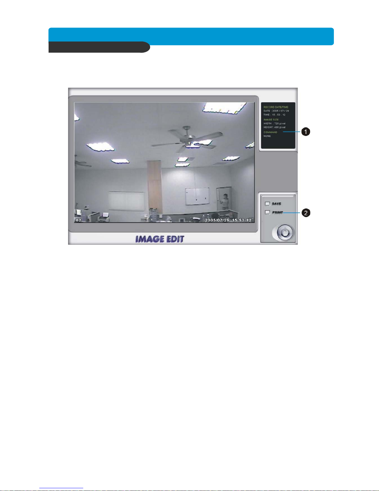
Best picture quality DVR
JPEG2000 Stand-alone DVR
44
Image EDIT
1. Image edit status window : Shows record time & date, Image size, Command status.
2. Function button
a) Save : User can save an image in JPEG format. It is saved in the folder where you installed
back-up CD player.
b) Print : User can print current image user selected
c) EXIT : Return to Back-up CD Player mode.
CHAP. 6 Network Setup
Page 46
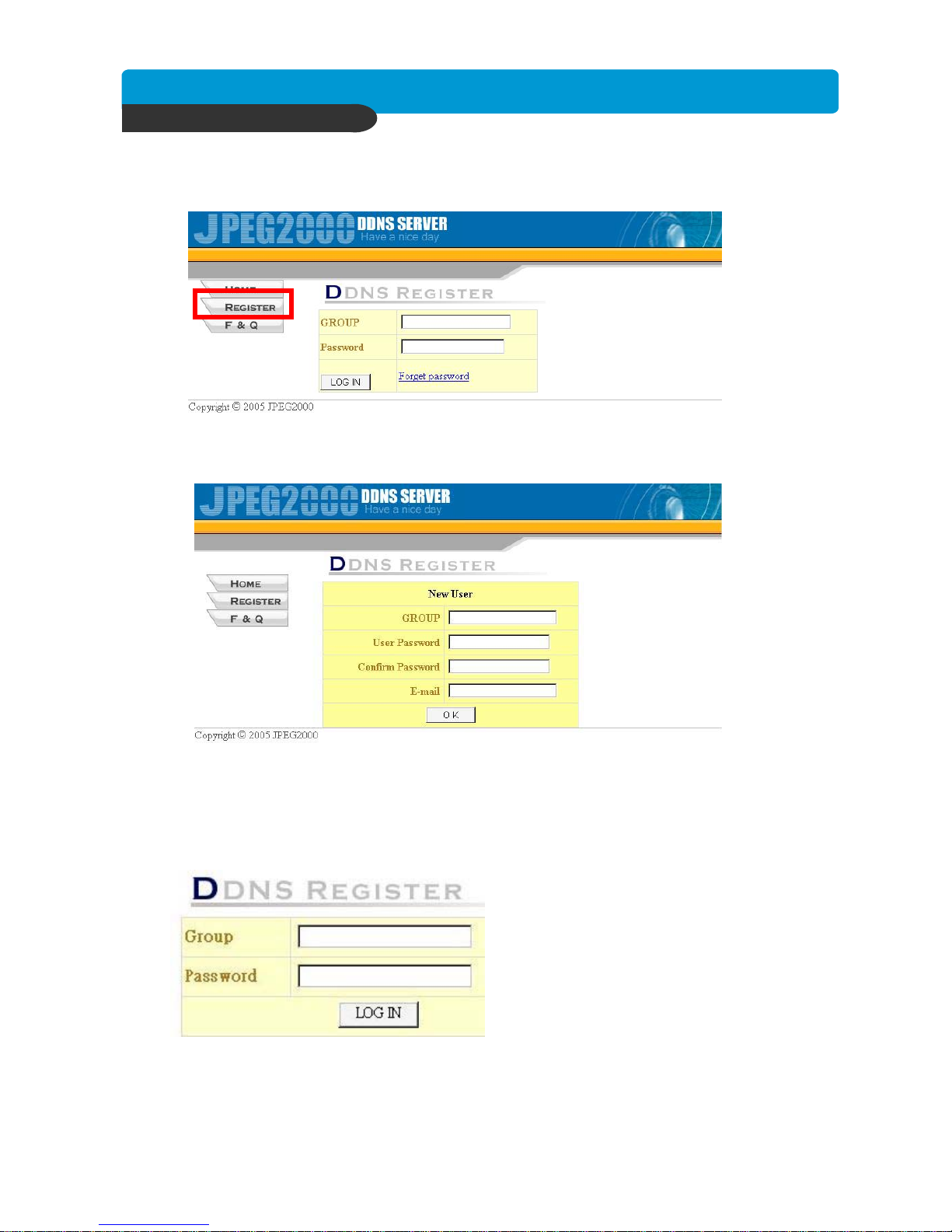
Best picture quality DVR
JPEG2000 Stand-alone DVR
45
CHAP. 6 Network Setup
6-4. DDNS function
1)DDNS SERVER SETUP
1. Use IE Browser connected to DDNS SERVER(http:// 59.124.143.151)
Select [REGISTER] to register a new user.
2. Add User ID
Group: Input User ID
User Password: Input Password
Confirm Password: Input Password again
E-mail: Add an Email address for reminding password
3. Input Group and password, then click ”LOG IN”
Page 47
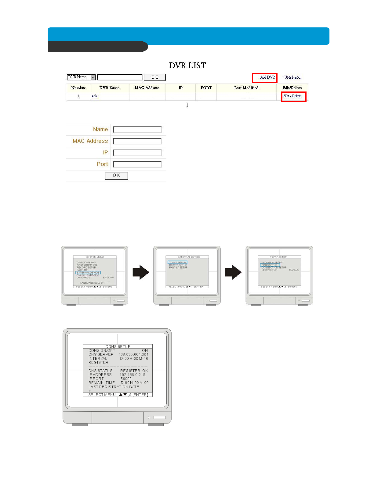
Best picture quality DVR
JPEG2000 Stand-alone DVR
46
CHAP. 6 Network Setup
4. Select “ADD DVR” to add DVR information.
5.Key in DVR information.
•Name: set DVR name.
•MAC ADDRESS: set DVR MAC address. You can find
MAC address in DVR menu.
•IP:Input DVR’s IP address
•Port:Input DVR’sport.
(Name and MAC Address must fill out. IP and Port can
leave for blank).
6.Edit and Delete DVR data.
EDIT: Modify the DVR database.
DELETE: Delete the DVR database.
2)DVR SETUP
1. In DVR menu f [EXTERNAL DEVICE]f[TCP/IP SETUP] f[DDNS SETUP]
2. DDNS setup
DDNS ON/OFF: Open or Close DDNS function.
DNS SERVER: Show DNS server.
INTERVAL: Auto update DVR’s IP and Port to DDNS
server (D-every day / H-every hour / M-every minute)
REGISTER: Connect to DDNS server and input DVR
database to DDNS server.
DNS STATUS: Show DDNS server status.
IP ADDRESS: Show the IP address which register in
DDNS server.
IP PORT: Show the Port which register in DDNS server.
REMAIN TIME: To indicate the rest time of showing
the next update time of IP address.
LAST REGISTRATION DATE: Show the latest
registration date.
Page 48
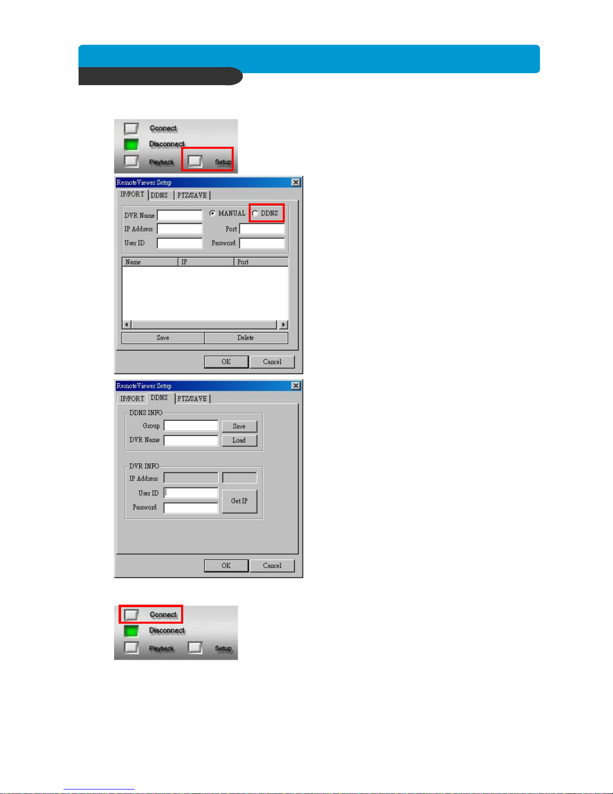
Best picture quality DVR
JPEG2000 Stand-alone DVR
47
CHAP. 6 Network Setup
3) Remote software setup
1.Click “Setup”.
2.Select “DDNS” page
3.setup DDNS database.
DDNS INFO
GROUP: Input ID (Register in DDNS web).
DVR NAME: Input DVR name.
DVR INFO
IP Address: Show IP address and Port from DNS
server.
User ID: Input DVR’s login ID.
Password: Input DVR’s login password.
Connect: Connect to DDNS server and get IP
Address of DVR server.
Input Group, Name, User ID, Password, then click
“Connect”. After getting DVR’s IP address and Port,
click “OK” to exit.
4.Click “CONNECT” to connect to DVR.
Page 49
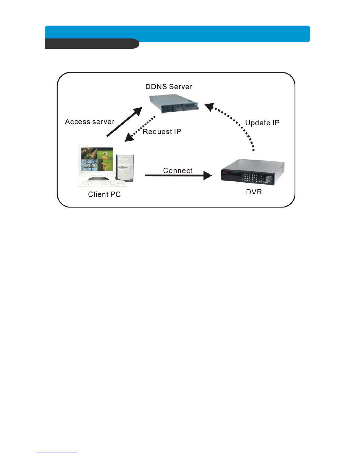
Best picture quality DVR
JPEG2000 Stand-alone DVR
48
CHAP. 6 Network Setup
4) DDNS Map
1.DVR connect to DDNS server automatically and update the IP address by itself
2. It will access server and request IP address from DDNS server before network connection
3. DDNS server will give an updated IP address
4. Client PC will connect to DVR by the updated IP address.
[
XY
Z
Page 50
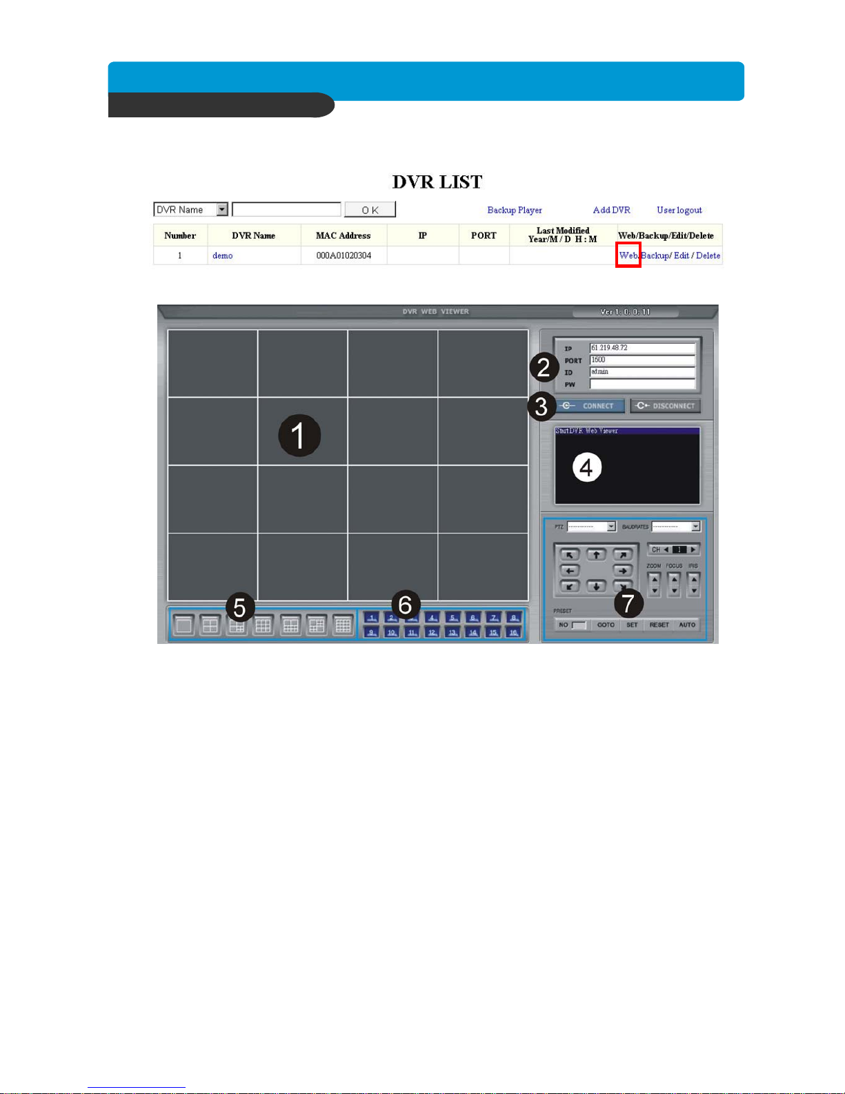
Best picture quality DVR
JPEG2000 Stand-alone DVR
49
5) IE Browser
z Click “WEB” to open IE browser
1.[Live picture]
z Shows the live pictures of DVR
2.[DVR info]
z IP: Indicate the IP address of DVR
PORT: Indicate the PORT of DVR
ID: Use ADMIN
PW: Enter the ADMIN’s password
3.[CONNECT/DISCONNECT]
z CONNECT: Connect to DVR and get the live picture
z DISCONNECT: Interrupt the connection with DVR
4.[Status Window]
z Shows the current status of connection
5.[Selection of multi screen]
z Switch to the different modes of multi-screen shows on monitor
6.[Channel selection]
z Select the single channel under single channel monitoring
7.[PTZ control]
z Control PTZ camera
Page 51
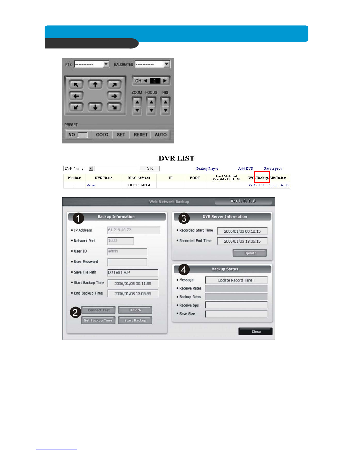
Best picture quality DVR
JPEG2000 Stand-alone DVR
50
PTZ: Select the protocol
BAUDRATE: Select the baud rate
CH: Select the ID of PEZ camera
ZOOM: Zoom in/out function of PTZ
camera
FOCUS: Focus function of PTZ camera
IRIS: IRIS function of PTZ camera
[PRESET]
GOTO: Active the preset function
SET: Set the preset location
RESET: Reset the preset location
AUTO: Auto Scan the PTZ camera
z Click “Backup” to open the web page “Web Network Backup”
6) Web Network Backup
1.Backup Information:
z IP Address: Enter the IP address of DVR
Network Port: Enter the port of DVR
User ID: Enter “Admin”
User Password: Enter Admin’s password
Save File Path: Indicate the path to save the backup file (This function is only active under
the connection is established”)
Start Backup Time: The start time of file backup (This function is only active under the
connection is established”)
End Backup Time: The end time of file backup (This function is only active under the
connection is established”)
Page 52
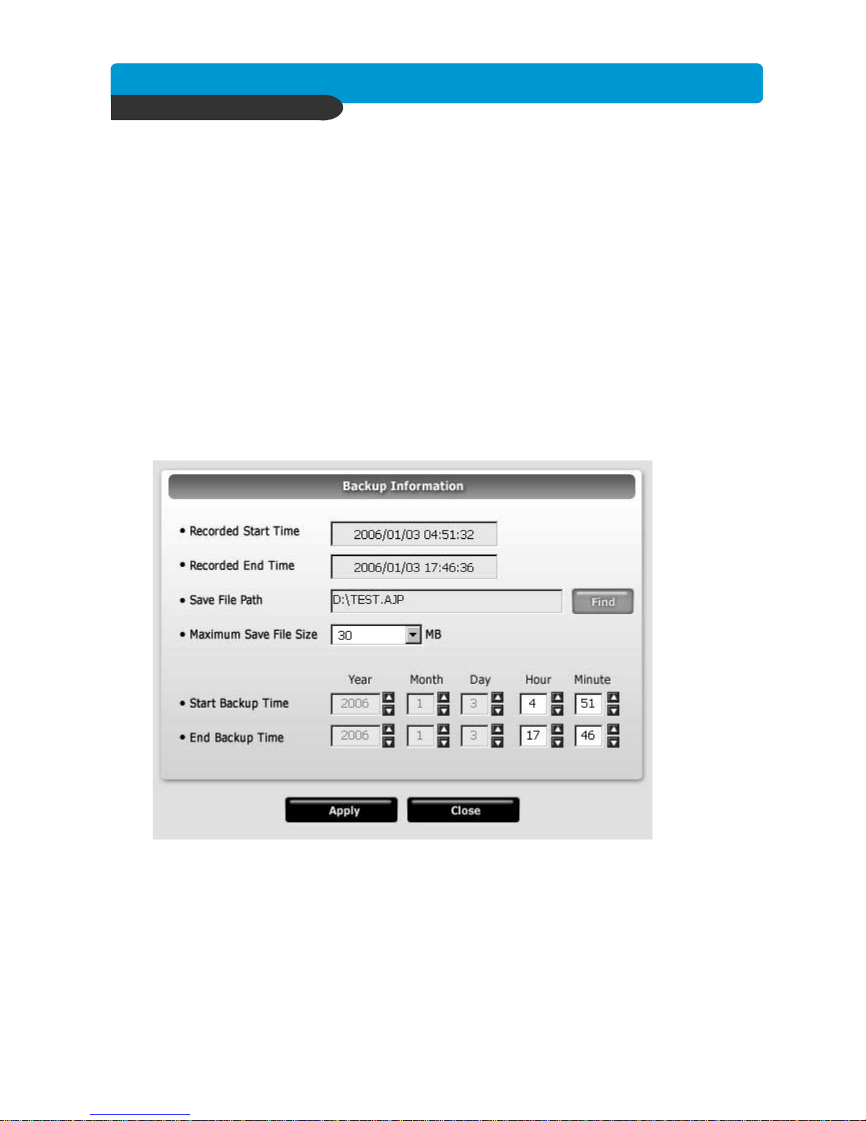
Best picture quality DVR
JPEG2000 Stand-alone DVR
51
2. Function setup :
z Connect Test : To test the status to DVR connection
Unlock: To get the record start/End time of DVR
Set Backup Time: Set the start/end time, size and path of file backup
Start Backup: Active the backup function
3. The information of DVR Server:
z Recorded Start Time: Indicate the recorded start time
Recorded End Time: Indicate the recorded end time
z Update: Update the recorded time
4. Backup Status
z Message: Indicate the backup status
Receive Rate: Indicate the percentage of backup image received
Backup Rate: Indicate the completed percentage of backup image received
Receive bps: Indicate the bps of backup image received
Save Size: Indicate the size of backup image saved
7) Backup Procedure
1. Select [Connect Test] to test the status to DVR connection
2. Select [Unlock] to get the record start/End time of DVR
3. Select [Set Backup Time] to setup the backup function
X
Indicate the recorded start/end time
Y
Click [Find] to set the path for saving the backup file
Z
Set the file size of backup file(30~700MB)
[
Set the start/end time of file backup
4. Click [Apply] to apply all setup
5. Select [Start Backup] to active the backup function (User can stop anytime during backup)
[
X
Y
Z
Page 53
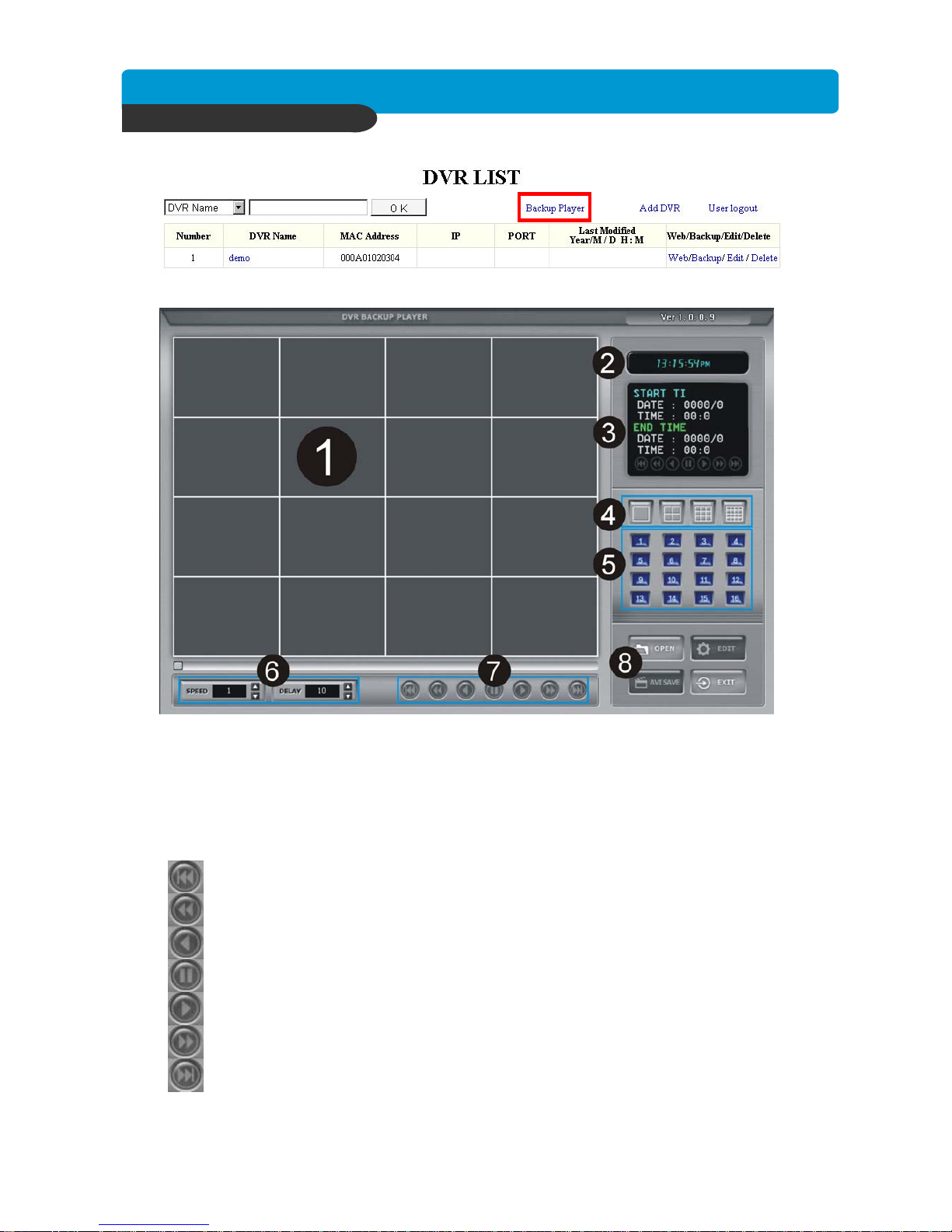
Best picture quality DVR
JPEG2000 Stand-alone DVR
52
8) Play backup file
z Click [Backup Player] to open the web page of “Backup Player”
1. Display the backup image
2. Indicate the present time of monitoring
3. Indicate the start/end time of backup file
4. Switch to the different modes of multi-screen
5. Channel selection: Ch1~Ch16
6. SPEED: Adjust the speed of fast forward DELAY: Adjust the speed of reward
7. Function bar on playback:
To the beginning
Fast Rewind
Rewind
Pause
Forward
Fast Forward
To the end
Page 54
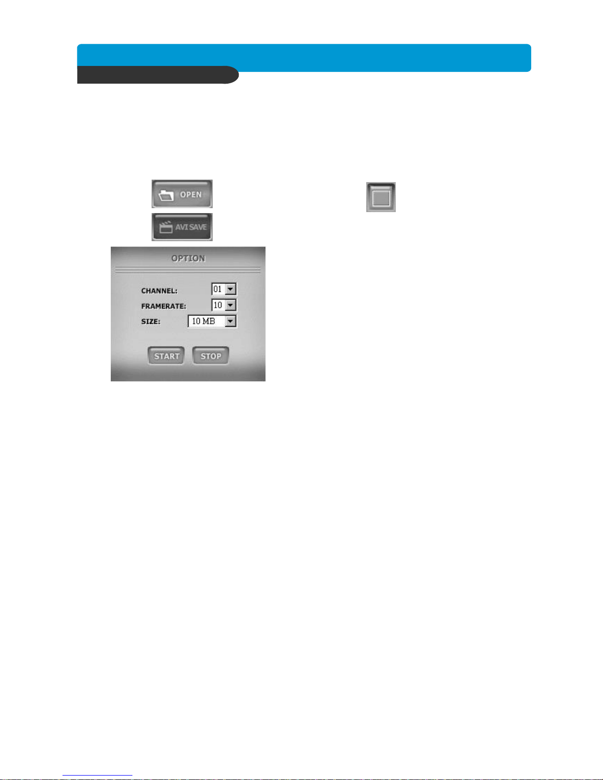
Best picture quality DVR
JPEG2000 Stand-alone DVR
53
8. Function keys: Indicate the present time of monitoring
z OPEN: Open the backup file
EDIT: Edit the backup image
AVI SAVE: To save the AVI file
EXIT: Log out the program
9) Save AVI file:
1. Click to open the backup file and select single channel
2. Click to open the AVI SAVE function
CHANNEL: Select a single channel
FRAMERATE : Set the frame rate
SIZE: Set the file size of AVI SAVE
START: Start AVI SAVE
STOP: Stop AVI SAVE
ÚThe AVI file path will be saved under C:\WEB_BACKUP
Page 55
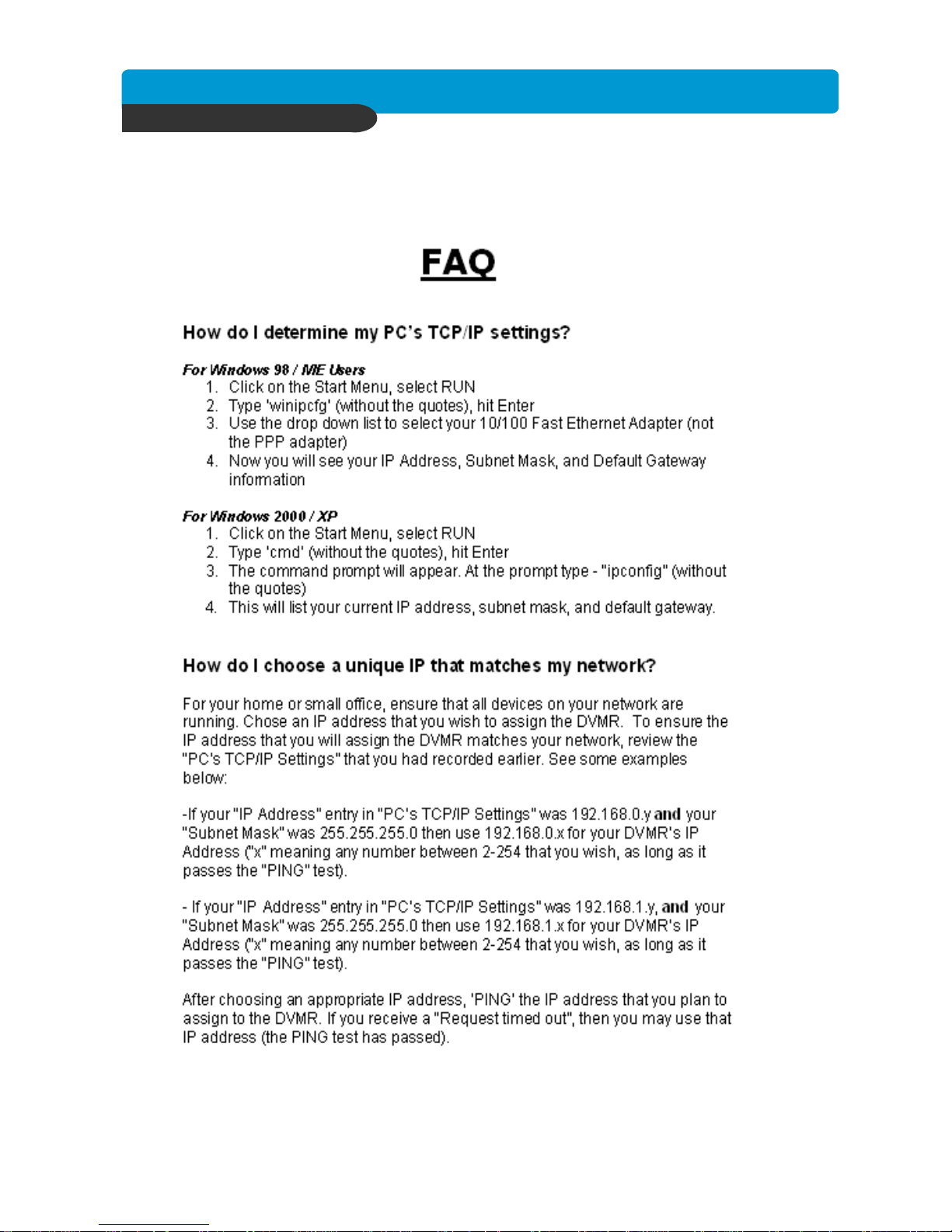
Best picture quality DVR
JPEG2000 Stand-alone DVR
54
6-5. Frequently Asked Questions
CHAP. 6 Network Setup
Page 56
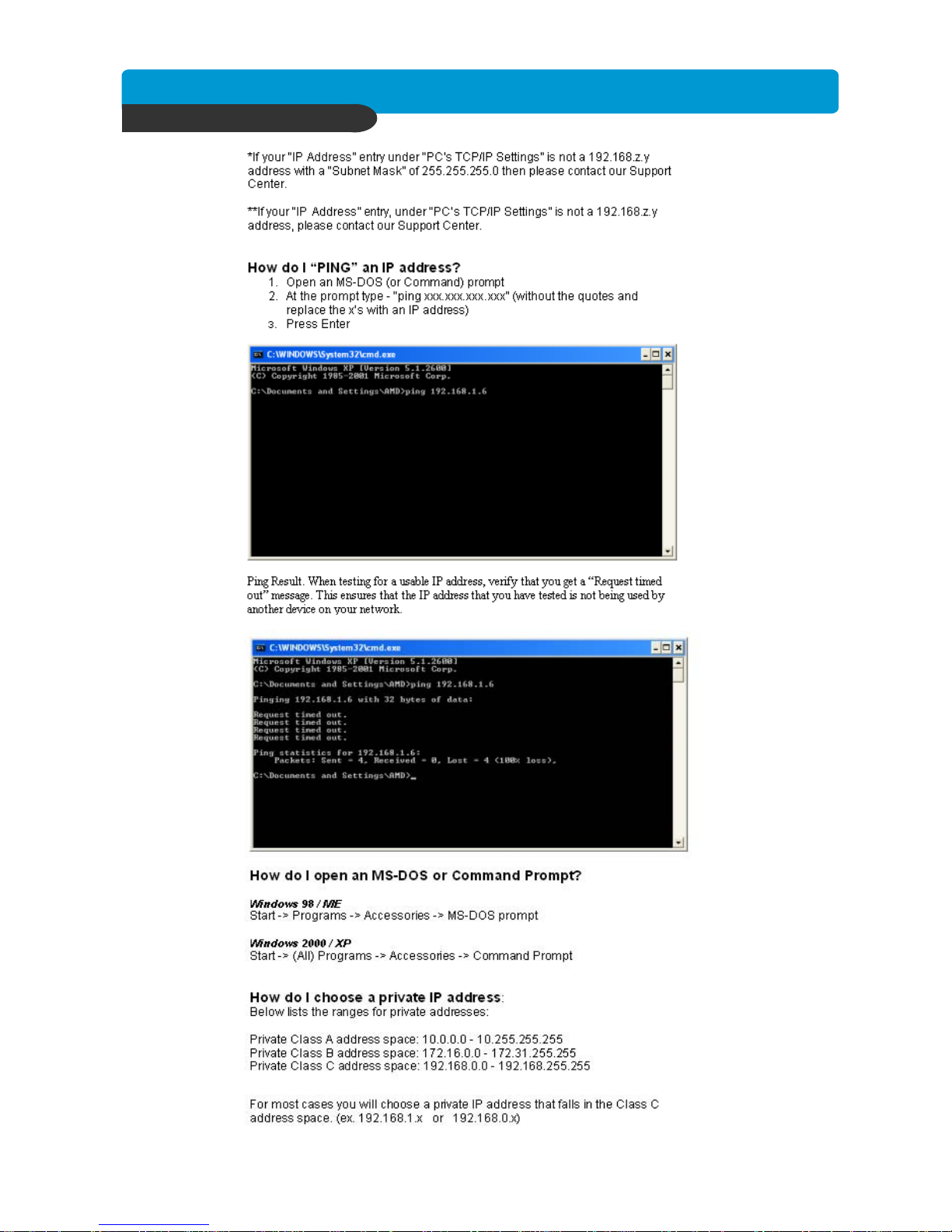
Best picture quality DVR
JPEG2000 Stand-alone DVR
55
CHAP. 6 Network Setup
Page 57
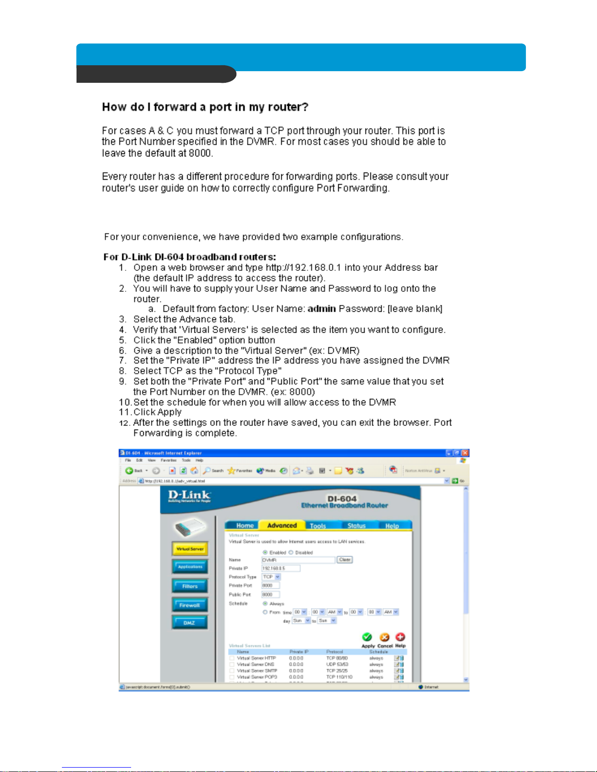
Best picture quality DVR
JPEG2000 Stand-alone DVR
56
CHAP. 6 Network Setup
Page 58
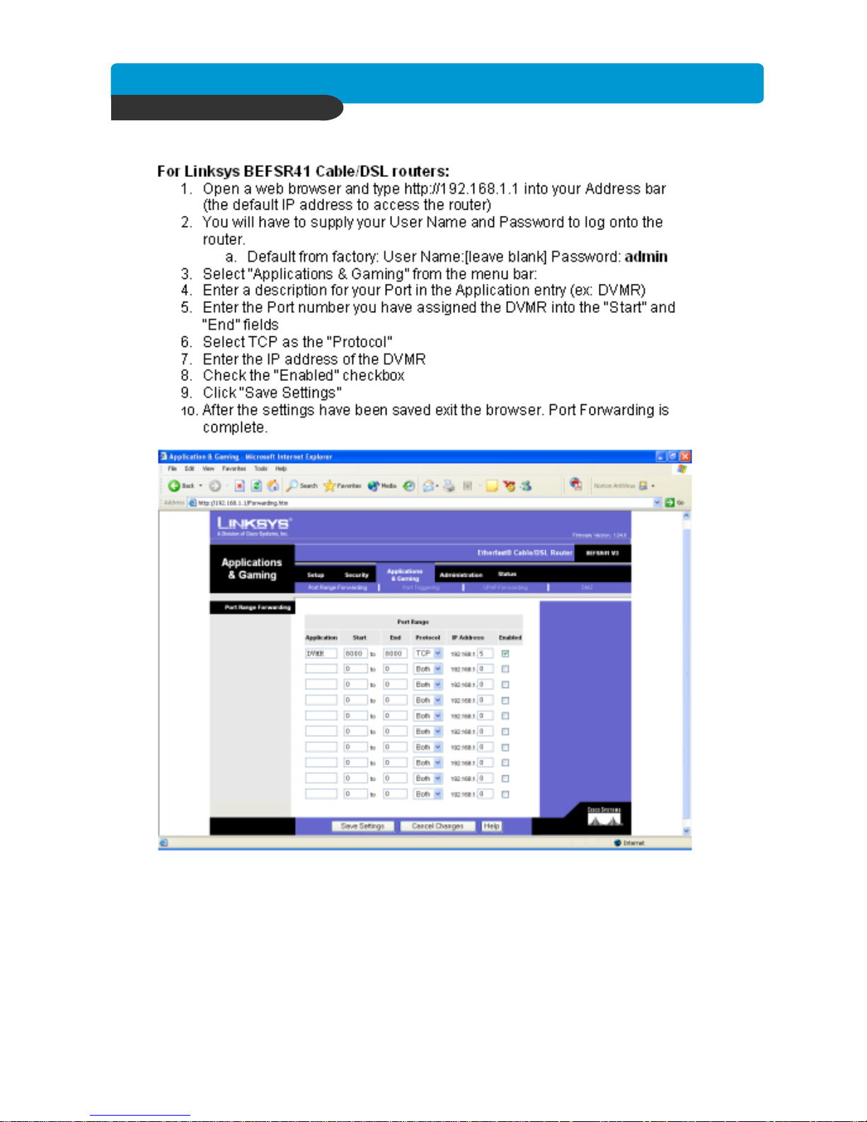
Best picture quality DVR
JPEG2000 Stand-alone DVR
57
CHAP. 6 Network Setup
Page 59

Best picture quality DVR
JPEG2000 Stand-alone DVR
58
Can I configure my DVMR for remote access using a Dial-Up connection?
Yes, it is possible, but not recommended. With a live video feed, the bandwidth that a dial-up
connection provides is very poor. In addition, you will have to install a device that allows your
DVMR to connect directly to your dial-up phone line (roughly $200).
Why is my remote video jerky?
The frame rates received via the Internet are all dependent on your connection condition and
speed at both the DVMR site and the location from where you are accessing the DVMR. The
fastest frame rates are achieved locally.
Important Notes Regardi ng the Remote Viewer and the DVMR
When you are in SCAN MODE and are playing back data, you are actually accessing the DVMR
remotely and placing the unit itself in playback mode, which in turn disables recording in simplex
mode.
When selecting a date/time to play back. First, ensure that the stop button has been pressed
(screen should have no images displayed). Next, select the date you wish to view and verify that
it is a valid date on the hard drive and that the selected data is outlined with the box filled in.
Then, select the time you wish to access for that particular date. Finally, hit the single-arrow
play or double-arrow play button.
To see continuous live view, we recommend NOT setting the DVMR for motion detection. The
remote viewer only sends images when there is motion and this motion is not fluid. The remote
SCAN MODE option still operates as normal. We recommend only using the remote playback
feature if you set the DVMR for Continuous Record.
The DVMR still records while in Live View mode, but recording rates drop by a small amount.
Therefore, we recommend accessing the DVMR remotely only when needed.
The remote viewer is only compatible with Windows operating systems.
If the connection is lost during remote playback, exit SCAN MODE, reconnect to the live view,
then re-enter SCAN MODE.
CHAP. 6 Network Setup
Page 60
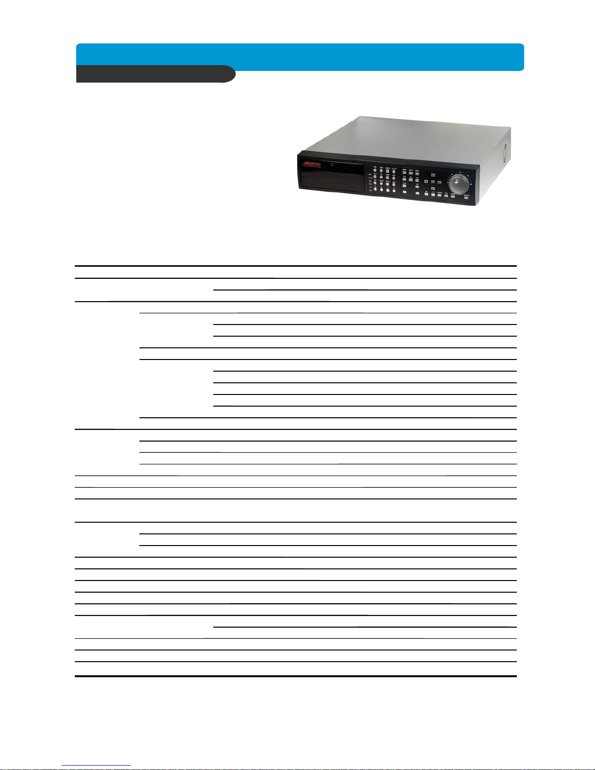
Best picture quality DVR
JPEG2000 Stand-alone DVR
59
CHAP. 7 Specifications
CHAP. 7 Specifications
• The best picture quality in Playback(JPEG-2000)
• Real time live display in all channels
• 4/8/16 channel video 240(200)ips recording capability
• Triplex (Recording/Playback/Ethernet)
• Multi-language menu
• Remote monitoring and download through network
• Convenient search function with Jog-shuttle
• VGA option available (Supporting TFT LCD Monitor)
• USB (Device) port for firmware upgrade
• Easy PTZ camera control by pre-assigned buttons
• Password Protection
• Remote Controller
Multiplex function Triplex (Record/Playback/Ethernet)
Storage Internal HDD Up to 2 HDDs with no limitation in capacity
Capacity CD-RW For Backup
Video Inputs Composite 4 CH: 4 Input / 8 CH: 8 Input / 16 CH: 16 Input
Outputs Composite 2Ch (Monitor / VCR)
VGA 1Ch (Supporting TFT LCD Monitor/Option)
Loop out
Compression JPEG-2000
Compression Rate Basic 12 KB/field(720x240/NTSC, 720x288/PAL)
(Image size fixed) Normal 16 KB/field(720x240/NTSC, 720x288/PAL)
Enhanced 20 KB/field(720x240/NTSC, 720x288/PAL)
Fine 24 KB/field(720x240/NTSC, 720x288/PAL)
Super Fine 28 KB/field(720x240/NTSC, 720x288/PAL)
Display Speed Real Time display
Recording Recording Mode Time, Motion, schedule, Alarm
/Search Search Event Search, Date/Time Search, Jog-Shuttle Search
Recording Speed 4CH: 60(Full mode)120(Dual mode); 8/16CH: 120(Full mode),240(Dual mode)
Recording Resolution Full (720x240/720x288), Dual (360x240/360x288)
Multi-language English, Spanish, German, Italy, France, Chinese….etc
Switching Interval 1~99 sec selectable
Live Division Screen 1 / 4 / 6 / 8 / 9 / 13 / 16 Split
Digital Zoom, Freeze function available in Live mode, PIP
Alarm Inputs 4CH: 4 Alarm / 8 CH: 8 Alarm / 16CH : 16 Alarm
Outputs 1 (NO/NC)
Post Alarm Duration of alarm output : 1 sec ~ 59 sec selectable
Motion Detection Area division : 16 x12 / Detection Division : 32 x 24
Network Ethernet(TCP/IP), Remote viewer program included
Backup VCR, CD-RW back-up, Download via IP Network
PTZ Control RS-485, Key Control(Key assigned for each PTZ command)
Firmware upgrade USB port for firmware upgrade, CD-R
Serial I/F RS-485 For PTZ camera control
RS-232C For operation using keyboard of PC
Power Requirements DC 12V 10A SWITCH POWER
Weight 8kg
Dimensions(WXHXD)mm 430mm(W) x 400mm(D) x 92mm(H)
Design and specifications are subjected to changes without notice
4 CH: 4 output / 8 CH: 8 output / 16 CH: 16 output
Page 61
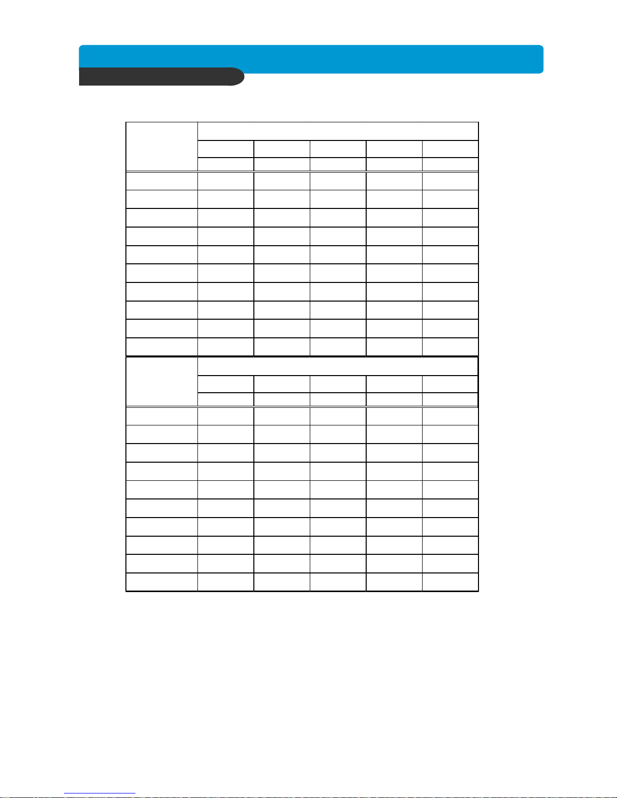
Best picture quality DVR
JPEG2000 Stand-alone DVR
60
Appendix
4CH Record time table
* Recording time based on continuous recording at full recording speed.
Bas ic Normal Enhanced Fine S uper Fine
12K 16K 20K 24K 28K
20
8.1Hr 6.1Hr 4.9Hr 4.0Hr 3.5Hr
40
16.2Hr 12.1Hr 9.7Hr 8.1Hr 6.9Hr
60
24.3Hr 18.2Hr 14.6Hr 12.1Hr 10.4Hr
80
32.4Hr 24.3Hr 19.4Hr 16.2Hr 13.9Hr
120
48.5Hr 36.4Hr 29.1Hr 24.3Hr 20.8Hr
160
64.7Hr 48.5Hr 38.8Hr 32.4Hr 27.7Hr
200
80.9Hr 60.7Hr 48.5Hr 40.5Hr 34.7Hr
250
101.1Hr 75.9Hr 60.7Hr 50.6Hr 43.3Hr
300
121.4Hr 91.0Hr 72.8Hr 60.7Hr 52.0Hr
400
161.8Hr 121.4Hr 97.1Hr 80.9Hr 69.4Hr
HDD
Capacity(GB)
NTSC
Bas ic Normal Enhanced Fine S uper Fine
14K 19K 24K 29K 32K
20
8.3Hr 6.1Hr 4.9Hr 4.0Hr 3.6Hr
40
16.6Hr 12.3Hr 9.7Hr 8.0Hr 7.3Hr
60
25.0Hr 18.4Hr 14.6Hr 12.1Hr 10.9Hr
80
33.3Hr 24.5Hr 19.4Hr 16.1Hr 14.6Hr
120
49.9Hr 36.8Hr 29.1Hr 24.1Hr 21.8Hr
160
66.6Hr 49.1Hr 38.8Hr 32.1Hr 29.1Hr
200
83.2Hr 61.3Hr 48.5Hr 40.2Hr 36.4Hr
250
104.0Hr 76.7Hr 60.7Hr 50.2Hr 45.5Hr
300
124.8Hr 92.0Hr 72.8Hr 60.3Hr 54.6Hr
400
166.4Hr 122.6Hr 97.1Hr 80.4Hr 72.8Hr
HDD
Capacity(GB)
PAL
Page 62
Best picture quality DVR
JPEG2000 Stand-alone DVR
61
Bas ic Normal Enhanced Fine S uper Fine
12K
16K 20K 24K 28K
20 4.0Hr
3.0Hr 2.4Hr 2.0Hr 1.7Hr
40
8.1Hr 6.1Hr 4.9Hr 4.0Hr 3.5Hr
60
12.1Hr 9.1Hr 7.3Hr 6.1Hr 5.2Hr
80
16.2Hr 12.1Hr 9.7Hr 8.1Hr 6.9Hr
120
24.3Hr 18.2Hr 14.6Hr 12.1Hr 10.4Hr
160
32.4Hr 24.3Hr 19.4Hr 16.2Hr 13.9Hr
200
40.5Hr 30.3Hr 24.3Hr 20.2Hr 17.3Hr
250
50.6Hr 37.9Hr 30.3Hr 25.3Hr 21.7Hr
300
60.7Hr 45.5Hr 36.4Hr 30.3Hr 26.0Hr
400
80.9Hr 60.7Hr 48.5Hr 40.5Hr 34.7Hr
HDD
Capacity(GB)
NTSC
Bas ic Normal Enhanced Fine S uper Fine
14K
19K 24K 29K 32K
20
4.2Hr 3.1Hr 2.4Hr 2.0Hr 1.8Hr
40
8.3Hr 6.1Hr 4.9Hr 4.0Hr 3.6Hr
60
12.5Hr 9.2Hr 7.3Hr 6.0Hr 5.5Hr
80
16.6Hr 12.3Hr 9.7Hr 8.0Hr 7.3Hr
120
25.0Hr 18.4Hr 14.6Hr 12.1Hr 10.9Hr
160
33.3Hr 24.5Hr 19.4Hr 16.1Hr 14.6Hr
200
41.6Hr 30.7Hr 24.3Hr 20.1Hr 18.2Hr
250
52.0Hr 38.3Hr 30.3Hr 25.1Hr 22.8Hr
300
62.4Hr 46.0Hr 36.4Hr 30.1Hr 27.3Hr
400
83.2Hr 61.3Hr 48.5Hr 40.2Hr 36.4Hr
HDD
Capacity(GB)
PAL
8/16CH Record time table
Appendix
 Loading...