

NEOSEN ENERGY EZI User Manual
EZI/STD CHARGING UNIT –
INSTALLATION
INTRODUCTION
This bulletin discusses the installation procedure for the EZI/STD Charging
Unit – Individual wireless charging transmitter.
OVERVIEW
The EZI/STD Charging Unit – Individual dual-mode transmitter is compliant
with PMA and WPC Qi standards.
The transmitter is tuned for best performance through!
8 mm (0.315") of non-conductive solid surface. Instructions for optimum
placement and installation are in this bulletin. Due to the precise routing

required the installation should be done in the fabrication shop prior to sheet
installation.
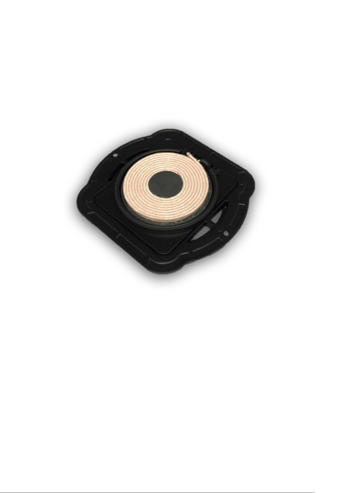
The EZI/STD Charging Unit – Individual package consists of the transmitter,
power cord and transformer. PMA-compliant charging rings are available
separately in packs of three: one ring each of micro USB, Apple 30-pin and
Apple Lightning® PMA compatible receivers.
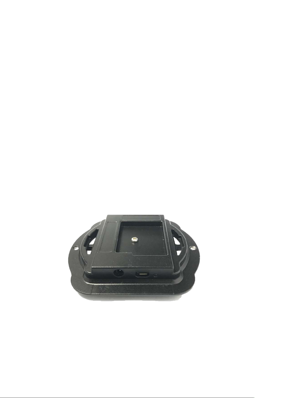
The transmitter has a micro USB port for updating the firmware if necessary.
A. PREPLANNING
A.1. Box Contents
The box will come with the transmitter and the power supply (not pictured
here).
A.3. Placement
There are several considerations regarding proper placement of the transmitter:
• Avoid putting in proximity to locations where the device being charged
may get wet, exposed to excessive heat or any other conditions which
may damage the device being charged. !
• Do not install next to heat sources (such as stoves) or where heat sources
are commonly used (toasters, hot plates, etc.). !
• Stay away from edges where charging devices can be easily knocked off
the surface. !
Work with the customer to determine convenient locations. Page 1 of 4 !
EZI/STD CHARGING UNIT – INSTALLATION
The transmitter requires a rectangular space of 82 mm x!
92 mm (3.23"x 3.60") below the surface counter. Allow an extra 25 mm (1")
distance to any support structure. No metal should be between the transmitter
and the surface. The transmitter also requires 36 mm (1 7/16") vertical clearance
measured from the top surface (24 mm (0.94") from bottom surface). Avoid
placement above heat- or moisture-generating appliances such as dishwashers,
warming drawers, wine refrigerators, etc. Verify cabinet/support measurements
before cutting the top. There should be a support strip between the transmitter
and any cutouts or the edge of the top.
The transmitter does generate some heat and ideally is installed such that it
shares airspace with the cabinet interior.
If placing above a drawer, make sure there is sufficient clearance, including
drawer contents.
Install so that the transmitter will be accessible by the customer. If there is a
warranty replacement the customer will need to be able to remove and replace
the transmitter. Make sure the power and micro USB ports will be accessible
after installation. Plan for power cable routing and mounting of the transformer.
The power supply has a 1.2 m (47") DC cable, 111 mm x 51 mm x 36 mm (4.4"
x 2.0" x 1.4") transformer and 1.2 m (47") AC cable. A four-unit power supply
is available separately.
If more than one transmitter is installed they should be at least 150 mm (6")
from each other.
 Loading...