

Page 1

Table of Contents
Health, safety and environment ...................................................................11
Precautions and Safety Issues.........................................................................1
End of Life........................................................................................................2
Functional description .................................................................................32
Installation .....................................................................................................43
Installation for the DS-75 and DS-85...............................................................4
Installation for the DS-90 and DS-90i...............................................................5
Installation for the Mailing (Franking) System..................................................7
Create Job ...................................................................................................104
Create Job on the DS-75...............................................................................10
Create Job on the DS-85...............................................................................12
Create Job on the DS-90...............................................................................14
Create Job on the DS-90i..............................................................................16
Create Job for the Mailing (Franking) System .........................................215
Create Job on the DS-75 for the Mailing (Franking) System..........................21
Create Job on the DS-85 for the Mailing (Franking) System..........................23
Create Job on the DS-90 for the Mailing (Franking) System..........................25
Create Job on the DS-90i for the Mailing (Franking) System.........................27
Fault finding ................................................................................................326
Fault finding....................................................................................................32
Specifications .............................................................................................337
Specifications.................................................................................................33
Page 2

Page 3

1
Health, safety and environment
Precautions and Safety Issues
Thoroughly read this operator manual, before using this system.
According to the EC declaration (European Commission) following the Lo w V oltage Directive
(2006/95/EC), this operator manual must be available in the national language(s) of the
country where the system is delivered.Therefore, if you do not have an operator manual
in your country’s language(s), contact your authorized distributor.
Warnings
• Disconnect the mains supply before performing any maintenance.
• Before connecting check if the system is suitable for the local mains voltage. Refer
to the type plate.
Safety Precautions
• The power connection must be easily accessible, preferably close to the system.
• Over-current protection in the equipment also relies on the branch circuit protection
(max. 20 A).
• The following part(s) is (are) considered the equipment disconnect device(s):
Power supply cord plug-
1
English
Conventions
A note gives additional relevant information.
Indicates the presence of a hazard that can cause personal injury
or property damage, if the hazard is not avoided.
1
Page 4

End of Life
1
English
The objectives of the European Community's environment policy are, in particular, to
preserve, protect and improve the quality of the environment, protect human health and
utilise natural resources prudently and rationally.That policy is based on the precautionary
principle and principles that preventive action should be tak en, that environmental damage
should as a priority be rectified at source.
Separate collection of waste is the precondition to ensure reuse and recycling of waste
that is generated at the disposal of electrical or electronical equipment and is necessary
to achieve the chosen level of protection of human health and the environment in the
European Community.
More particularly, certain materials and components of waste electrical and electronical
equipment needs selective treatment as their injudicious handling or disposing of on or into
land, water or air would represent a major threat to the environment and human health.
In order to facilitate collection and treatment separated from normal domestic waste,
electrical and electronical equipment is marked with the following logo:
Not only are you by law not allowed to dispose of the waste equipment via other
wastestreams, but w e encourage you to activ ely contribute to the success of such collection
and to the common good and better quality of life of present and future generations.
For more inf ormation on the correct disposal of this product please contact your local dealer.
2
Page 5
Functional description2
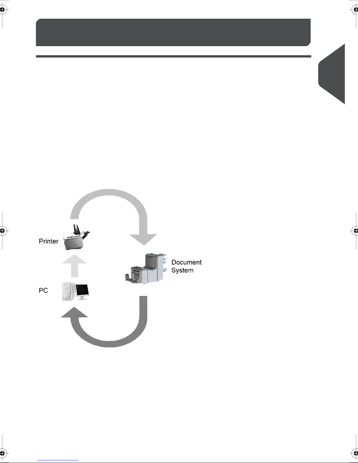
Mail Piece Production Control (MPPC) is an option availab le f or DS-75, DS-85, DS-90 and
DS-90i. It verifies the inserted documents or sets of documents with a database, which is
generated when printing the documents.The system will giv e a warning when a mail piece
is missing at the exit of the Document System.
During the printing process a 2D barcode is added to the address information of the
addresses.This barcode is added with the Print Machine software.The code will also
appear in the window area of the env elope as the document or set of documents is inserted.
At the exit of the Document System the window area of the envelope is scanned by a
camera, which is triggered by the Document System.The barcode information is send to
a PC.This PC is connected to the database (BSPI module) of the Print Machine software
to verify the ID in the barcode with the ID listing in the database.When an ID is
corresponding with the particular line in the listing, this line will get a verification tag. If an
ID is missing or if there is a misread, a warning will be placed in the listing.The system
can also be set to stop the Document System if this occurs.
2
English
3
Page 6
Installation for the DS-75 and DS-85
MPPC functionality uses a license code to be supplied by your dealer . See chapter ‘options’
3
English
in your operator manual for more information.
For both systems, DS-75 as well as DS-85, MPPC is supported in combination with the
HCVS-1. In this case no addintional installation of an MPPC unit is required as it is already
installed in the HCVS-1.
Preparation for the DS-75 and DS-85 with HCVS-1
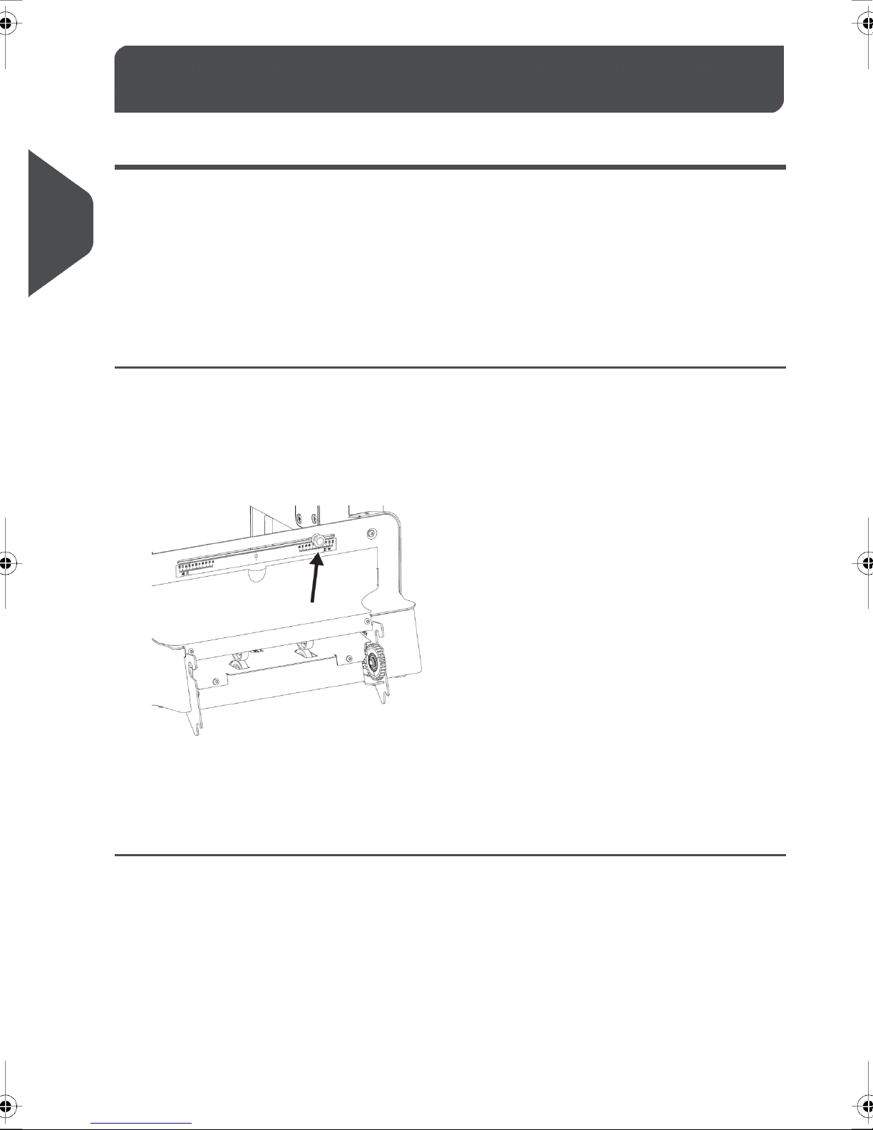
To ensure correct reading of the printed MPPC mark, align the MPPC camera in the High
Capacity Vertical Stacker.
Installation3
Loosen the knob on the back of the stacker.1.
2. Slide the camera sideways over the shaft to align it with the printed MPPC mark (see
Test and adjust MPPC DS-75 on page 11 or Test and adjust MPPC DS-85 on page
13).
3. Tighten the knob to secure the camera.
4
Page 7

Connecting cables on the DS-75 and DS-85
The Document System, camera unit and pc are connected through an interface box, the
MPPC unit. See the figure in this section. Make the following connections to the MPPC
unit:
3
Connect the cable attached to the camera to the port named ‘CAMERA I’.1.
2. Connect the cable from the port positioned on the back of the Document System to
the port named ‘INSERTER’.
3. Connect the cable from the com port of the PC to the port named ‘PC’
4. Connect the power supply to the socket named ‘5Vdc’.
Installation for the DS-90 and DS-90i
MPPC functionality uses a license code to be supplied by your dealer . See chapter ‘options’
in your operator manual for more information.
Preparation for the DS-90 and DS-90i
To ensure correct reading of the printed MPPC mark, align the MPPC camera. See the top
figure on this page for a DS-90/DS-90i with catch tra y and bottom figure for a DS-90/DS-90i
with conveyor belt.
English
Loosen the knob A located on the camera until you can slide the camera sideways.1.
5
Page 8
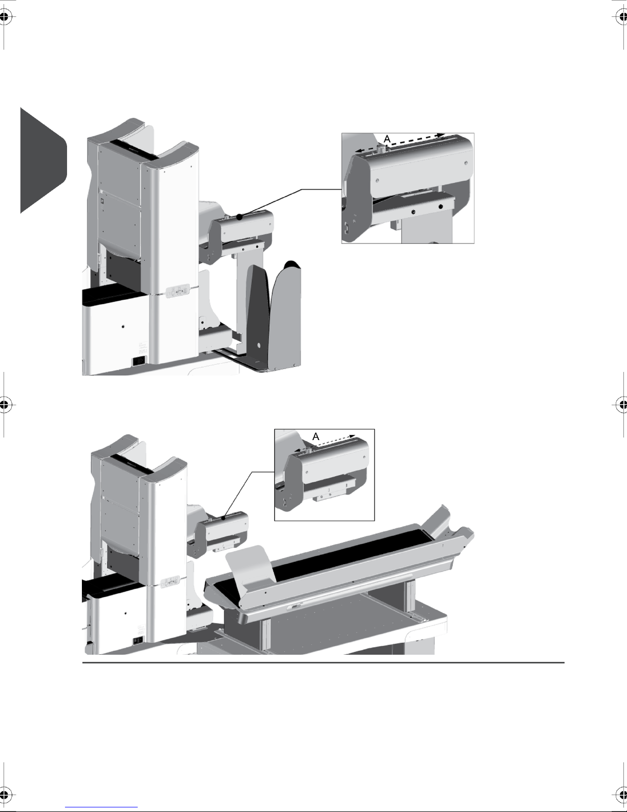
2. Slide the camera sideways over the shaft to align it with the printed MPPC mark (see
3. Tighten the knob A to secure the camera.
3
English
also Test and adjust MPPC DS-90 on page 15 or Test and adjust MPPC DS-90i on
page 18).
6
Page 9

Connecting cables on the DS-90 and DS-90i
The Document System, camera unit and pc are connected through an interface box, the
MPPC unit. See the figure in this section. Make the following connections to the MPPC
unit:
3
Connect the cable attached to the camera to the port named ‘CAMERA II’.1.
2. Connect the cable from the port positioned on the back of the Document System to
the port named ‘INSERTER’.
3. Connect the cable from the com port of the PC to the port named ‘PC’
4. Connect the cable from the exit sensor (mounted on the e xit of the Document System)
to the port named ‘Sensor’.
5. Connect the power supply to the socket named ‘5Vdc’.
6. In case that a CS-2 conve yor belt is used in the configuration it is necessary to connect
the cable from the conveyor to the port named ‘CS-2’.
Installation for the Mailing (Franking) System
MPPC functionality on the DS-75, DS-85, DS-90 and DS-90i with a Mailing (Franking)
System uses a license code to be supplied by your dealer. See chapter ‘options’ in your
operator manual for more information.
Preparation for the Mailing (Franking) System
English
To ensure correct reading of the printed MPPC mark, align the MPPC camera.
Loosen the knob A located on the camera until you can slide the camera sideways.1.
2. Slide the camera sideways over the shaft to align it with the printed MPPC mark.
7
Page 10

3. Tighten the knob A to secure the camera.
3
English
4. To get access to the Mailing (Franking) System (e.g. in case of paper jams) you can
lift the MPPC unit.
8
Page 11

Connecting cables on the Mailing (Franking) System
The Document System, camera unit and pc are connected through an interface box, the
MPPC unit. See the figure in this section. Make the following connections to the MPPC
unit:
3
Connect the cable attached to the camera to the port named ‘CAMERA II’.1.
2. Connect the cable from the port positioned on the back of the Document System to
the port named ‘INSERTER’.
3. Connect the cable from the com port of the PC to the port named ‘PC’.
4. Connect the cable from the com port of the Mailing (Franking) System to the port
named ‘INF’.
For the correct com port refer to the operator manual of y our Mailing
(Franking) System.
5. Connect the cable from the exit sensor to the port named ‘Sensor’.
6. Connect the power supply to the socket named ‘5Vdc’.
7. In case a CS-2 conveyor belt is used in the configuration, it is necessary to connect
the cable from the conveyor to the port named ‘CS-2’.
English
9
Page 12
Create Job4
Create Job on the DS-75
Activate MPPC
4
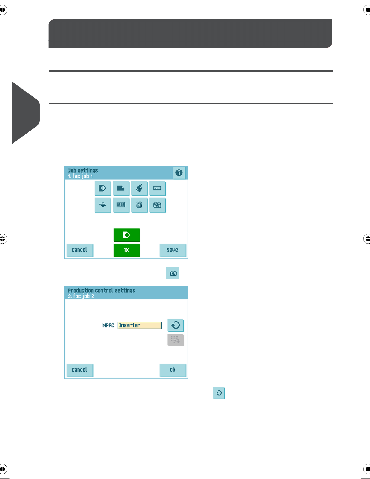
You can activate MPPC when you create or edit a job in the ‘job settings’ menu.
To activate MPPC in a job:
English
2.
Enter the ‘job settings’ menu (see operator manual).1.
In the ‘job settings’ menu select .
3.
In the ‘production control settings’ menu press to select ‘INSERTER’.
4. Press OK to confirm.
Now MPPC is switched on.
10
Page 13

Test and adjust MPPC
Before you use MPPC, test and adjust it.
When correct paper and envelopes are loaded and adjustments are correct (see
1.
operator manual), press the 1x button for a test run.A test run starts. A mail set is
transported to the stacker and stacked.If the produced mail set did not trigger the
camera, proceed as follows:
4
English
2. Remove the stacker cover.
3. Move the produced mail set from the stac ker tra y to the center of the tr ack behind this
cover.
4.
Press to test the MPPC camera position. If the red light flashes the camera is not
positioned correctly. If the camera is on the correct position it shows a green light.
5. If necessary adjust the camera position until the green light flashes.
6. Remove the mail set from the stacker track and close the cover.
7. Press the 1x button for a new test run.
8. Remove the mail set from the stacker after the test run.
11
Page 14

Create Job on the DS-85
Activate MPPC
You can activate MPPC when you create or edit a job in the ‘job settings’ menu.
To activate MPPC in a job:
4
English
2.
3.
Enter the ‘job settings’ menu (see operator manual).1.
In the ‘job settings’ menu select .
The ‘production control settings’ menu opens.
In the ‘production control settings’ menu press to select ‘INSERTER’.
Now MPPC is switched on.
4.
Press to confirm.
12
Page 15

Test and adjust MPPC
Before you use MPPC, test and adjust it.
1.
In the ‘job settings’ menu press to open the ‘test run’ menu.
When correct paper and envelopes are loaded and adjustments are correct (see
2.
operator manual) press for a test run. A test run starts. A mail set is produced
and transported to the exit.
4
English
If the produced mail set did not trigger the camera, proceed as follows:
3. Remove the stacker cover.
4. Move the produced mail set from the stac ker tra y to the center of the tr ack behind this
cover.
5.
Press to test the MPPC camera position.If the red light flashes the camera is
not positioned correctly. If the camera is on the correct position it sho ws a green light.
6. If necessary adjust the camera position until the green light flashes.
7. Remove the mail set from the stacker track and close the cover.
8.
Press the button for a new test run.
9. Remove the mail set from the stacker after the test run.
13
Page 16

Create Job on the DS-90
Activate MPPC
You can activate MPPC when you create or edit a job in the ‘job settings’ menu.
To activate MPPC in a job:
4
English
2.
3.
Enter the ‘job settings’ menu (see operator manual).1.
In the ‘job settings’ menu select .
The ‘production control settings’ menu opens.
In the ‘production control settings’ menu press to select ‘INSERTER’.
Now MPPC is switched on.
4. Measure the distance between the printed MPPC mark and the right side of the
envelope.
5.
Press next to the symbol to enter the measured distance.
6.
Press to confirm.
14
Page 17
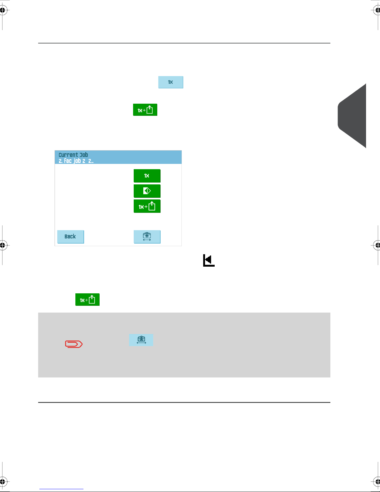
Test and adjust MPPC
Before you use MPPC, test and adjust it.
1.
In the ‘job settings’ menu press to open the ‘test run’ menu.
When correct paper and envelopes are loaded and adjustments are correct (see
2.
operator manual) press for a test run.
If the camera is not positioned correctly the red light flashes. Proceed as follows to
adjust the camera position:
4
A test run starts. A mail set is produced and transported to the exit.
3.
Hold the right side of the mail set against the mark on top of the MPPC unit.
4. Shift the camera so it is positioned exactly above the center of the MPPC mark (see
"Preparation for the Mailing (Franking) System" on page 13).
5.
Press for a test run. If the camera is adjusted correctly the g reen light flashes.
It is possible to manually check the correct position of the camer a.
Place a mail set (with the 2D barcode) in the exit below the camera.
English
Press . If the red light flashes the camera is not positioned
correct. Loosen the finger knob and shift the camera to the left or
right until the green light flashes. F asten the finger knob and perform
another test run.
6. Remove the envelope from the stacker after the test run.
15
Page 18

Create Job on the DS-90i
Process Mail Sets with MPPC
4
English
Select the Exit Settings.1.
2. Tap the [Advanced] button.
16
Page 19

3. Tap [MPPC] and select the MPPC mode: Inserter.
Other possibilities in the pull down menu are:
4
English
- Off; MPPC switched off
- Franking machine; MPPC with franking machine switched on
4. Measure the distance between the printed barcode and the right side of the envelope
(barcode offset).
5. Enter the 'Barcode offset'.
6. Tap [OK] to confirm.
17
Page 20

Test and adjust MPPC
Before you use MPPC, test and adjust it.
1.
4
English
In the idle screen tap [1x]. From the three 'test mail set' possibilities tap [Selected
exit].
Place a mail set (with the 2D barcode) in the exit below the camera. Hold the right
2.
side of the mail set against the mark as shown on top of the MPPC unit.
18
Page 21

3. Tap [Test] to test if the camera is aligned correctly with the barcode.
– A green light flashes: the camera is positioned correctly.
– A red light flashes: the camera is not positioned correctly.
4
English
If the camera is not positioned correctly, proceed as follows to adjust the camera
position:
4. Loosen the finger knob and shift the camera to the left or right until the green light
flashes.
5. Fasten the finger knob and remove the mail set.
6. Tap [Continue].The test mail set will be created.The system asks if the mail set is
OK or not OK and if MPPC is not OK.When you select mail set or MPPC not OK, y ou
are guided through a wizard that helps you to find the cause.
19
Page 22

7. Create another test mail set to verify the adjustment by tapping [1x] in the idle screen
4
English
again.
20
Page 23

5
Create Job for the Mailing
(Franking) System
Create Job on the DS-75 for the Mailing (Franking) System
Activate MPPC
You can activate MPPC when you create or edit a job in the ‘job settings’ menu.
To activate MPPC in a job:
Enter the ‘job settings’ menu (see operator manual).1.
2.
In the ‘job settings’ menu select .
The ‘production control settings’ menu opens.
5
English
3.
In the ‘production control settings’ menu press to select ‘Franking machine’.
Now MPPC is switched on.
21
Page 24

4. Measure the distance between the printed MPPC mark and the right side of the
5.
6. Press OK to confirm.
Test and adjust MPPC
Before you use MPPC, test and adjust it.
5
1.
English
envelope.
Press next to the symbol to enter the measured distance.
When correct paper and envelopes are loaded and adjustments are correct (see
operator manual), press the 1x button to test a mail set.
A test run starts. A mail set is produced and exited. If the camera is not positioned
correctly the red light flashes.
2.
Hold the right side of the mail set against the mark on top of the MPPC unit of the
Mailing (Franking) System.
3. Shift the camera so it is positioned exactly above the center of the MPPC mark (see
‘Preparation for the Mailing (Franking) System’).
4. Press the 1x button for a new test run. If the camera is adjusted correctly the green
light flashes.
22
Page 25

Create Job on the DS-85 for the Mailing (Franking) System
Activate MPPC
You can activate MPPC when you create or edit a job in the ‘job settings’ menu.
To activate MPPC in a job:
Enter the ‘job settings’ menu (see operator manual).1.
5
English
2.
In the ‘job settings’ menu select .
The ‘production control settings’ menu opens.
3.
In the ‘production control settings’ menu press to select ‘Franking machine’.
Now MPPC is switched on.
4. Measure the distance between the printed MPPC mark and the right side of the
envelope.
5.
Press next to the symbol to enter the measured distance.
6.
Press to confirm.
23
Page 26
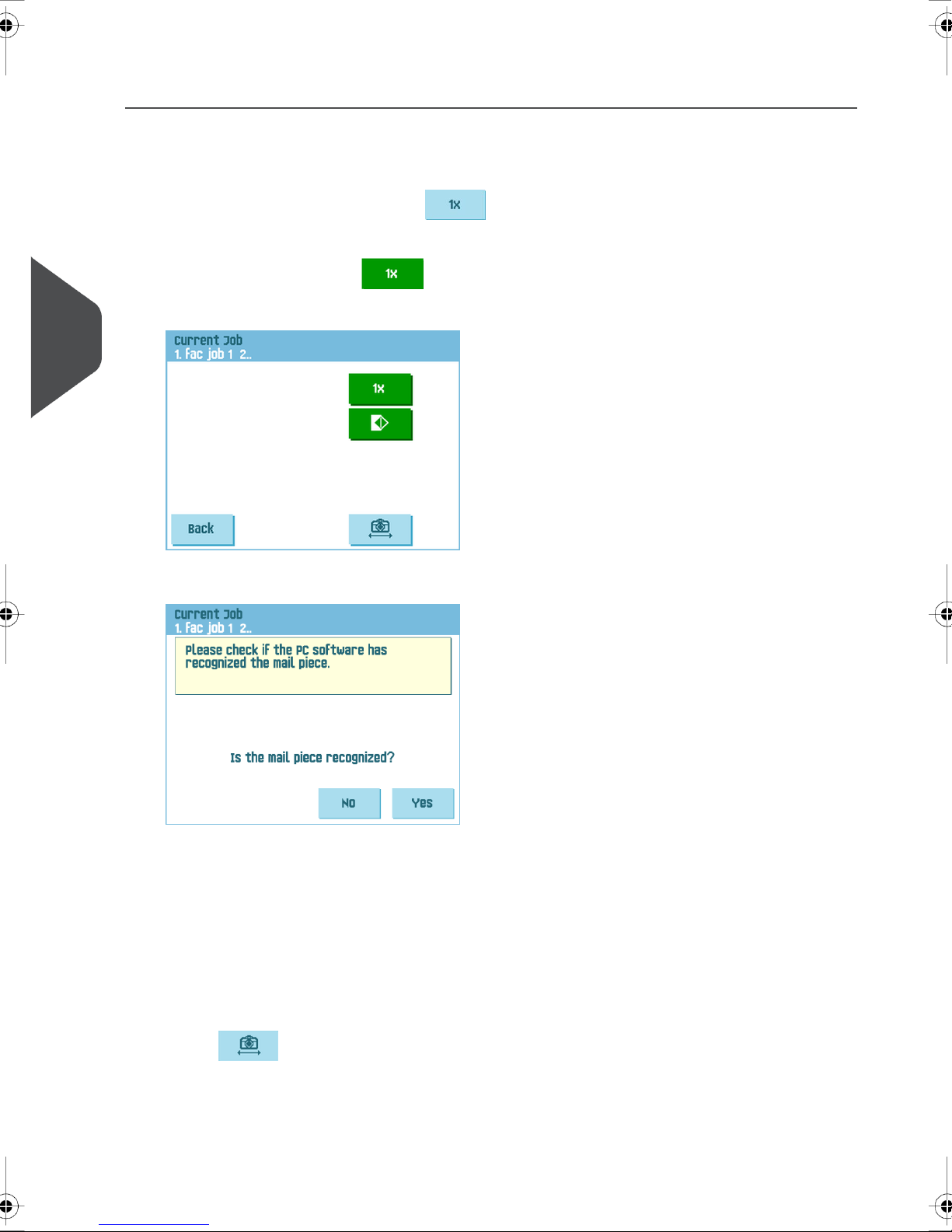
Test and adjust MPPC
Before you use MPPC, test and adjust it.
1.
2.
5
English
In the ‘job settings’ menu press to open the ‘test run’ menu.
When correct paper and envelopes are loaded and adjustments are correct (see
operator manual) press for a test run. A test run starts. A mail set is produced
and transported to the exit.
3. Follow the instructions on screen untill you are asked if the mail piece is recognized.
If the green light flashes the mail piece has been recognized. In that case press [Yes].
If the red ligth flashes the mail piece has not been recognized.The camera is not
correctly positioned. In that case press [No] which will open the 'test run' menu again
and proceed as follows:
4. Remove the stacker cover.
5. Move the produced mail set from the stac ker tra y to the center of the tr ack behind this
cover.
6.
Press to test the MPPC camera position.If the red light flashes the camera is
not positioned correctly. If the camera is on the correct position it sho ws a green light.
7. If necessary adjust the camera position until the green light flashes.
8. Remove the mail set from the stacker track and close the cover.
24
Page 27
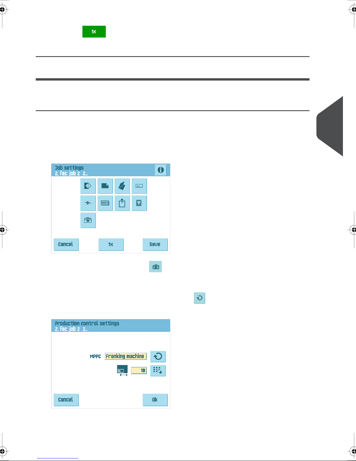
9.
Press the button for a new test run.
10. Remove the mail set from the stacker after the test run.
Create Job on the DS-90 for the Mailing (Franking) System
Activate MPPC
You can activate MPPC when you create or edit a job in the ‘job settings’ menu.
To activate MPPC in a job:
5
Enter the ‘job settings’ menu (see operator manual).1.
2.
In the ‘job settings’ menu select .
The ‘production control settings’ menu opens.
3.
In the ‘production control settings’ menu press to select ‘FRANKING MACHINE’
(MAILING).
English
Now MPPC is switched on.
25
Page 28
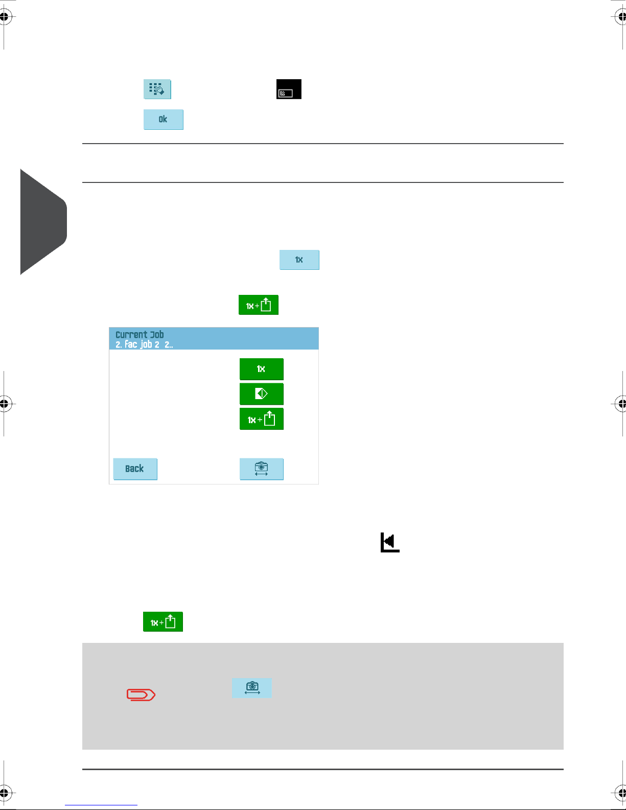
4. Measure the distance between the printed MPPC mark and the right side of the
5.
6.
Test and adjust MPPC
Before you use MPPC, test and adjust it.
5
1.
English
2.
envelope.
Press next to the symbol to enter the measured distance.
Press to confirm.
In the ‘job settings’ menu press to open the ‘test run’ menu.
When correct paper and envelopes are loaded and adjustments are correct (see
operator manual) press for a test run.
A test run starts. A mail set is produced and and stops under the camera. If the camera
is not positioned correctly the red light flashes.
3.
Hold the right side of the mail set against the mark on top of the MPPC unit of the
Mailing (Franking) System.
4. Shift the camera so it is positioned exactly above the center of the MPPC mark (see
‘Preparation for the Mailing (Franking) System’).
5.
Press for a test run. If the camera is adjusted correctly the g reen light flashes.
It is possible to manually check the correct position of the camer a.
Place a mail set (with the 2D barcode) in the exit below the camera.
Press . If the red light flashes the camera is not positioned
correct. Loosen the finger knob and shift the camera to the left or
right until the green light flashes. F asten the finger knob and perform
another test run.
26
Page 29
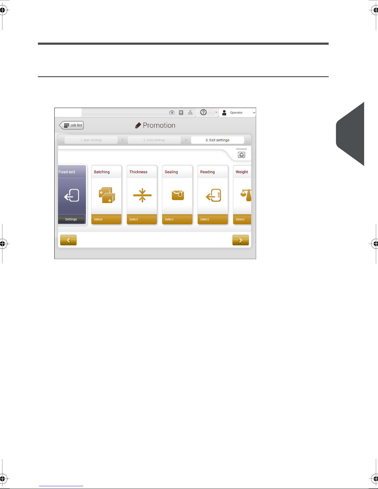
Create Job on the DS-90i for the Mailing (Franking) System
Process Mail Sets with MPPC
Select the Exit Settings.1.
5
English
2. Tap the [Advanced] button.
27
Page 30

3. Tap [MPPC] and select the MPPC mode: Franking machine.
5
English
Other possibilities in the pull down menu are:
- Off; MPPC switched off
- Inserter; MPPC switched on (inserter only)
4. Measure the distance between the printed barcode and the right side of the envelope
(barcode offset).
5. Enter the 'Barcode offset'.
6. Tap [OK] to confirm.
28
Page 31

Test and adjust MPPC
Before you use MPPC, test and adjust it.
In the idle screen tap [1x].From the three 'test mail set' possibilities tap [Selected
1.
exit].
5
English
2. You are asked if you want to frank the mail set.
Tab either [No] or [ Yes] and follow the instructions.
29
Page 32
3.
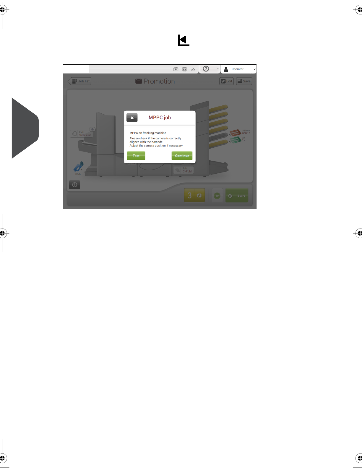
4. Tap [Test] to test if the camera is aligned correctly with the barcode.
5
English
Place a mail set (with the 2D barcode) in the exit below the camera. Hold the right
side of the mail set against the mark as shown on top of the MPPC unit.
– A green light flashes: the camera is positioned correctly.
– A red light flashes: the camera is not positioned correctly.
If the camera is not positioned correctly, proceed as follows to adjust the camera
position:
5. Loosen the finger knob and shift the camera to the left or right until the green light
flashes.
6. Fasten the finger knob and remove the mail set.
30
Page 33
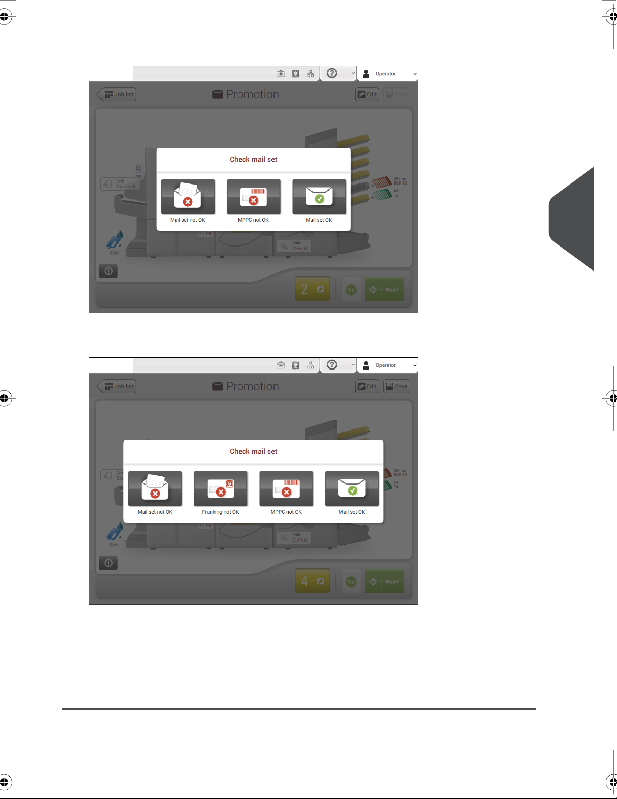
7. Tap [Continue].The test mail set will be created.
In case of franking the mail set has been set to [No] (refer to step 2) the system asks
if the mail set is ok or not ok and if MPPC is not ok.When y ou select mail set or MPPC
not ok, you are guided through a wizard that helps you to find the cause.
5
English
In case of franking the mail set has been set to [Yes] (refer to step 2) the system asks
if the mail set is OK or not OK, if MPPC is not OK or Franking is not OK.When you
select mail set, MPPC or Franking not OK, y ou are guided through a wizard that helps
you to find the cause.
8. Create another test mail set to verify the adjustment by tapping [1x] in the idle screen
again.
31
Page 34

Fault finding6
Fault finding
InfoActionMessage
No ID
Invalid ID
6
Duplicate ID
English
ID's out of sequence
PC saving problem
PC problem
envelopes
Remove en velope and check
why envelope ID number is
unknown to MPPC
Remove en velope and check
why envelope has a previously used ID
Remove en velope and check
envelope sequence or restart
the MPPC
Check BSPI application for
details
Check BSPI application for
details
Scanner did not read an IDCheck scanning position on
The ID of the last envelope is
unknown to BSPI
The ID of the last envelope
was already processed before by BSPI
The ID of the last envelope is
out of sequence with previous
ones
BSPI cannot save the ID of
the last envelope in its database
The BSPI application encounters a problem
Check cables and connectorsNo communication
Communication error
between Document System,
scanner or BSPI PC
32
Page 35

Specifications7
Specifications
Used for systemMPPC
DS-90, DS-90iMPPC-V2
DS-75, DS-85MPPC-V3
MPPC-INF
Mailing (Franking) System for the DS-75,
DS-85, DS-90 and DS-90i
7
English
33
 Loading...