

Page 1
PRINTER
830/930
USER'S GUIDE
Page 2

Products presented in this guide are conform to
requirements of directives nbr 73/23/CEE and
89/336/CEE.
Neopost has implemented a program for the
recycling of worn machines and machines at the
end of their lifetime. Contribute in a responsible
way to the environmental protection by consulting
your retailer internet site, or by contacting him.
He will inform you of the collection and treatment
processes of these machines.
Page 3

Issue 22/05/2008 - 4136119G/B
Page 4
PRINTER 830/930
Operating Manual
Page 5

© Copyright 2008
All rights reserved. This manual may not be reproduced in whole or in part, trans-
ferred, stored in a telemetry system or translated into any language, in whatsoever
form, without prior written permission.
The manufacturer assumes no liability for damages occurring as a result of misuse,
repairs and modifications, which are carried out by unauthorized third parties. This
manual has been prepared with great care. However, liability is excluded for any
errors occurring in spite of such care. In his commitment to continuous improvement, the manufacturer reserves the right to implement further technical and optical changes. The values herein provided are nominal values. Therefore, no legal
claims may be raised in connection with this manual.
The manufacturer cannot be held liable for damages or malfunctions caused by options or accessories, when these are not original products or when they have not
been expressly approved by the manufacturer.
Brand:
HP is a registered brand name of Hewlett-Packard Corporation.
Microsoft and Windows are registered brand names of Microsoft Corporation.
2
Page 6

Table of Contents
Table of Contents ....................................................................................... 3
Illustration Directory.................................................................................. 6
1 Introduction.......................................................................................... 8
1.1 Pictograms ............................................................................................... 8
1.2 Notes for the Use of this Manual..................................................................9
1.3 Important Terms and Abbreviations .............................................................9
1.4 System Requirements................................................................................9
2 Safety Notes ....................................................................................... 10
2.1 General Safety Notes ............................................................................... 11
2.2 Handling Ink Cartridges............................................................................ 13
2.3 Location of the Printer..............................................................................13
2.4 Disposal................................................................................................. 13
3 Transport and Packaging .................................................................... 14
3.1 Shipping ................................................................................................ 14
3.2 Unpacking the Printing ............................................................................. 14
3.3 Assembly ...............................................................................................15
4 Printer Description.............................................................................. 16
4.1 Machine Overview ................................................................................... 16
4.2 Range of Application ................................................................................ 17
4.3 Operation............................................................................................... 18
4.4 The Control Panel.................................................................................... 18
4.4.1 Keyboard Description................................................................... 18
4.4.2 Key Combinations .......................................................................19
4.5 The Display ............................................................................................ 20
4.5.1 Offline Mode............................................................................... 20
4.5.2 Online Mode............................................................................... 21
4.6 Brief Instructions..................................................................................... 21
5 Start-Up and Operation....................................................................... 22
5.1 Setting Up and Connecting the Printer........................................................22
5.2 Installing the Driver................................................................................. 23
5.2.1 Installation of the parallel virtual connection ................................... 24
5.2.2 Check the Correct Device Recognition ............................................25
5.2.3 Removal of Already Installed Driver............................................... 26
5.2.4 Installation of the Connected Printer.............................................. 27
3
Page 7

5.2.5
Adding a New Printer................................................................... 28
5.3 Inserting the Ink Cartridge ....................................................................... 32
5.3.1 Correctly Inserting the Ink Cartridge.............................................. 33
5.3.2 Resetting the Ink Counter ............................................................ 34
5.3.3 Display for the Change of Ink Cartridge.......................................... 34
5.3.4 Set the ink Counter..................................................................... 35
5.3.5 Cleaning the Ink Jets................................................................... 36
5.4 Print job Setup........................................................................................ 36
5.4.1 Setting Media Widths for the Machine.............................................36
5.4.2 Setting the Print Format............................................................... 39
5.4.3 Checking the Paper Transport....................................................... 42
5.5 Test Print............................................................................................... 42
5.6 Machine Counters.................................................................................... 43
5.6.1 Day Counter............................................................................... 43
5.6.2 Service Counter.......................................................................... 43
5.6.3 Counting of Job Pages.................................................................. 44
6 The Programming Mode.......................................................................45
6.1 Purpose of the Programming Mode............................................................. 45
6.2 The Control Panel in the Programming – Offline- Mode.................................. 45
6.3 Keyboard Layout in the Programming Mode.................................................46
6.4 Menu Overview....................................................................................... 48
6.5 Explanation of the Individual Menus........................................................... 50
6.6 Job Parameter ........................................................................................ 53
6.7 Service .................................................................................................. 57
6.8 Language............................................................................................... 60
6.9 Setting .................................................................................................. 60
6.9.1 Example of an Application in the Programming Mode........................ 60
6.9.2 Initialization of the Machine.......................................................... 61
7 Troubleshooting ..................................................................................62
7.1 The Meaning of Some of the Display Notes.................................................. 62
7.2 Error Messages .......................................................................................63
7.3 Warning Messages................................................................................... 65
8 Appendix .............................................................................................66
8.1 Maintenance Notes .................................................................................. 66
8.1.1 Cleaning the Ink Cartridge............................................................ 66
8.1.2 Press Roll and Rollers .................................................................. 66
8.2 Interfaces .............................................................................................. 66
4
Page 8

8.2.1
Centronics Parallel Interface .........................................................67
8.2.2 RS-232-C Serial Interface.............................................................69
8.3 Fonts..................................................................................................... 71
8.3.1 Terminology ............................................................................... 71
8.3.2 Character Set ............................................................................. 75
8.3.3 Selection of the Fonts for Printing.................................................. 76
8.4 Character Sets........................................................................................77
8.4.1 7-Bit Character Sets.................................................................... 77
8.4.2 8-Bit Character...........................................................................83
8.5 Side Guide..............................................................................................87
8.6 Accessories............................................................................................. 88
8.7 Technical Data ........................................................................................ 89
9 Glossary.............................................................................................. 90
10 Index.................................................................................................. 94
5
Page 9

Illustration Directory
Illustration 3-1: PRINTER 830/930 assembly.............................................................. 15
Illustration 4-1: PRINTER 830/930 back side.............................................................. 16
Illustration 4-2: PRINTER 830/930 front side.............................................................. 17
Illustration 4-3: Control panel.................................................................................. 18
Illustration 4-4: Display indications........................................................................... 20
Illustration 5-1: Changing the fuses.......................................................................... 22
Illustration 5-2: USB Compound device setup............................................................. 24
Illustration 5-3: USB Compound device setup............................................................. 24
Illustration 5-4: Device Manager .............................................................................. 25
Illustration 5-5: Remove USB driver ......................................................................... 26
Illustration 5-6: Remove USB driver ......................................................................... 26
Illustration 5-7: Calling up the Device Manager .......................................................... 27
Illustration 5-8: Device Manager connection............................................................... 27
Illustration 5-9: Add printer..................................................................................... 28
Illustration 5-10: Add printer................................................................................... 28
Illustration 5-11: Add printer................................................................................... 29
Illustration 5-12: Printer installation assistant ............................................................ 29
Illustration 5-13: Printer installation assistant ............................................................ 29
Illustration 5-14: Printer installation assistant ............................................................ 30
Illustration 5-15: Printer installation assistant ............................................................ 30
Illustration 5-16: Printer installation assistant ............................................................ 30
Illustration 5-17: Printer installation assistant ............................................................ 31
Illustration 5-18: Printer installation assistant ............................................................ 31
Illustration 5-19: Printer installation assistant ............................................................ 32
Illustration 5-20: Check printer installation................................................................ 32
Illustration 5-21: Open locking lever......................................................................... 33
Illustration 5-22: Inserting the ink cartridge .............................................................. 34
Illustration 5-23: Close locking lever......................................................................... 34
Illustration 5-24: Ink supply display.......................................................................... 36
Illustration 5-25: Set printer.................................................................................... 37
Illustration 5-26: Height adjustment of the pickup rollers............................................. 37
Illustration 5-27: Setting the separating finger........................................................... 38
Illustration 5-28: Setting the print position for the address .......................................... 39
Illustration 5-29: Setting the print position for the address .......................................... 39
Illustration 5-30: Setting the print object format ........................................................ 41
Illustration 5-31: Setting the print object format ........................................................ 41
Illustration 5-32: Setting the guide bracket................................................................ 42
Illustration 5-33: Setting the dosing roll.................................................................... 43
Illustration 6-1: Keyboard layout for the programming mode........................................ 46
Illustration 6-2: Test Print of all cartridges................................................................. 58
Illustration 6-3: Test Print of all jets ......................................................................... 58
6
Page 10

Illustration 6-4: Test print with defective jets............................................................. 59
Illustration 8-1: Cleaning the cartridge...................................................................... 66
Illustration 8-2: Parallel interface connector socket ..................................................... 67
Illustration 8-3: Parallel interface pulse diagram......................................................... 69
Illustration 8-4: Serif and sans serif.......................................................................... 71
Illustration 8-5: Fixed character spacing.................................................................... 72
Illustration 8-6: Proportional character spacing...........................................................72
Illustration 8-7: Character size.................................................................................73
Illustration 8-8: Print direction................................................................................. 74
Illustration 8-9: 7-Bit character set Ger7................................................................... 75
Illustration 8-10: 8-Bit character set PC8................................................................... 76
Illustration 8-11: Divert mechanism.......................................................................... 88
7
Page 11
1 Introduction
With the PRINTER 830/930 you have an innovative digital printer with HP ink jet
technology for printing variable data - for printing mass mailings, for example, with
addresses, serial numbers or other variable information and graphic elements. The
machine has been designed for professional use with high performance.
In order to ensure both long service life of PRINTER 830/930 and its
components, as well as safe conditions of use, we recommend that
you read carefully and comply with the operating instructions and
safety notes. Always be aware of all warnings and notes that are affixed to or printed on the machine itself.
All persons who are to handle this machine must also be familiar with the operating
manual.
Store this manual in a safe place where it is easily accessible for future reference at
any time.
1.1 Pictograms
General Warnings
Warning of danger from electricity or electrical shock
Information / Note indicating important information regardin g the
handling of the machine.
8
Page 12

1.2 Notes for the Use of this Manual
The following sections provide all the general informat ion and explanations required, in order to be able to carry out the subsequent tasks and procedures..
When some action is expected from the assembler or operator, the text is always
preceded by a dot, for example:
• First step.
• Next step.
Please, always read through to the action texts, so th at you will obtain all of the
necessary information. Do not anticipate what y ou believe will follow in the manual:
It will prevent you from making mistakes!
Chronology and Reference
This manual is structured chronologically, and therefore ordered sequentially from
the receipt of the machine packed up to its ready-for-use state. This is follow ed by
information for operation, programming, and then fin a lly technical data.
When you are unfamiliar with the machine, it is best to read through the manual
from beginning to end. You will be guided step by step, and in this way, you can
easily and quickly have the machine in operation.
If you are already familiar with the PRINTER 830/930, it will make things easy if
you to use this manual as a reference work.
1.3 Important Terms and Abbreviations
There are a few terms and abbreviations you need to know, in connection with the
PRINTER 830/930:
• Cartridge = Crt = C, C1, C2, C3.
• Printing unit = Unit = U, U1,
We refer to one unit here, since three cartridges have been combined.
• Paper width = Extension of the medium to be printed in the transport direc-
tion.
• Paper height = Extension of the medium to be printed crosswise to the trans-
port direction.
• Print object width = Extension of the print object in the transport direction.
• Print object height = Extension of the print object crosswise to the transport
direction.
• The print object is the medium to be printed.
1.4 System Requirements
The PRINTER 830/930 is designed for use on a PC (at least Pentium 200 MHz) with
parallel interface. It can be run with the Windows 2000 or Windows NT4 or Windows XP operating systems.
The interface cable must be a shielded twisted-pair parallel interface cable.
As an alternative, the printer can be connected with a USB cable, when using Win-
dows 2000 and Windows XP.
9
Page 13

2 Safety Notes
For your own safety and the proper functioning of the machine, please, read carefully the following instructions, before st arting your machine. Always be aware of all
warnings and notes that are affixed to or printed on the machine itself. Store this
manual in a safe place where it is easily accessible for future reference, at any
time.
The address PRINTER 830/930 is a state-of-the-art construction and reliable in operation. Nevertheless, the device may present hazards when operated by untrained
personnel. The same applies to use that is inappropriate and not in keeping with its
intended purpose.
Failure to comply with this manual’s instructions might result in:
• an electrical shock,
• injuries due to the rotating rollers,
• damage to the machine.
10
Page 14

2.1 General Safety Notes
Caution!
Please, read these notes with care.
Save this manual for future reference.
All notes and warnings found on the machine are to be followed.
Installing the
Machine
A safe, level position is necessary, when installing the machine.
Injuries may be caused by tipping, rolling away or falling.
The machine is to be protected from moisture.
WARNING!
This is a Class A device. This device may cause radio frequency
disturbances in residential areas; in this case, the operator may
be required to implement the necessary corrective measures.
Electrical
Hazards
Depending upon the country-specific version, the address
PRINTER 830/930 may only be connected to either a voltage of
230 V/50 Hz or 115 V/60 Hz.
The mains plug may only be connected with a socket having an
installed protective contact! The protective effect may not be
compromised by the use of an extension line without a protective
grounding conductor. All interruptions of the protective grounding conductor, within or outside of the machine, are prohibited.
The device is double pole fused! When fuse failure occurs, electrical machine parts can still carry voltage.
When making the connection to the mains power, be aware of
the connection values on the rating plate.
Inspect the voltage setting on the device’s power unit.
Run the power cords in such a way, that no-one may trip over
them. Do not place any objects upon the power cord.
When the machine is not in use over a long period of time, it
should be disconnected from the power supply in order to avoid
any damage in the event of a voltage surge.
Protect the device from moisture. When moisture enters the machine, there is a danger of electrical shock.
Never open the machine. For reasons of electrical safety, the
machine should only be opened by authorized service personnel.
Operating
Safety
Never put your hands inside the machine when it is running!
The danger of injuries exists, through pulling in and crushing on
the rotating rollers. In addition, keep long hair and parts of loose
clothing far from the machine in operation.
In order to prevent damage to the machine, only factory authorized accessory parts should only be used.
Cleaning the
Machine
Prior to cleaning the machine, it should be disconnected from the
mains outlet.
When cleaning the machine, do not use liquid or spray cleaners,
but only a cloth dampened with water.
11
Page 15

Allow the
Machine to
be Inspected
by the Service Partner!
In the following cases, you should unplug the machine from the
mains and contact an authorized service technician:
• When the power cord or its plug is worn or damaged.
• When water or other liquid has entered the device.
• When the device does not function properly, in spite of
following the instruction provided.
• When the device has fallen down or the housing is damaged.
• When there is a significant change in the performance of
the machine.
Spare Parts When repair work is carried out, only original spare parts or
spare parts approved by the manufacturer may be used.
Repairs Do not disassemble the machine any further than is described in
this manual. The opening of the machine by unauthorized personnel is not permitted. Repairs may only be carried out by authorized service personnel.
Modification is not permitted:
For safety reasons, your own reworking and modifications are
not permitted.
The PRINTER 830/930 is a Class A device. This device may
cause radio frequency disturbances in residential areas; in this
case, the operator may be required to implement the necessary
corrective measures.
12
Page 16

2.2 Handling Ink Cartridges
Store ink cartridges out of the reach of children. Normally, no ink
leakage can occur. Immediately wash off sprays of ink from the skin
under running water. Should ink get into the eyes, rinse it out immediately with sufficient water.
The ink cartridge should not be shaken, allowed to fall, or hit with the hand or a
hard surface.
Install the ink cartridge immediately after removing the protective strip. The expiration date may not be exceeded.
Do not attempt to open or refill an ink cartridge. This can damage the machine.
Clean the ink cartridge as described in chapter
8.1 – “Maintenance Notes”.
2.3 Location of the Printer
Be aware when installing the machine that it must stand on a smooth and level surface that is larger than the printer.
The floor space for the printer must be sufficiently stable. The tipping over or falling
of the machine can lead to injuries, as well as damage to the machine.
When selecting the installation or storage location for the printer, keep in mind that
it must be protected from strong temperature and humidity changes, direct sunlight
and excessive heat.
The printer must not be subject to vibrations or shocks.
Install the printer near a mains outlet, so that the power cord can be disconnected
trouble-free at all times.
2.4 Disposal
The printer may not be disposed of in the conventional manner of household waste.
Please, dispose of the printer in accordance with the regulations in force.
13
Page 17

3 Transport and Packaging
3.1 Shipping
The PRINTER 830/930 is shipped in packaging designed for the purpose of delivery
at its intended destination, via regular transportation, in undamaged condition .
The forwarding agent is liable for damages occurring in transit. Transport and storage should take place under normal conditions, i.e. at temperatures between +5°C
and +70°C, and maximum relative humidity of 80%. During unauthorized conditions, damage may occur that is not outwardly visible.
3.2 Unpacking the Printing
Remove all packaging and take out the device with accessories. Check to see, if all
parts of the printer according to the following list are present in total and in undamaged condition:
• 1 PRINTER 830/930
• 2 Side guides, short
• 1 Side guide, middle (Optional for the Printer 830)
• 1 Side guide, long (Optional for the Printer 830)
• 1 Stack extension
• 1 Guide bracket
• 1 Printer driver & User Guide CD
• 1 Power cord
• 1 USB / Parallel interface cable
• 3 ink cartridges
Should you not have any need for the packaging – e.g. sending it back for maintenance purposes – dispose of it in an environmentally friendly manner.
14
Page 18
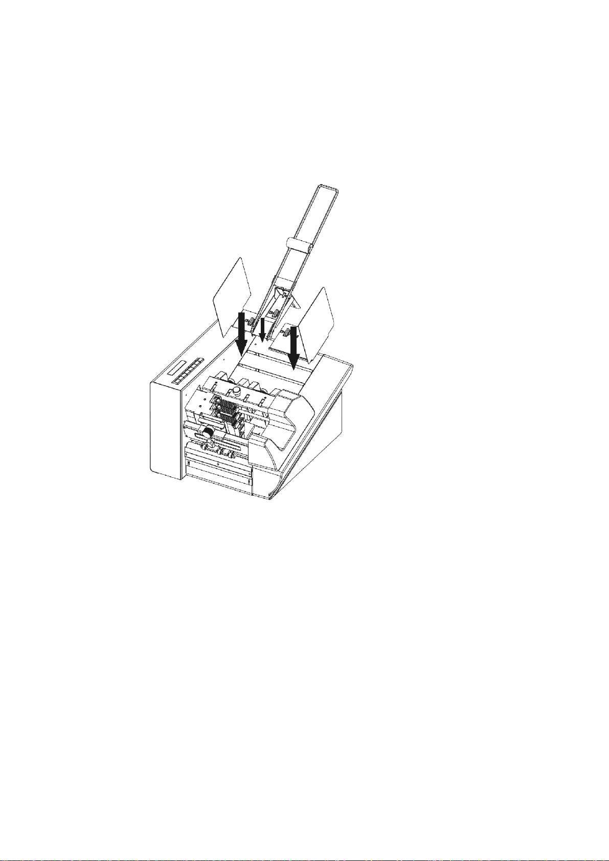
3.3 Assembly
Assembly of the Paper Support Plate and Side Guide
1. Set the side guide in the lower metal opening and lock in place with a quarter
turn of the bayonet coupling.
2. In the same manner, set the guide bracket in the upper metal opening.
Illustration 3-1: PRINTER 830/930 assembly
15
Page 19
4 Printer Description
4.1 Machine Overview
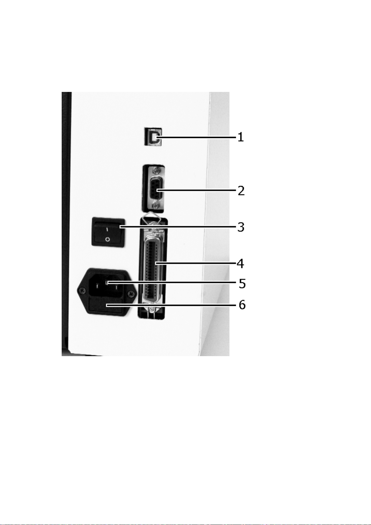
Illustration 4-1: PRINTER 830/930 back side
1. USB Connection
2. Serial Status Connection
3. ON/OFF Switch
16
4. Printer Parallel Cable Connection
5. Power cord Connection
6. Fuse holder
Page 20
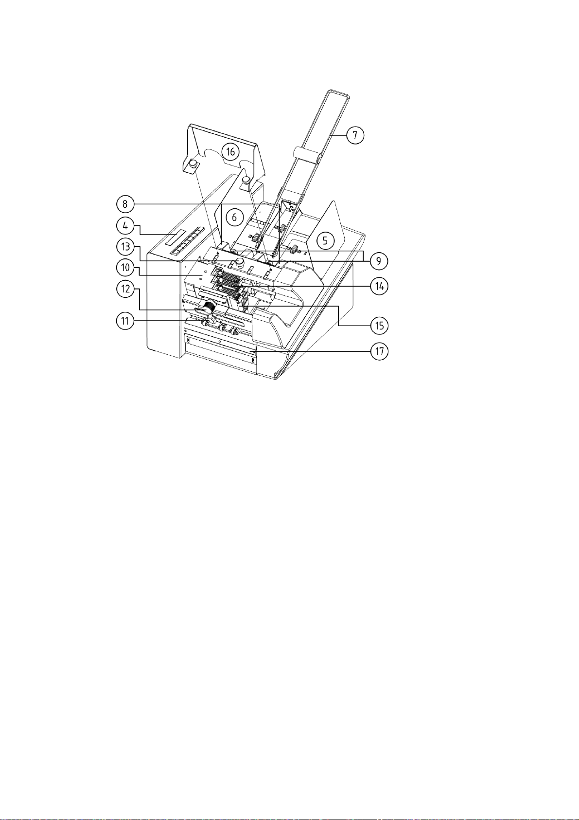
Illustration 4-2: PRINTER 830/930 front side
1. Control panel with display
2. Side guide middle
3. Side guide short
No ill.: Side guide long
4. Guide bracket
5. Separator
6. Knurled screw separator
7. Printing unit
4.2 Range of Application
The PRINTER 830/930 is a high speed & high quality ink jet printer. It prints correctly positioned addresses on various print objects such as letter envelopes, letterheads, cards, prospectuses and newspapers up to:
• Minimum
140 mm x 70 mm with a thickness of 0.1 mm
• Maximum
Printer 830: 508 mm x 355 mm with a thickness of 2 mm
Printer 930: 508 mm x 355 mm with a thickness of 6.3 mm
The maximum printing surface is 508 mm in width and 38 mm in height (equivalent
to 9 lines with a font-size of 12 pt with a line spacing of 12 pt) .
8. Knurled screw printing unit carriage
9. Printing unit height adjustment
10. Knurled screw height adjustment
outfeed rollers
11. Locking lever f. ink cartridge
12. Ink cartridge
13. Stack extension
14. Discharge brush cpl, optional
17
Page 21
4.3 Operation
The PRINTER 830/930 is designed for operation on an IBM-compatible PC. Printing
can be carried out from most word processing, database and address processing
programs.
The printer has a printing unit with three HP ink cartridges. This allows the printing
of addresses with no movement of the printing unit itself.
The print object is - exactly positioned by the side guide - inserted above the printing unit. Printing is carried out when the print object passes u nder the printing unit.
The direction of the font is always initially in the transport direction; the print can
be readable from the front or rotated by 180°.
As a rule, the positioning of the address in height is carried out by moving the
printing unit. The positioning of the address in width may be carried out either via
the software on the PC or settings on the printer.
The operation is very simple. For the first start-up, you will require abou t 30 minutes.
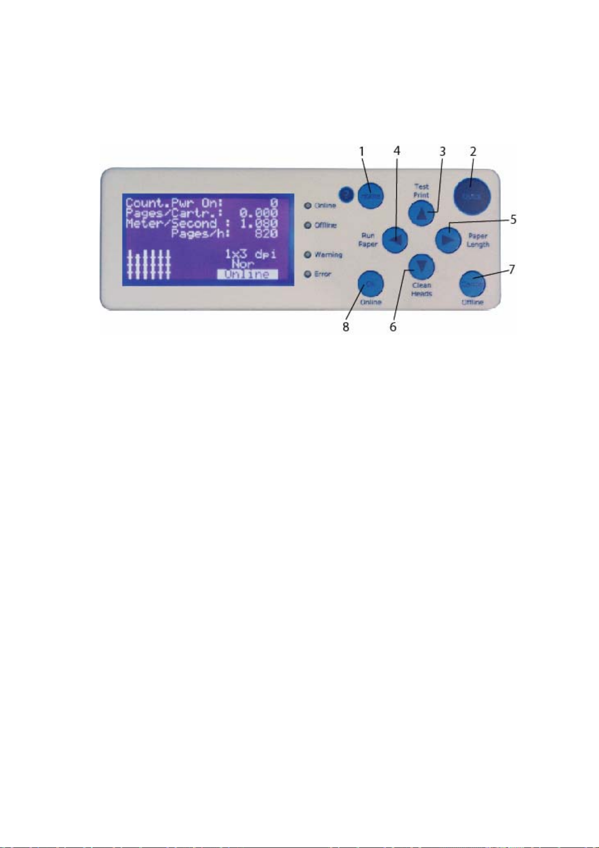
4.4 The Control Panel
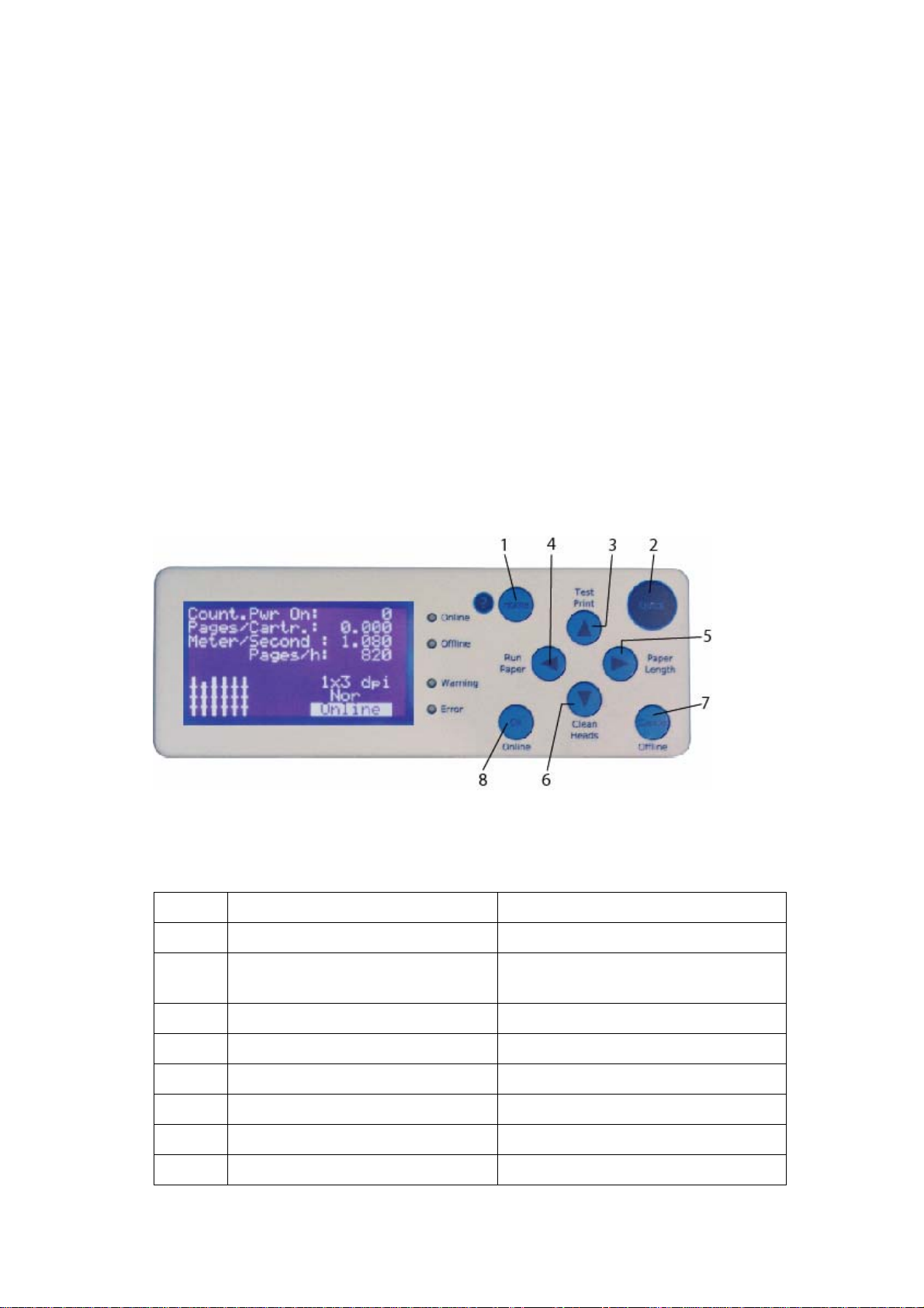
Illustration 4-3: Control panel
4.4.1 Keyboard Description
Only in the Offline Mode
Keys Key (X) alone Together with “Quick” Key
1 Home = Main Menu
2 Quick Menu =To find important
functions very fast
3 Arrow up Start Test Print
4 Arrow left Run Paper
5 Arrow right Measure Paper Length
6 Arrow down Purge Cartridges
7 Cancel / Offline Mode
8 OK (Confirm) / Online Mode
18
Page 22
LED Functions
Green LED = Online Blue LED = Offline
Orange LED= Warning Red LED = Error
In online mode the printer can only be switched to off line by pressing the “Offline”
(7) button.
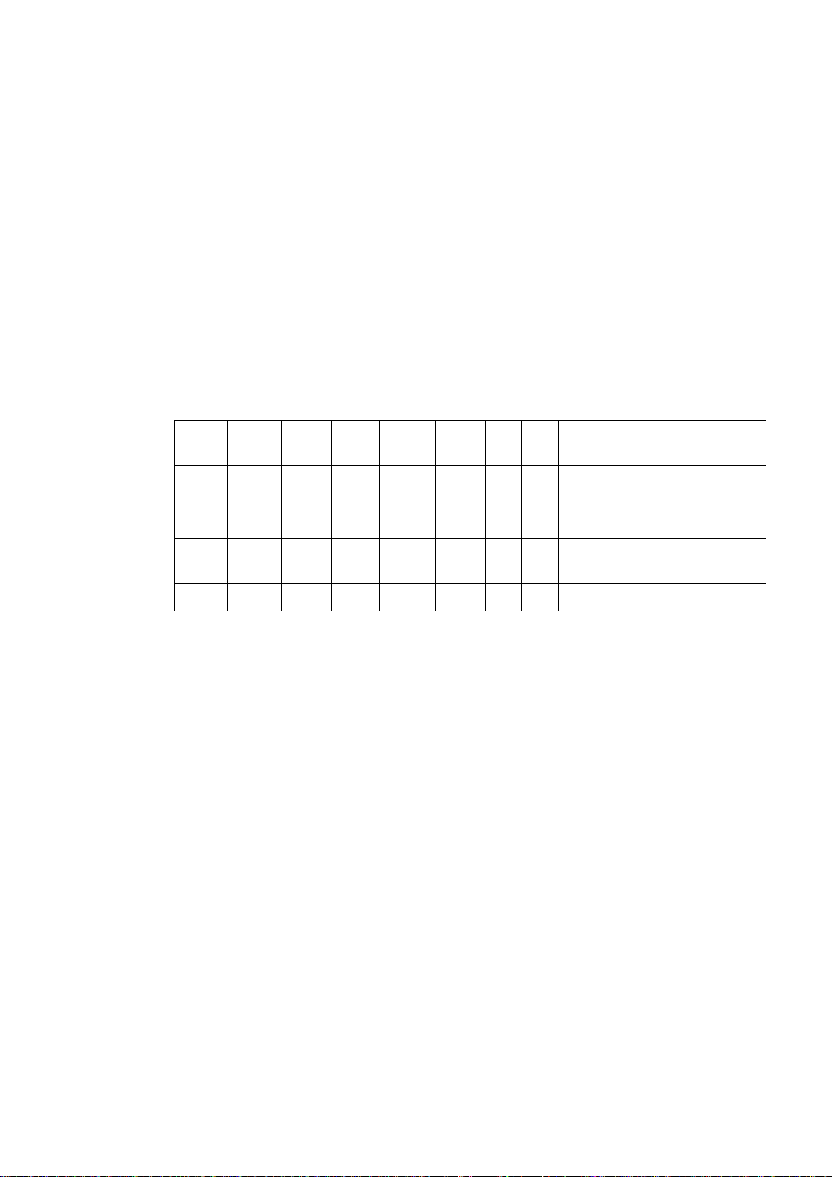
4.4.2 Key Combinations
The key combinations have, in connection with the switching on of the machine, the
following functions:
Power
Home Quick OK Cancel Down Up Left Right Description
on
X X
X X
X X X X
X X X X X
Note:
x means
- key is pressed at power-up.
Reset settings excepting
mechanical Reset
Default Reset
Firmware Download with-
out starting application
Firmware Download
19
Page 23
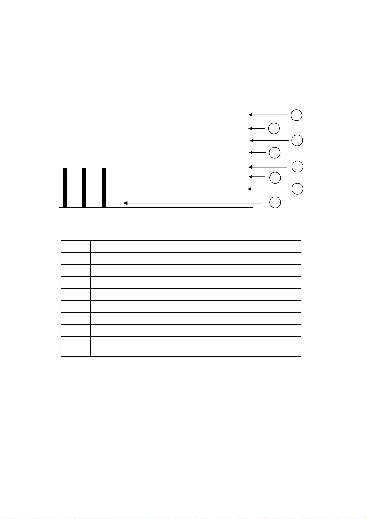
4.5 The Display
Meaning of the display information:
This is just an example and could looks different, depending on the printer setup.
C o u n t. P o w r. ON: 1
I n k C o s t s / J o b :
0.000
M e t e r / S e c o n d : 0 . 0 0 0
X J o b P a g e s / h : 0
No r
6X6 dp i
onl ine
Illustration 4-4: Display indications
Meaning of the display
1 Job Counter, after powering up of o the printer
2 Averaged ink costs of job
3 Current transport speed
1
2
3
4
5
6
7
8
4 Throughput per hour
5 Print resolution measured in dots per inch
6 Rotate print by 180° Nor = Normal, Rev = Reverse
7 Indicates printer mode On or Offline
8 Ink level of each cartridge. Here from Cartridge 1(left bar) to
cartridge 6 (right bar)
4.5.1 Offline Mode
In this type of operation, you can configure the machine via the keyboard.
By using the "ONLINE" key, you access the online condition.
20
Page 24
4.5.2 Online Mode
In this type of operation, you can start the machine via command sequences from
your computer. Printing is carried out in this type of operation.
4.6 Brief Instructions
In order to be able to quickly carry out a test print with no previous experience, you
should follow the operational steps listed in the table below, in the correct order. In
the pages listed in the right hand column, you will find the detailed description of
operational steps.
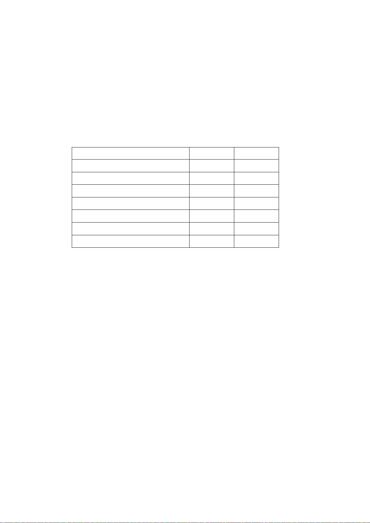
Operational Step Chapter Page
Connect device
Switch on device
Operate device via USB
Set device for media thickness
Set the format of the device
Paper run without printing
Test print
5.1
0
5.2
5.4.1
5.4.2
5.4.3
5.5
22
23
23
36
39
42
42
21
Page 25
5 Start-Up and Operation
5.1 Setting Up and Connecting the Printer
Install the printer as described in chapter 2.3 - “Location of the Printer“.
Power Cord
See Illustration 4-2: PRINTER 830/930 front side on page 17
Caution!
The PRINTER 830/930 is a device of class 1!
The machine may only be operated on electrical circuits with protec-
tive grounding conductors (ground)!
Connect the power cord to the printer. Insert the mains plug into a socket with protective contact.
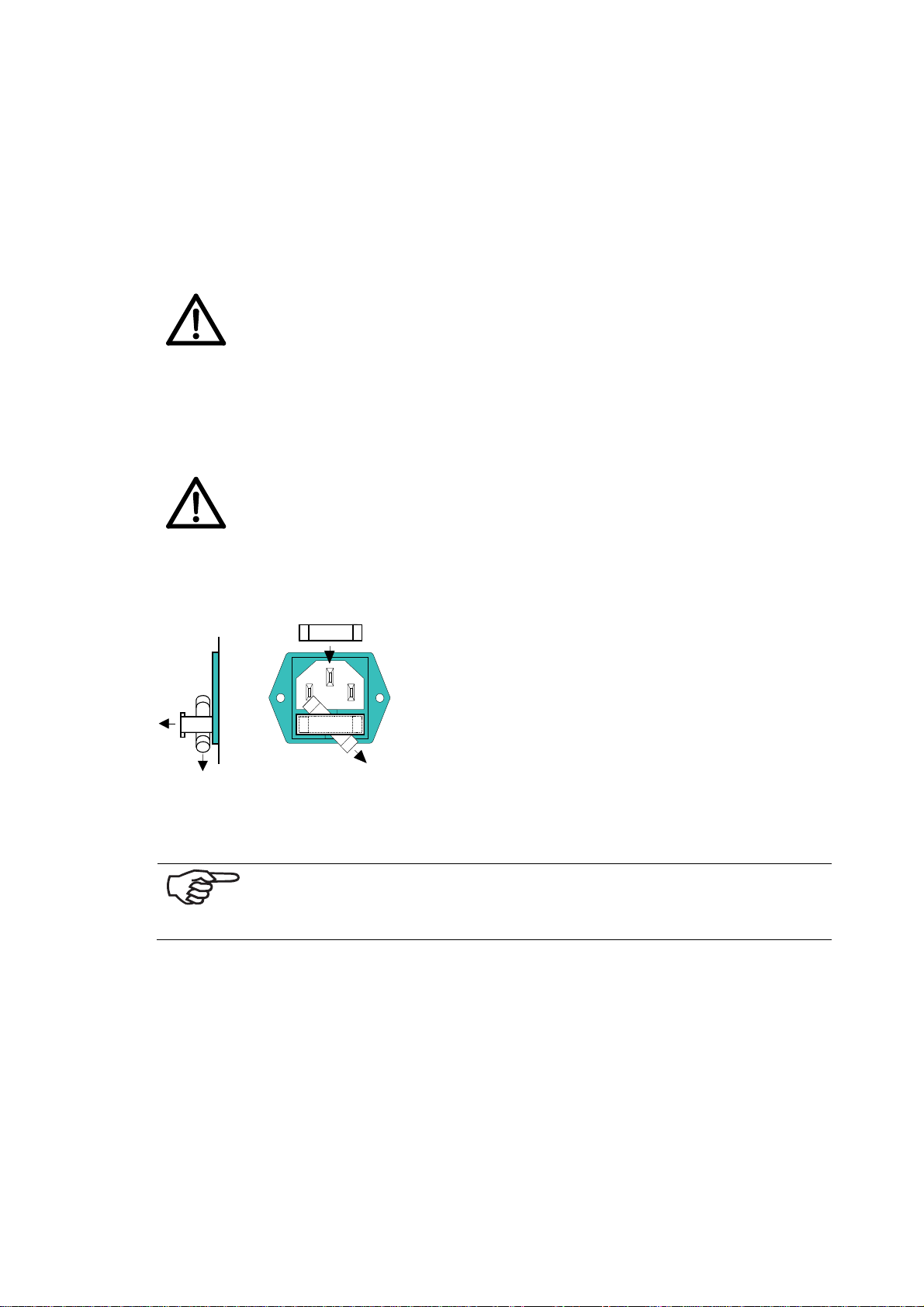
Change the fuses (also necessary when changing the mains voltage)
Caution!
When changing the fuse, you must always remove the power cord
beforehand!
Open the holding compartment with a fingernail or small pen. Change the fuse as
shown in the following illustration.
See chapter
Illustration 5-1: Changing the fuses
Interface Cable
See Illustration 4-2: PRINTER 830/930 front side on page 17
Insert the interface cable into the connector at the back side of the machine (lock
the parallel connector). Connect the cable with your computer.
8.7 - „Technical Data“ – starting on page 89.
If you wish to operate the printer via USB, then read through the
chapter
5.2 “Installing the Driver“ starting on page 23 now.
22
Page 26
Switching on the Printer
Switch the printer on with the ON/Off switch at the back. The following will be displayed on the printer:
Loader 01
Version#1.1.XX#
Starting Application
X.X.XX –PPC
Printer Initialisation
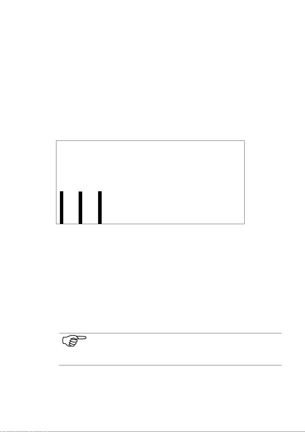
The printer is online with following display:
C o u n t . P w r
On : 1
I n k C o s t s / J o b : 0 . 0 0 0
M e t e r / S e c o n d : 0 . 0 0 0
X J o b P a g e s / h : 0
Carry out paper measurement now?
Pressing OK key = YES, Pressing Cancel key = NO.
During the initial start-up, you have not yet set the printer to your print object. For
this reason, a measurement of length is not yet possible. The length measurement
should be carried out, however, after the setting has been described later.
Press the Online key.
Now the printer is ready for operation:
6X6 dp i
Nor
onl i ne
5.2 Installing the Driver
In order to be able to use the printer’s USB connection, you must first
install the parallel virtual connection on your PC.
In any case you must install the printer driver (see chapter
“Adding a New Printer”)
23
5.2.5
Page 27
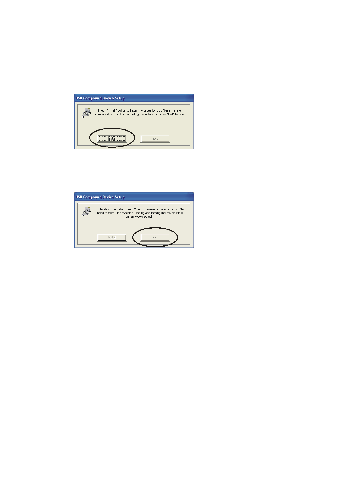
5.2.1 Installation of the parallel virtual connection
1. Call up Setup.exe in the corresponding driver directory.
2. Follow the instructions in the setup window. Press Install to install the driver.
To cancel the installation, press Exit.
Illustration 5-2: USB Compound device setup
3. The installation program now shows the following message:
Installation is in Progress... Please Wait
4. Finally, the following message is displayed:
Illustration 5-3: USB Compound device setup
5. To leave the installation program, press Exit.
6. Connect the USB cable to the printer and to your computer.
7. Windows recognizes the new USB device and automatically begins installing
the driver for the newly connected device.
8. When the Windows desktop is displayed once again, the driver installation is
complete.
24
Page 28
Note:
• When several user accounts will be used on the system, you must mak e cer-
tain that you call up the Setup.exe with Administrator authorization. Ac-
cording to the Windows security model, only the Administrator can install the
driver.
• Windows XP: After calling up the Setup.exe and connecting the printer, a
window is displayed for adding the new hardware. Press Continue, if the
Windows certification dialog box is displayed. Press Complete/Close to
complete the installation.
• When the setup program is run, or when a driver update occurs, confirm the
Windows message that the driver contains no digital signature, with the Con-
tinue button.
• Please, follow the instructions of the operating system, when queried about a
restart.
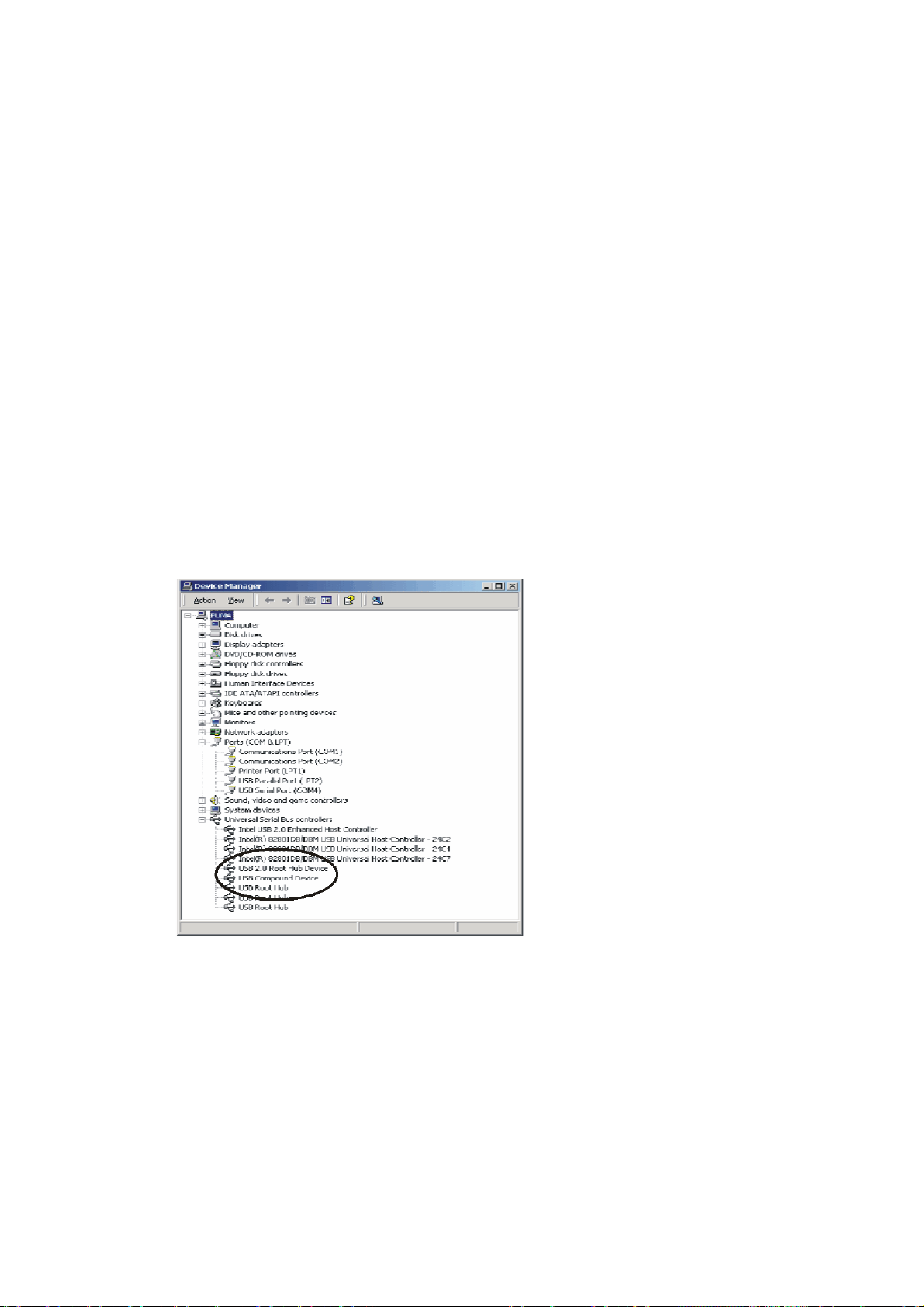
5.2.2 Check the Correct Device Recognition
Right mouse click on the My Computer icon on the desktop
Then > Attributes > Hardware > Device Manager > USB Controllers:
Illustration 5-4: Device Manager
Correct device recognition is indicated by a new entry:
USB Compound Device
25
Page 29
5.2.3 Removal of Already Installed Driver
Sometimes it is necessary or desirable to remove an already installed driver, in order to be able to carry out a new, clean installation. Drivers on the media carriers
could have been damaged. When this has occurred, then the installation cannot be
carried out correctly. Even when the installation procedure has been run without error, it is possible that the driver will not function. In the event that a new driver
needs to be installed, you should first uninstall the old one. The simplest method is
to use the MosUnst.Exe program (found in the directory WINNT\System32 or in
the driver directory). As an alternative, you can remove the driver using the following procedure:
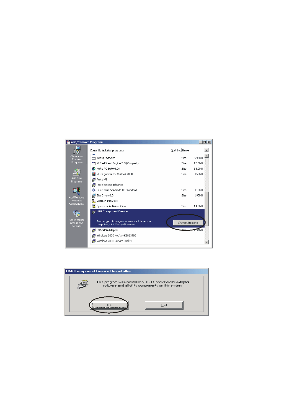
1. Unplug the USB device.
2. Start > Control Panel > Software > Change or Remove Programs.
3. Select USB Compound Device and press Change/Remove.
Illustration 5-5: Remove USB driver
4. In the next popup, press the "OK" button.
Illustration 5-6: Remove USB driver
5. Then press "Restart now/ “Reboot Now“ to restart the system.
26
Page 30
5.2.4 Installation of the Connected Printer
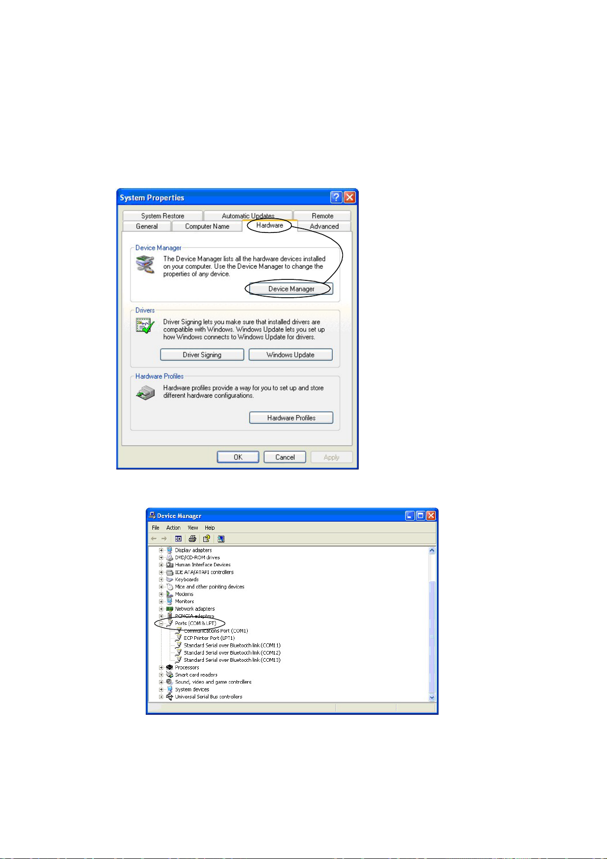
Connect the printer to the computer. A new parallel connection is installed in the
system. You can view the new connection in the Device Manager under connections (COM and LPT). Note the name of the connection.
• Desktop Workstation Right Mouse Button > Attributes > Hardware > Device
Manager
Illustration 5-7: Calling up the Device Manager
Illustration 5-8: Device Manager connection
• The printer is not a Plug & Play device, and it must be connected manually
with the parallel port.
27
Page 31
5.2.5 Adding a New Printer
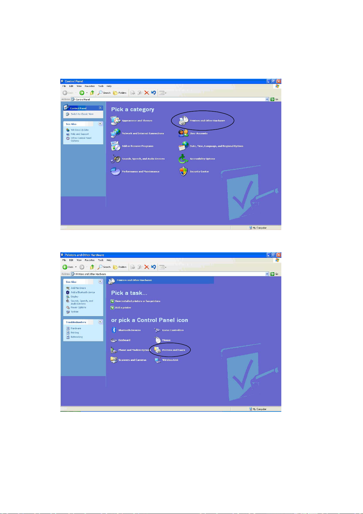
• Click Start > Control Panel > Printer and other hardware
Illustration 5-9: Add printer
• Printer and fax machines
Illustration 5-10: Add printer
28
Page 32
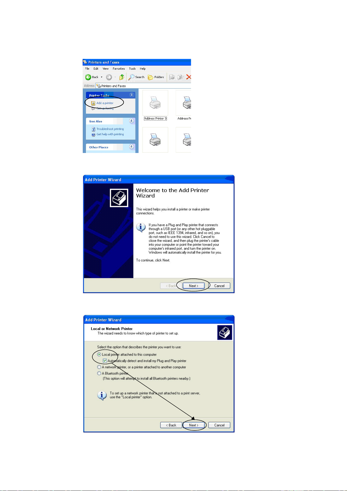
• Double-click on “Add Printer“
Illustration 5-11: Add printer
• Then press Next to resume the procedure with the installation assistant.
Illustration 5-12: Printer installation assistant
Illustration 5-13: Printer installation assistant
29
Page 33
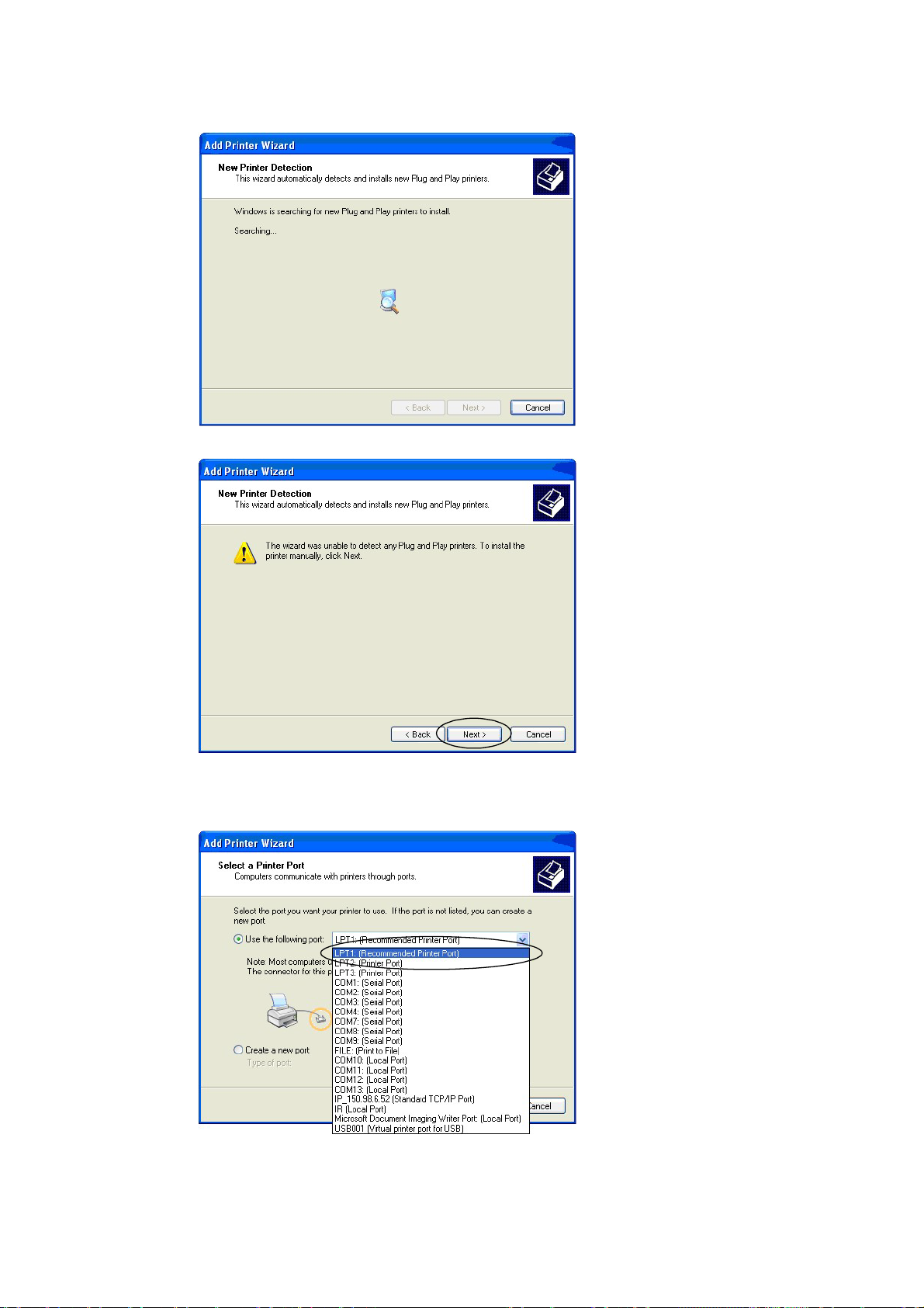
Illustration 5-14: Printer installation assistant
Illustration 5-15: Printer installation assistant
1. Connect the printer with the connection that was newly added with the USB
driver. (Hardware > Device Manager)
Illustration 5-16: Printer installation assistant
30
Page 34
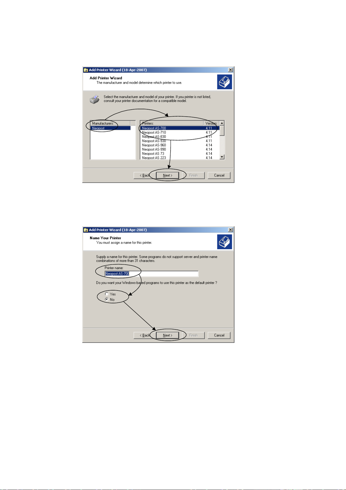
• Then select the printer according to manufacturer and type. When necessary,
use the driver CD.
Illustration 5-17: Printer installation assistant
• Select your preferred printer:
• Select the printer name.
Illustration 5-18: Printer installation assistant
• When needed, a test page can be printed.
• Press Finish in order to complete the printer installation.
31
Page 35
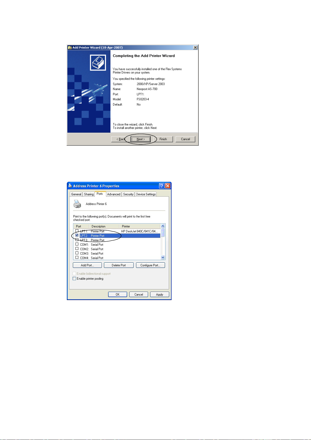
Illustration 5-19: Printer installation assistant
• You can check the correct connection of the printer in the settings for the
printer:
Illustration 5-20: Check printer installation
5.3 Inserting the Ink Cartridge
The print is made with a commercially available ink cartridge. Aft er the in k has
been used up, the ink cartridge should be replaced.
The PRINTER 830/930 is equipped with an ink cartridge. Ink cartridges of the following types may be used:
• Standard Black
• Versatile Black
• Fast Dry Black
32
Page 36
• Spot Colour Blue
• Spot Colour Red
• Spot Colour Green
Be aware of the notes in chapter
as well as the notes of the ink cartridge manufacturer.
2.2, page 13: „Handling Ink Cartridges“
5.3.1 Correctly Inserting the Ink Cartridge
First, you must have access to the cartridge holder.
In the event that the printing unit is found on the front sidewall, unscrew the thumb
screw on the printing unit and push the printing unit into the middle.
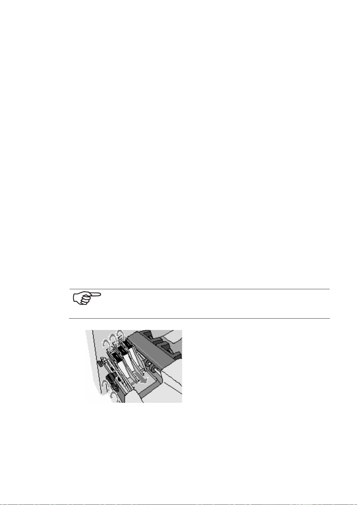
1. Lift completely all locking levers (upward).
2. Take the ink cartridge out of the packaging and remove the protective strip.
Do not touch the contact plate…
In order to ensure a secure contact for the ink cartridge to the electronics of
the printer, the locking lever has two functions:
• Tipping the ink cartridge into the end position
• Secure locking during operation
3. Set the ink cartridge, with the jet surface downward, with a straight motion
into the holder – do not press in the direction of the locking lever – .
The ink cartridge stands at a slight slant, prior to the closing of th e locking
lever. The locking lever then tips the ink cartridge int o the end position.
4. Close the locking lever.
Do not tip the ink cartridge into the end position by hand! This
is taken care of by the locking lever. Otherwise, you can damage the ink cartridge or the contact plate!
Illustration 5-21: Open locking lever
33
Page 37
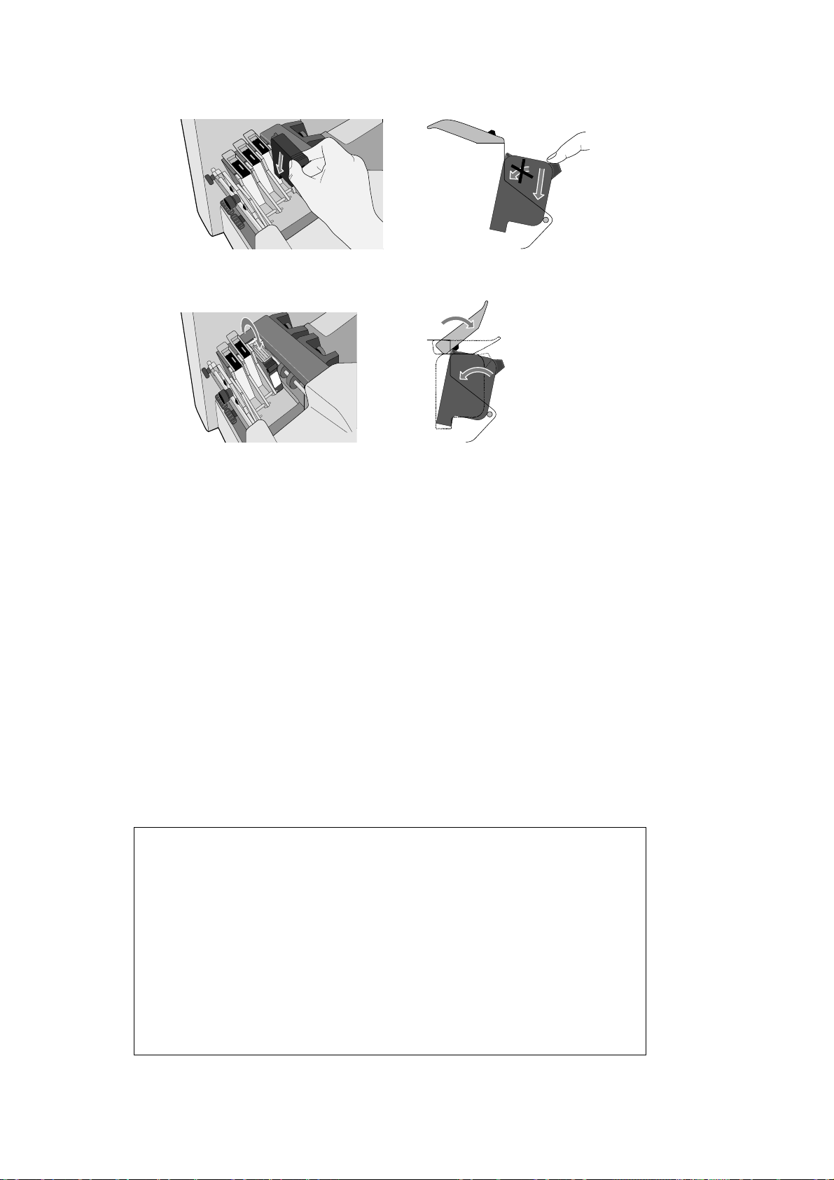
Illustration 5-22: Inserting the ink cartridge
Illustration 5-23: Close locking lever
5.3.2 Resetting the Ink Counter
If you are online, change to offline mode with the Offline butto n.
Press the Home button.
Change to the Printer Configuration menu and confirm with the Arrow Right
button.
Change to the Ink menu, confirm with the Arrow Right button and here, select
the Cartridge Reset menu and confirm again.
Now you have the option to either reset all cartridges as a whole or to selectively
reset only individual cartridges.
If you want to reset all cartridges, move to the All Cartridges fi el d with the Arrow
Up or Arrow Down button. Confirm with OK.
If you want to reset particular cartridges only, move to the corresponding cartridge
field with the Arrow Up or Arrow Down button and confirm. To leave this menu,
press the Cancel button; thus you reach the next higher menu.
5.3.3 Display for the Change of Ink Cartridge
C o u n t . P w r
On : 1
I n k C o s t s / J o b : 0 . 0 0 0
M e t e r / S e c o n d : 0 . 0 0 0
X J o b P a g e s / h : 0
6X6 dp i
Nor
off l ine
34
Page 38
If less than 5% ink is in the cartridge the ink level bars are not displayed and you
get an error message:
NO INK !!
CHANGE PRINTHEAD
In the menu “Error Level” you can select:
STOP: Printer should stop if “No Ink” is displayed
IGNORE: Printer should print if “No Ink” is displayed
5.3.4 Set the ink Counter
The calibration is carried out in offline mode. Press the Arrow Down or Arrow Up
button and confirm “Offline” with the Arrow Left button.
C o u n t . P w r
On : 1
I n k C o s t s / J o b : 0 . 0 0 0
M e t e r / S e c o n d : 0 . 0 0 0
X J o b P a g e s / h : 0
6X6 d p i
C1:97%
offline
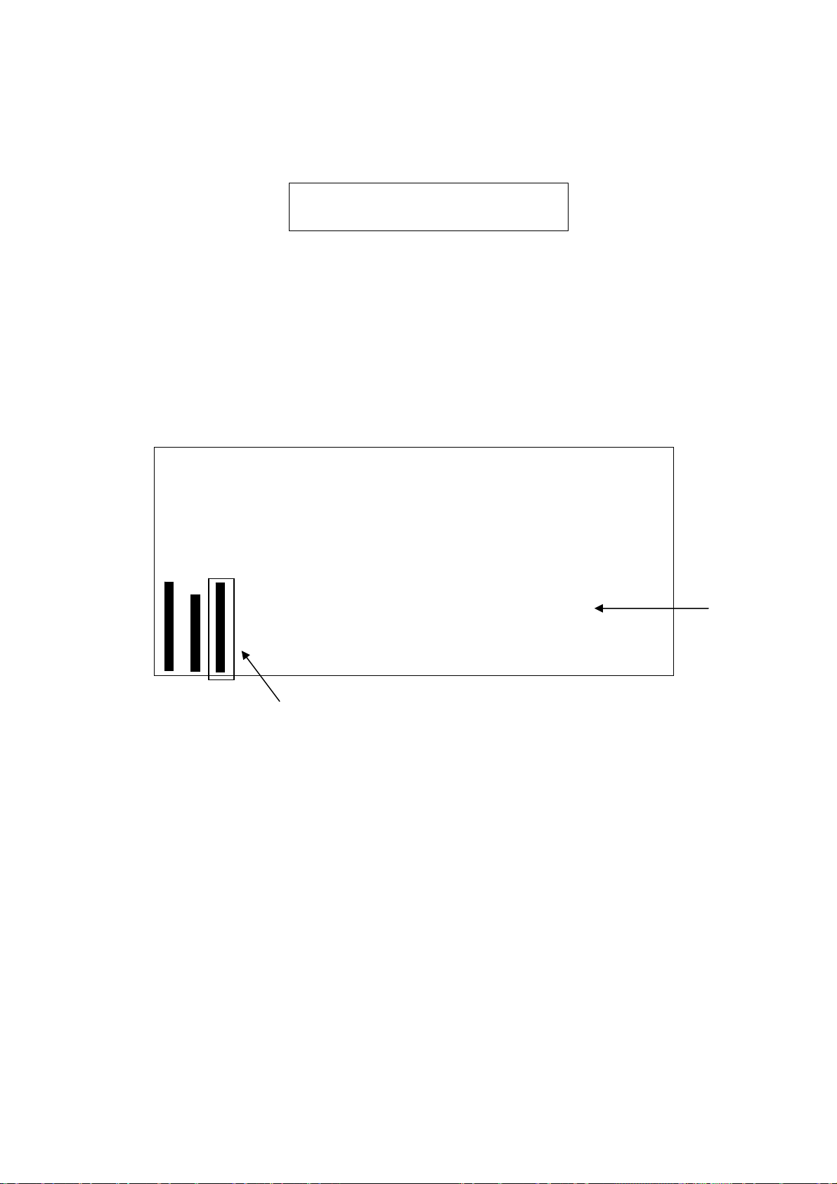
The display will show the following:
The right ink-level bar gets a frame around that you can check which cartridge you
want to change.
Here it is cartridge 1 from unit 2 and the ink level is 97%.
To change the level, press the Arrow Down or Arrow Up button.
To change to another cartridge, press the Arrow Left button.
With this menu you are able to change each level from each cartridge very fast.
For comparison, the ink level display of an ink cartridge HP 51645A is on the back
side.
35
Page 39
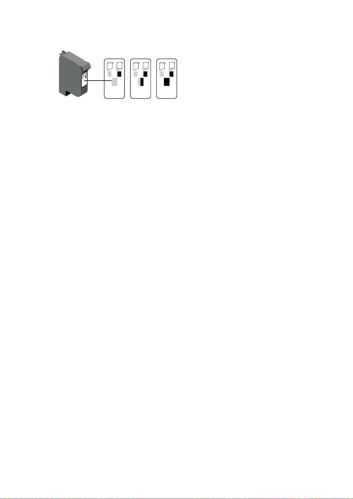
Illustration 5-24: Ink supply display
For replacing the cartridge, switch the printer offline using the start key (Off must
be indicated on the display). Carry out a “CARTRIDGE RESET“ in the menu.
5.3.5 Cleaning the Ink Jets
For time to time, the ink jets need to be cleaned or unclogged.
1. Insert a single sheet of paper into the feeder.
2. Switch the PRINTER 830/930 into the Offline mode.
3. At the same time, activate the Quick and Arrow down keys.
The ink jets are then sprayed onto the fed sheet of paper, in order to unclog themselves.
5.4 Print job Setup
So that a correct and sharp print appears on an exact position on the print object,
the printer has to be set for each print object. The printer processes various widths
(up to 6 mm) and various formats (from postcard size to B4 format, with special
accessories up to format C3). This is why it is necessary to implement settings for
the widths and format. For this work process, keep ready the next print object that
you would like to print.
5.4.1 Setting Media Widths for the Machine
5.4.1.1 Setting the Printing Unit to the Media Width
For a sharp print, it is important to set the height of the printing unit over the print
object. This is only possible with a loosened printer-unit carriage:
36
Page 40
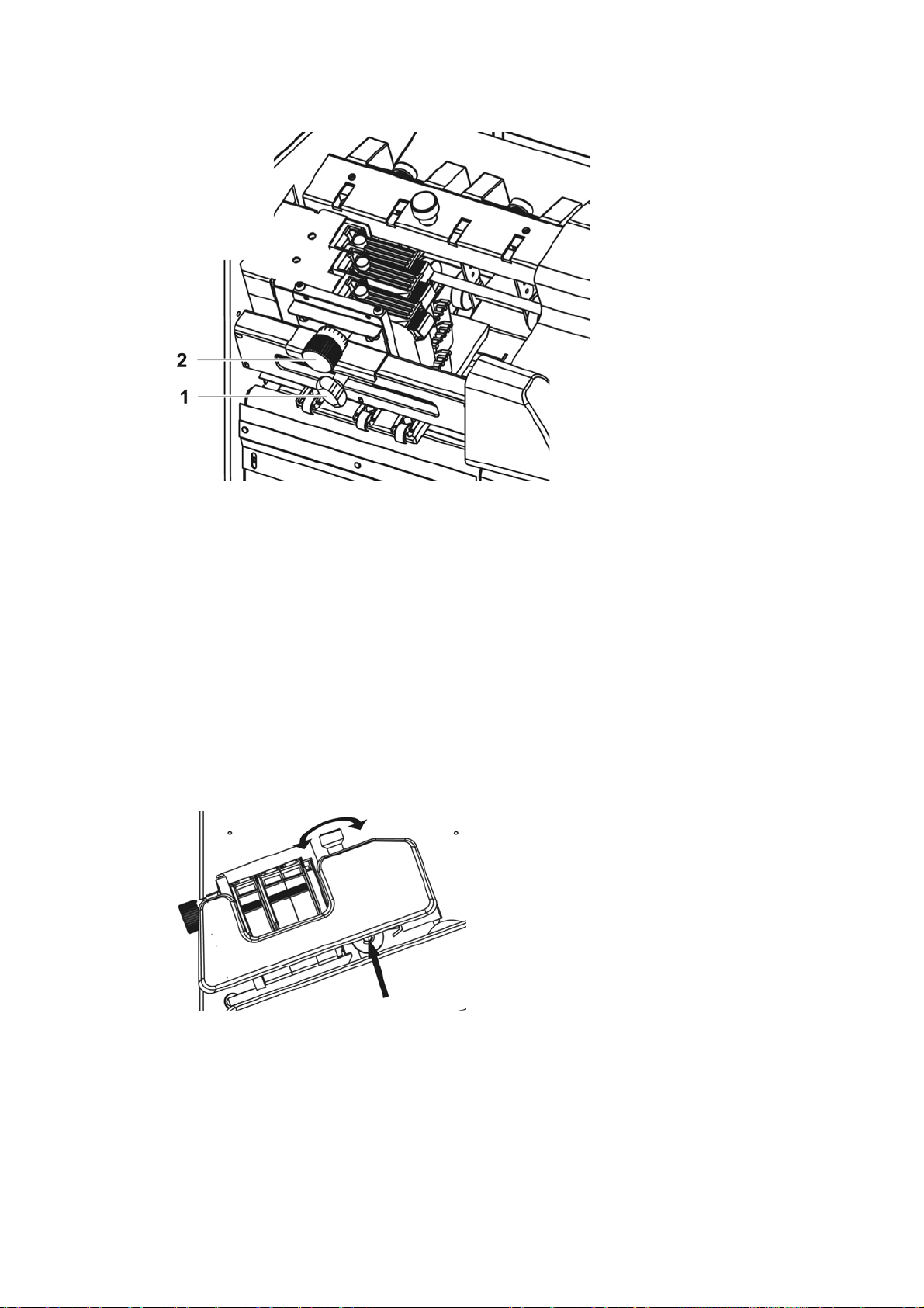
Illustration 5-25: Set printer
1. To do this, loosen the thumb screws (1) of the printing unit.
2. Use the scale button (2) to set the width of the print object. The button has a
millimetre scale.
3. Screw the thumb screw of the printing unit in tightly.
5.4.1.2 Setting the Media Width for the Sheet Separating System
Height adjustment of the pickup rollers
Up to a print object width from 1.5 mm to 2 mm, the rollers can remain in the lowest position. With a thicker print object, the distance should be set, so that the print
object is subject to the appropriate printing pressure on the rollers. This can be
easily tested with the insertion of the print object. The press rollers lift up on millimetre per revolution.
Illustration 5-26: Height adjustment of the pickup rollers
Setting the Height of both sheet separators
In order that only one print object is fed in, both separators are to be set for the
print object.
37
Page 41
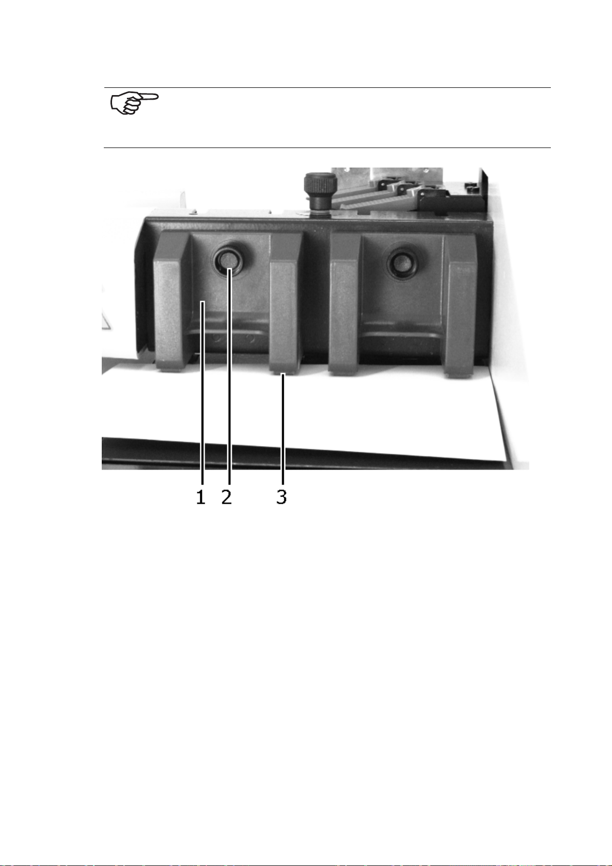
Both sheet separators must always be set, even when – for example –
a small format print object only lies on one separator. When this is not
done, the free separator may drag on the transport rollers. This leads
to increased wear on the transport rollers; entry may cause damage.
Illustration 5-27: Setting the separating finger
1. Loosen the knurled screws (2) of both separators.
2. Lift up both separators (1) and lay the print object under the separating finger (3). With narrow print objects, it may be the case that only two inner
separating fingers reach the print object, e.g. postcards, DL envelopes, No.
10 envelopes. In this case, lift the outer separator (1) up to the upper stop
and clamp it fast.
This step is also recommended, when narrow print objects are partially
reached by a separating finger, e.g. with C6 and DL envelopes.
When only three separating fingers reach the print object, then an additional
print object is to be placed under the fourth separating finger. (It may be possible here, that you have to remove the outer side guide)
38
Page 42
Failure to comply with these steps can lead to premature wear on the
separation rollers.
3. Allow both separators (1), without exerting pressure, to fall upon the print
object and again fix the knurled screws (2) in position.
5.4.2 Setting the Print Format
5.4.2.1 Setting the Print Position of the Address
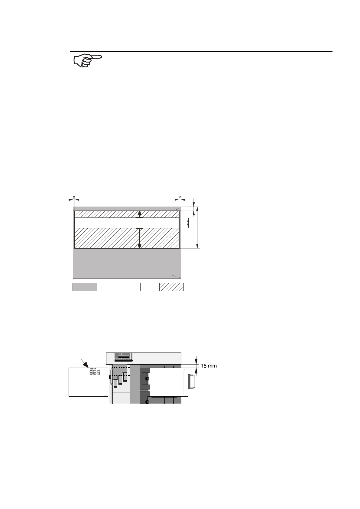
Before setting the desired address position, you must know in which area printing is
possible.
The positioning of the address height is carried out by moving the printing unit. The
printable area results from the necessary margins and the traverse path of the
printing unit:
X+Y = 2 mm (0,078“)
TestprintRENA613 SL
Test Tes t Te st
Test Tes t Te st
Test Tes t Te st
Test Tes t Te st
Test Tes t Te st
Test Tes t Te st
Test Tes t Te st
Test Tes t Te st
38
15
(1,5)
145
(0,6)
(5,7)
Not printable Print area Printing unit traverse area
Illustration
5-28: Setting the print position for the address
The upper margin depicted here of 15 mm can be reduced to 0 mm, when required.
To do this, push the rear side guide onto the red marking. Now printing can be carried out without margins.
Illustration 5-29: Setting the print position for the address
The printing direction depends upon the size of your print object and the upper
margin. When the desired margin space is not reachable for the printing unit, then
the address block and thereby the print object must be rotated by 180°.
39
Page 43

5.4.2.2 Positioning the Address in Height
The PRINTER 830/930 is a WYSIWYG printer
1
with limitations. The limitations lie
in the vertical position of the address. Heeding the following note is important for
your document:
1. In your page layout, set your document to the portrait format.
2. As a rule, enter the value 0 for the upper margin.
3. The last position in the print is set through the mechanical positioning of the
printing unit:
4. Lay the print object in the printer.
5. Loosen the knurled screw on carriage of the printing unit.
6. Move the printing unit, so that the jet surfaces of the ink cartridge lie at the
desired position. If the desired distance from the edge is not reachable for the
jet surfaces, then turn the print object around 180°. Now position the jet surface for this situation.
7. Fix the carriage again in position.
8. If you have placed the print object in at 180°, then the print must also be set
at 180° (Rev):
9. In the event that the printer is in the offline mode, press the Offline key and
switch the printer to OFFLINE.
10. Press the Quick key, navigate with the Arrow up key to the “Orientation”
Menu and confirm with OK. Now you can change the print direction from
Normal to Reverse (Rev).
5.4.2.3 Positioning the Address in Width
The positioning in width is determined via the software on the PC:
• Position the address as desired, for example with the help of the left margin
setting, with the tabulator, or other suitable formatting.
So that the positioning, as entered into the program, can be carried out correctly on the print object, the printer must recognize the exact length of the
print object. This is determined in a length measurement.
5.4.2.4 Setting the Directional Control
5.4.2.4.1 Setting the Side Guide
First, you must know whether the print object runs lengthwise or widthwise through
the printer.
The lines are always printed in the direction the print object is run.
If the lines run parallel to the longer side, the intake occurs using the narrow side.
1
WYSIWYG (What You See Is What You Get)
40
Page 44
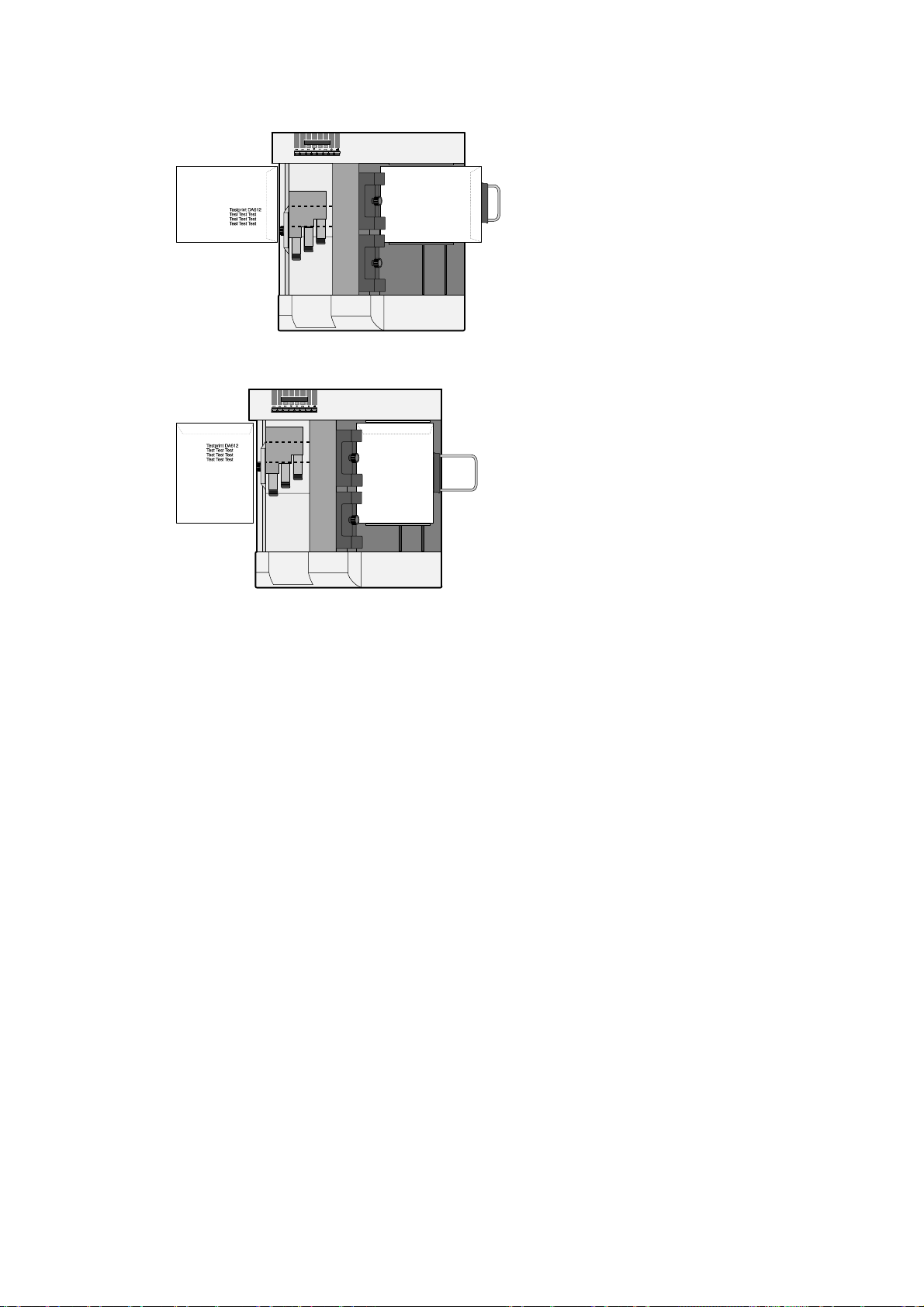
Illustration 5-30: Setting the print object format
If the lines run parallel to the shorter side, the int a ke occurs using the longer side.
Illustration 5-31: Setting the print object format
1. Push the rear side guide completely to the side wall of the machine.
2. Lay the print object between the side guides. Guide it toward the separator.
3. Push the frontal side guide up to the print object. The print object must not
be jammed. With very narrow formats, the outer side guide may have to be
turned.
When the print object is larger than can be reached by both delivered side guides –
as an alternative to the frontal side guide – a middle and a longer side guides (see
page 88 – “Accessories“) are available.
Which side guide should be used for various formats can be selected from the overview table of the parameter PAPER SIZE on page 50 and from chapter
Guide“ in Appendix.
5.4.2.5 Setting the paper Support Plate
1. Lay a single print object in the feeder.
2. Position the bracket in the middle, between both side guides.
3. Push the plastic part (tray support) on the guide bracket so far up to the print
object, that it just touches it.
4. Fan the print-object stack, so that the lowermost sheet can be fed in first,
and place it on the guide bracket.
5. Push the plastic horizontal strut of the guide bracket completely to the print
object. The lowermost print object should be just touching the horizontal
strut.
8.5 “Side
41
Page 45
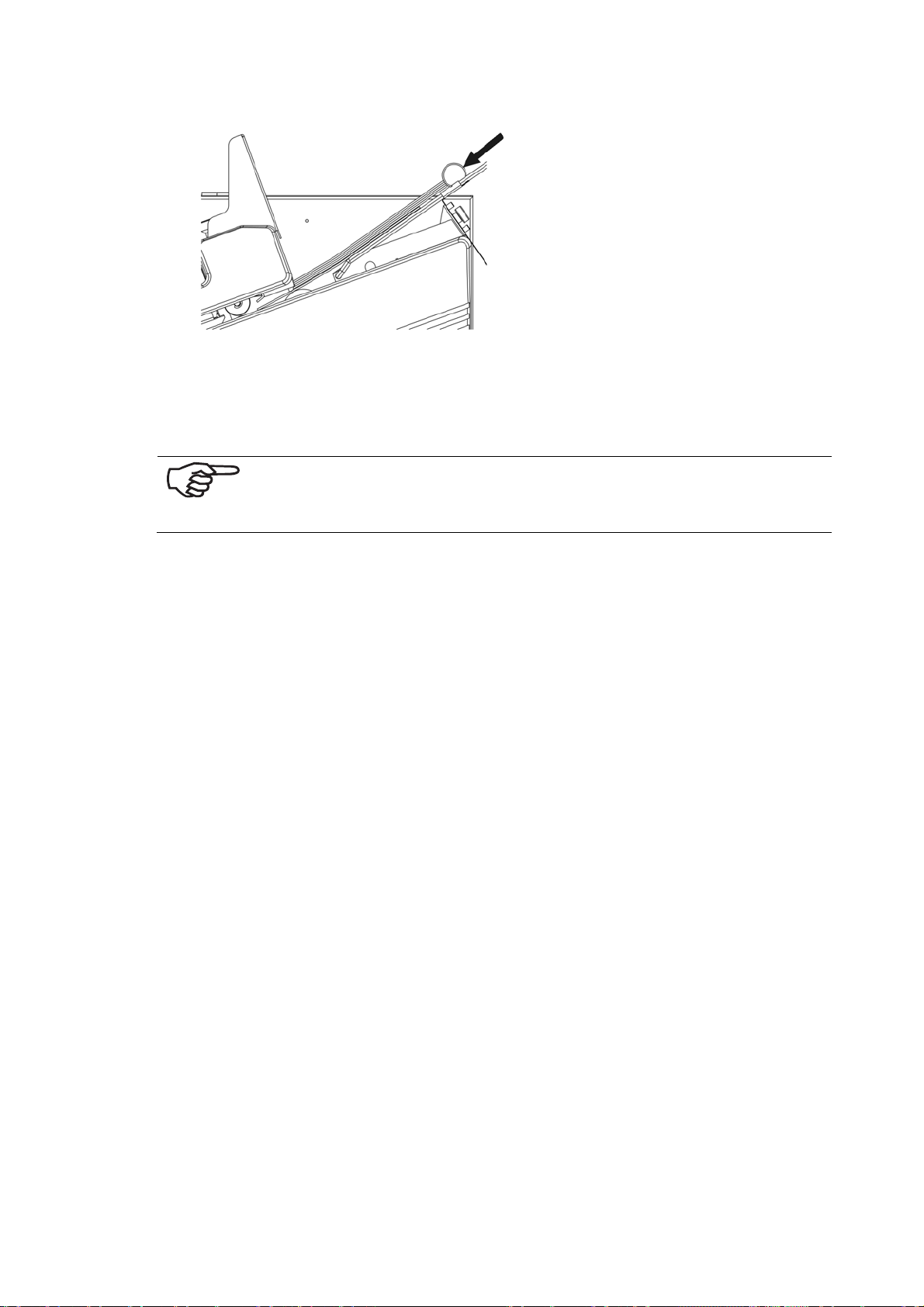
Illustration 5-32: Setting the guide bracket
6. Now test the trouble-free feeding of the print object. To do this, allow a stack
of the print object to run through with the help of the paper transport in the
Offline mode as follows:
Caution! When doing this, do not put your hands inside the machine when it is in operation.
7. In the event that the printer is not in the offline mode, activate the start key
and switch the printer to Off.
8. Press the pap key, and the print object will be transported or ejected. By
pressing the pap key again, the paper transport ends once again.
5.4.3 Checking the Paper Transport
Length measurement
Carry out the length measurement of the medium to be processed by pressing the
QUICK + ARROW LEFT keys.
Check the displayed value as compared to the actual value. When there is a variance between the two values (more than 3 mm), a wrongly set paper feed could be
the cause. When the software transmits the wrong paper length value, the paper
length measurement can be locally locked in the machine. Pressing longer on the
key for paper measurement makes possible the local locking of the paper length
(visible on the display with an ”(L)“).
Transporting of a single medium
• When you press the Quick + Arrow Right keys, the medium found in the
feeder is fed in, transported under the printing unit, and then ejected.
When you press the Cancel key again, the paper transport is stopped. It can also
be halted by pressing the OK key.
5.5 Test Print
1. Switch on the PRINTER 830/930 using the ON/OFF switch and wait until the
start-up routine has been completed.
2. Change from the Online mode to the Offline mode by using the Offline
key.
42
Page 46
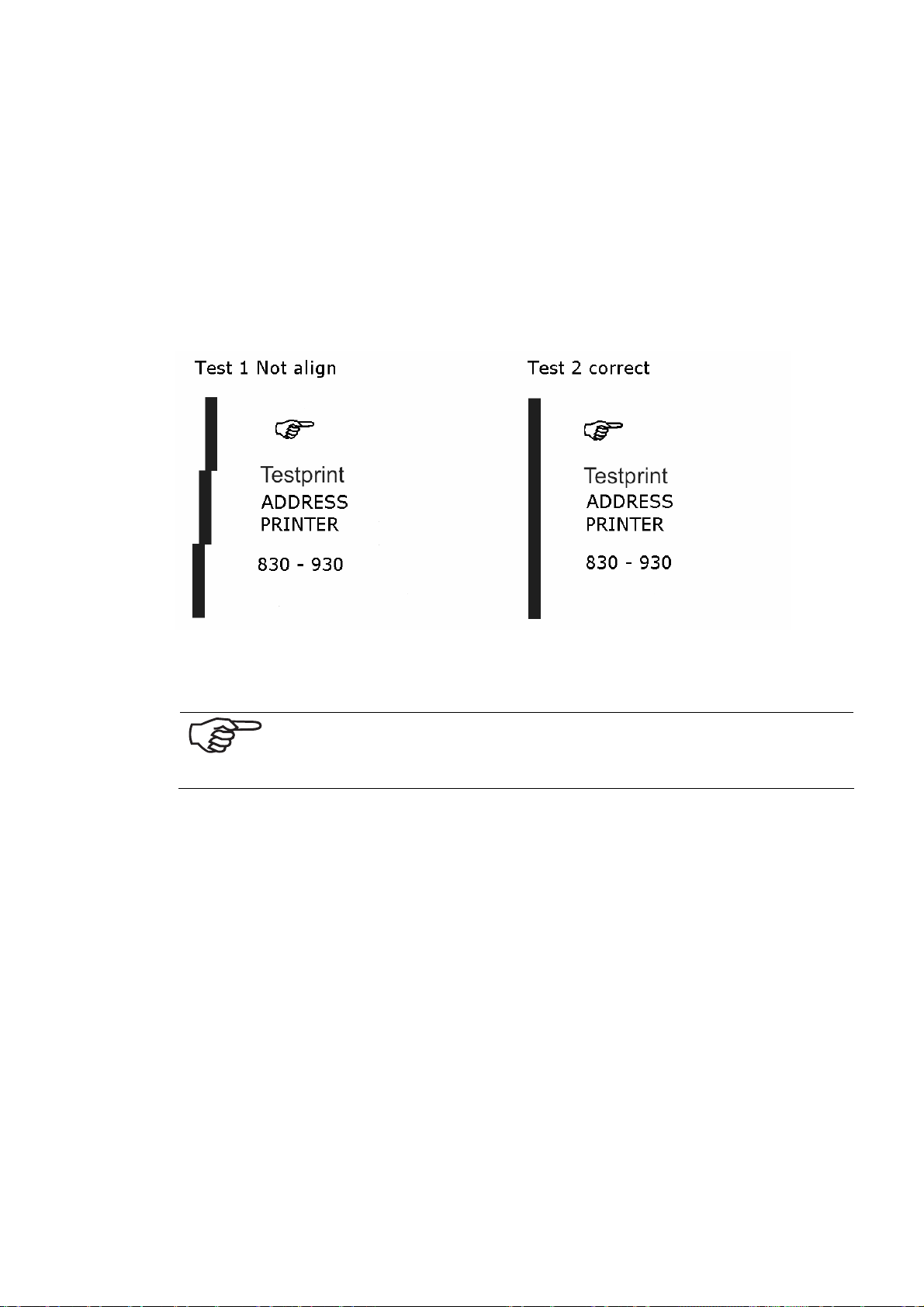
Printing the Test Picture
1. Place as many media in the feeder as you would like to use for a test print,
e.g. 1 medium.
2. Confirm with the Quick +Arrow Up keys. The test print is carried out. Press
the key again, in order to stop the procedure.
3. Using the test print, check the position, the orientation and the quality of the
print on the medium.
Possible printout errors:
Test picture 1 with errors Test picture 2 correct
Illustration 5-33: Setting the dosing roll
There is too much pressure from the separating finger on the print object
Never put your hands inside the machine when it is in operation!
5.6 Machine Counters
Three different Counters are installed in this machine:
5.6.1 Day Counter
Each printout after the paper is ejected is counted and the value is readable in the
right upper area.
This counter includes the “Job” and the “Service” printouts.
After powered off and on the machine, the counter is reset.
5.6.2 Service Counter
A test page count contains the number of Test prints with the accompanying paper
ejection.
This count is carried out with the activation of the "TEST" key or several “Service”
printouts, with the machine in the offline condition.
43
Page 47
5.6.3 Counting of Job Pages
A job page count contains the number of data printouts received by the computer
with the accompanying paper ejection.
This count is carried out with the machine in the online condition.
When you continue data transmission with printouts, counting is resumed.
All counters are reset when the machine is switched off!
To change the view of the 3 counters you have to be in the Offline
mode. Select and confirm your selection with the arrow up or down
button and then change it with arrow left or right button.
44
Page 48

6 The Programming Mode
6.1 Purpose of the Programming Mode
The programming mode is used for setting manually a number of parameters via
the control panel. Parameters are definitions of set point values for font settings,
print quality, papers settings, as well as special and test funct ion s.
Since the printer is operated, as a general rule, from a text or address processing
program, the factory settings have been optimized for this, and normally no
changes are necessary.
In individual cases, however, adjusting the parameters may be required. In such a
case and should you wish to make full use of your address printer’s capabilities, all
of the parameters are discussed in this chapter.
This chapter is intended as a reference source for experienced users.
6.2 The Control Panel in the Programming – Offline- Mode
Change to the programming mode:
1. Press the Offline key
2. The blue LED has to be on and the display shows OFFLINE.
45
Page 49
6.3 Keyboard Layout in the Programming Mode
Illustration 6-1: Keyboard layout for the programming mode
In online mode, the printer can only be switched to offline mode by pressing the „Offline“ button.
Quick Button
The Quick button can only be used in offline mode.
Function when singly applied:
By pressing the Quick button, the quick menu can be directly called up at any time;
this serves for speedy operation.
By pressing the OK button the selected menu function is executed.
By using the navigation buttons Arrow Up and Arrow Down, n a vigation
within the quick menu is possible.
When first pressing the Quick button and then together with another button the
secondary function of that button is called up. (Like the Shift button on the PC).
• Quick – Arrow Up = Test print
Based on the current settings, a test print is executed. If the combination function
is called up from a menu item, then you return to this item after leaving the test
print. If the button is pressed briefly, a test print is carried out – similar to the pap
button - and afterwards you return to the called-up display again. If you press the
button for a longer time, a continuous test print is carried out. With Cancel you
break up the continuous test print and return to the previous display again.
• Quick – Arrow Down = Clean Heads
A sheet is supplied and a line pattern is printed onto it, based on th e currently ad-
justed paper length.
46
Page 50

• Quick – Arrow Left = Run Paper (Supply Paper)
If you press the button shortly, only one sheet is transported; afterwards you return to the previous display. If you press the button for a prolonged time, a continuous paper run is started. By pressing Cancel you break up the run, and you return to the previous display.
• Quick – Arrow Right = Paper Length (Measure paper length)
Using this combination you may measure the paper length. Subsequently, the
measured length is displayed. If you hold this combination pressed for a longer
time, the measured length is locked and therefore prevented from being overwritten by the software.
47
Page 51

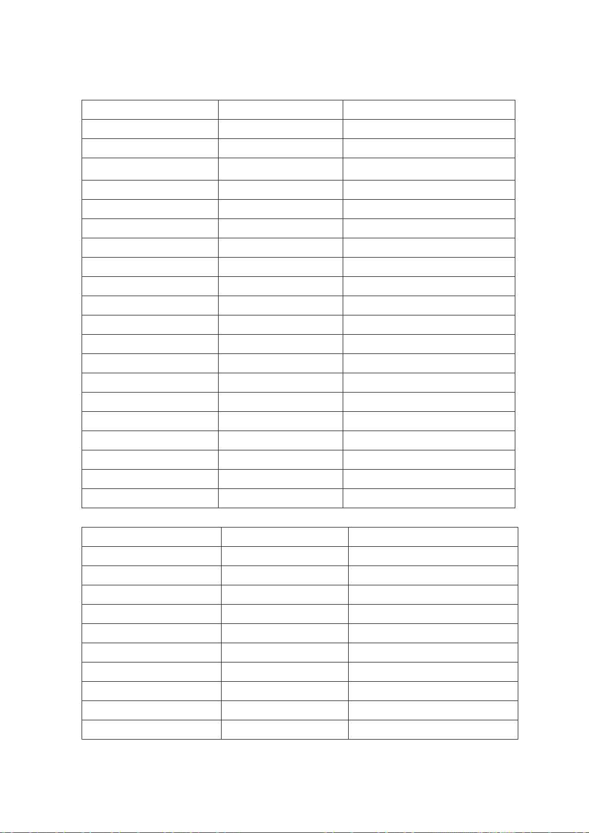
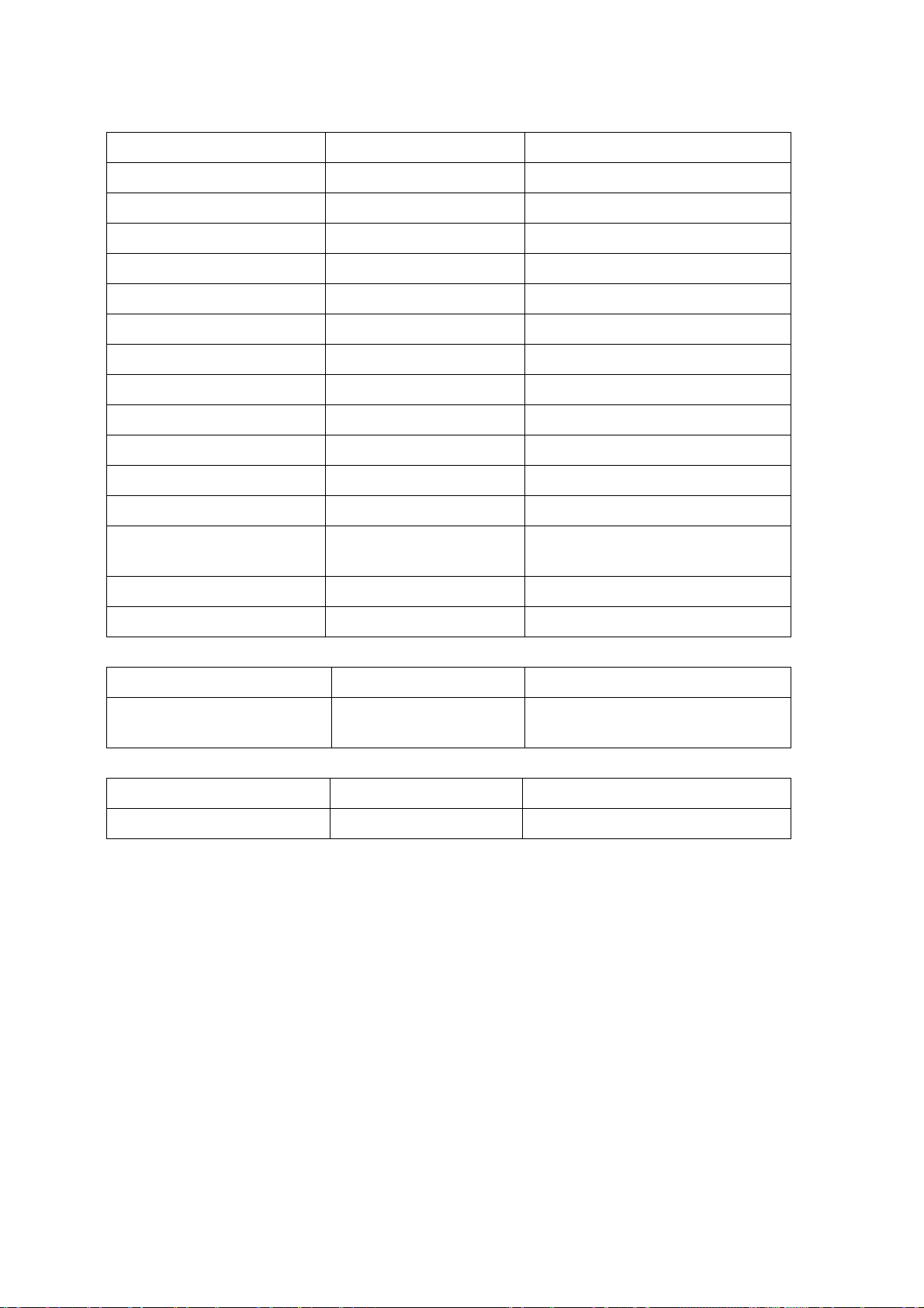
6.4 Menu Overview
If the printer is Offline, press the HOME-k e y and the display will show the main
menu from the printer. With the Arrow up and Arrow down keys you can navigate through this menu. With the OK or Arrow right you are able to
confirm the submenu.
Home
Printer Config
Job Config
Service
Language
Settings
Main menu Submenu Options
Printer Configuration Maintenance Auto Clean Heads
Capping Delay
Adjustment Steps Correction Patt.
Corr. Dist. U1 – U2
Corr. Dist. U2 – U3
Corr. Dist. U3 – U4
Corr. Cart. 1 – 2 UX (X = 1, 2,
Boot Defaults Unit of Measurement
Ink Cartridge Optimizing
Warming
Prewarming
Ink Cost. Config
3, 4)
Corr. Cart. 2 – 3 UX (X = 1, 2,
3, 4)
Error Handling Error Level Font
Empty Cartridge
Beeper
48
Page 52
Main menu Submenu Options
Job Parameter Quality 6x6D, 6x3D, 3x6D, 3x3D,
2x6D, 2x3D, 1x6D, 1x3D
Transport Param. Paper Speed
Auto. Pap. Speed
Paper Time Out
Layout Orientation
Paper Size
Left Margin (mm)
Offs. Edge (mm)
Font Parameter Font
Character Spacing
Character Set
Typ of Barcode Zip, bpo4, Kix,2/5i, EAN,
Codabar, Code 39,128,
Code 93, AUS4state,
Canada, Off
Paper Sensor Off, On
Dos Mode Linemode
HEX to ASCII
Auto. LF
Main menu Submenu Options
Service Test Pattern Nr1, Nr2
Hardware Test Display
Key Test
Ram Test
Ram Test Contin.
NV-Ram Test Cont.
Speed Measurement
Paper Sensor
Alignment Horiz.
Alignment Vertic.
49
Page 53
Correction Pattern
Cart. Print Pattern
Check Cartridges
LED/ Beeper
Configuration Info Firmware: (X.X.XX)
SerNr.: (XXXXXXXXXXX)
Page Cnt.: (XXXX)
RAM: (64 MB)
Hardware: (V16-0)
DC: (x A)
Printing Setting
Printing Input Dump
Print Character Set
Main menu Submenu Options
Language
Main menu Submenu Options
Settings Nr 0 – Nr 9
Dump
Englisch, Deutsch
Franz., Ital., Esp
6.5 Explanation of the Individual Menus
Printer Configuration
Settings affect the printer.
Job Configuration
Settings affect the print job.
Service
Test routine for checking the hardware.
50
Page 54
Language
Different languages can be selected.
Settings
Selection of a configuration.
Printer Configuration
Maintenance
Auto Clean Heads
Off
is the factory setting. In the setting „1st“, prior to each print job, a page with a
black bar is printed to purge the cartridges.
Auto Prime
off = no cleaning of the jets before printing or by means of a test print
on = Jets are cleaned before printing, when no paper lies beneath the light barrier
Adjustment Steps
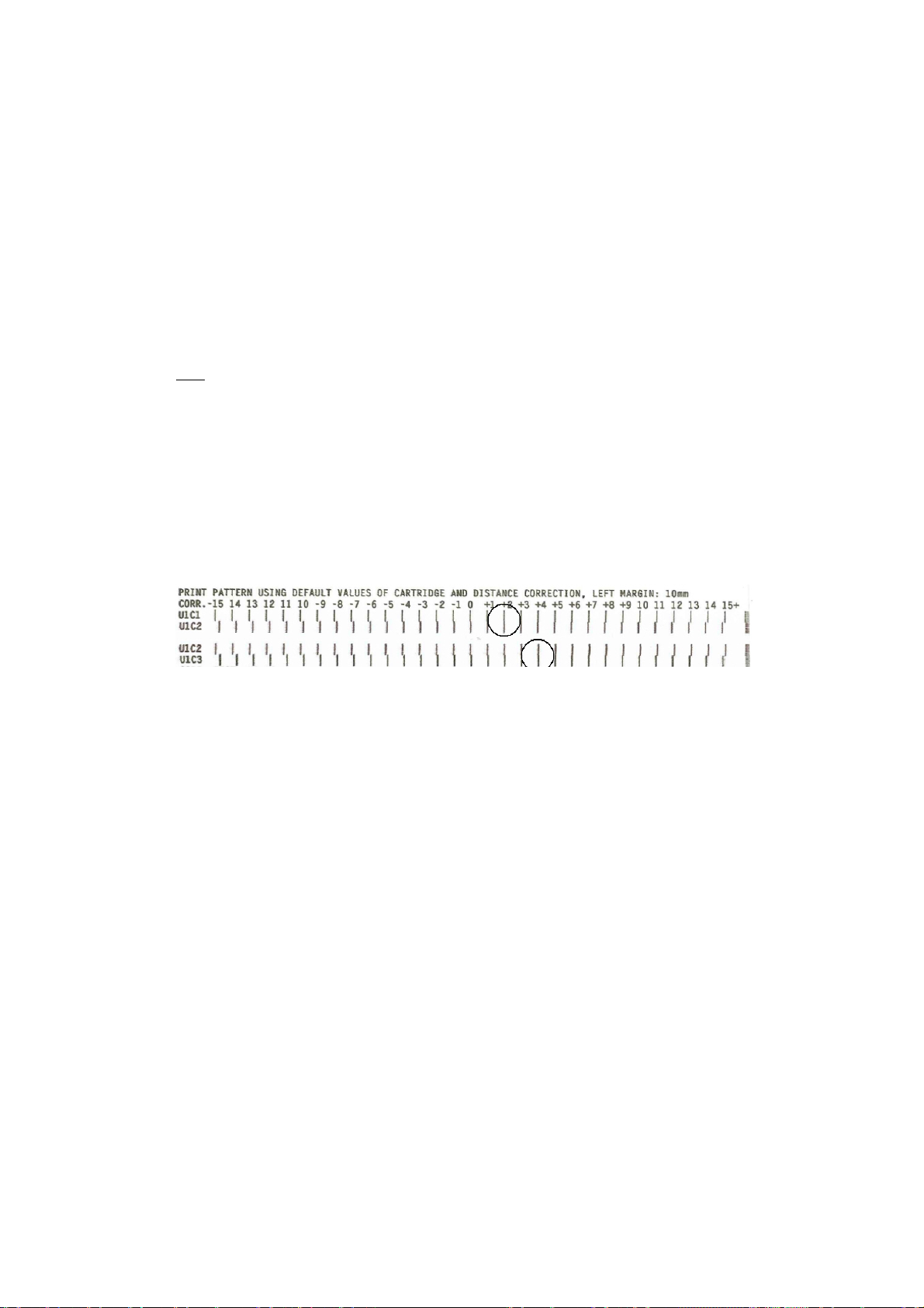
Correction Pattern = Test print to detect which value is the correct one for each
cartridge.
This kind of calibration may become necessary since a completely tolerance-free
production of a print unit is not possible. Slight deviations due to manufacturing
tolerances can be balanced via the software of the control device.
Calibration can only be carried out at the installed device and can therefore not be
performed by the manufacturer.
Press the „Quick“ and „test“ buttons simultaneously and place paper onto the band.
The printer will carry out a test print with the cartridges in the particular print
heads.
Corr. Dist. U1-U2
This serves the adjustment of production tolerances between printheads.
The resulting misalignment of the ink jet surfaces of two neighbouring cartridges
can be balanced horizontally.
Corr. Dist. C1-C2 is for cartridges 1 + 2
Corr. Dist. C2-C3 is for cartridges 2 + 3
Boot Defaults
Unit of Measurement
Millimeter, Zoll (Feet/Min)
Choices of speed and length values for the graphic account on the display.
51
Page 55

Ink
Cartridge Optimizing
Optimizing the cartridge temperature (TTOE)
• Selection possibilities:
all: all three cartridges are optimized
Crt1: only cartridge 1 is optimized
Crt2: only cartridge 2 is optimized
Crt3: only cartridge 3 is optimized
no: no action is carried out
Check: Testing and display of the condition for each cartridge
For the optimization, no paper may lie underneath the cartridges. The printing units
must be positioned in a set area.
For this reason, the query is displayed:
Paper Removed
OK=YES Cancel=No
After pressing the Enter key, the second query is displayed:
Print units Centered?
OK=YES Cancel=No
After pressing the Enter key, the following is displayed:
Optimizing C#.....
Please Wait
Optimizing C#......
OK
#=1,2,3,4,5,6,all
Cartridge Reset
Resetting the display for ink used, following the insertion of t he new cartridge(s)
Selection possibilities:
all: all six cartridges are reset
Crt n: only cartridge n is reset
no: no cartridge is reset
Warming
Warming function for the ink jets.
off = no warming
on = warming during the printing process
Prewarming = warming and pre-warming prior to the printing process
Ink Cost. Config
Configuration of the ink consumption – costs.
52
Page 56

Volume Cart. (ml): Capacity of the cartridge
Volume Drop (pl): Capacity of the drop
Costs/ Cartridge: Costs for one cartridge
Currency: Euro, Dollar, Pound, Yuan, other
Error Handling
Error Level Font
Low = Printer doesn’t stop if it gets an undefined character during transfer from the
PC.
High = Printer stops printing if it gets an undefined character during transfer.
Empty Cartridge
Stop = Printer stops if warning “No Ink” is coming
Ignore = Printer doesn’t stop if warning “No Ink” is coming
Beeper
Choices of configuration for the Beeper: short, long or intermittent
6.6 Job Parameter
Print Quality
Selection of print quality with the maximum permissible printing speed for the
printing quality (compare “Erreur ! Source du renvoi introuvable.” on page
Erreur ! Signet non défini.).
The higher the number, the better the print quality.
1x3 = 150x300dpi, 1x6 = 150x600dpi, 2x3 = 200x600dpi, 2x6 = 200x300dpi,
3x3 = 300x300dpi, 3x6 = 300x600dpi, 6x3 = 600x300dpi, 6x6 = 600x600dpi
Transport Param.
Paper Speed
The PRINTER 830/930 has 10 speed settings. The easiest way to set the speed is to
use the PRINT QUALITY menu (see page 48). As soon as you select a certain quality there, PRINTER 830/930 automatically sets the maximum speed possible for this
quality.
Example: When the quality 3x3 is selected, the speed is automatically set to level 7
[1080mm/s].
Should the automatically set speed be too fast, for some reason, then you can reduce the maximum speed that corresponds to the print quality via the PAPER
SPEED menu.
PRINT QUALITY Speed Level Max. Speed
in mm/s / inch/s
1x3, 1x6 MAX 1820 / 71.65
53
Page 57

PRINT QUALITY Speed Level Max. Speed
in mm/s / inch/s
2x3, 2x6 9 1520 / 59.84
8 1320 / 51.97
3x3, 3x6 7 1080 / 42.5
6 920 / 36.2
5 720 / 28.3
6x6, 6x3 4 540 / 21.26
3 420 / 16.5
2 270 / 10.6
1 120 / 4.72
Auto. Pap. Speed
Choose if Auto. Pap. speed should be “On” or “Of”, or reduce to 80 or 60%
On = The speed is automatically selected
Off = You are able to reduce the speed
Paper Time Out
When this function is active, paper transport is immediately stopped after the print
request has ended.
Layout
Orientation
Address rotation of 180°.
Nor – the printout is readable from the operator’side.
Rev – the printout is rotated by 180°.
Paper Size
On the following page, you can see the overvi ew of format sizes , which you can
set in the programming mode under the PAPER SIZE menu.
The two right columns in the table indicate which side gu ides must be used.
The following side guides can be used:Side guide short (2x) (standard)Side guide
middle (standard)Side guide long (accessory)
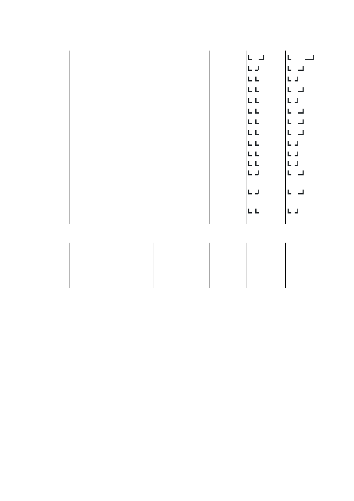
Format Designation Type Size in inches in mm
Side guide
off No format size -- -- -EXEC Executive Paper 7 1/4 x 10 1/2 184 x 267
LETT Letter Paper 8 1/2 x 11 216 x 279
LEGA Legal Paper 8 1/2 x 14 216 x 356
54
Page 58
A4 DIN A4 Paper 8 1/4 x 11 11/16 210 x 297
A5 DIN A5 Paper 5 13/16 x 8 1/4 148 x 210
MONA Monarch Envelope 3 7/8 x 7 1/2 98 x 190,5
C10 Com-10 (Business) Envelope 4 1/8 x 9 1/2 105 x 241
INTD International DL Envelope 3 7/8 x 7 1/2 98 x 190,5
C5 International C5 Envelope 6 3/8 x 9 1/64 110 x 220
INSD Inserter DL Envelope 4 1/2 x 9 1/64 114 x 229
C6 International C6 Envelope 4 1/2 x 6 3/8 114 x 162
A6 DIN A6 Paper 4 1/8 x 5 13/16 105 x 148
CRD1
CRD2
HAGA
B5
USER
File card 1
File card 2
Hagaki
Enter format width in
mm
File card
File card
Envelope
Envelope
Paper
4 x 6
5 x 8
3 15/16 x 5 13/16
6 15/16 x 9 27/32
max. 30
102 x 152
127 x 203
100 x 148
176 x 250
max. 762
Overview of the format sizes that the USERS can enter.
These format sizes are not supported in the printer menu.
B4 9 27/32 x 139/10 250 x 353
B6 4 9/10 x 6 15/16 125 x 176
C4 9 1/64 x 12 3/4 229 x 324
E4 11 x 15 3/4 280 x 400
Left Margin (mm)
• Setting the left margin in a range of 0 – 304 mm.
• The change in the value is carried out in mm increments; when the next or prev
keys are held down, the change in value is carried out in cm increments.
Offs. Edge (mm)
The shifting of the measured paper from 0 through 304 mm. For the user, it would
appear as if the left margin would become enlarged. This is necessary with:
• Window programs in which the left margin cannot be changed.
• Printing of large envelopes with Windows Mail Merge, when the desired printing
position cannot be set on the PC.
55
Page 59

Font Parameter
Font
13 fonts or font sized have been built into the machine. A font selection can be made
here.
Character Spacing
Increase the character spacing in dots of 0 to 90.
Character Set
National character sets with some special symbols for the applicable foreign language.
Type of Barcode
The following barcodes may be selected:
Option Barcode Option Barcode
Zip Barcode USA co39 co39-Barcode
bpo4 Barcode Great Britain co93 co93-Barcode
kix Barcode Netherlands c128 c128-Barcode
2/5 i 2/5 interleaved-Barcode ean EAN-Barcode
Coda coda-Barcode off No Barcode
Æ
Zip ----
C128
2/5i
coda
Co39
Co93
---------Æ Small Width ------------ 1…..99 Dots
---------Æ Large Width ------------ 1…..99 Dots
---------Æ Barc. Height ------------ 1…..999 Dots
ean ---------Æ Barc. Height ------------ 1…..999 Dots
AUTO CHECK DIG. ------------------Æ ON/OFF
Paper Sensor
In order to process print objects with black areas, you can switch off the paper light barrier
during printing. For this purpose, you must definitely set the format size under PAPER SIZE
(an incorrect format size can lead to printing outside t he paper area).
With a switched off paper sensor and a preset format size, the light barrier only queries at
paper infeed.
56
Page 60
Dos Mode
Linemode
This makes possible address separation, through a certain number of line breaks.
HEX to ASCII
Conversion from HEX to ASCII.
When the conversion is switched on, then the printer interprets
the percent sign “%“ as an unprintable control character. Both
characters following the % character will be interpreted as HEX
values, e.g. %0C = Form Feed.
Auto. LF
This menu is used to determine how the printer should interpret control characters:
CR = Carriage Return
LF = Line Feed
FF = Form Feed
The settings mean:
off: CR = CR LF = LF FF = FF
on_1: CR = CR + LF LF = LF FF = FF
on_2: CR = CR LF = CR + LF FF = CR + FF
on_3: CR = CR + LF LF = CR + LF FF = CR + FF
6.7 Service
Test Pattern = Selection of test address 1 or 2.
Hardware test
Display:= Testing the graphic display. Many different characters are shown in order
to test the function of the display.
Key test:= All buttons which are pressed are confirmed by being shown in the display.
Ram Test:= All RAMs on the CPU are tested. If an error occurs, this is shown on the
display.
Ram Test Cont.: = Continuous testing of the RAMs until the test is ex ited manually.
NV Ram Test Cont.: = Continuous testing of the transient RAMs.
Speed Measurement: = Shows the actual speed.
Paper Sensor = To check if the paper sensor is working- Free or not free
Alignment Horiz. = Printing a special test page to test the horizontal alignment.
57
Page 61
Alignment Vertic. = Printing a special test page to test the vertical alignment.
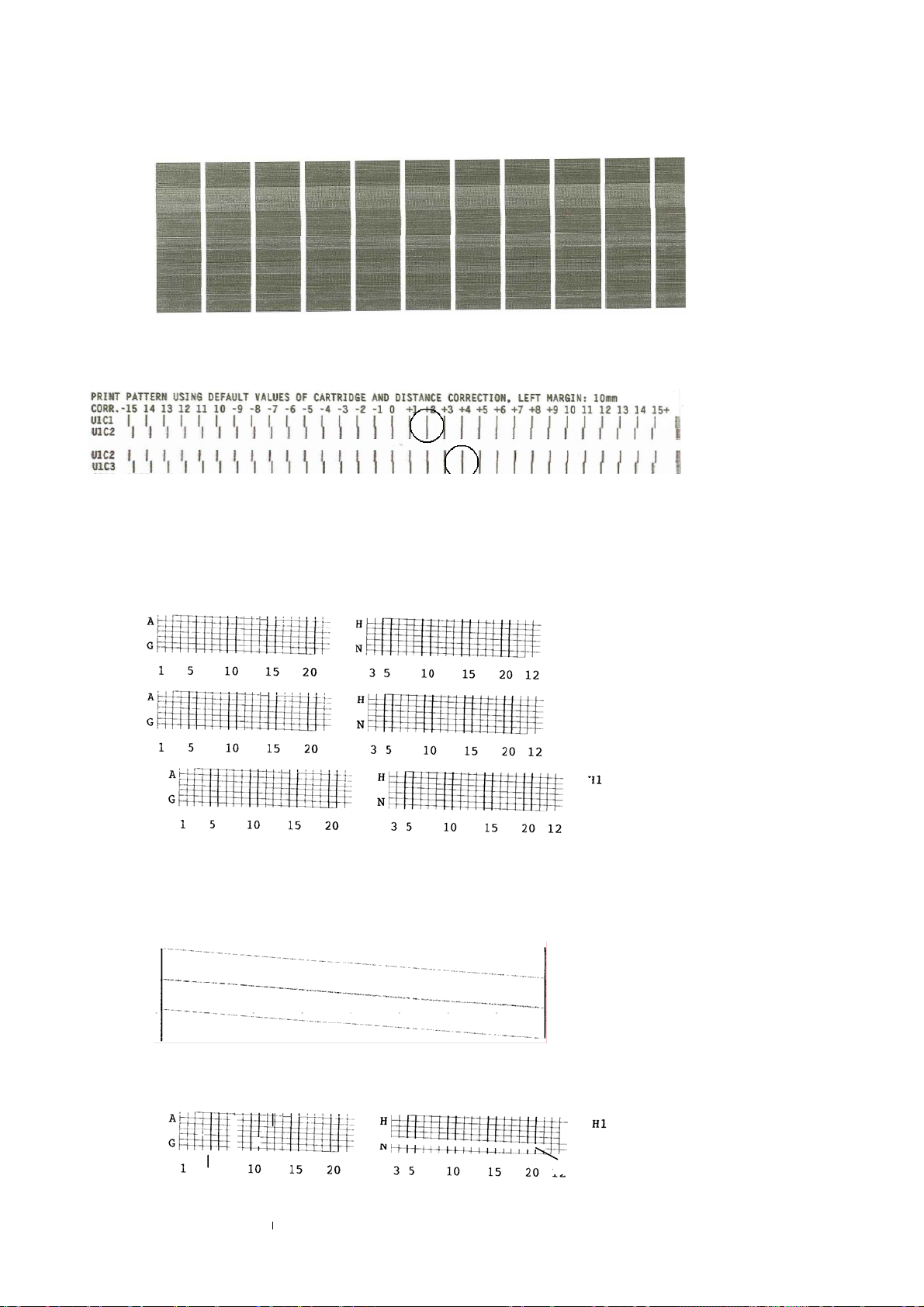
Correction Pattern = Printout to determine the correction value in order to calibrate the car-
tridges.
Cart. Print Pattern
In several test prints for the cartridges.
The contacts to the jets are shown in a grid. (See following page)
Illustration 6-2: Test Print of all cartridges
The contacts for all jets are controlled sequentially and made visible in a continuous slanting
line.
Illustration 6-3: Test Print of all jets
Examples of defective printheads:
58
Page 62

Illustration 6-4: Test print with defective jets
• a.1 = no connection at contact “K“ (with printhead H1)
a.2 = no connection at contact “B“ (with printhead H3)
• b.1 = no connection at contact “10“ (with printhead H1)
b.2 = no connection at contact “16“ (with printhead H3)
• c = these jets are not clean
When a grid or slanting line shows gaps (see illustration above), the contact surfaces and cable contacts of the corresponding printhead are to be cleaned, or the
printhead in question is to be replaced.
Check Cartridge = Display of Pen ID, missing jets, as well as optimization of all cartridges.
LED / Beeper
Upon activation of this function
1: All LED’s are going out
2: The green LED is flashing for ca. 2 seconds and the display shows the function of
this LED.
3: The LEDs are flashing each in turn for ca. 2 seconds and are described on the
display.
4: At last, the beeper makes the beep even for 2 seconds.
Configuration Info
All device-specific data is displayed.
Firmware
SerNr:
Page Cnt
RAM
Hardware
DC: (5V)
Printing Setting Dump
Printout of the 10 setting configurations; 9 sheets are required.
Printing Input Dump
With this function, the entire reception buffer is printed with PC8 symbols.
The entire printout requires approximately 180 sheets. Prior to the dump print,
switch the machine off and on again. Send the print job, and then start the dump
59
Page 63
print. The required data is now at the front of the buffer. Stop the procedure using
the end key.
Print Character Set
Printout of the character set.
6.8 Language
The displayed text can be shown in different languages: English, German, French,
Italian and Spanish.
6.9 Setting
An individual configuration can be created for each of the different applications.
Configuration No. “0“ is for the factory setting; no changes can be made here.
The configurations “No 1 through No 9 “can be individually set.
When exiting the programming mode, the changes carried out in the selected setting
number are saved.
Individual parameters can be L
der the menu field.
ocked. Locked parameters are indicated by an “L“ un-
(When parameters are L
ware applications can occur. Example: When the left margin is
Locked, but the software application carries out absolute horizontal positioning. Other conflicts are also
possible).
• After switching off the machine, the set configurations are maintained.
• With a factory initialization (Quick key is held down when switching on the
machine), all configuration settings are set to factory settings.
ocal Locked, incompatibility with soft-
6.9.1 Example of an Application in the Programming Mode
Suppose you would like to set a configuration, changing the vertical line spacing
from 6 lines / inch to 8 lines / inch.
Switch the machine on.
Programming Mode
Press the "Offline" button.
Activate desired menu field
Change with the "Home" key in the main menu. Press the "Arrow Down" key, select
the menu "Job Parameter" and confirm with "Arrow Right" In this submenu, you will
find the menu "Font". Confirm it with "OK" and you get other submenus. With "Arrow Down" or "Arrow Up" move to the desired menu field i.e. "Line spacing" and
confirm it with "OK".
With the "Arrow down" or "Arrow Up" key, you are able to set the parameter to "8".
60
Page 64

Press the "OK" key. The changed value is saved in the configuration under the selected "Setting No", and the machine is again in offline mode
or
press the "Online" key. The machine is again in online mode, so that the print job
can be resumed immediately.
6.9.2 Initialization of the Machine
Without loss of configuration
In order to access the factory configuration, select in programming mode and in
menu field "Setting" the option "No 0". When the "ENTER" key is pressed, the programming mode is ended. "Set 0U" may appear on the display. The set configuration is maintained under your corresponding setting number (compare with menu
item "Setting").
With loss of configuration
In order to restore all changed values and configurations, switch off the machine.
When restarting the machine, press and hold down the "Quick" key.
The following appears on the display:
PRINTER 830/930 PPC
Default Reset
The machine now has the factory settings, and all configurations are those of the
factory. "Set 1U" may be displayed.
61
Page 65

7 Troubleshooting
7.1 The Meaning of Some of the Display Notes
• ??? blinks
Data/Addresses were transmitted, but there is no print object.
• NoD blinks.
The last data/addresses are incomplete (FormFeed is missing)
• Wait blinks.
Printing has halted, because the control character EOT was sent.
Printing can be resumed with the start key.
• Off blinks.
The printing is stopped for a few seconds, because a pause is being set via
sequences. Printing starts when the set time has elapsed.
62
Page 66
7.2 Error Messages
Error Messages Cause Remedy
NO PAPER !!
PAPER JAM OR
WRONG PAPER LENGTH!
NO INK !!
CHANGE CARTRIDGE
CHECKSUM ERROR!
MAKE DEFAULT RESET
CHECKSUM ERROR!
MAKE COUNTER RESET
CHECKSUM ERROR!
TESTMACRO RESET
CHECKSUM ERROR!
SETTING RESET
CHECKSUM ERROR!
RESET PENVALUES
TEST MACRO TOO LONG
BUFFER OVERFLOW !!
RAM ERROR !!
VERIFY RAM
No paper Insert paper
Paper jam Check paper width
The cartridge is empty.
Error in the buffered RAM
Error in the buffered RAM
Error in the buffered RAM
Error in the buffered RAM
Error in the buffered RAM
The user-defined test ad-
dress is too long
Overflow of reception
memory.
RAM error on the CPU
board
Insert a new cartridge and
reset the counter.
Factory setting
(PROG key)
Default factory setting
(ONLY for technicians)
Factory setting
(PROG key)
Factory setting
(PROG key)
Factory setting
(PROG key)
Be aware of the maximum
length.
Check connection to the
PC.
Replace the CPU board.
UNPRINTED ADDESSES!
FINISH THE JOB
PROGRAM ERROR
MAKE DEFAULT RESET
UART TIMEOUT
RESET THE PRINTER!
DISPLAY TIMEOUT
RESET THE PRINTER!
ERROR FPGA Ready
CALL SERVICE
CHECK CARTR.
START TO CONTINUE
PRINTING ERROR
REPEAT LAST ADDRESSES
Reduce Pap. Speed! U#
START to continue!
Feed Motor Jammed!
START to Continue
Feed Motor Controller
Fault! Call Service
Address is not completely
printed.
Error in the program flow.
Error in the UART chip or
FET transistor
Error with display controls.
Error FPGA-IC Replace the board
Cartridge is not inserted Insert missing cartridge(s)
Severe error
Transport speed too high
for the printing unit #
Error with motor control Remove paper jam
Fault initializing motor-IC Replace board
Make no changes in the
programming mode while
a print job is in progress!
Factory initialization - reload firmware
Replace the CPU board
Switch off printer
Check cable connection
Replace display unit
Reduce speed or data vol.
Update Flexmail or mailing
software
63
Page 67
Error Messages Cause Remedy
ERROR PEN BOARD# U#
CALL SERVICE
RAM ERROR
CALL SERVICE
PRINTER ERROR
WRONG BOARD/FIRMWARE
CPU-HW-ERROR #
RESET THE PRINTER!
ERROR CARTRIDGE
CHECK CONNECTION
FONT ERROR
LOAD FLASH FONTS!
PAP. LEN TOO SMALL
MIN. VALUE:
ERROR PAPER SENSOR
CHECK THE SENSOR
Font Loading
ERROR: TIMEOUT
Font Loading
ERROR:HEADER (SB)
Font Loading
ERROR:HEADER (F)
Font Loading
ERROR:FONT ORIENT
Font Loading
ERROR:CHAR. HEADER
Font Loading
ERROR:MEMORY (RAM)
Font Loading
ERROR: CHAR. No.
Font Loading
ERROR:SUPPL. CHAR.
Font Loading
ERROR: CHAR: LasFt
Font Loading
ERROR: DATA LasFt
Font Loading
ERROR:CHAR. HEIGHT
Font Loading
ERROR:DL DISABLED
MACRO LOADING ERROR
RAM MEMORY IS FULL!
Macro Too High
Reduce To 5 Inches
Error of the HP PEN
board# #=1,2,3
CPU board with small RAM
memory
Severe CPU error
Cartridge error or TSR is
wrong
Check plug connection
Replace PEN board
Replace CPU board.
Install correct board and
firmware
Reload firmware; check
the checksums!
Check plug connection
Replace cartridge
Error in flash PROM. Reload fonts
Paper too short Observe minimum length
Paper light barrier
Error in download font Check download font
Error in download font Check download font
Error in download font Check download font
Error in download font Check download font
Error in download font Check download font
Error in loading the font
insufficient memory
No more space for the
font in the memory
Error in download font Check download font
Error in download font Check download font
Error in download font Check download font
Error in download font Check download font
Error in download font Check download font
Error in download font Check download font
Error in loading macro:
memory is insufficient
Macro is too high
Macro no longer fits in the
memory
Reduce graphic height to
38.1mm
64
Page 68
7.3 Warning Messages
Warning Message Cause Remedy
Warning:Non-Existent
Font Selected!
Warning:Non-Existent
Macro Selected!
Error Macro ID
Contact FlexSystems!
Error Macro ID
Report Err. 2 Vendor
Position Warning!
Reduce Left Margin!
Warning:Wrong Data/
Barcode Selected!
Error Barcode Data
Contact FlexSystems!
Error Barcode Data
Report Err. 2 Vendor
Macro Too Large Or
Wrong Hor.Position!
Macro Height Does
Not Match!
Macro ID# In Use
Macro Load Ignored!
Image Height Exceeds
The Maximum Value
Selected font does not
exist in the printer
Selected macro does not
exist in the printer
Error in FlexMail program or in the Mailing
Software
Error in the Mailing
Software
Paper length or address
position are wrong
Error in PC program Error in PC program
Error in FlexMail program or in the Mailing
Software
Error in the Mailing
Software
Macro too wide Comply with maximum
Error in macro
Macro (same number)
already exists, overwriting not possible
Print data outside of the
printing area
Printer is switched off and
the PC sends remaining
data
After the job has ended,
the addresses cannot be
repeated.
Faulty PC program.
Contact your dealer
Contact your dealer
Check paper length,
Reduce left margin in the
PC program
Contact your dealer
Contact your dealer
width for macros you create:
Graphic always upper left,
then convert to macro
Delete macro, define it
again
65
Page 69
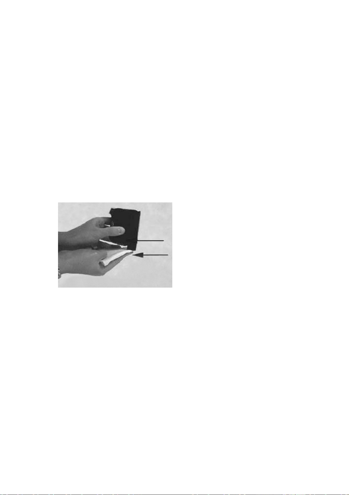
8 Appendix
8.1 Maintenance Notes
8.1.1 Cleaning the Ink Cartridge
Clean the jets of the ink cartridge with a cleaning wipe like the TexWipe® brand.
The following materials are NOT suitable for the cleaning of the printhead
and the ink cartridge!
• Paper towels
• Toilet paper
• Sponges
• Cloths with abrasives or small fibers that can collect on the jet plate of the
cartridge
• Dry cloths
To achieve an optimum print quality, move the wipe in the direction of the jet rows
(see the following Illustration):
Illustration 8-1: Cleaning the cartridge
8.1.2 Press Roll and Rollers
Make certain that the press rolls and rollers are always kept clean.
After printing, store the cartridges in an upright position in a sealed plastic container, in order to prevent the ink from drying.
8.2 Interfaces
The PRINTER 830/930 is equipped with two standard print-data interfaces. They
both offer the possibility of connecting the printer to a computer.
• USB 1.1
• IEEE1284 (Centronics, parallel)
In addition, the PRINTER 830/930 has a control/status interface:
• RS-232-C serial
The interface connector sockets are located on the rear side of the machine.
66
Page 70
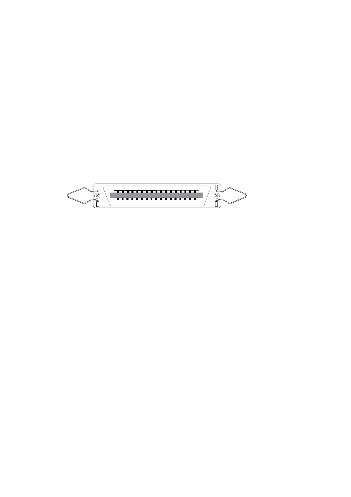
8.2.1 Centronics Parallel Interface
The PRINTER 830/930 is equipped with a standard Centronics parallel interface.
This interface is most frequently used as a connection to a personal computer.
Unlike the RS-232-C serial connection, there are usually no special commands or
configurations for the printer or computer necessary here. In addition, data is
transferred quickly with the Centronics parallel interface cable.
The parallel interface connector is a standard 36-pin Amphenol ty pe with two metal
retaining clips.
8.2.1.1 Connector Socket
Plug type: Amphenol female connector strip
Production series: 57 - 40360
Max. cable length 2 m with
Amphenol multipoint connector 57 – 30360
Illustration 8-2: Parallel interface connector socket
The signal description is found on the following page.
67
Page 71
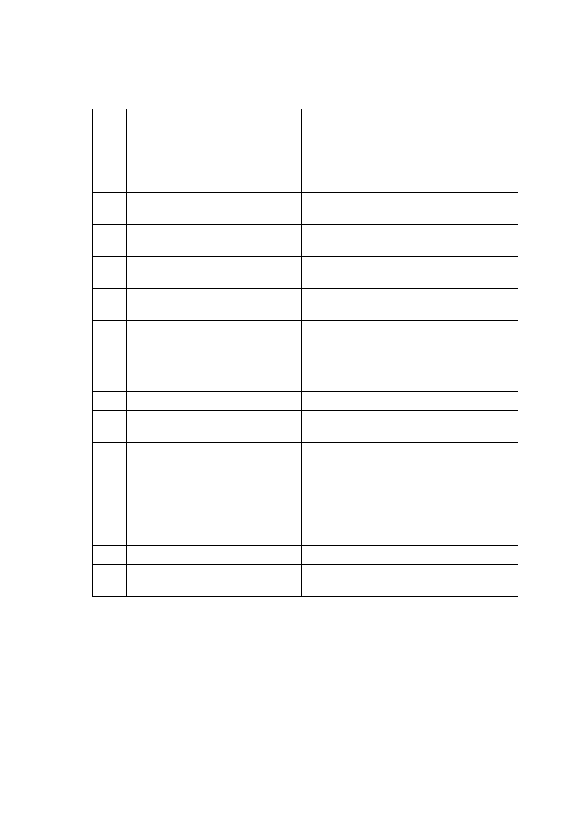
8.2.1.2 Signal Description
PIN Corresponding
GND
Signal Signal-
Meaning
I/O
1 19 STROBE I This pulse 0.5µs) reports that
data bits are valid
2-9 20-27 DATA 1-8 I Data bits D0-D7
10 28 ACKNOWLEDGE O Printer reports: Data has been
processed (is ready to receive)
11 29 BUSY O Printer reports: Data received,
data being processed
12 30 PE (Paper
empty)
13 -- SELECT
(Online)
O Printer reports to the com-
puter: No paper available
O Signal is high, when the printer
is online
14 -- Autofeed I No function, only for bi-
directional interface
15 -- Free Free
16 -- GND GND
17 -- Chassis-GND Chassis GND
18,
-- + 5V + 5V above 0.2A Si
35
19-
-- GND GND
30
31 -- INIT I Resets printer
32 -- ERROR O Signal is low, when there is an
error in the printer
33 -- GND GND
34 -- Free Free
36 -- SELECT IN I No function, only for bi-
directional interface
68
Page 72

8.2.1.3 Pulse Diagram
Illustration 8-3: Parallel interface pulse diagram
8.2.2 RS-232-C Serial Interface
This segment describes the RS-232-C serial plug connection and the concept of a
serial interface connection. The PRINTER 830/930 has a standard RS-232-C serial
interface, which is compatible with most computers and terminals.
8.2.2.1 Connector Socket
The PRINTER 830/930 has a standard DB-9 serial connector socket
69
Page 73
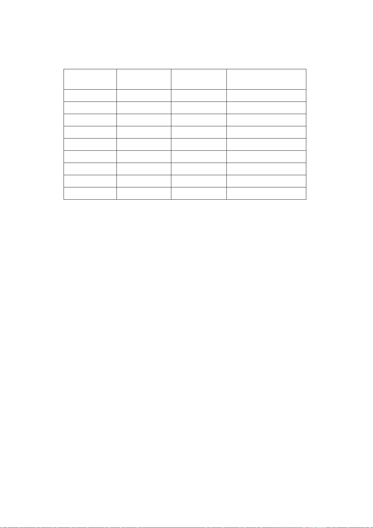
8.2.2.2 Plug Assignment
PIN Signal Signal
Input/Output
Meaning
1 --- - free
2 R x d I Received data
3 T x d O Transmitted data
4 DTR O Data Terminal Ready
5 GND - Signal Ground
6 --- - free
7 RTS O +12V
8 CTS I Clear to Send
9 --- - free
Pin 2
Received Data (RxD):
Serial transfer of data from the computer to the printer.
Pin 3
Transmitted Data (TxD):
Serial transfer of data from the printer to the computer system or the terminal (e.g.
XON/X
OFF symbol
).
Pin 4
Data Terminal Ready (DTR):
Printer output, which allows the tr ansfer of data to the printer or which interrupts it
(handshaking). Data transfer is possible, when DTR is high. It is not possible, when
DTR is low.
Pin 5
Signal Ground (GND):
The reference potential for the entire data exchange.
Pin 7
Request to Send (RTS):
This signal is always high with a switched on printer.
Pin 8
Clear to Send (CTS):
Input of the printer, which allows the transfer of data to the computer or which interrupts it. When the input is high, then the printer may transmit the data. For the
software handshaking with Xon/Xoff, this input must always be high.
70
Page 74
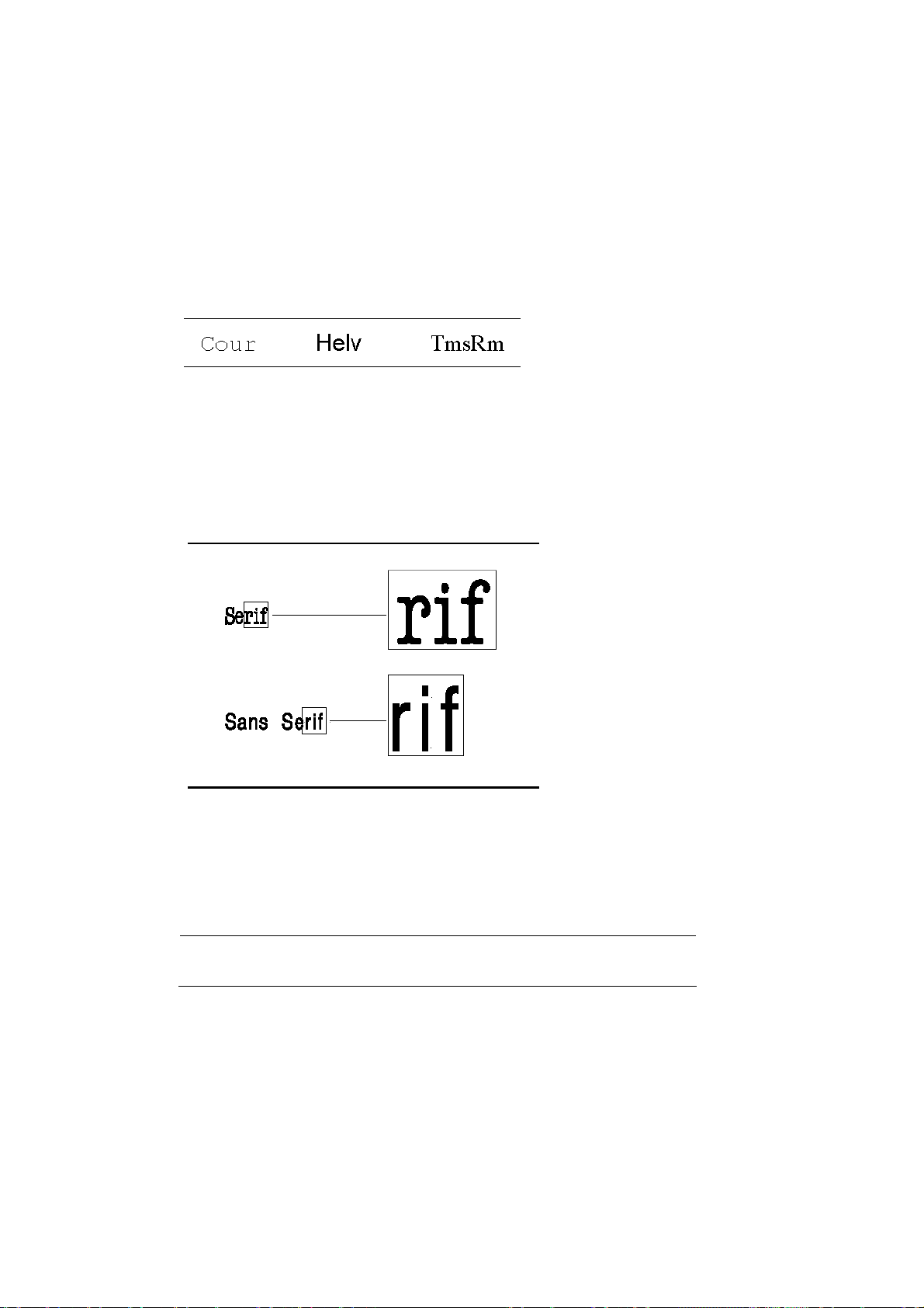
8.3 Fonts
8.3.1 Terminology
A font is a collection of characters and symbols having the same typeface, spacing
size (height), line width and font slant.
8.3.1.1 Typeface
Typeface is a set of characters and symbols with a certain design.
8.3.1.2 Serif or Sans Serif Typefaces
Serifs are small lines on the top or bottom of a character (so-called “feet” on
Bodoni book type). Cour is a serif typeface Typefaces without serifs are referred to
as sans serif. Helv is a sans serif typeface. The following illustration shows the difference between a serif typeface and a sans serif typeface.
Illustration 8-4: Serif and sans serif
8.3.1.3 Font Slant
The characters can either be printed standing straight (normal) or - at a constant
angle - standing slanted (italic).
This example shows straight standing characters.
This example shows characters standing at a slant.
8.3.1.4 Spacing
Spacing refers to the relative print density between the letters of a font. The character spacing is either fixed or proportional.
71
Page 75
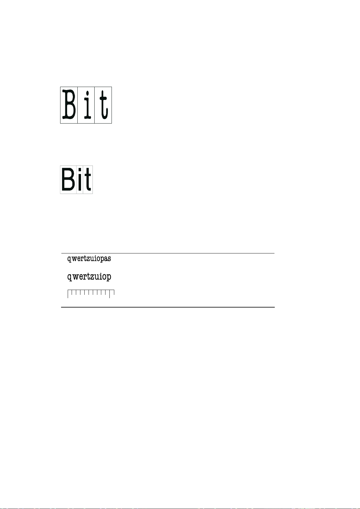
Fixed Spacing
With fixed character spacing, every letter of a font takes up the same width space
and has the same spacing as neighbouring letters. Cour and LetGot are fonts with
fixed character spacing.
Illustration 8-5: Fixed character spacing
Proportional Spacing
With proportional character spacing, the spacing depends upon the width of the letter. Helv and TmsRm are fonts with proportional character spacing.
Illustration 8-6: Proportional character spacing
8.3.1.5 Character Density
Character density (pitch) refers to the number of printed characters within a linear
inch. A font with a character density of 10 cpi prints 10 characters per horizontal
inch (cpi = characters per inch). The character density can only be provided for
fonts with fixed character spacing.
0” 1”
12 characters per inch (12 cpi)
10 characters per inch (10 cpi)
72
Page 76
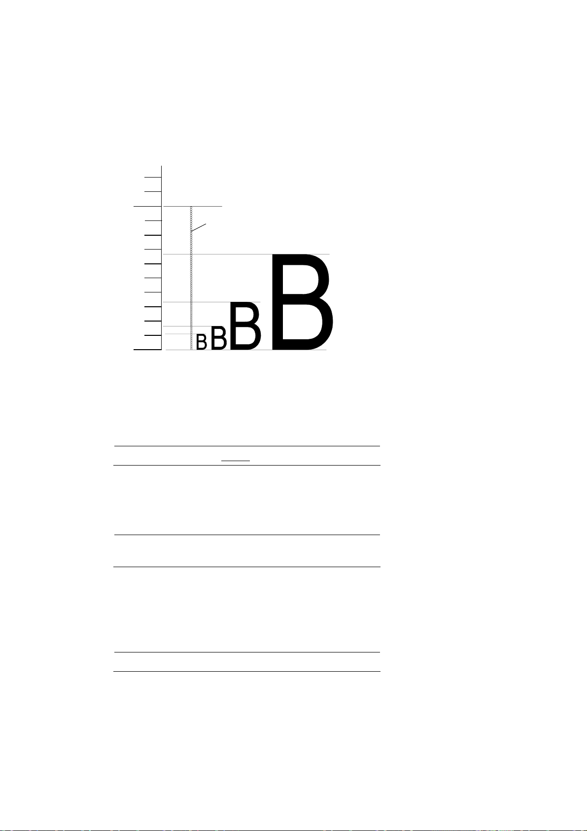
8.3.1.6 Character Size
Character size (character height) refers to the height of a printed capital letter. It
is measured in pica points. A point is 1/72 of an inch.
The height for both fonts, with fixed and proportional character spacing, is measured in pica points.
72 Punkte = 1 Zoll
1
Pica- Punkt
48 Punkte
(Zoll)
24 Punkte
12 Punkte
8Punkte
0
Illustration 8-7: Character size
8.3.1.7 Underline
In order to especially emphasize a point of text, you can underline it. Your uniform
font face is thereby maintained.
You can underline a single
8.3.1.8 Wide Font
The address image can be printed (e.g. for a large parcel) twice as wide, while
maintaining the proportional character width / spacing.
This is normal width.
This is wide font.
8.3.1.9 Character Spacing
In order to especially emphasize individual words, you can increase the space between letters and words without changing the character size itself.
This E x a m p l e is printed voluminously.
word.
8.3.1.10 Quality
Quality refers to the print quality.
You can make a selection among the following print qualities [dpi x dpi]:
73
Page 77
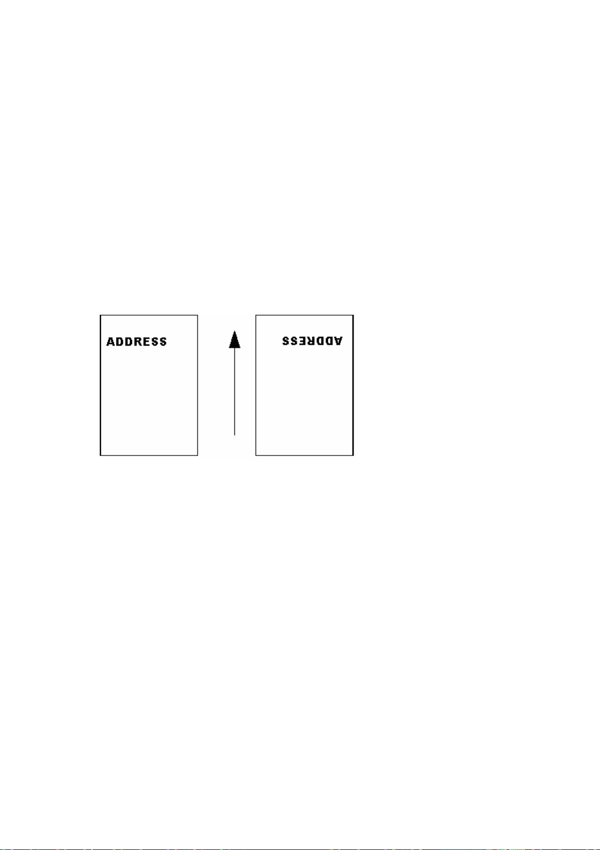
1x3 corresponds to 150x300
1x6 corresponds to 150x600
2x3 corresponds to 200x300
2x6 corresponds to 200x600
3x3 corresponds to 300x300
3x6 corresponds to 300x600
6x3 corresponds to 600x300
6x6 corresponds to 600x600
8.3.1.11 Print Direction
The print direction refers to the (readable) address position on the print object. It
can be turned around 180°. The arrow in the illustration marks the direction of the
print run.
Nor Rev
Illustration 8-8: Print direction
Note the information for the image storage capacity in the menu item „HErreur !
Source du renvoi introuvable.“ on page Erreur ! Signet non défini..
74
Page 78
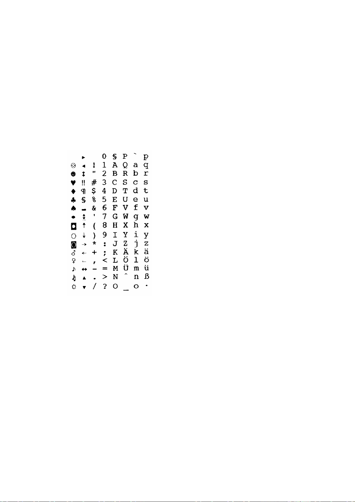
8.3.2 Character Set
A character set consists of characters and symbols, which contain all elements of a
language or discipline (country-specific characters), including punctuation marks
and numbers.
8.3.2.1 7-Bit Character Set
A 7-Bit character set corresponds to definitions of the ”International Standards Organisation“ (ISO) and the ”American Standard Code for Information Interchange”
(ASCII).
In a 7-Bit character set there are 128 characters.
The following is a depiction of a 7-Bit character set .
Illustration 8-9: 7-Bit character set Ger7
75
Page 79
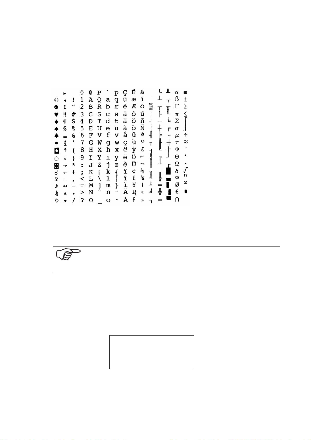
8.3.2.2 8-Bit Character set
In the 8-Bit character set there are 256 characters.
Many national characters are available with this. The following is a depiction of the
most frequently used 8-Bit character set.
Illustration 8-10: 8-Bit character set PC8
8.3.3 Selection of the Fonts for Printing
The fonts are selected via the software or printer commands.
Fonts can be used with great precision, in order to lend a print object a specific appearance.
Select the fonts that suit best the content of your text.
8.3.3.1 Serif Typefaces
The following example shows an address with the Cour12 typeface:
Test print
ADDRESS
PRINTER 830/930
PRINTER LAND
76
Page 80
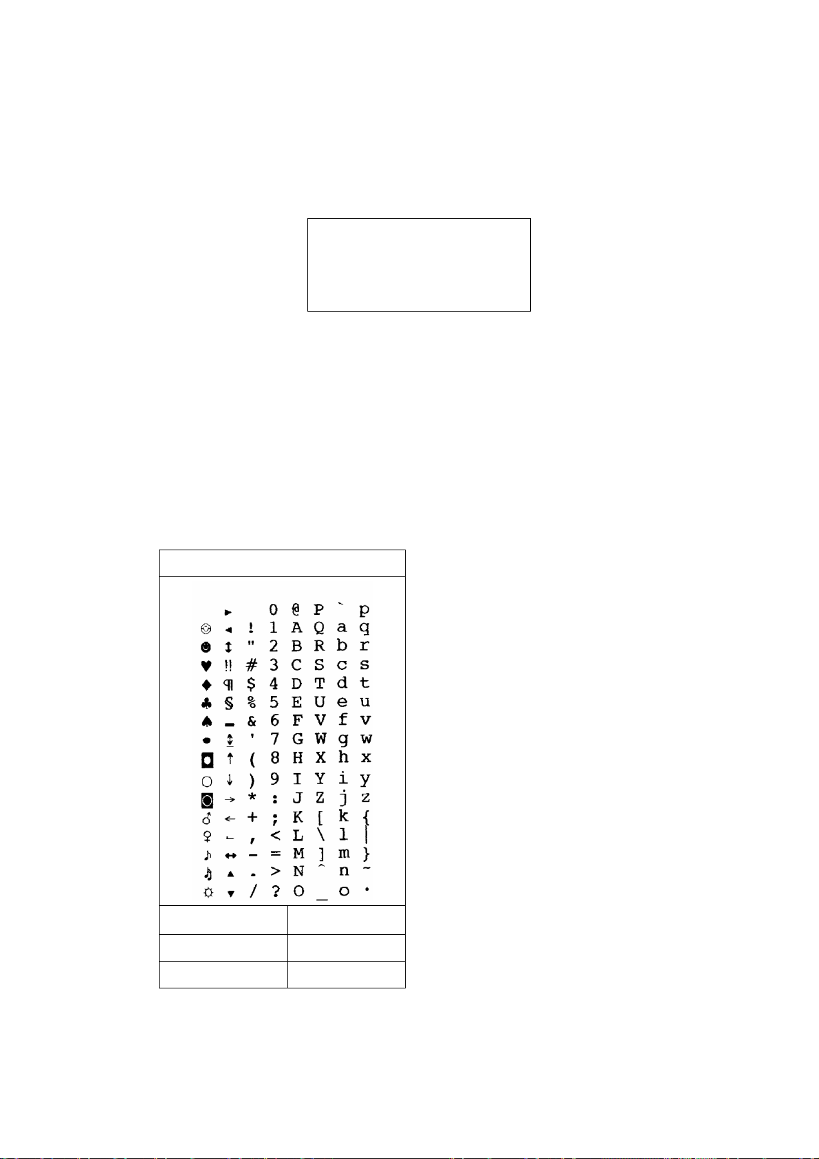
8.3.3.2 Sans Serif Typefaces
The following example shows an address with the Helv12 typeface:
Test print
ADDRESS
PRINTER 830/930
PRINTER LAND
8.4 Character Sets
Note for the depiction of character sets:
• Character set name: The information in parentheses (e.g. USA7) corresponds
to the options field in PRINTER 830/930.
• With the ASCII printer command (e.g. E
set in your software.
8.4.1 7-Bit Character Sets
ASCII (= USA7)
( 0 U) you can call up the character
c
( 0 U
ASCII:
Decimal: 27 40 48 85
Hexadecimal: 1B 28 30 55
77
E
c
Page 81
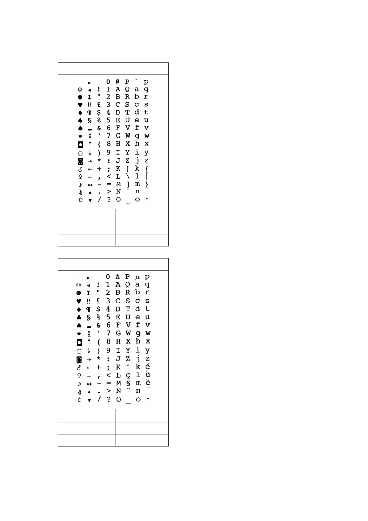
England (= UK7)
( 1 E
ASCII:
E
c
Decimal: 27 40 49 69
Hexadecimal: 1B 28 31 45
France (= Fra7)
( 1 F
ASCII:
E
c
Decimal: 27 40 49 70
Hexadecimal: 1B 28 31 46
78
Page 82
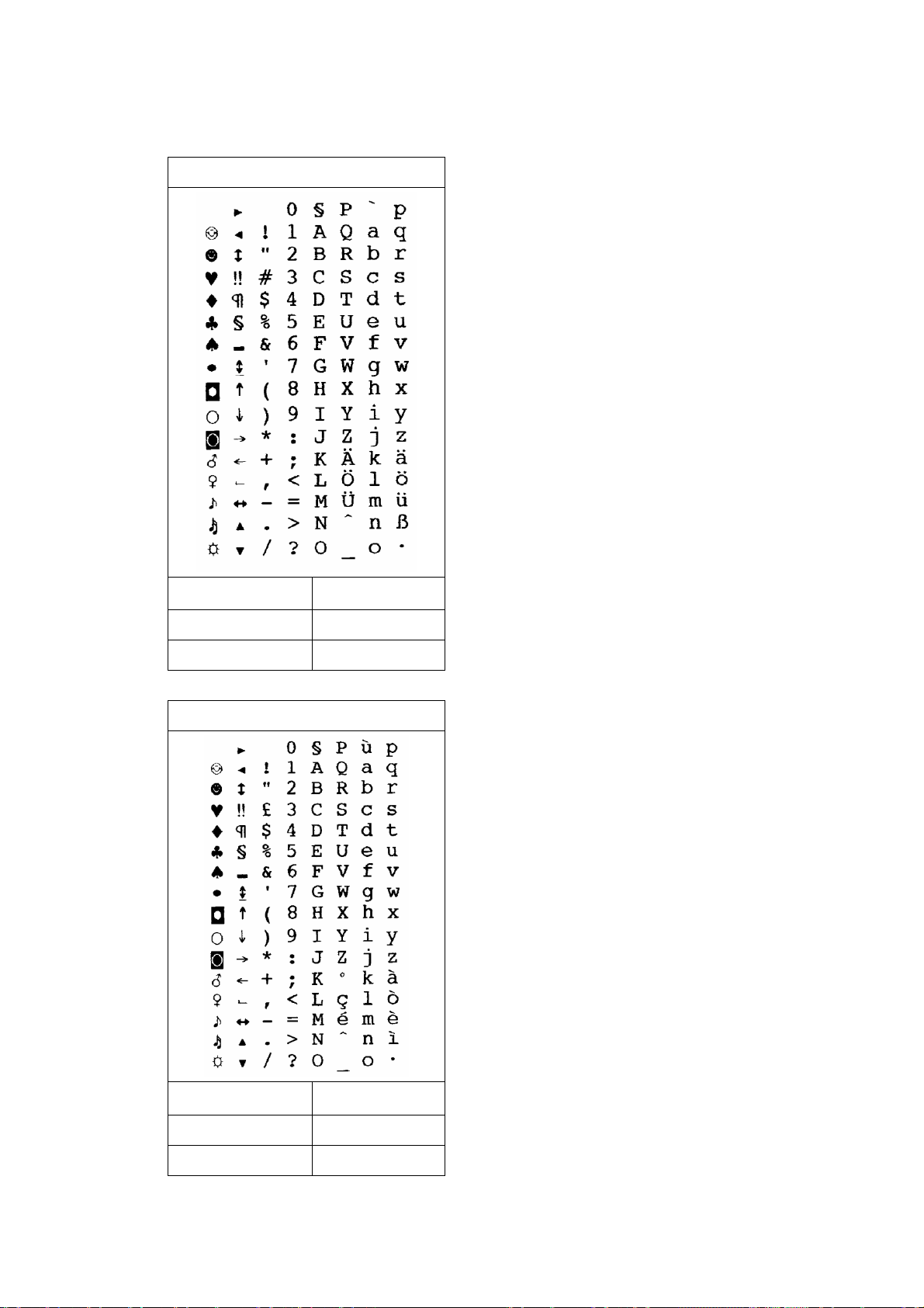
Germany (= Ger7)
( 1 G
ASCII:
E
c
Decimal: 27 40 49 71
Hexadecimal: 1B 28 31 47
Italy (= Ita7)
( 0 I
ASCII:
E
c
Decimal: 27 40 48 73
Hexadecimal: 1B 28 30 49
79
Page 83
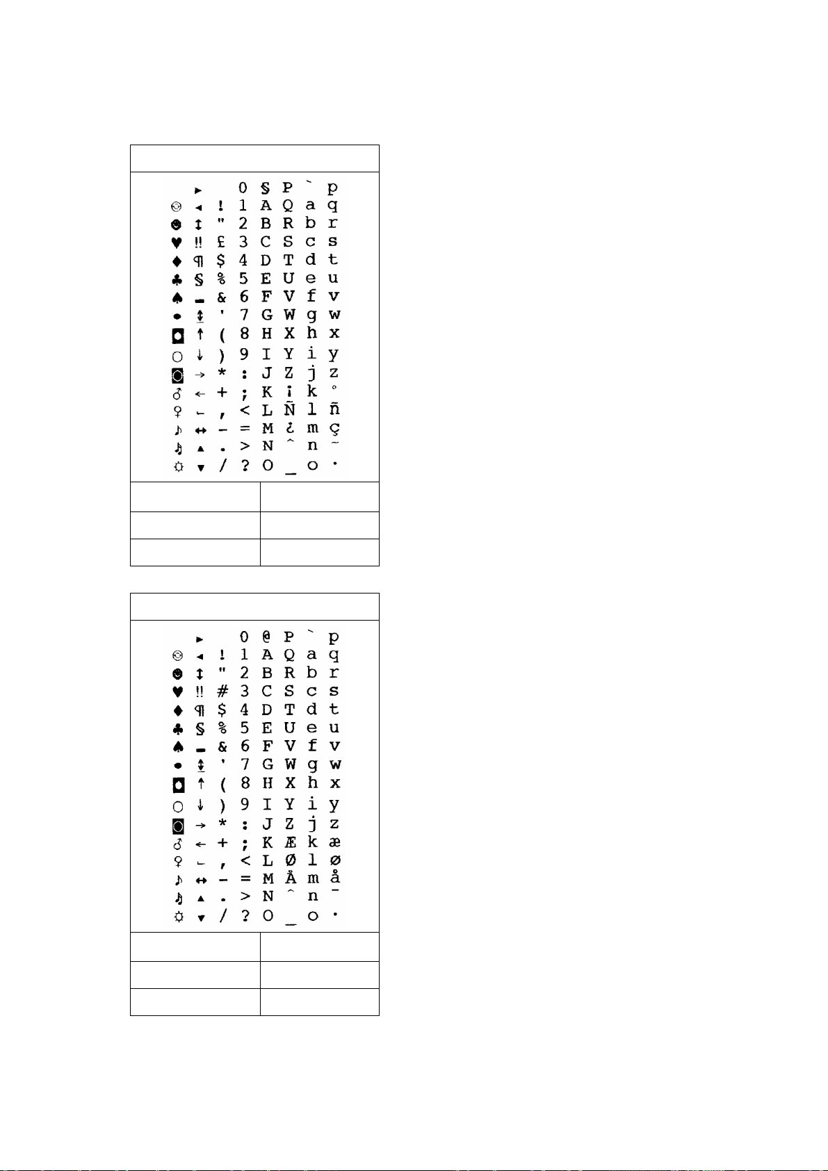
Spain (= Spa7)
( 2 S
ASCII:
E
c
Decimal: 27 40 50 83
Hexadecimal: 1B 28 32 53
Denmark (= Den7)
( 1 D
ASCII:
E
c
Decimal: 27 40 49 68
Hexadecimal: 1B 28 31 44
80
Page 84
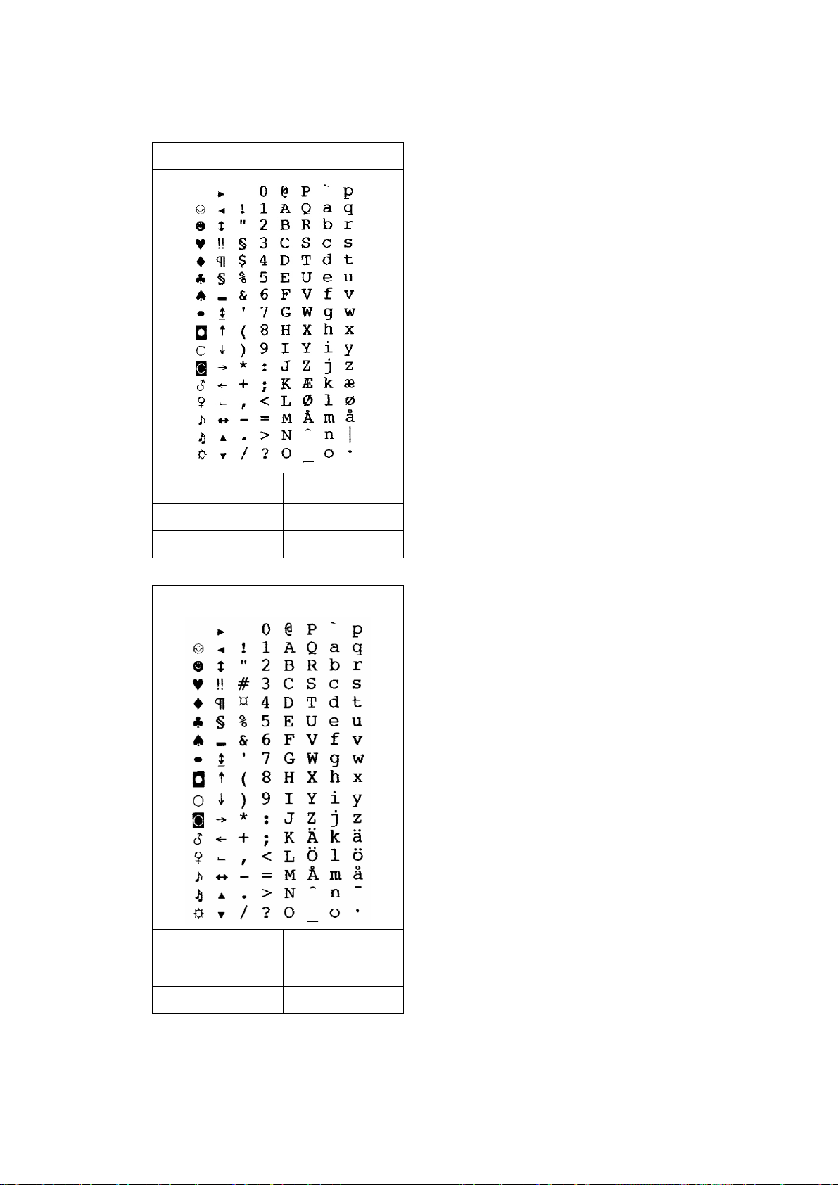
Norway (= Nor7)
( 0 D
ASCII:
E
c
Decimal: 27 40 48 68
Hexadecimal: 1B 28 30 44
Sweden (= Swe7)
( 3 S
ASCII:
E
c
Decimal: 27 40 51 83
Hexadecimal: 1B 28 33 53
81
Page 85
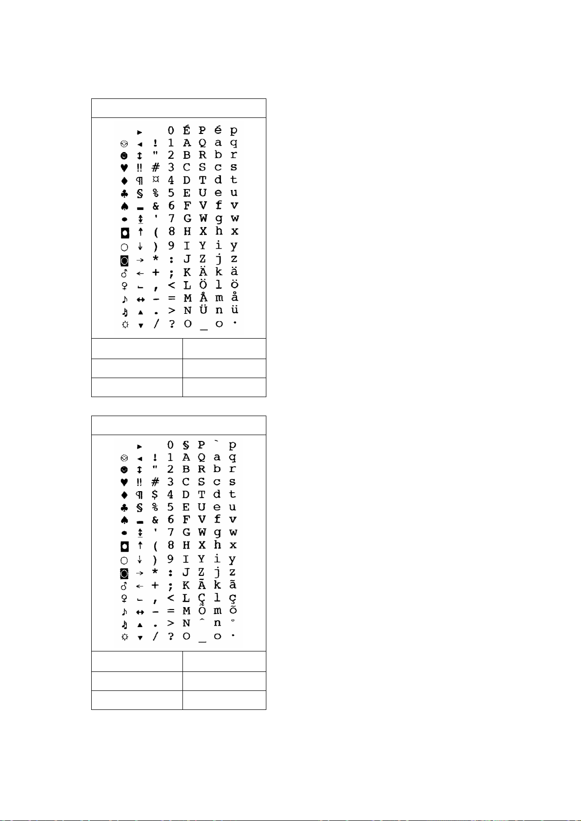
Sweden/Names (= SwN7)
( 0 S
ASCII:
E
c
Decimal: 27 40 48 83
Hexadecimal: 1B 28 30 53
Portugal (= Por7)
( 4 S
ASCII:
E
c
Decimal: 27 40 52 83
Hexadecimal: 1B 28 34 53
82
Page 86
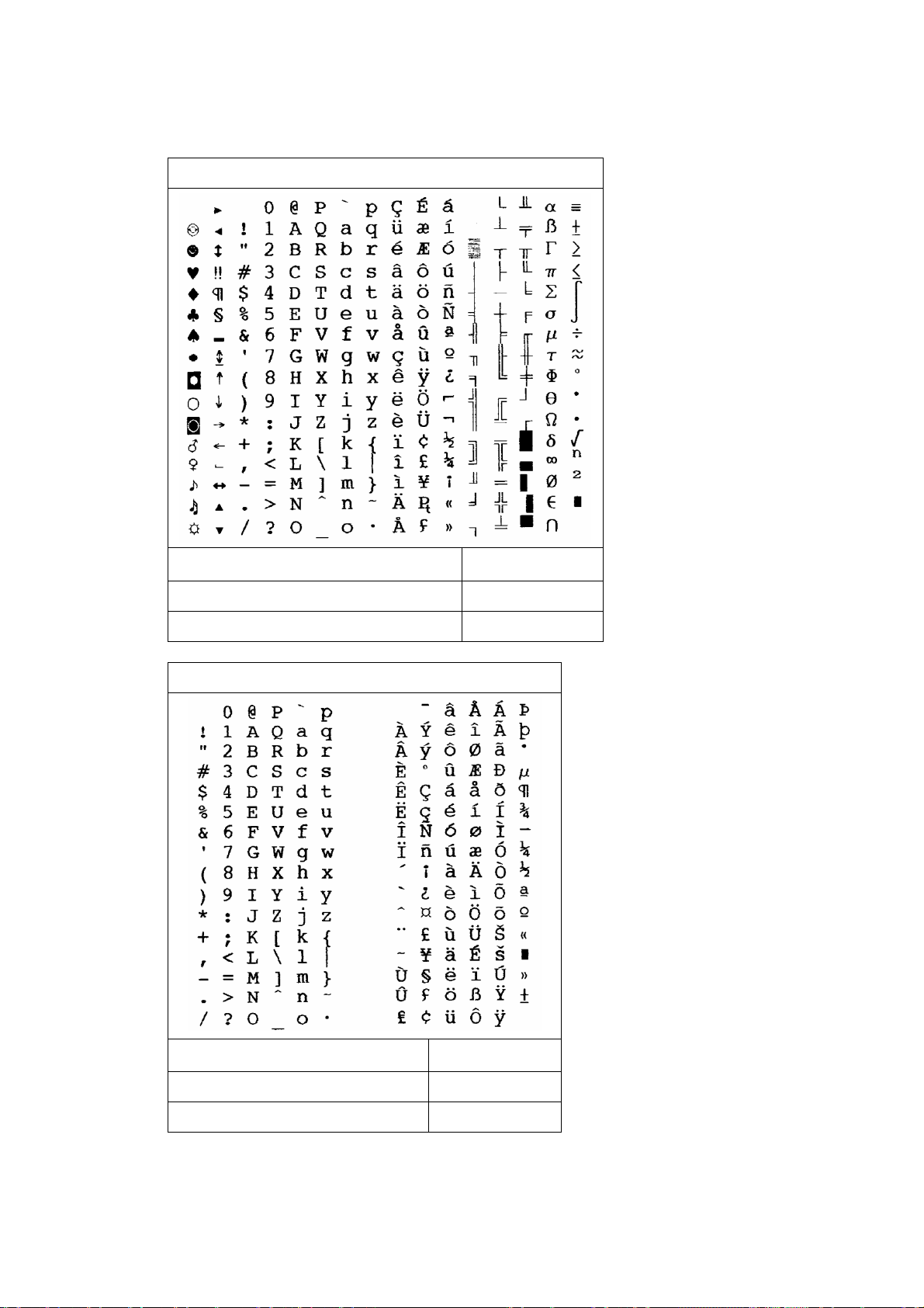
8.4.2 8-Bit Character
PC-8 (= PC8)
( 10 U
ASCII:
E
c
Decimal: 27 40 49 48 85
Hexadecimal: 1B 28 31 30 55
Roman8 (= Rom8)
( 8 U
ASCII:
E
c
Decimal: 27 40 56 85
Hexadecimal: 1B 28 38 55
83
Page 87
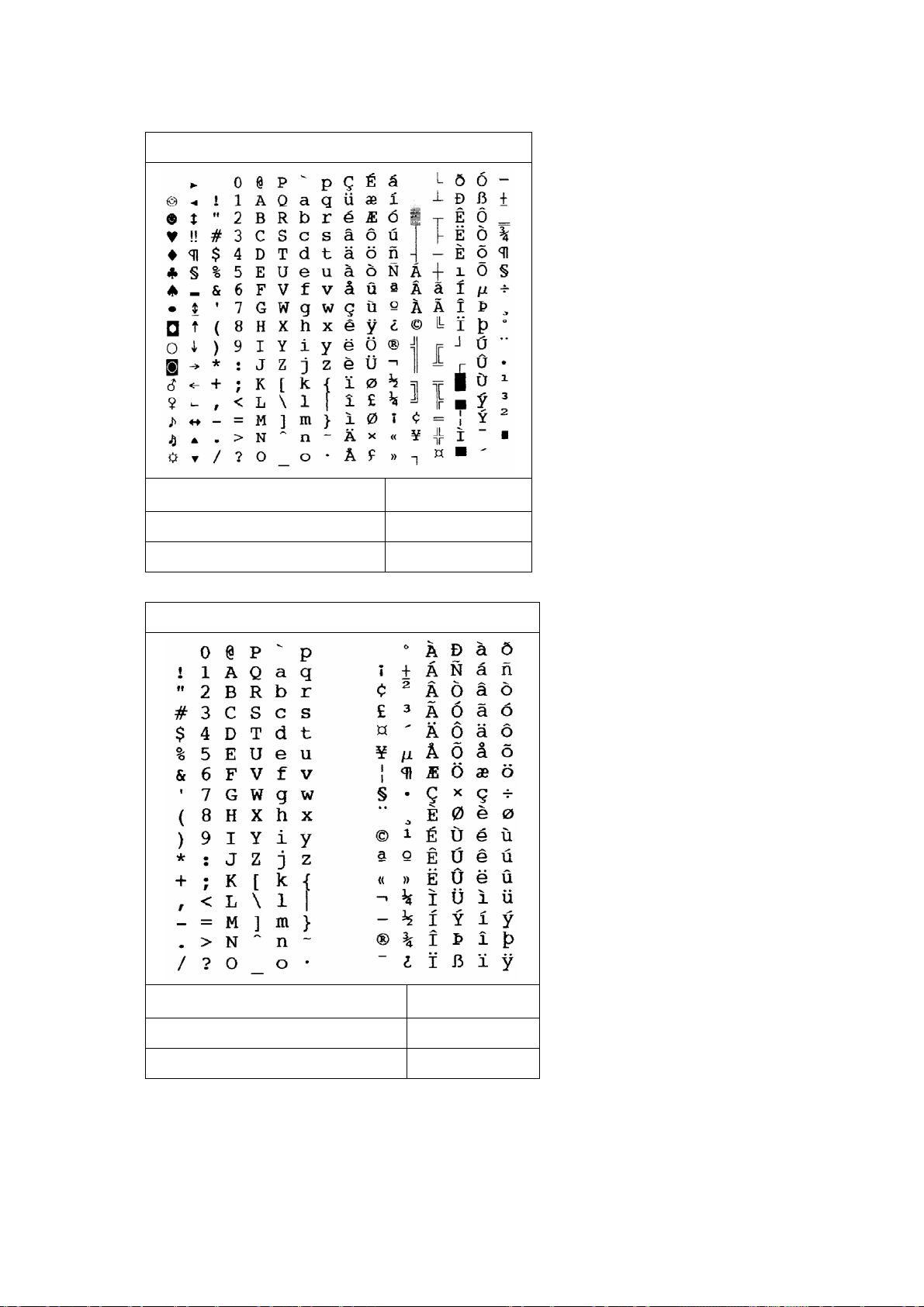
PC-850 (= P850)
( 12 U
ASCII:
E
c
Decimal: 27 40 49 50 85
Hexadecimal: 1B 28 31 32 55
ECMA-94 Latin 18 (= ECMA)
( 0 N
ASCII:
E
c
Decimal: 27 40 48 78
Hexadecimal: 1B 28 30 4E
84
Page 88
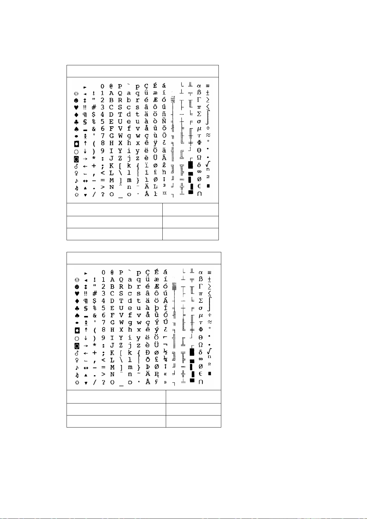
PC-8 Denmark/Norway (= P8DN)
( 11 U
ASCII:
E
c
Decimal: 27 40 49 49 85
Hexadecimal: 1B 28 31 31 55
ICEL (= ICEL)
( 33 O
ASCII:
E
c
Decimal: 27 40 51 51 79
Hexadecimal: 1B 28 33 33 4F
85
Page 89
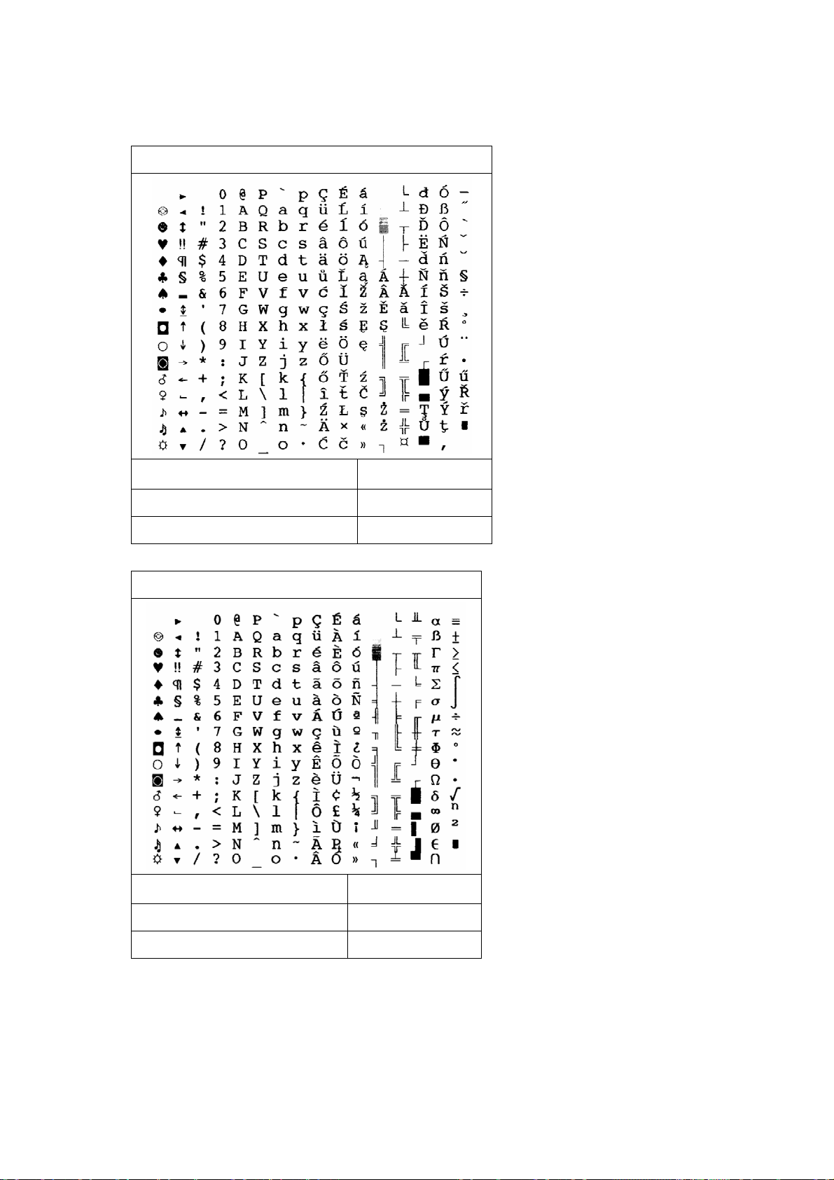
PC-852 (= P852)
( 17 U
ASCII:
E
c
Decimal: 27 40 49 55 85
Hexadecimal: 1B 28 31 37 55
PC-860 (= P860)
( 20 U
ASCII:
E
c
Decimal: 27 40 50 48 85
Hexadecimal: 1B 28 32 30 55
86
Page 90
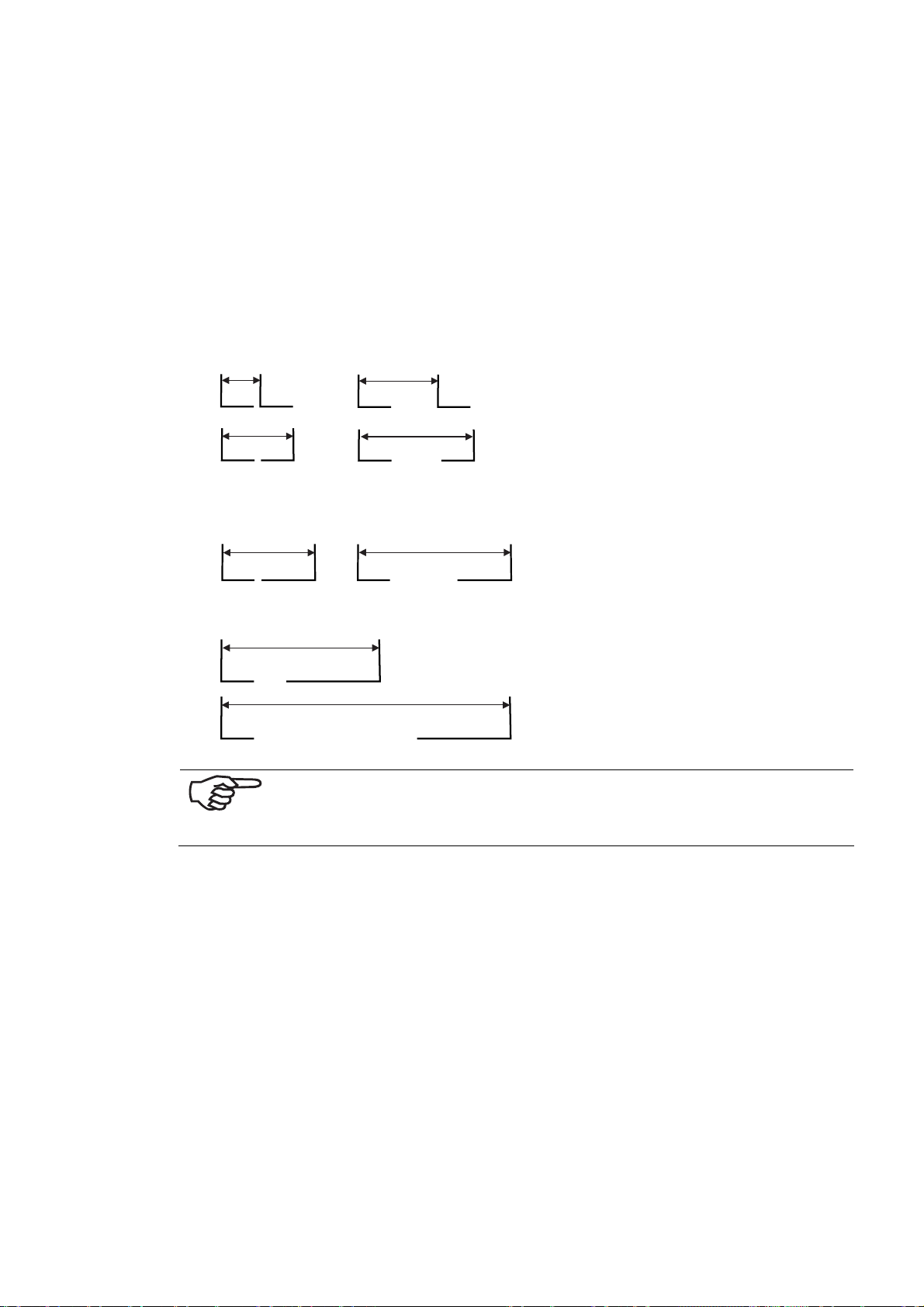
8.5 Side Guide
• Side guide short (2x) (standard)
• Side guide middle (standard)
• Side guide long (accessory)
Adjustable width of the Side guide
The data (in mm/inches) refers to the print object width crosswise to the transport
direction.
• Rear + frontal side guides, short x 2
85
3.35
142
5.6
125
5
• Rear side guide, short+
Frontal side guide, middle
198
7.8
• Rear side guide, short+
Frontal side guide, long
277
10.9
365
14.37
When using the corresponding maximum possible width of the adjustable side guide, there remains an unprintable margin of 15 mm
(0.6 inch) from the rear side guide.
225
8.86
285
11.2
87
Page 91
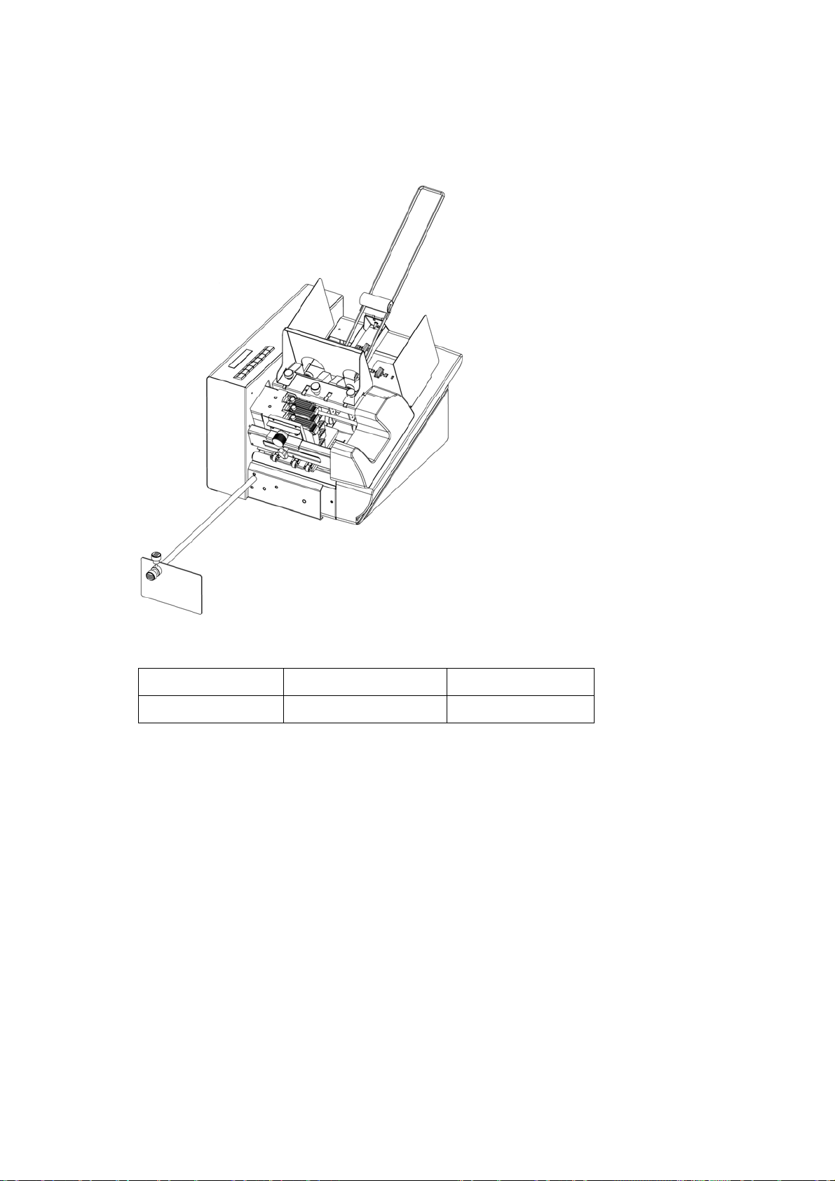
8.6 Accessories
The following accessories are available (must be purchased separately):
Illustration 8-11: Divert mechanism
Pos. Description Pieces
1 Divert mechanism 1
The divert mechanism changes the transport direction of the ejected print object
90° on the conveyor belt.
88
Page 92

8.7 Technical Data
Throughput For Printer 830: max. 11,000 postcards /hour at 1x3, 1x6
For Printer 930: max. 39,000 post cards /hour at 1x3, 1x6
Printheads 3
Printing speed For the Printer 830: 0.54 m/s
For the Printer 930: Minimum 0.15 m/s
Maximum 1.84 m/s
Throughput For the Printer 830:
Postcards (A6) 11,000 pcs./hr
C5/C6 9,000 pcs./hr
For the Printer 930: at 6x6 at 1x3
Postcards (A6) 14,000 pcs./hr 39.000 pcs./hr
C5/C6 9,000 pcs./hr 26.000 pcs./hr
Printing process Fixed-Head (fixed printhead) manual positioning
Graphics capabilities YES
Colors up to 3, Spot Color
Print object formats Minimum (L x W): 135 x 70 mm
Maximum (L x W): 500 x 352 mm
Print height max. 38 mm per unit / 9 lines Courier 12
Print width max. 500 mm
Material thickness For the Printer 830: Minimum 0.10 mm
Maximum 2 mm
For the Printer 930: Minimum 0.10 mm
Maximum 6.35 mm / ¼“
Thickness difference Maximum 1 mm – depending on the material
Paper capacity Maximum 350 pcs. / 170 mm / 1 kg
Types of paper Single sheets, documents, envelopes, booklets etc.
Paper quality Inkjet compatible, no foils or high-gloss paper
Print qualities 1x3, 1x6, 2x3, 2x6, 3x3, 3x6, 6x3, 6x6
Ink Cartridge HP45A or HP1918 cartridge
Character sets 13 resident and downloadable fonts
Operating noise The emission value for the place of operation is < 70 db (A) in
Main memory 64 MB
Address storage The last 20 pages
Mains voltage 100 - 240VAC at 50 ~ 60Hz
Operating range 10-31°C / 20-80% rel. humidity
Status interfaces USB (1.1) / Parallel Centronics Std. (IEEE1284)
Status interfaces Serial (RS-232)
Driver Windows 3.1 / NT / 2000 / XP
Special functions Barcodes (10 resident barcodes)
Dimensions (L x W x H) 425 x 380 x 280 mm
Weight 22 kg
L = in transport direction
2
1 m distance, measured in accordance with ISO 9296.
(no condensation)
Configuration memory for 9 user settings
Loadable test address
Ink consumption display
2
Possible with suitable inks and drying systems
89
Page 93
9 Glossary
ASCll: ASCll is the abbreviation for "American Standard Code for Informa-
tion Interchange". The printer commands used in this manual have
been entered with ASCII characters. Decimal and hexadecimal characters can also be used.
Barcode: Data for a print object is converted to a one-line, language- and
symbol-neutral barcode. A barcode is easy to create, and it is readable with simple opto-electronic devices. It is also additionally
printed for the plain text information.
Baud rate: The baud rate is the speed at which the data between the computer
and printer is transferred on the serial interface. The computer and
printer must have the same baud rate. This can lie between 1200
and 9600 baud, depending on the computer that is used. The baud
rate is only set, when using a serial interface.
Bit: Binary digit. As the smallest unit of digital information, a bit is rep-
resented by only two positions: "1" or "0".
Bitmap: A bitmap represents a collection of dots as a graphic or text graphic
in output devices (printer, monitor).
Buffer: The buffer is a storage area of the printer. Certain input and output
data is stored here until further processing.
Byte: A storage unit, consisting of 8 bits.
Carriage: The printhead is fixed to a movable carriage.
Character
height:
Character sets: A character set is application-specific defined and is usually a collec-
Character
density:
Character
spacing
Character: A character is understood to mean letters, numbers and symbols
Character height refers to the height of a printed capital letter. It is
measured in pica points. A point is 1/72 of an inch.
tion of letters, numbers, lines and symbols within a font. Character
sets can also be made up purely of symbols.
Character density (pitch) refers to the number of printed characters
within an inch.
All fonts have either constant or variable character spacing In a font
with constant character spacing, all characters have the same width
space, regardless of their size. In the case of proportional fonts, the
width space is determined by the width of the character in question.
that can be printed.
Configuration: In a configuration, certain printer settings can be stored. You can
set up several configurations, and store each of them under an individual configuration number.
Control code: For control code, see printer commands.
Control panel: The control panel comprises the keyboard and display. Settings for
this are carried out internally on the printer.
CPl: CPI (= Characters Per Inch) is the measuring unit for characters per
90
Page 94
inch for the in character density.
Data transfer: Data transfer is the transfer of information between the computer
and the printer.
Character size: The character size is measured in pica points. A point is 1/72 of an
inch.
DPl: DPI (= Dots Per Inch) is the measuring unit of dots per inch for the
image definition. The more dots there are, the higher the definition.
Driver: For driver, see printer driver.
Escape
character:
Escape
sequences:
Factory
configuration:
Font cassettes: They contain fonts that can be loaded in the printer.
Font slant: The characters can either be printed standing straight (normal) or -
Font: A font is a collection of characters and symbols with the same type-
Handshake: Handshake is the control of the data transfer between the computer
The escape character Ec is a beginning of a command in ASCII code.
This character is not printed; the printer recognizes the following
character as a command code.
For escape sequences, see printer commands.
The printer is programmed - prior to shipping - with standard settings. These settings are stored in configuration "0", and they remain active until another configuration number is selected and the
setting changes are carried out.
at a constant angle - standing slanted (italic).
face, spacing, size (height), line width and font slant. Fonts can be
installed as resident fonts in the printer, or they can be loaded externally from font cassettes.
and the printer, in order to prevent overflow or loss of data in the
printer buffer.
Hardware: Hardware describes the components of your computer system, such
as computer, keyboard and printer.
Ink Cartridge: The ink cartridge contains the ink for printing. After it has been used
up, the empty cartridge is replaced by a new, commercially available
one.
Interface cable: This is the data transmission cable that connects your computer with
the printer or other peripherals.
Interface
connector
socket:
Line width: The line width refers to the width of the character line. There are
Loadable fonts: Loadable fonts (soft or download fonts) are saved on disks. They
The PRINTER 700/710 is shipped with three interface connector
sockets (USB, parallel and serial). These are located at the rear side
of the machine over the power supply plug. The connector cable for
your computer and printer are connected here.
normal and bold line widths
can be transferred to the printer memory.
91
Page 95
LPI: LPI (= Lines Per Inch) is a unit measuring lines per inch for the ver-
tical line spacing. Printing is most frequently in 6 lpi line spacing.
Offline: In the offline condition, the printer cannot receive data from the
computer. In this condition, settings and programming are carried
out on the printer itself.
Online: In the online condition, the printer is able to receive data from the
computer. In this condition, the keyboard in inactive, with the exception of the "START" key.
Paper jam: A paper jam exists when the paper gets stuck during the printout,
thereby blocking the feeder or output.
Paper Size: Paper Size refers to the paper format that will be printed. With a
rotation of the address block of 180°, the top margin value is automatically calculated, so that the set value corresponds to the normal
direction of the address block.
Paper
recognition:
Parallel
interface:
Parity: Parity is an error detection technique that is used with a serial inter-
PCL command: PCL (= Printer Control Language) is the HP PCL Level 5 printer lan-
Pitch: For pitch, see character density.
Printer driver: The printer driver converts the printer commands entered via the
Printer
command:
Printhead gap: The printhead gap influences the sharpness of the print. Too large a
Paper recognition is necessary for maintaining the top margin value
and for stopping the printer in the event of paper jams. In each
case, the print object must be transported via the paper recognition.
The parallel interface, also referred to as the Centronics interface, is
a connection of the computer to the printer. During this process,
8 Bits = 1 Byte are/is always transferred at one time (parallel).
face. Errors in transfer are recognized during data transfer. Here the
even number of the binary 1 is checked in an item unit (e.g. a byte).
guage developed by Hewlett-Packard.
software into command codes for the printer. The printer driver
must be adapted to the software, as well as to the printer.
The printer command is entered via the software, in order to carry
out changes in the active printer configuration.
gap causes a blurred print; too small a gap can smudge the ink.
Printhead
holder:
Printing area: The printing area comprises the maximum width that is reachable
Resident fonts: The installed fonts (resident fonts) have been installed in the
Resolution: A measurement of image definition. It is measured in dots per inch
Sans serif font: This is a font-family that has no line running horizontal ("feet") on
The printhead holder keeps the ink cartridge in position.
for the ink cartridge.
printer. They are a fixed component of the printer.
(dpi = dots per inch).
the head or foot of a letter. This text, for example, is printed in a
92
Page 96
"sans serif" font.
Serial interface: With a serial interface, the data is sequentially transferred (bit by
bit), from the computer to the printer. The connection is made by a
RS-232-C socket.
Serif font: Serifs are "feet" on Bodoni book type. The typeface Cour is a "serif"
font, for example.
Setting: Selection of preset configurations.
Soft Font: Soft fonts (loadable fonts) are fonts that are stored on disks. These
fonts can be transferred to the printer memory.
Software: Software is the machine-language and graphics programs, pro-
gramming or other special application packages installed on your
computer.
Separating finger:
Typeface: Typeface refers to the print design of a character set. Cour, for ex-
The separating finger makes it possible to feed individual sheets
from a stack of sheets. The upper sheet is separated from the rest
of the stack.
ample, has a character design different from LetGot or Helv.
93
Page 97

10 Index
Barcode................................ 56, 65, 90
Baud Rate........................................ 90
CARTR. RESET.................................. 36
Character Density .................. 72, 90, 92
Character Height.......................... 73, 90
Character Set................... 75, 76, 77, 90
Character Spacing............. 71, 72, 73, 90
Connector Socket.........................67, 69
Control Panel.................................... 90
Driver................... 24, 25, 26, 30, 31, 91
Factory Setting................................. 60
Firmware ....................................63, 64
Font..................................... 65, 91, 93
Handshake....................................... 91
Initialization..................................... 61
Ink Cartridge.................... 32, 33, 91, 92
Interface.......................................... 67
Interface Connector Sockets .....66, 91
Left Margin....................................... 65
Offline Mode.....................18, 20, 42, 61
Orientation....................................... 74
Paper Run without Printing ................. 21
Paper Size........................................ 92
Parity .............................................. 92
Plug Assignment ............................... 70
Print Density..................................... 71
Print Gap ......................................... 21
Printhead Gap................................... 92
Programming Mode ......................60, 61
Sans Serif ............................. 71, 77, 92
Serif Typeface........................ 71, 76, 77
SETTING..........................59, 60, 61, 93
Test Print................... 21, 43, 58, 76, 77
Top Margin....................................... 92
USB Driver....................................... 26
94
 Loading...