

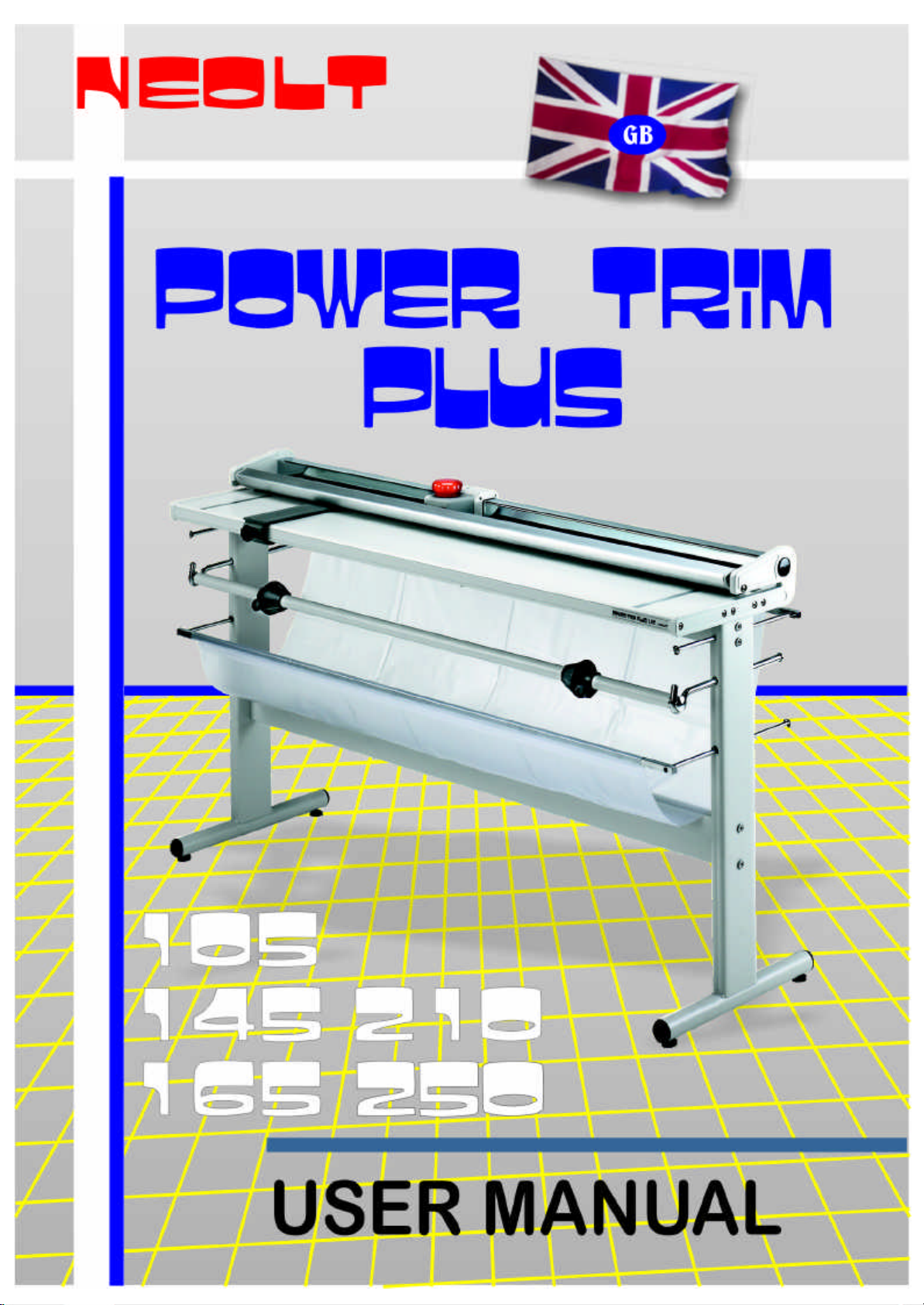
Neolt Power Trim Plus 105, Power Trim Plus 145, Power Trim Plus 210, Power Trim Plus 250, Power Trim Plus 165 User Manual
Page 1
Page 2

power trim plus
105 / 145 / 165 / 210 / 250
USER’S MANUAL
ENGLISH Cod. NLT.QN-A-C-MM-3-1S-GB NEOLT
USOGB-PWTP -1S.DOC 2003
Page 3

CONTENTS
SECTOR:
DATE:
q
q VERSION: PWTP-01-01/2003 q AUTHOR: POLENI P.
POWER TRIM PLUS q
12/01/2003
Chapter 1 General information ..................................................................................... 1
1.1 Data of the manual .................................................................................. 1-1
1.2 Users....................................................................................................... 1-1
1.3 Property of the information...................................................................... 1-1
1.4 Conventions used.................................................................................... 1-2
1.4.1 Conventional terms used .............................................................. 1-2
1.4.2 Conventional symbols used.......................................................... 1-2
1.5 Identification data of the manufacturer.................................................... 1-3
1.6 Identification data of the machine............................................................ 1-3
1.7 Warranty.................................................................................................. 1-4
1.8 Assistance .............................................................................................. 1-4
1.9 Use of the manual ................................................................................... 1-4
1.10 Description of the machine ................................................................... 1-5
1.10.1 Correct use of the machine......................................................... 1-5
1.10.2 Incorrect use of the machine....................................................... 1-5
1.10.3 Structure of the machine ............................................................ 1-6
NEOLT
Chapter 2 Safety information........................................................................................ 2
2.1 Safety criteria........................................................................................... 2-1
2.2 Qualifications of the personnel ............................................................... 2-2
2.3 Responsibility........................................................................................... 2-2
2.4 Danger zones and residual risks............................................................. 2-3
Chapter 3 Characteristics of the machine................................................................... 3
3.1 Tecnical information................................................................................. 3-1
3.2 Machine performances............................................................................ 3-1
3.3 List of materials........................................................................................ 3-2
Chapter 4 Installation ..................................................................................................... 4
4.1 Qualification of the operator..................................................................... 4-1
4.2 Transport.................................................................................................. 4-1
4.2.1 Transport conditions...................................................................... 4-1
4.2.2 Assessment of damages during transportation............................ 4-2
4.3 Assembling.............................................................................................. 4-3
4.4 Adjustments............................................................................................. 4-6
4.5 Storage .................................................................................................... 4-7
4.5.1 Features ........................................................................................ 4-7
4.6 Positioning ............................................................................................... 4-8
4.6.1 Characteristics of the area of installation ..................................... 4-8
4.6.2 Testing .......................................................................................... 4-8
Power trim plus
i
Page 4

CONTENTS
Chapter 5 Use ................................................................................................................. 5
5.1 Qualification of the operator..................................................................... 5-1
5.1.1 Working place................................................................................ 5-1
5.1.2 Insertion of the media to be cut..................................................... 5-1
5.1.3 Characteristics of the media to be cut........................................... 5-2
Chapter 6 Maintenance.................................................................................................. 6
6.1 Routine maintenance............................................................................... 6-1
6.1.1 Qualification of the operator........................................................... 6-1
6.1.2 Procedure...................................................................................... 6-1
6.2 Extraordinary maintenance..................................................................... 6-1
NEOLT
Chapter 7 Demolition...................................................................................................... 7
7.1 Qualification of the operator..................................................................... 7-1
7.2 Deactivation of the machine.................................................................... 7-1
7.2.1 Procedure...................................................................................... 7-1
Chapter 8 List of attachments ..................................................................................... 8
Attachment A Optional roll holder ................................................................................ A
A.1 Assembly optional roll holder.................................................................. A-1
Attachment B Optional lamp for cutting area ............................................................... B
B.1 Assembly of cutting area lamp............................................................... B-1
Attachment T1 Technical Sheet ..................................................................... SCH-TEC
T1 Replacing rotating blade.............................................................. SCH-TEC-1
Power trim plus
ii
Page 5

GENERAL INFORMATION
Data of the manual 1.1
• Instruction manual. TRIMMER
• Code of the manual: NLT. QN-A-C-MM-3-1S-GB.
Users 1.2
Instruction manual.
• Transporter.
• Installer.
• User.
• Maintenance personnel.
• Demolition squad.
NEOLT
4 For further details on the users of this manual, see 2.2 Qualifications of the personnel.
Property of the information 1.3
The information contained in this manual is reserved property. All rights are reserved.
This manual cannot be reproduced or copied, as a whole or in parts, without prior written
consent of NEOLT S.p.A. These documents are provided only for the use of the client
whom the manual has been supplied to with the machine, and can be used only for the
installation, use and maintenace of the machine the manual refers to.
NEOLT S.p.A. states that the information of this manual is congruent to the technical and
safety requirements of the machine the manual refers to. The manufacturer cannot be held
responsible for any direct or indirect damages to people, objects or animals due to the use of
these documents or of the machine in conditions other than those authorized..
NEOLT S.p.A. reserves the right to change or improve, without notice, these documents
and these machines, and also other machines marketed of the same model as the one this
manual refers to but with a different serial number. The information of this manual
particularly refers to the machine specified in 1.6 Identification data of the machine.
.
Power trim plus
1-1
Page 6

GENERAL INFORMATION
Conventions 1.4
Conventional terms 1.4.1
Machine: indicates the machine specified in section 1.6 Identification data of the machine.
Frame: structure supporting the machine.
Qualified personnel: people, who thanks to their qualification, preparation and experience,
and thanks to the knowledge of the relevant rules, safety requirements and service norms,
are able to recognize and avoid any possible danger for the people, the material and the
machine.
The description of direction, sense and position (right side of the machine, left side of the
machine) refers to the operator standing in front of the machine.
Conventional symbols 1.4.2
Text in italic: indicates the title of a chapter, a section, a sub-section, a paragraph, a table, or
a figure of this manual or of another related publication.
1 (example of a generic number): symbolic representation of a command or signaling
device.
A (example of generic letter): symbolic representation of a part of the machine.
NEOLT
4 Notes contain important information, given outside the text to which they refer.
M The danger symbols indicate those procedures which, if not respected, could cause physical
damages to the operator. The manufacturer cannot be held responsible for any damages to
people due to noncompliance with these norms.
& The warning symbols indicate those procedures which, if not respected, could damage the
machines or the devices connected to it. The manufacturer cannot be held responsible for
any damages to objects due to the noncompliance with these norms.
Power trim plus
1-2
Page 7
GENERAL INFORMATION
ITALY
Identification data of the manufacturer 1.5
neolt S.p.A.
Via G. Galilei, 8
24036 Ponte San Pietro (BG) - ITALY
Tel. 035/468811
Fax 035/468886
http://www.neolt.it
E-mail.: [email protected]
NEOLT
Identification data of the machine 1.6
Name
TRIMMER
Model POWER TRIM
plus
Serial number
Year of construction
Neolt
Power trim plus
1-3
Page 8
GENERAL INFORMATION
Warranty 1.7
NEOLT S.p.A. warranty covers the machine for one year.
The parts subject to normal wear and tear are not included in the warranty. The warranty is
limited to the substitution or repair of the parts that should result damaged or defected.
The assessment of the defects and causes is carried out at NEOLT S.p.A. facilities.
The warranty is cancelled if the machine is used incorrectly, or in an improper or excessive
way, if any non-original spare parts are used and for noncompliance with the norms of this
manual.
In no case can the purchaser demand the resolution of the contract, claim for damages or
the extension of the warranty.
NEOLT
4 NEOLT S.p.A. cannot be held responsible for any negative advertisement, or loss of
earnings, due to technical or mechanical malfunctioning of the product in use or in
display.
Service 1.8
NEOLT S.p.A. provides, on request, assistanc e for the installation and the maintenance
of the machine.
Use of this manual 1.9
Carefully read the chapters General information, Safety information, Characteristics of the
machine and Operator interface .
4 Please consult the relative chapter for any transportation, installation, use, maintenance and
demolition operation.
This manual and the attached documentation must be kept for the entire technical life of the
machine in order to consult it quickly when necessary.
If the machine is sold as second-hand, this manual and the attached documentation must be
supplied along with the product.
Power trim plus
1-4
Page 9

GENERAL INFORMATION
Description of the machine 1.10
Correct use of the machine 1.10.1
This machine can be used only to cut media having the allowed basic weight (max paper
thickness 2,2 mm).
As the machine consists of assemblies physically separated and autonomous, the proper
use of the machine can be identified also in the operation of a single part.
Foreseen modes of use
The installation and the extraordinary maintenance of the machine must be carried out by
qualified personnel only.
The machine has been designed to be used in a site having the following features:
• Protection against atmospheric agents.
• Proper illumination.
• Allowed range of temperature: from 18°C to 35°C.
• Allowed humidity range: from 30 % to 80 %.
Incorrect use of the machine 1.10.2
Any use other than that indicated in Section 1.10.1 Correct use of the machine is to be
considered incorrect, especially:
• Using the machine in ways which differ from those which it has been designed for,
represents an anomalous condition and could therefore damage the structure of the
machine.
• Using the machine without its protections and without the safety equipment.
• The non compliance with the procedures described in this manual, and specially those
concerning maintenance and repairing.
• The use of the machine in a site where fire and explosion risks are present, as the
machine is not provided with explosion proof devices.
• Its use in an explosive environment.
• Its use in an inflammable environment.
NEOLT
Power trim plus
1-5
Page 10
GENERAL INFORMATION
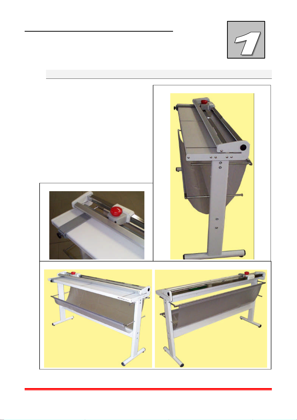
Fig. 1.1 Lateral View
Fig. 1. 2 Detail
Fig. 1. 3
Prospect views
E
D
B
Structure of the machine 1.10.3
The machine is composed of the
following parts:
A Work surface
B Support
C Paper collector curtain
NEOLT
D Containment bracket
E Blade holder carriage
A
F
F Sliding bar
C
Power trim plus
1-6
Page 11

INFORMATION ON
SAFETY
Safety criteria 2.1
During designing and manufacturing of this machine, all criteria and care in order to satisfy
the essential safety requirements foreseen by the relevant rules have been taken into
account.
The accurate evaluation of the risks performed by the manufacturer has allowed to eliminate
most of the risks concerning the usage conditions of the machine, both foreseen and
reasonably foreseeable.
The complete documentation including all the safety norms adopted is in the technical
booklet of the machine, which is deposited at the manufacturer's premises.
The manufacturer recommends strict compliance with the instructions, procedures and
recommendations of this manual and with the laws in force on the safety in the work plac e.
This also refers to the use of the protection devices foreseen, both those integrated in the
machine and personal.
NEOLT
4 NEOLT S.p.A. cannot be held responsible for any damages to people, pets or objects due to
noncompliance with the safety rules and the recommendations contained in the
supplied documentation.
Power trim plus
2-1
Page 12
INFORMATION ON
SAFETY
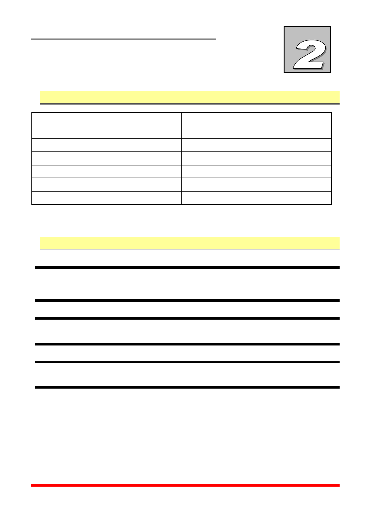
Personnel qualification 2.2
Stage of the technical life of the machine Qualification of the operator in charge
Transport Qualified transportation
Installation Qualified personnel
Use Qualified personnel
Routine maintenance Qualified personnel
Extraordinary maintenance Engineers authorized by NEOLT S.p.A .
Demolition Qualified personnel
NEOLT
Protections 2.3
4 NEOLT S.p.A. cannot be held responsible for any damages to people, pets or objects due to
noncompliance with the safety rules and the recommendations contained in the
supplied documentation.
M Tampering with the protections and the safety devices is dangerous for the people using the
machine and for those exposed to it.
4 NEOLT S.p.A. cannot be held responsible for any damages to people, animals or objects
due to tampering with the protections.
Power trim plus
2-2
Page 13
INFORMATION ON
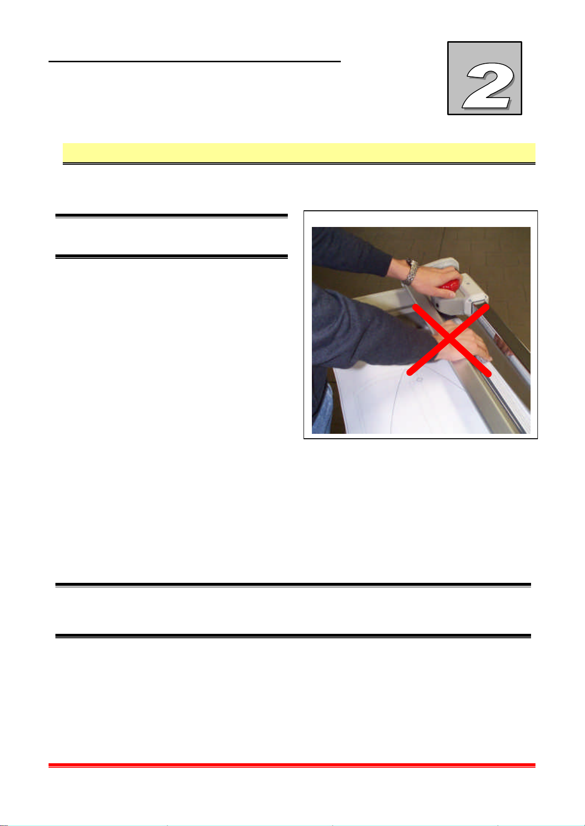
Fig. 2. 1 Cutting zone
SAFETY
Dangerous area and residual risks 2.4
All the areas around the machine in which people are at risk of injuries or health problems
are considered dangerous.
M Pay close attention to hands when the
cutting operations.
During certain intervention procedures
on the machine, which are pointed out
each time in this manual, residual risks
for the operator may arise. Residual
risks can be avoided by carefully
complying with the procedures of this
manual and using the personal
protection devices indicated, such as:
• Maintenance and service operations
must be carried out only by the
engineers authorized by the
manufacturer.
• Paying attention to the danger
notices on the trimmer.
NEOLT
4 NEOLT S.p.A. cannot be held responsible for any damages to people, animals or objects
due to noncompliance with the norms or avoidance in using the prescibed individual protection
devices (IPD).
Power trim plus
2-3
Page 14

INFORMATION ON
SAFETY
NEOLT
Power trim plus
2-4
Page 15
CHARACTERISTICS OF
THE MACHINE
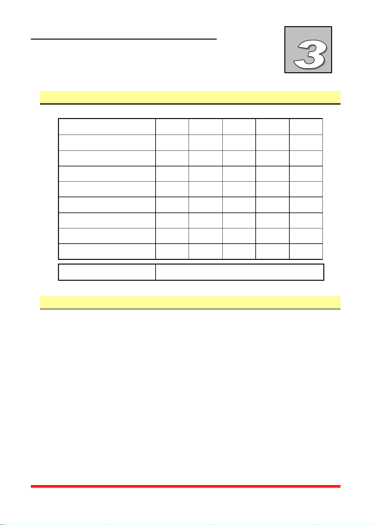
Technical specifications 3.1
NEOLT
MODEL 105 145 165 210 250
Max. cutting thickness (mm)
2,2 2,2 2,2 2,2 2,2
Usable cutting length (cm) 105 145 165 210 250
Length (cm) 128. 168 189 232 274
Width (cm) 39 39 39 39 39
Height (with holder) (cm) 95 95 95 95 95
Height of working table (cm) 87 87 87 87 87
Trim weight (kg) 20 26 28 30 34
Support weight (kg) 16 20 22 26 28
Accessori Roll holder – cutting area lamp
Performances 3.2
q Max. cutting thickness 2,2 mm
Power trim plus
3-1
Page 16
CHARACTERISTICS OF
THE MACHINE
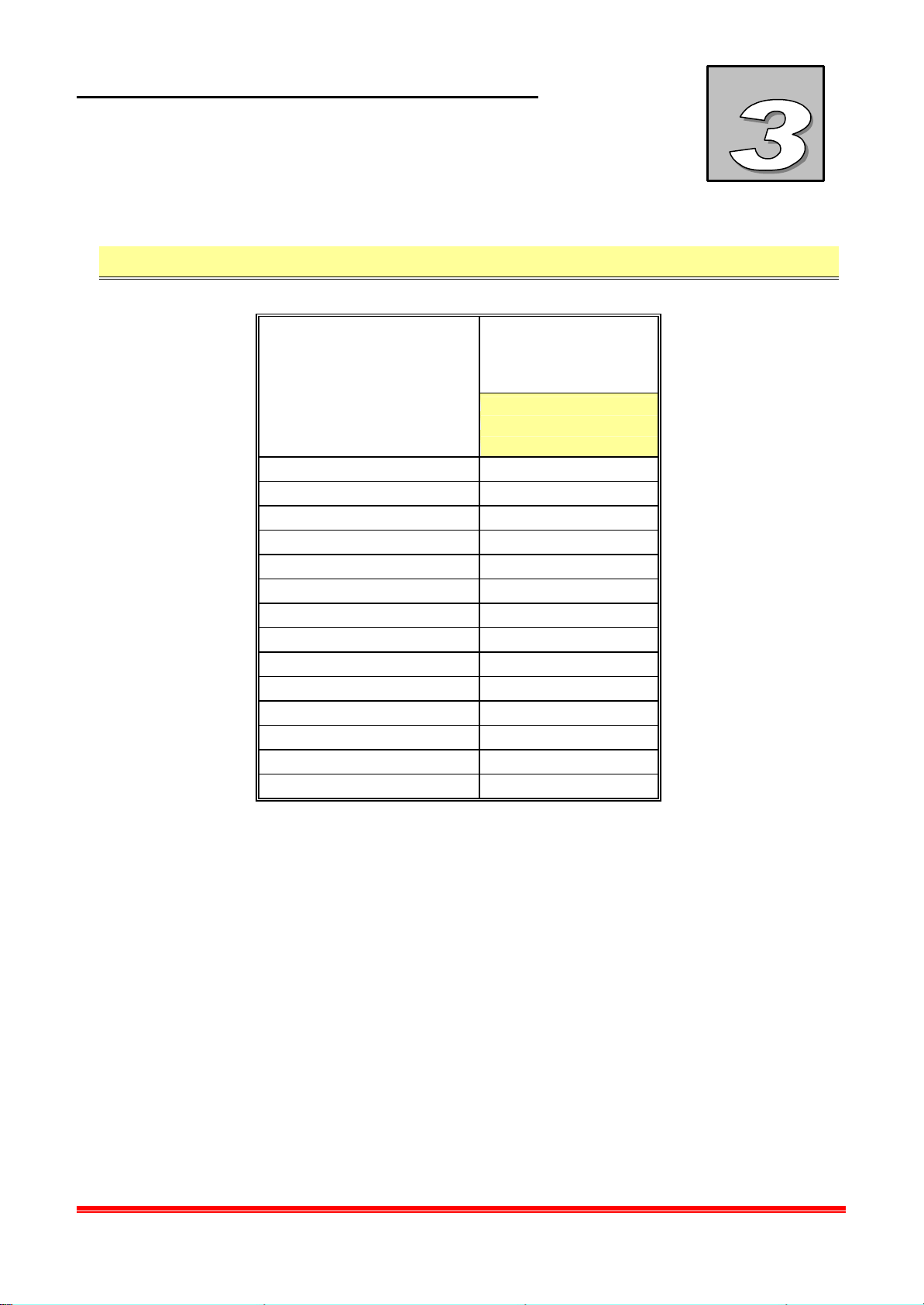
List of media 3.3
Media
Drawing paper
Cardboard
Cibachrome
Slides
Acrylic film
Hot sealing film
Carton
Paper
Photographic film
Photographic paper
Polypropylene film
Fabric
Jute
power
TRIM plus
Max. cutting thickness
2,2 mm
X
X
X
X
X
X
X
X
X
X
X
X
X
NEOLT
Power trim plus
3-2
Page 17
INSTALLATION
Qualification of the operator 4.1
Transport, installation and connection operations must be performed only by personnel
qualified in transportation and electrical operations.
Transport 4.2
Transport condi tions 4.2.1
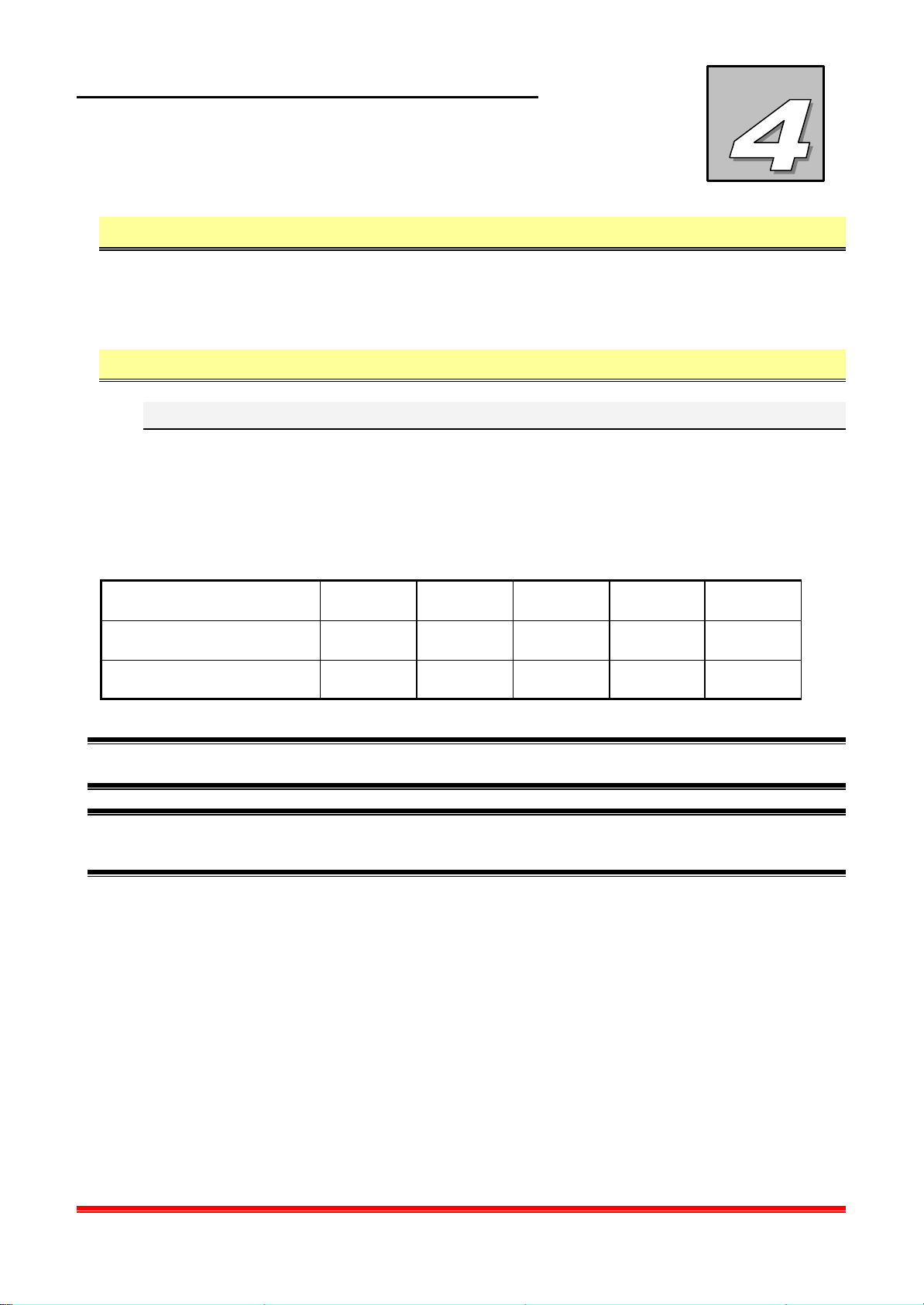
The trimmer is shipped with a packaging consisting of three cardboards 1 for components
protection, and of a carton box 2 containing all the components. Fig. 5.1 Transport
conditions.
The packaging size and its gross weight (trimmer plus pack aging) are the following:
NEOLT
MODEL 105 145 165 210 250
Size (WxDxH - cm) 120x51x30 186x51x30 230x51x30 280x51x30 280x51x30
Weight (gross) - Kg
46 50 55 58 70
M Please use suitable lifting devices and accessories, complying to the rules in force.
4 To avoid shocks and turnover, apply the needed care. Protect the machine against external
atmospheric agents.
Power trim plus
4-1
Page 18

INSTALLATION
Fig. 4.1
Transport conditions
1
Assessment of damages during transportation 4.2.2
Check the conditions of the machine by visually inspecting it, after having removed it from
the shipping box. Any defects on the visible parts of the machine indicate crashes during
transportation, which could also affect the ordinary operation of the machine.
In general, check screws and bolts for tightness.
NEOLT
2
Power trim plus
4-2
Page 19
INSTALLATION
NEOLT
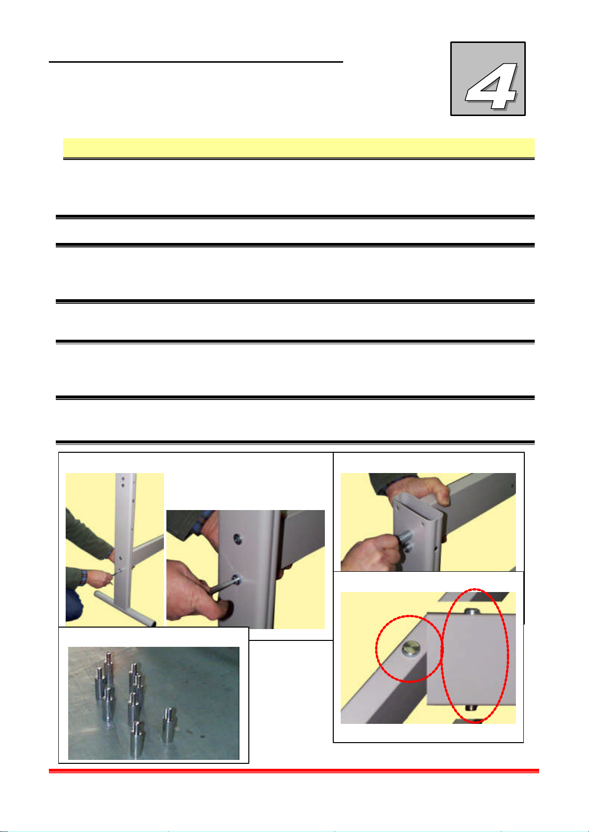
Assembly 4.3
• Open the packaging box 1 which contains all parts (Fig. 4.1 Transportation conditions).
• Remove the polyester protections 2 (Fig. 4.1 Transportation conditions)
& This operation must be carried out by minimum two people.
• Screw on the lowe r cross-bar 3 first to one shoulder, then to the other with the supplied
screws and nuts 5 to assemble the support.
& Attention the shoulder has holes of different diameter, the side with the bigger holes must
face outwards.
• Screw on the upper cross bar 4 to the shoulders following the procedure of the lower cross
bar, using the supplied screws and nuts 5.
& Attention when you position the upper cross bar, make sure the central pin is facing upward
6. The calibration set by Neolt is equal to 3 mm.
3
5
4
6
Power trim plus
4-3
Page 20
INSTALLATION
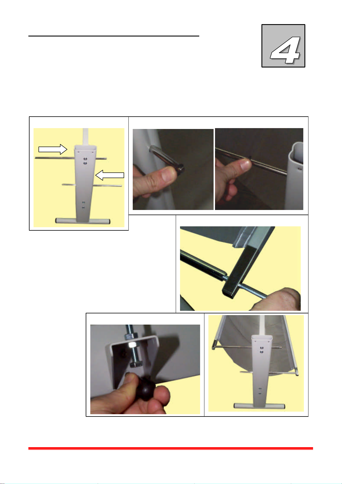
• To assemble the paper collection basket, first slide in the basket holding bars in front
(bottom) 7 and then back (top), and lock in the shoulder with two Benzing rings per bar 8, in
the appropriate seats.
7
• Slide the square bars in the appropriate
holes on the two sides of the basket.
• Screw on the two square rods to the
basket holding rods previously positioned
9.
• Avvitare i due supporti per il piano nella
Screw on the two supports for the table in
the front part on the upper cross bar using
the two supplied screws 10 .
10
NEOLT
front back
8
9
front back
Power trim plus
4-4
Page 21
INSTALLATION
NEOLT
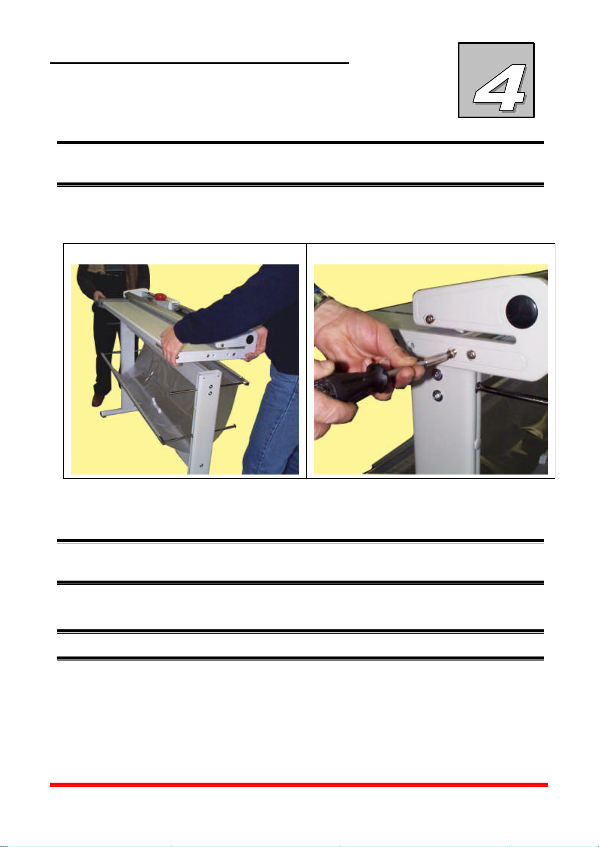
M As the trimmer is vary heavy, wear proper working gloves, and remember that for this
operation minimum four persons are required.
• Position the cutter on the assembled frame 11 and fix it to this with the screws in
equipment (2 for side) 12.
12 11
& During this operation move the work surface of the trimmer, for facilitate the fixing to the
frame.
• The trimmer is ready to start for the operative phase.
4 No other adjustments are necessary because the machine is factory tested before shipment.
Power trim plus
4-5
Page 22
INSTALLATION
Adjustments 4.4
The trimmer should not require any special adjustments, however we suggest checking two
options that could be slightly different, due to the final area of installation of the trimmer.
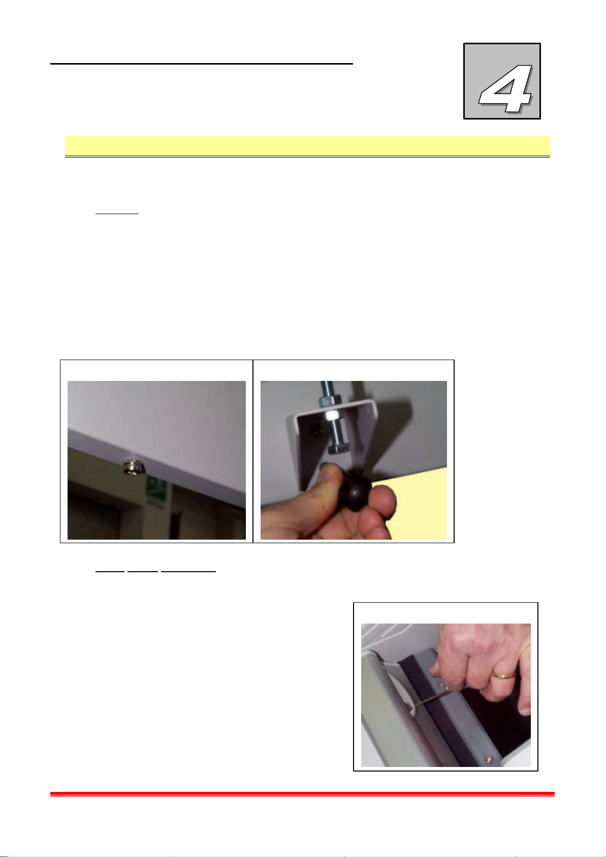
Planarity
The first thing to check is the planarity of the work table, that could change, due to
differences in level of the floor. To adjust the planarity of the work table follow this
procedure:
• Position the profile of the rigid media with a well trimmed side on the table of the trimmer.
• Check the parallelism between the table and the profile of the rigid material by using the
pin in the center of the cross bar of the upper work table 13. Screw to lower the table,
unscrew to lift.
• Adjust the two supports under the table 14, by screwing or unscrewing the screws, after
13 14
reaching the desired position lock the screws with the two nuts.
Sheet holder adjustment
The second element to check is the height of the Plexiglas sheet holder when the carriage
is on the extreme right or left. Follow this procedure to remove the trimmed material:
• Slide the Allen wrench in the hole of the
15
transparent sheet holder lifting slot 15 and
screw on to reduce the height, unscrew to
increase the height.
NEOLT
Power trim plus
4-6
Page 23

INSTALLATION
Storage 4.5
The instructions contained in this section should be respected during temporary storage
periods, which could occur in the following situations:
• Installation of the machine delayed with respect of the delivery date.
• Deactivation of the machine and consequent storage while waiting for a new installation.
Characteristics 4.5.1
• Temperature range allowed: from 5°C to 35°C
• Humidity range allowed: from 30 % to 80 %.
NEOLT
• Adequate artificial or natural illumination.
• Adequate protection against atmospheric agents.
• Sufficient clearance to perform the needed transport and lifting operations.
• Horizontal floor space capable to hold the weight of the machine.
• Sufficient clearance to perform the Routine maintenance and service operations.
Power trim plus
4-7
Page 24

INSTALLATION
Location 4.6
Characteristics of the location area 4.6.1
Space requirements
For the normal operation of the machine, loading and unloading operations included, the
needed space depends on the size of the media to be cut.
Protection against atmospheric agents
The machine must be placed indoor in a room protected from the direct contact wit the
atmospheric agents.
Floor requirements
Prepare an horizontal supporting plane where to install the machine, taking into account the
weight of the machine itself and of all the ancillary devices.
NEOLT
& Optimal stability condition ca be achieved with a maximum planarity error of ± … mm/m.
Illumination
For a proper operation and maintenance of the machine, a good illumination is required
(approximately 200 - 600 lux).
Environment features
• Allowed temperature from 18°C to 35°C
• Allowed relative humidity: from 30 % to 80 %.
Testing 4.6.2
Before attempting the normal and continuous operation of the machine, check its
appropriate general operation by performing some test cuts.
& In case of malfunctioning, find the reason for this and/or call technical NEOLT
assistance.
Power trim plus
4-8
Page 25
USE
Qualification of the operator 5.1
The machine must be used by qualified personnel only.
Workplace 5.1.1
Position of the operator: During start up and cutting, operator’s positing is in front of the
machine, with the control panel in the centre. In case of maintenance, his position depends
on the operation to be performed.
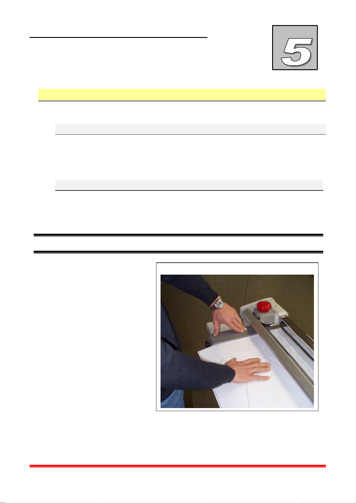
Feeding the media to cut 5.1.2
Follow the steps below to begin the process:
• Position the media to cut on the feeding table and by using the millimetric scales on the
table, measure the cut 1..
NEOLT
& If you need to cut very thick media, use the brackets B to prevent the media from sliding..
1
B
Power trim plus
5-1
Page 26
USE
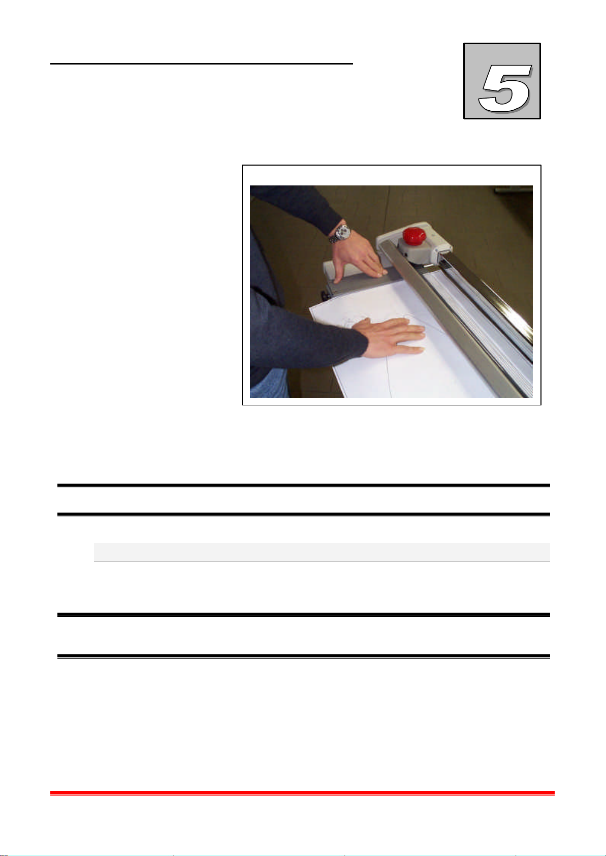
Execute the cut moving the carriage carry blade from right to left or vice versa 2.
2
• R Remove the spin part from the work surface and from the paper collector curtain the
cut part.
• Follow the above mentioned procedure to perform another cut.
NEOLT
& It is highly recommended not to lean against or put any object on feeding wings.
Characteristics of the media to cut 5.1.3
This trimmer was designed only to cut media with the weight indicated in this manual, see
media list chapter 3.3
& We recommend not to try to cut materials different form those which the machine has been
designed for. They could seriously damage the machine.
Power trim plus
5-2
Page 27
MAINTENANCE
Operation to be
Routine maintenance 6.1
M Untimely movements during maintenance. Be very careful.
Routine maintenance includes all the periodic and preventive operations enabling a safe use
of the machine.
Qualification of the operator 6.1.1
Routine maintenance must be carried put only by qualified personnel.
Procedure 6.1.2
Perform the periodical operations listed in the following table.
NEOLT
Frequency of
carried out
Dust removal. When necessary.
Removal of
waste material.
execution
When the waste
material accumulation
is excessive.
• Wipe the whole surface of the
machine with a wet cloth.
• With a vacuum cleaner or
compressed air. eliminate the
accumulated waste material.
Procedure Precautions
Do not use aggressive
products.
Ware working gloves.
Extraordinary maintenance 6.2
For any extraordinary maintenance operation not described in this manual, please contact
directly NEOLT S.p.A.
Power trim plus
6-1
Page 28

MAINTENANCE
NEOLT
Power trim plus
6-2
Page 29
DISMALTING
NEOLT
Qualification of the operator 7.1
The dismantling of the machine must be performed by qualified personnel.
Deactivation of the machine 7.2
Once the machine has reached the end of its technical and operating life, it must be deactivated.
The machine must be deactivated and put in the condition of not being used for the purposes
which it had originally been designed for. However, it must allow the reuse of the raw materials
which it was built with.
4 NEOLT S.p.A. cannot be held responsible for damages to people or pets due to the
reutilization of single parts of the machine for purposes or in situations different from
those which it has been designed for.
Procedure 7.2.1
• In case the machine has to be displaced, see section 5.2 Transport.
& The machine is made of non biodegradable materials. It must therefore be brought to an
authorized center for its disposal.
Power trim plus
7-1
Page 30

DISMALTING
NEOLT
Power trim plus
7-2
Page 31

ATTACHMENTS
Attachment 1 Assembly optional – roll holder
Attachment 2 Assembly optional – cutting area lamp
Attachment 3 Technical sheet – replacing rotating blade
Attachment 4 Part-list – exploded views
NEOLT
Power trim plus
8-1
Page 32

ATTACHMENTS
NEOLT
Power trim plus
8-2
Page 33
OPTIONAL
ROLL HOLDER
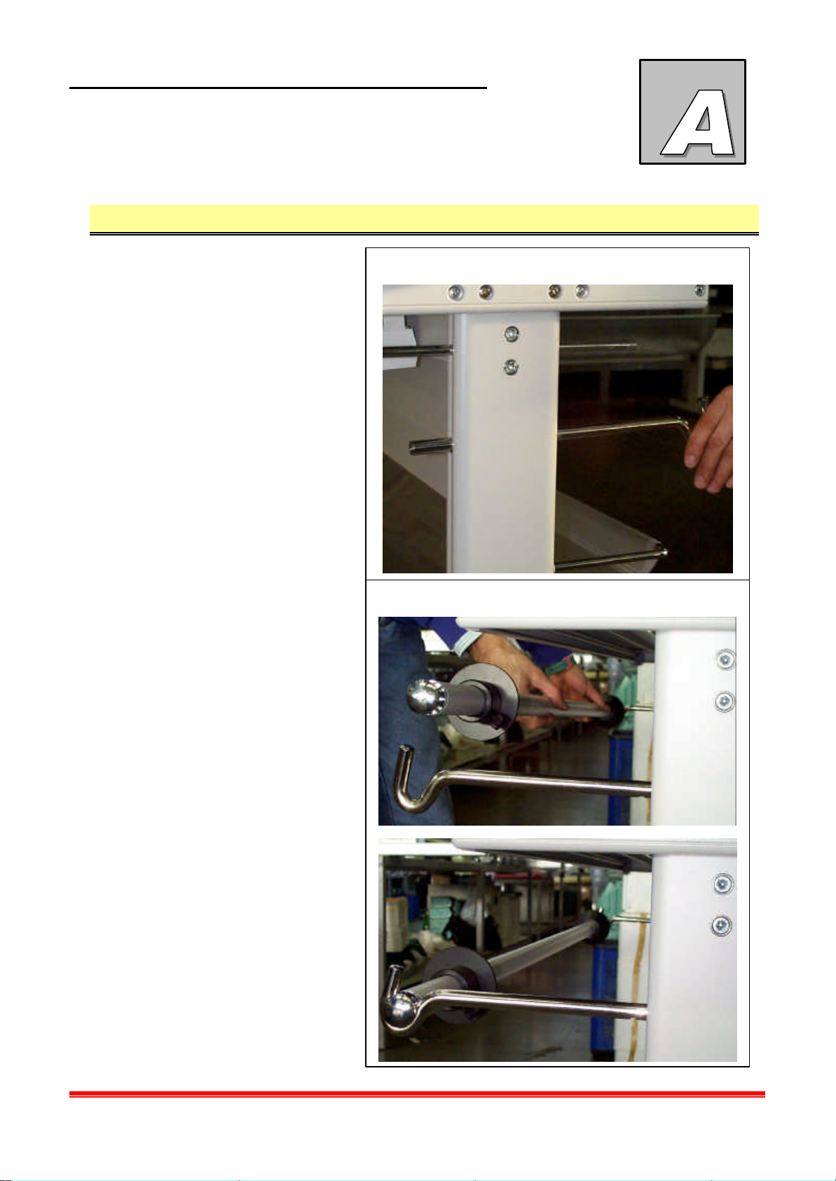
Assembly of optional roll holder A.1
Follow this procedure to
assemble the reel holder:
• Insert the reel holder
supports in the right and left
legs 1 and screw on the
proper screw in the back
part of the stand
• Insert the reel holder in the
seats of the stand that you
just assembled 2.
1
2
NEOLT
Power trim plus
A-1
Page 34

OPTIONAL
ROLL HOLDER
NEOLT
Power trim plus
A-2
Page 35
OPTIONAL
Fig. 1
Fig. 2
Fig. 3
NEOLT
CUTTING AREA LAMP
Assembly of cutting area lamp – optional B.1
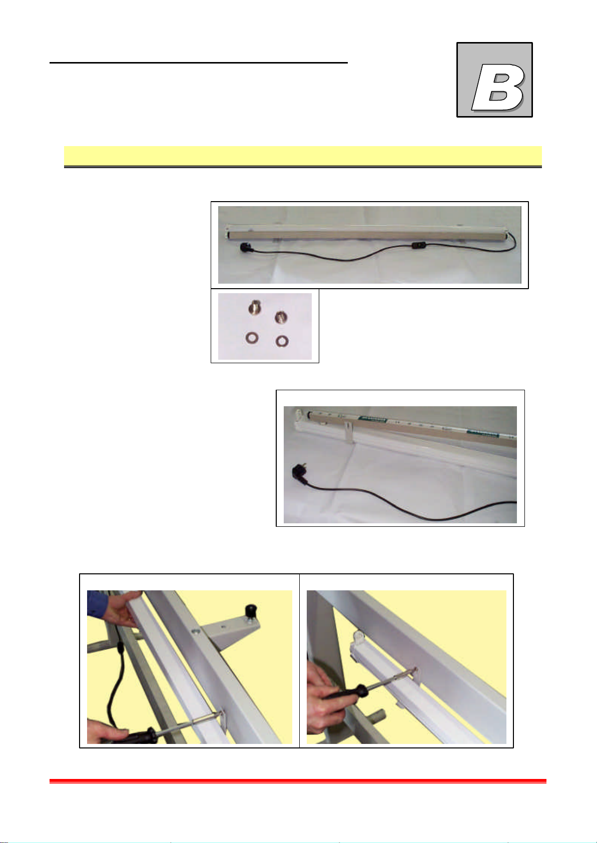
Follow this procedure to position the cutting area lamp:
• Remove the lamp from
the box and the bag with
the supplied screws
• Remove the lamp from the lamp holder. (Fig. 1).
• Assemble the ceiling lamp to the work table, by fastening the brackets already fixed on the lamp
to the threaded bushes on the upper cross bar in the back part of the table. (Fig. 2-3).
Power trim plus
B-1
Page 36
OPTIONAL
Fig. 4
Fig. 5
CUTTING AREA LAMP
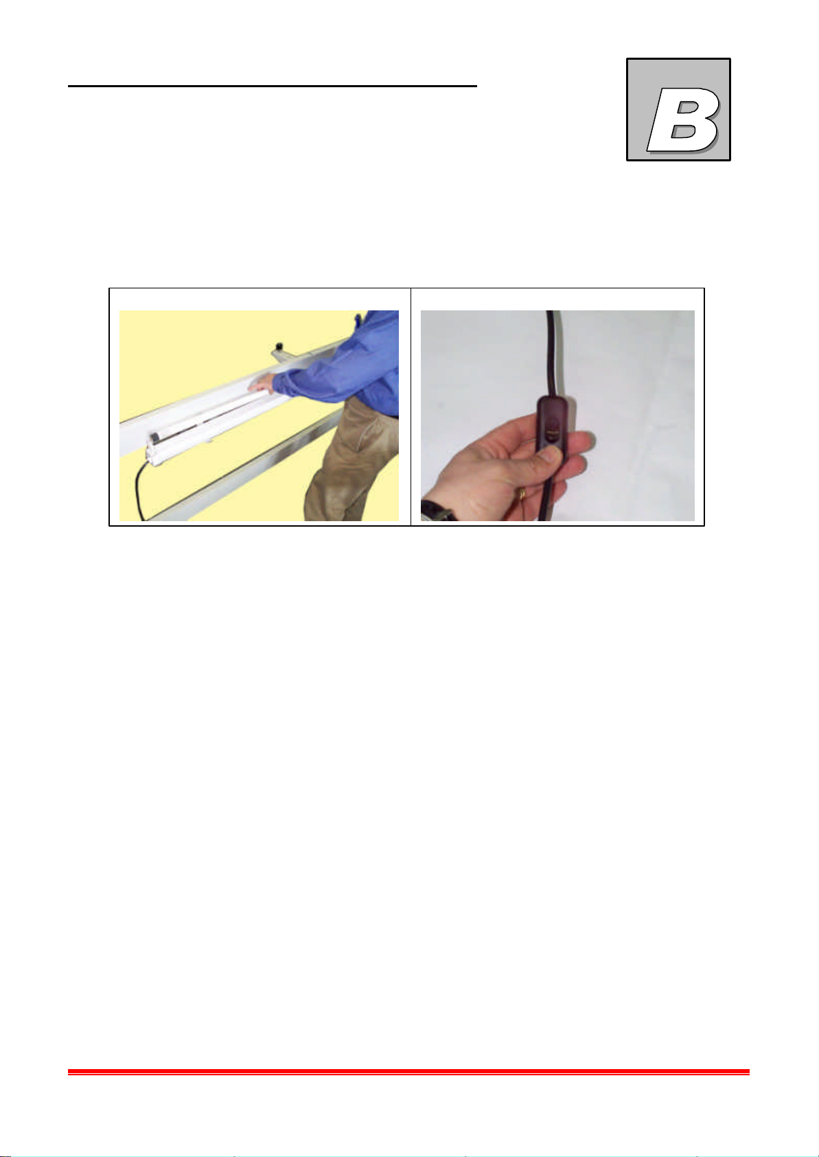
• Slide the lamp out of the protection box and insert it in the lamp holder on the ceiling lamp.
(Fig. 4).
• Connect the plug to an outlet and using the through switch on the connection wire switch the
lamp on and off (Fig. 5).
NEOLT
Power trim plus
B-2
Page 37
TECHNICAL SHEET
5 6
REPLACEMENT OF ROTATING
BLADE
Replacing the rotating blade
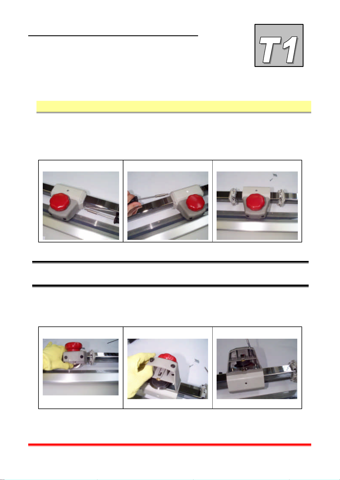
Follow this procedure to replace the rotating blade:
• Remove the screws that fix the two side plugs (two screws per side) 1-2.
• Move them along the sliding bar 3.
1 2 3
NEOLT
M Attention use protection gloves during the following operations to avoid cutting
yourself with the rotating blade.
• Turn the carriage keeping the blade pressed towards the sliding bar 4.
• Remove the two plugs by pushing them from the inside of the carriage outwards 5.
• Remove the two screws that fix the two parts of the carriage with an Allen wrench 6.
4
Power trim plus
SCH-TEC-1
Page 38
TECHNICAL SHEET
REPLACEMENT OF ROTATING
BLADE
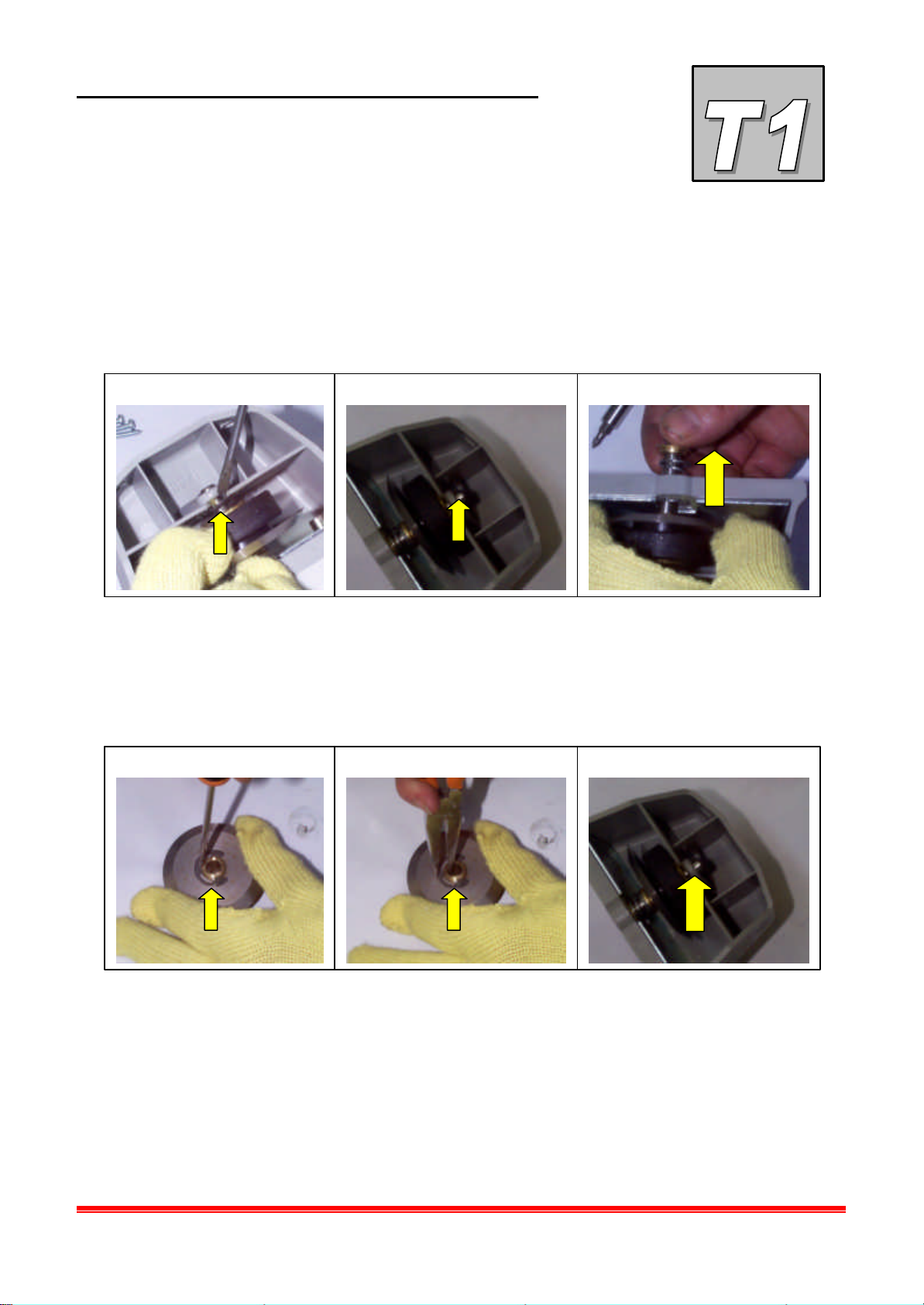
• Remove the elastic ring, using a normal screwdriver and keeping the blade pressed
towards the carriage 7.
• Remove the fulcrum screw of the blade holder shaft 8.
• Slide the shaft out of the carriage 9.
7 8 9
• Remove the elastic ruing and replace the rotating blade 10.
• Reassemble the elastic ring previously removed, locking it in its seat using pliers 11.
• Slide the shaft into its seat on the carriage, re-positioning all the elements removed and in
the same order. Put the fulcrum screw removed previously 12.
10 11 12
NEOLT
Power trim plus
SCH-TEC-2
Page 39
TECHNICAL SHEET
REPLACEMENT OF ROTATING
BLADE
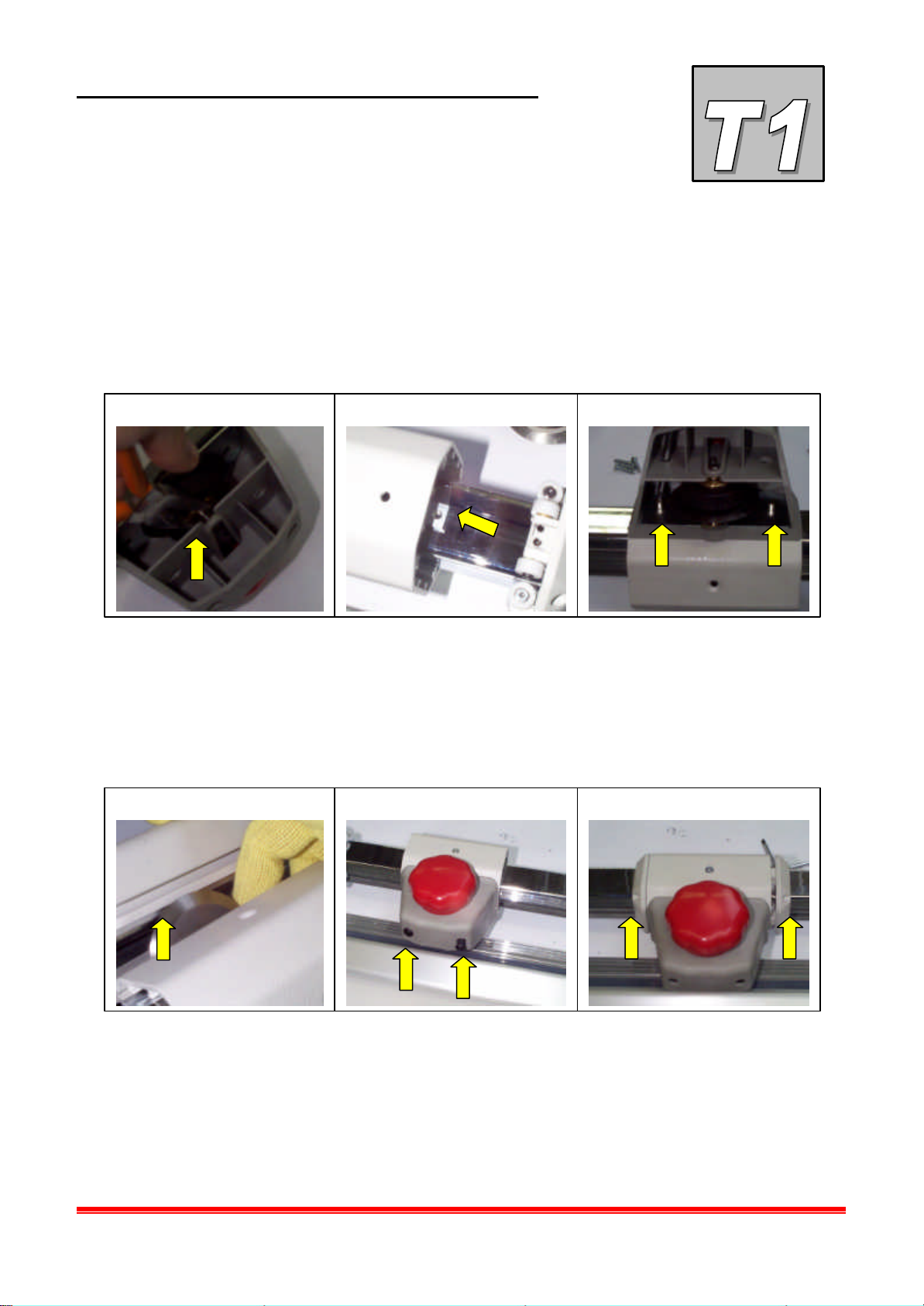
• Reposition the elastic ring, using pliers by keeping the blade pressed against the carriage
13.
• Position the plate joining the two parts of the carriage on the sliding bar and line up the
holes with the ones on the sliding profile 14.
• Position the two parts usi ng the screws previously removed 15.
13 14 15
• Turn the carriage over and push the blade over the fixed blade and the sheet holder, also
make sure the rubber is positioned above the Plexiglas sheet holder 16.
NEOLT
• Re-insert the two black plugs in the holes on the carriage 17.
• Re-insert the two plugs of the carriage and screw them to the carriage using the screws
previously removed 18.
16 17 18
Power trim plus
SCH-TEC-3
Page 40
TECHNICAL SHEET
REPLACEMENT OF ROTATING
BLADE
NEOLT
Power trim plus
SCH-TEC-4
Page 41

Page 42

NEOLT S.p.A
Via G. Galilei 8
24036 Ponte San Pietro (BG) – ITALY
035/468811
035/468886
NEOLT
2003
 Loading...