

Інструкція
експлуатації
з
та
встановлення
NS/NU-09EHBI
NS/NU-12EHBI
NS/NU-18EHBI
NS/NU-24EHBI
ВАЖЛИВА ПРИМІТКА: Ознайомтесь уважно з цим Посібником до моменту встановлення
або експлуатації кондиціонера. Обов’язково зберігайте його для довідок у майбутньому.

Інструкція з експлуатації
Підготовка до
Заходи з техніки безпеки
Технічні характеристики і функції приладу
Зміст
Посібник з експлуатації (без дистанційного управління)
Догляд і
обслуговування
Усунення недоліків у роботі
Утилізація
встановлення
3
5
7
12
13
15
7
1
2

1. ПІДГОТОВКА ДО ВСТАНОВЛЕННЯ
УВАГА!
УВАГА!
Цей символ вк
підключіть з'єднувальний кабель.
Його неправильне підключення може спричинити пошкодження електричних компонентів агрегату.
Обов’язково виконайте заземлення.
Не заземляйте агрегати на газові або водопровідні труби, блискавковідводи або телефонні дроти. Неправильно виконане
заземлення може викликати серйозну небезпеку ураження електричним струмом, що є потенційною причиною отримання
травми або смерті.
Утилізуйте пакувальні матеріали у безпечний спосіб.
Під час роботи з пакувальними матеріалами, такими як цвяхи, а також інші металеві або дерев’яні вироби існує ризик отримання
колотих ран або інших травм. Розірвіть і викиньте пластикові пакувальні пакети, щоб діти не гралися з ними. Діти, які граються
з такими матеріалами, піддаються небезпеці, пов’язаній із задухою.
Використання інших елементів може спричинити вихід агрегату з ладу, появу витоків води, ураження електричним струмом,
виникнення пожежі або пошкодження обладнання.
холодоагенту (R32), до контуру охолодження.
будь-який із захисних блокувальних вимикачів.
національних та місцевих правил монтажу електричної проводки.
ує на ймовірність отримання травм або загибелі людей.
аз
гат від джерела живлення. Належним чином Перш ніж виконувати будь-які електричні роботи, відключить агре
кабелі. Надійно зафіксуйте дроти у сполучних секціях Під час монтажу електричних з’єднань використовуйте зазначені
зовнішня сила.клемної коробки таким чином, щоб на клему не впливала будь-яка
ю горючих газів або парів газів.Не встановлюйте агрегат поблизу ділянок із високою концентраціє
поставки, або схвалені виробником компоненти.Використовуйте тільки монтажні деталі, які входять до комплекту
я повітря або інших речовин, крім зазначеного Під час встановлення чи переміщення системи уникайте потраплянн
ючи будь-які запобіжні пристрої або обходячи Заборонено вносити зміни до конструкції даного агрегату, видаля
до наданої інструкції з монтажу, а також вимог Електромонтажні роботи слід виконувати у суворій відповідності
ОБЕРЕЖНО!
ОБЕРЕЖНО!
ує на ймовірність заподіяння матеріальних збитків або випадків
Цей символ вк
аз
із серйозними наслідками.
Неправильний монтаж дренажного трубопроводу може призвести до появи витоків води та пошкодження майна.
Не встановлюйте кондиціонер у таких місцях:
-
Зона, в атмосфері якої присутнє мінеральне мастило або миш’яков
-
(наприклад, розчинник), або існує небезпека появи летючих горюч
-
Зона з наявністю обладнання, яке генерує електромагнітні поля а
Під час зберігання агрегату слід всіляко уникати ризику його ме
від уповноваженого галузевого органу, який підтверджує її компе
з холодоагентами згідно з визнаною в даній галузі системою оцін
ізноманітних деталей будьте особливо обережні.Щоб уникнути отримання травм під час роботи з гострими краями р
и умовами навколишнього середовища.Не розміщуйте внутрішні або зовнішні блоки в місцях з особливим
нь шуму, що виникає під час роботи агрегату, або Не встановлюйте обладнання у зонах, де може бути посилений ріве
сусідів.де робочий шум і звук повітря, що відводиться, можуть турбувати
ти тільки відповідно до інструкції з монтажу.Роботи з прокладання дренажних ліній/трубопроводу слід виконува
а кислота.
клад, газ сірчистої кислоти) або горючий газ Зона, де можуть накопичуватися або збиратися корозійний (напри
их речовин.
бо високочастотні гармонійні коливання.
ханічного пошкодження.
агенту, повинна мати відповідний дійсний сертифікат Будь-яка особа, яка виконує роботи, пов’язані з контуром холодо
тентність щодо безпечного поводження
ювання.
3

1. ПІДГОТОВКА ДО ВСТАНОВЛЕННЯ
УВАГА!
УВАГА!
ли не підключайте агрегат в одну розетку разом з Використовуйте тільки спеціально виділений силовий ланцюг. Ніко
іншими пристроями.
Щоб уникнути випадкового скидання стану термічного вимикача, жи
зовнішнього комутаційного пристрою, такого як таймер. Крім того
регулярно вмикається і вимикається під час експлуатації енергос
влення на це обладнання не повинно подаватися від
, агрегат не можна підключати до ланцюга, який
истеми.
абелі з ізоляцією у вигляді спеціальної трубки, яка Під час монтажу електричних з’єднань використовуйте зазначені к
забезпечує відповідну термічну стійкість провідника.
Застосування кабелів із непідходящими параметрами може спричинити появу витоку струму, виділення аномальної кількості
теплової енергії або виникнення пожежі.
зморожування або очищення, крім тих, які були Не використовуйте засоби, призначені для прискорення процесу ро
рекомендовані виробником.
жерел потенційного загоряння (наприклад, пристроїв із Агрегат слід зберігати у приміщенні, де немає постійно діючих д
о обігрівача). відкритим полум’ям, газового приладу або працюючого електричног
Цей виріб заборонено проколювати або спалювати.
у.Майте на увазі, що холодоагенти можуть не мати відчутного запах
р якого відповідає площі, яку він повинен охоплювати Агрегат слід зберігати у добре провітрюваному приміщенні, розмі
під час роботи.
Для моделей із холодоагентом R32:
Агрегат слід встановлювати, експлуатувати та зберігати у приміщ
≤9000 БТО/год: 13 м
>9000 БТО/год и ≤12000 БТО/год: 17 м
>12000 БТО/год и ≤18000 БТО/год: 26 м
>18000 БТО/год и ≤24000 БТО/год: 35 м
2
2
2
2
енні з площею понад 4 м
площа цього простору не перевищує 4 мАгрегат не можна розміщувати у приміщенні без вентиляції, якщо
риміщення становить:Для моделей із холодоагентом R32 мінімально необхідний розмір п
2
.
2
.
4
ЗАСТЕРЕЖЕННЯ
Ця позначка вказує, що недотримання інструкції може призвести до смерті
або серйозних травм.
ПОПЕРЕДЖЕННЯ
Ця позначка вказує, що недотримання інструкції може викликати легке
ушкодження здоров’я або пошкодження приладу або іншого майна.
Заходи з техніки безпеки
Ознайомтесь із заходами з техніки безпеки
Неправильне встановлення внаслідок недотримання інструкцій може викликати серйозні
пошкодження або травми. Рівень тяжкості потенційного збитку або травм класифікуються як
ЗАСТЕРЕЖЕННЯ або ПОПЕРЕДЖЕННЯ.
Цей прилад може використовуватись дітьми у віці від 8 років і особами з обмеженими
фізичними, сенсорними або розумовими здібностями, або відсутністю досвіду і знань, якщо
вони перебувають під наглядом або їм були надані вказівки щодо використання приладу
безпечним способом і вони розуміють присутність небезпеки. Діти не повинні гратись з
приладом. Забороняється очищення і технічне обслуговування дітьми без нагляду.
ЗАСТЕРЕЖЕННЯ ПІД ЧАС ВСТАНОВЛЕННЯ
Зверніться до уповноваженого представника з проханням встановити цей кондиціонер.
Встановлення його неналежним чином може викликати витік води, ураження електричним
струмом або пожежу.
Всі ремонтні роботи та технічне обслуговування цього приладу повинні проводитись
спеціалістом авторизованого сервісного центру. Ремонт, проведений неналежним
чином, може викликати серйозні травми або пошкодження виробу.
ЗАСТЕРЕЖЕННЯ ЩОДО ВИКОРИСТАННЯ ВИРОБУ
У разі виникнення аномальної ситуації (як, наприклад, запаху горілого) негайно вимкніть
прилад і витягніть вилку із розетки. Зверніться до представника авторизованого
сервісного центру для отримання вказівок, щоб уникнути ураження електричним струмом,
пожежі або травми.
Не вставляйте пальці, палиці та інші предмети в отвори для забору та випуску повітря. Це
може призвести до травми, оскільки вентилятор може обертатися на високих швидкостях.
Не використовуйте займисті аерозолі, такі як: лак для волосся, лак або фарба поблизу
приладу. Це може викликати пожежу або горіння.
Не використовуйте кондиціонер в місцях поблизу або навколо горючих газів. Виділення
газу можуть збиратись навколо приладу і викликати вибух.
Не вмикайте кондиціонер у вологому приміщенні (наприклад, ванній кімнаті або пральні).
Це може викликати ураження електричним струмом і погіршення стану виробу.
Не піддавайте свій організм впливу холодного повітря протягом тривалого періоду часу.
ЗАСТЕРЕЖЕННЯ
ЗАСТЕРЕЖЕННЯ ЩОДО ЕЛЕКТРИЧНИХ ЧАСТИН
Використовуйте тільки призначений шнур живлення. Якщо цей шнур пошкоджений, він
повинен бути замінений виробником або авторизованим сервісним центром.
5
Не забруднюйте вилку. Видаляйте пил або бруд, які накопичуються на або навколо вилки.
Брудна вилка може викликати пожежу або ураження електричним струмом.
Не тягніть за шнур живлення, щоб від’єднати прилад. Візьміться міцно за вилку і витягніть
її з розетки. Якщо тягнути безпосередньо за шнур, це може пошкодити його, що може
викликати пожежу або ураження електричним струмом.
Не використовуйте подовжувач, не продовжуйте шнур живлення вручну або не
під’єднуйте інші пристрої до розетки, до якої під’єднаний кондиціонер. Незадовільні
електричні з'єднання, ізоляція і недостатня напруга можуть викликати пожежу.
ЗАСТЕРЕЖЕННЯ ЩОДО ЧИЩЕННЯ І ОБСЛУГОВУВАННЯ
Вимкніть прилад і витягніть вилку перед очищенням. Невиконання цієї вимоги може
призвести до ураження електричним струмом.
Для чищення кондиціонера не використовуйте надмірний обсяг води.
Для чищення кондиціонера не використовуйте горючі миючі засоби. Горючі миючі засоби
можуть призвести до пожежі або деформації.
ПОПЕРЕДЖЕННЯ
Якщо кондиціонер використовується разом з пальниками або іншими нагрівальними
приладами, ретельно провітріть приміщення, щоб уникнути дефіциту кисню.
Вимкніть і від’єднайте живлення кондиціонера, якщо ви не збираєтеся використовувати
його протягом тривалого часу.
Вимкніть і від’єднайте прилад під час грози.
Переконайтеся, що конденсат може безперешкодно витікати з приладу.
Не вмикайте кондиціонер мокрими руками. Це може призвести до ураження електричним
струмом.
Не використовуйте прилад для будь-яких інших цілей, аніж за його призначенням.
Не ставайте або не кладіть предмети на верхню частину зовнішнього блоку.
Не допускайте експлуатацію кондиціонеру протягом тривалого періоду часу з закритими
дверима або вікнами або в умовах високого рівня вологості.
6
Технічні характеристики і функції приладу
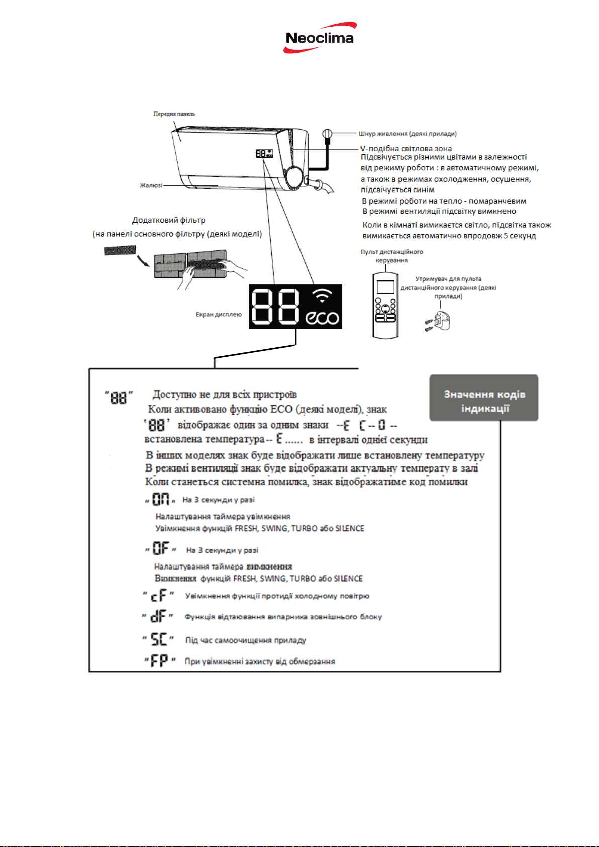
Частини приладу
7

Режим COOL
Режим HEAT
Режим DRY
ДЛЯ ПРИЛАДІВ З
ДОДАТКОВИМ
ЕЛЕКТРИЧНИМ
НАГРІВАЧЕМ
Якщо зовнішня
температура нижче 0°C
(32°F ), настійливо
рекомендуємо не
вимикати прилад увесь
час, щоб забезпечити
його безперебійну
роботу.
Температура
повітря у
приміщенні
17°C - 32°C
- 90°F)
0°C - 30°C
(32°F - 86°F)
10°C - 32°C
(50°F - 90°F)
Температура
повітря
зовні
приміщення
0°C - 43°C
(32°F - 122°F)
0°C - 50°C
(32°F - 126°F)
-15°C - 50°C
(5°F - 122°F)
(Для пристроїв з
встановленим
додатковим
низькотемпературним
обладнанням.)
Режим HEAT
Режим DRY
Температура повітря
у приміщенні
0°С-30°C (32°86°F)
10°-32°C (50°-90°F)
Температура повітря
зовні приміщення
-7°-24°C (19°-75°F)
11°-43°C (52°-109°F)
-7°-43°C (19°-109° F)
(Для пристроїв з
встановленим
додатковим
низькотемпературним
обладнанням.)
18°-
-109°F)
18°-52°C (64°-126 °F)
(Для спеціальних
моделей для тропічного
клімату)
18°-52°C (64°-126° F)
(Для спеціальних
моделей для
тропічного клімату)
Досягнення оптимальної продуктивності роботи
Оптимальна продуктивність для режимів COOL (ОХОЛОДЖЕННЯ), HEAT (ОБІГРІВ) і DRY
(ОСУШЕННЯ) може бути досягнута у наступних температурних діапазонах. Якщо
кондиціонер використовується за межами цих діапазонів, активуються деякі функції захисту
безпеки і тому прилад працює з меншою продуктивністю.
Моделі пристроїв з компресором інверторного типу
(62°F
-15°C - 30°C
(5°F - 75°F)
Моделі виробів з фіксованою частотою роботи компресора
Для подальшої оптимізації продуктивності роботи приладу, виконайте такі дії:
• Тримайте двері та вікна закритими.
• Обмежуйте споживання енергії за допомогою функції таймера увімкнення і таймера
вимкнення.
• Не блокуйте притік або витік повітря.
• Регулярно перевіряйте і очищайте повітряний фільтр.
Режим COOL
17°-32°C (62°-90°F)
18°-43°C (64°-109°F)
52°C (64°
8

Для детального пояснення кожної функції,
зверніться до Посібника з дистанційного
керування.
• Wi-Fi Контроль (деякі прилади)
Wi-Fi Контроль дозволяє Вам керувати
кондиціонером за допомогою мобільного
телефону і Wi-Fi з'єднання.
Інші функції
• Автоматичний перезапуск
Якщо під час роботи приладу зникає напруга
живлення, він буде автоматично повторно
запущений з попередніми налаштуваннями
після відновлення живлення.
• Збереження куту нахилу жалюзі у пам’яті
(деякі одиниці)
При увімкненні приладу жалюзі автоматично
відновить свій останній кут нахилу.
• Анти-цвіль (деякі прилади)
При вимкненні режимів COOL, AUTO
(COOL) або DRY, кондиціонер буде
продовжувати працювати на дуже малій
потужності, щоб висушити конденсовану
воду і запобігти росту цвілі.
• Виявлення витоку охолоджуючого агенту
(деякі прилади)
У разі виявлення витоку охолоджуючого
агенту на внутрішньому блоці буде
автоматично відображено «EC»
• Робота у безшумному режимі (деякі
прилади)
Натисканням кнопки LED на пульті
дистанційного керування можна вимкнути
індикацію на дисплеї, а також вимкнути
зумер кондиціонера.
Для докладного пояснення розширених
функцій приладу (наприклад, режиму
TURBO і функції самоочищення), зверніться
до Посібника з дистанційного керування.
ПРИМІТКА ДЛЯ ІЛЮСТРАЦІЙ
Ілюстрації у цьому посібнику подані з метою пояснення. Фактична форма вашого
внутрішнього приладу може дещо відрізнятись. Фактична форма має переважне значення.
9

• Налаштування напрямку повітряного
потоку
Налаштування вертикального напрямку
повітряного потоку
Під час роботи приладу, використовуйте
кнопку SWING/DIRECT, щоб задати
напрямок (вертикальне положення)
повітряного потоку.
1. Натисніть один раз кнопку
SWING/DIRECT, щоб активувати жалюзі.
Кожен раз, коли ви натискаєте кнопку,
жалюзі будуть регулюватись на 6°.
Натискайте кнопку до моменту встановлення
напрямку, якому ви віддаєте перевагу.
2. Для того, щоб жалюзі переміщувались
вгору і вниз безперервно, утримуйте кнопку
SWING/DIRECT протягом 3 секунд.
Натисніть її ще раз, щоб зупинити
автоматичну функцію.
Налаштування горизонтального напрямку
повітряного потоку
Не просовуйте пальці всередину і не
торкайтесь пальцями поблизу отво
рів
для всмоктування або викидання
повітря на приладі.
Високошвидкісний вентилятор
всередині блоку може травмувати
вас.
Горизонтальний напрямок повітряного
потоку повинен встановлюватись вручну.
Візьміться за важіль відбивача (див. Рис.2.3)
і вручну налаштуйте у потрібному напрямку.
На деяких приладах горизонтальний кут
повітряного потоку може бути встановлений
за допомогою пульта дистанційного
керування. Зверніться до Посібника з
дистанційного керування.
Рис. 2.3
Примітка для жалюзі
При використанні режиму COOL або DRY, не
встановлюйте жалюзі занадто вертикально
на тривалий період часу. Це може викликати
конденсацію вологи на лезі жалюзі, краплі
якої будуть падати на підлогу або меблі (див.
Рис. 2.2).
При використанні режимів COOL або HEAT
встановлення жалюзі занадто вертикально
може знизити продуктивність приладу
внаслідок обмеження циркуляції потоку
повітря.
Не рухайте жалюзі вручну. Це призведе до
втрати синхронізації роботи жалюзі. Якщо
таке відбувається, вимкніть прилад і
від'єднайте його на декілька секунд від
мережі, а потім знову запустіть прилад.
Не встановлюйте жалюзі занадто
вертикально на тривалий період
часу. Це може викликати
конденсацію вологи, краплі якої
будуть падати на меблі
Рис. 2.2.
Важіль
відбивача
10
Параметри налаштування жалюзі
скасуються.
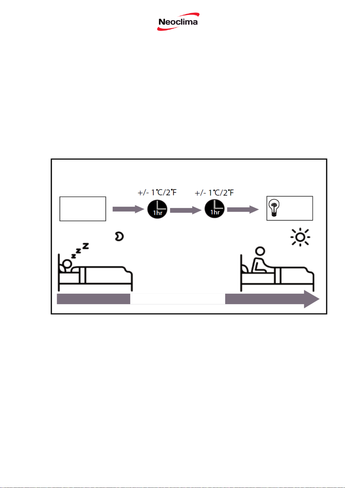
Неактивний режим роботи
Функція SLEEP використовується для
зменшення споживання енергії під час
вашого сну. Ця функція може бути
активована тільки за допомогою пульту
дистанційного керування.
Натисніть на кнопку SLEEP, коли ви готові
йти спати. У режимі COOL прилад збільшує
налаштовану температуру повітря у кімнаті
на 1°C (2°F) через 1 годину, а також
додатково на 1°C (2°F) ще через одну годину.
В режимі HEAT прилад знижує налаштовану
температуру повітря у кімнаті на 1°C (2°F)
через 1 годину, а також буде зменшуватись
додатково на 1°C (2°F) ще через годину.
Нова температура буде підтримуватись
протягом 7 годин, потім прилад вимкнеться
автоматично.
Примітка: Функція SLEEP не працює у
режимі FAN або DRY.
Збереження енергії протягом сну
Неактивний режим роботи
Встановлена
температура
1 год.
Таймер
вимкнення
через 7 год.
1 год.
11

Експлуатація приладу без пульта
дистанційного керування
ПОПЕРЕДЖЕННЯ
У випадку, коли пульт дистанційного
керування не працює, пристрій може
працювати в ручному режимі за
допомогою кнопки ручного управління
(MANUAL CONTROL), яка знаходиться
на внутрішньому блоці. Зверніть увагу,
ручна експлуатація не є довгостроковим
вирішенням проблеми, і рекомендується
експлуатація за допомогою пульта
дистанційного керування.
Кнопка ручного управління призначена тільки
для тестування і роботи в аварійному режимі.
Будь ласка, не використовуйте цю функцію, якщо
пульт дистанційного управління працює
нормально. Для відновлення нормальної роботи і
увімкнення приладу використовуйте пульт
дистанційного управління.
ДО ПОЧАТКУ ЕКСПЛУАТАЦІЇ В
РУЧНОМУ РЕЖИМІ
Прилад повинен бути вимкнений до
початку роботи у ручному режимі
1. Знайдіть кнопку ручного управління на
правій бічній панелі пристрою.
2. Натисніть кнопку MANUAL CONTROL
один раз для активації режиму FORCED
AUTO.
3 . Натисніть кнопку MANUAL
CONTROL знову для активації режиму
FORCED COOLING
4. . Натисніть кнопку MANUAL
CONTROL в третій раз, щоб вимкнути
прилад.
Посібник з експлуатації (без дистанційного керування)
ПЕРІОДИЧНЕ СЕРВІСНЕ ОБСЛУГОВУВАННЯ
проводите періодичне сервісне обслуговування спеціалістами авторизованих сервісних
центрів не менше двох разів на рік.
1. Чистка внутрішнього блоку;
2. Чистка зовнішнього блоку;
3. Перевірка системи дренажу;
4. Перевірка робочих параметрів;
5. Дозаправка холодоагентом в разі необхідності.
Сервісне обслуговування не входить до переліку гарантійних робіт і сплачується за чинними
тарифами Авторизованого сервісного центру.
Для надійної та тривалої роботи кондиціонерів повітря виробник рекомендує
При сервісному обслуговуванні кондиціонера виконуються наступні роботи:
Кнопка ручного
управління
12
Очищення внутрішнього блоку
ДО ПОЧАТКУ ОЧИЩЕННЯ І
ОБСЛУГОВУВАННЯ
ЗАВЖДИ ВИМИКАЙТЕ СИСТЕМУ
КОНДИЦІОНУВАННЯ І ВІД’ЄДНУЙТЕ
ЇЇ ВІД МЕРЕЖІ ЖИВЛЕННЯ
ПОПЕРЕДЖЕННЯ
Для витирання приладу використовуйте
м'яку, суху тканину. Якщо прилад надто
забруднений, для очищення можна
використовувати тканину, змочену в
теплій воді.
• Не використовуйте хімічні речовини або
хімічно оброблені тканини для чищення
приладу
• Не використовуйте бензин, розчинник
для фарби, порошок для полірування або
інші розчинники для очищення приладу.
Вони можуть викликати розтріскування і
деформацію пластикової поверхні.
• Не використовуйте воду з температурою
вище 40°C (104°F) для очищення
передньої панелі. Це може викликати
деформування або знебарвлення панелі.
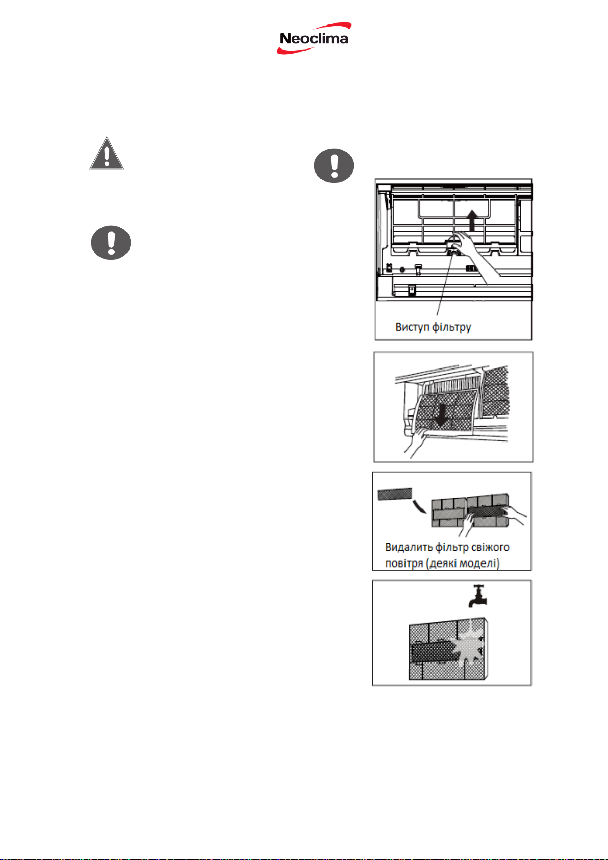
ОЧИСТКА ПОВІТРЯНОГО ФІЛЬТРА
Забитий брудом кондиціонер може
зменшити ефективність охолодження, а
також це може бути шкідливо для вашого
здоров'я. Очищення фільтру потрібно
проводити один раз на два тижні.
1. Підніміть передню панель внутрішнього
блоку. Повітряний фільтр знаходиться під
верхньою решіткою повітрозбірника.
2. Візьміться за виступ на кінці фільтра,
підніміть його угору, а потім потягніть на
себе.
3. Тепер витягніть фільтр.
4. Очистіть великий повітряний фільтр
теплою мильною водою. Потрібно
використовувати м'який миючий засіб.
5. Промийте фільтр прісною водою,
струсіть надлишок води.
6. Висушіть його в прохолодному, сухому
місці і подалі від впливу прямих сонячних
променів.
7. Встановіть фільтр на місце, закрийте
передню панель внутрішнього блоку.
Догляд і обслуговування
ПОПЕРЕДЖЕННЯ
Рис. 5.1
Не торкайтесь фільтра освіжаючого
повітря (Plasma) протягом
принаймні 10 хвилин після
вимкнення приладу
13

Обслуговування перед періодом
тривалого невикористання
Якщо плануєте не використовувати
кондиціонер тривалий час, виконайте такі
заходи:
Обслуговування –
Обстеження до початку сезонної роботи
Після тривалих періодів невикористання або
перед періодами частого використання,
виконайте такі заходи:
ПОПЕРЕДЖЕННЯ
• Перед зміною фільтра або очищенням вимкніть
прилад і від'єднайте його від живлення.
• Під час видалення фільтра не торкайтеся
металевих деталей у блоці. Гострі металеві краї
можуть спричинити порізи.
• Не використовуйте воду для очищення
внутрішньої поверхні внутрішнього блоку. Це
може пошкодити ізоляцію і викликати ураження
електричним струмом.
• Уникайте попадання на фільтр прямих
сонячних променів під час сушіння. Це може
зменшити розмір фільтру.
Сигналізатор повітряного фільтра (на вибір)
Сигналізатор очищення повітряного фільтру
Після 240 годин роботи на екрані дисплея на
внутрішньому блоці блимає "CL". Це
нагадування про очищення фільтра. Через 15
секунд, екран повернеться до попереднього
стану.
Щоб скасувати нагадування, 4 рази натисніть
кнопку LED на пульті дистанційного управління,
або 3 рази натисніть кнопку ручного управління.
Якщо ви не скасували нагадування, індикатор
"CL" буде блимати знову, коли ви перезапускаєте
прилад.
Очистити усі фільтри
Увімкнути функцію FAN
для повного осушення
Сигналізатор заміни повітряного фільтра
Після 2 880 годин роботи на екрані дисплея на
внутрішньому блоці блимає «nF». Це нагадування
про заміну фільтра. Через 15 секунд, екран
повернеться до попереднього стану.
Щоб скасувати нагадування, 4 рази натисніть
кнопку LED на пульті дистанційного управління,
або 3 рази натисніть кнопку ручного управління.
Якщо ви не скасували нагадування, індикатор
«nF»
буде блимати знову, коли ви перезапускаєте
прилад.
ПОПЕРЕДЖЕННЯ
• Будь-яке обслуговування та очищення
зовнішнього блоку повинні проводитись
спеціалістами авторизованого сервісного
центру.
• Будь-який ремонт приладу повинен
проводитись спеціалістами авторизованого
сервісного центру.
Перевірити цілісність кабелів
Очистити усі фільтри
Перевірити на предмет
протікання
Замінити батарейки
Пересвідчитись, що притік і витік повітря
не заблоковані
14
У регіонах з вологим кліматом, велика різниця температур між
повітрям в кімнаті і кондиційним повітрям може викликати появу
розпилення білого кольору.
Коли пристрій запускається в режимі HEAT після
розморожування, розпилення білого кольору може виділятися
внаслідок вологи, що утворюється на теплообміннику в процесі
розморожування.
Можлива причина
Коли жалюзі змінюють налаштування може виникати шипіння .
Після запуску приладу в режимі HEAT може виникати
скрипучий звук внаслідок розширення і стиснення деталей із
пластмас.
Низький шиплячий звук під час роботи: Це нормально і
викликано холодоагентом, що протікає через внутрішній і
зовнішній блоки.
Низький шиплячий звук під час запуску системи, відразу після
зупинення або розморожування: Шум не є відхиленням від
нормальної роботи і викликаний зупинкою руху холодоагенту
або зміною напрямку руху.
Скрип: нормальне розширення і стискання пластикових і
металевих деталей, викликаних змінами температури під час
роботи може призвести до скрипучого шуму.
У приладі виникають різні звуки в залежності від його поточного
режиму роботи.
Прилад може накопичувати пил під час тривалих періодів
Усунення недоліків у роботі
Якщо настає будь-який з нижчезазначених випадків, негайно вимкніть прилад!
• Шнур живлення пошкоджений або аномально нагрівається
• Ви відчуваєте запах горілого
• Прилад видає гучні або аномальні звуки
• Силовий запобіжник плавиться або автоматичний вимикач часто спрацьовує
• Попадання води або інших предметів
НЕ НАМАГАЙТЕСЯ УСУНУТИ ЦІ ПРОБЛЕМИ САМОСТІЙНО! ВІДРАЗУ
ЗВЕРТАЙТЕСЬ ДО АВТОРИЗОВАНОГО СЕРВІСНОГО ЦЕНТРУ!
Загальні питання
Наступні проблеми не є відмовами у роботі приладу, і тому не потребують ремонту:
Проблема
Пристрій не вмикається
при натисканні на кнопку
ON/OFF
Прилад змінює режим
COOL/HEAT на режим
FAN
Внутрішній блок виділяє
розпилення білого
кольору
Внутрішній і зовнішній
блок виділяють
розпилення білого
кольору
ЗАХОДИ БЕЗПЕКИ
Можлива причина
Прилад має 3-хвилинну функцію затримки, яка запобігає
перевантаженню приладу. Пристрій не може бути знову
запущений протягом трьох хвилин після вимкнення.
Пристрій може змінювати свої налаштування, щоб уникнути
утворення інею. Як тільки температура підвищиться, прилад
знову почне працювати у попередньому режимі.
Досягнута задана температура, і в цей момент вимикається
компресор. Прилад буде продовжувати працювати, якщо
температура повітря знову зміниться .
Проблема
Шум внутрішнього блоку
Шум у внутрішньому і
зовнішньому блоках
Шум зовнішнього блоку
Пил виділяється з
15
внутрішнього або
зовнішнього блоку
невикористання, який виділяється під час вмикання пристрою.
Цей ефект може бути пом'якшений, накриваючи прилад
протягом тривалих періодів невикористання.
Прилад виділяє
неприємний запах
Блок може поглинати запахи з навколишнього середовища
(наприклад, меблів, кухні, тютюнового диму і т .д.), які будуть
виділятися під час його експлуатації.
Фільтри покриті цвіллю і потребують очищення.
Вентилятор зовнішнього
блоку не працює
Під час роботи швидкість вентилятора регулюється для
оптимізації роботи приладу.
Нерівномірна і
непередбачувана робота
або блок не реагує на
управління
Перешкоди від антен стільникового зв'язку і віддалених
прискорювачів можуть викликати збій у роботі приладу.
У цьому випадку, спробуйте наступне:
• Вимкніть живлення, потім знову увімкніть.
• Натисніть кнопку ON/OFF на пульті дистанційного керування,
щоб відновити роботу.
Проблема
Можлива причина
Вирішення
Низька
ефективність
охолодження
Налаштування температури може бути
вище кімнатної температури
середовища
Зниження налаштувань
температури
Забруднення теплообмінника на
внутрішньому або зовнішнього блоках
Очищення теплообмінника
Повітряний фільтр забруднений
Зніміть фільтр і очистіть його
відповідно до вказівок
Блокування притоку або витоку повітря
Вимкніть пристрій, видаліть
перешкоду і знову увімкніть
його
Двері і вікна відкриті
Переконайтесь, що усі двері і
вікна закриті під час роботи
приладу
Надмірне тепло утворюється сонячними
променями
Зачиніть вікна і штори в
періоди високої зовнішньої
температури або яскравого
сонця
Занадто багато джерел тепла в
приміщенні (люди, комп'ютери,
електроніка, і т. д.)
Зменшити кількість джерел
тепла
Активована функція SILENCE
Функція SILENCE може
знижувати ефективність
роботи шляхом зменшення
робочої частоти. Вимкніть
функцію SILENCE.
Примітка: Якщо проблема залишається, зверніться до місцевого представника або в
найближчий авторизований сервісний центр. Надайте їм докладний опис несправності
приладу, а також номер його моделі.
У разі виникнення несправності перевірте наступні пункти перед зверненням за ремонтом
16
Проблема
Можлива причина
Вирішення
Прилад не працює
Відсутність живлення
Почекайте до відновлення
енергопостачання
Живлення вимкнене
Увімкніть живлення
Згорів запобіжник
Замініть запобіжник
Розрядились батарейки пульта
дистанційного управління
Замініть батарейки
Активована функція 3-хвилинного
захисту приладу
Почекайте 3 хвилини до
перезапуску приладу
Активований таймер
Вимкніть таймер
Прилад часто
вмикається і
зупиняється
Занадто багато або мало
холодоагенту в системі
Зверніться до монтажної
організації для перевірки на
наявність витоків холодоагенту в
місцях підключення.
Занадто висока або мала напруга
Підключить прилад до іншої
мережі.
Низька
ефективність
нагрівання
Зовнішня температура нижча від 7°C
(44,5°F)
Використайте додатковий
нагрівальний пристрій
Холодне повітря надходить через
вікна і двері
Переконайтесь, що усі вікна і
двері зачинені
Низький рівень холодоагенту
внаслідок витікання або тривалого
використання
Переконайтеся у відсутності
витоків, зверніться до монтажної
організації для перевірки на
наявність витоків холодоагенту в
місцях підключення.
Лампи індикатора
продовжують
блимати
Прилад може припинити роботу або продовжувати працювати безпечно.
Якщо лампи індикатора продовжують блимати або з'являється помилка
коду індикації, почекайте близько 10 хвилин. Проблема може
вирішитись сама по собі.
Якщо ні, вимкніть живлення, а потім знову увімкніть. Увімкніть прилад.
Якщо проблема не усувається, вимкніть живлення і зверніться у
найближчий центр обслуговування клієнтів.
Помилка коду
індикації
з’являється на
екрані дисплею
внутрішнього
блоку:
• E0, E1, E2…
• P1, P2, P3…
• F1, F2, F3…
ПРИМІТКА: Якщо проблема не усувається після проведення вищезазначеної перевірки і
діагностики, негайно вимкніть прилад і зверніться у авторизований сервісний центр.
Утилізація
Цей прилад містить холодоагент та інші потенційно небезпечні матеріали. Під час його
утилізації законодавство вимагає спеціального видалення і обробки. Не викидайте цей виріб
разом з побутовими відходами. Утилізація даного пристрою у лісі або інших природних
околицях ставить під загрозу ваше здоров'я, і це задає шкоду для навколишнього середовища.
Небезпечні речовини можуть проникнути у ґрунтові води і у ланцюг харчування.
17
Інструкція з монтажу
NS/NU-09EHBI
NS/NU-12EHBI
NS/NU-18EHBI
NS/NU-24EHBI
ВАЖЛИВА ПРИМІТКА: Ознайомтесь уважно з цим Посібником до моменту встановлення або
експлуатації кондиціонера. Обов’язково зберігайте його для довідок у майбутньому

Інструкція з монтажу
Зміст
Допоміжні пристосування 20
Стисла інформація про встановлення приладу 21
Складові частини приладу 23
Встановлення внутрішнього блоку 24
1. Вибір місця встановлення 24
2. Кріплення монтажної пластини до стіни 25
3. Свердління отвору у стіні для сполучного трубопроводу 25
4. Підготовка трубопроводу холодоагенту 27
5. Під’єднання дренажного шлангу 28
6 Під’єднання сигнального кабелю 30
7 Обернення трубопроводів та кабелів 31
Встановлення зовнішнього блоку 32
1. Вибір місця установки 32
2. Встановлення дренажного коліна 33
3. Закріплення зовнішнього блоку 34
4. Під’єднання сигнального кабелю і кабелю живлення 35
З’єднання трубопроводу з холодоагентом 37
А Примітка щодо довжини трубопроводу 37
В Інструкції для під’єднання - трубопровід з холодоагентом 37
1. Обрізання труб 37
2. Видалення задирок 38
3 Розширення кінців труб 38
4. З’єднання труб 39
ВИДАЛЕННЯ ПОВІТРЯ 41
Інструкції для видалення 41
Примітка про додавання холодоагенту 42
Перевірка витоку струму і газу 43
ПРОБНА ЕКСПЛУАТАЦІЯ 44
ІНФОРМАЦІЯ
ПРО
ПІДТВЕРДЖЕННЯ
ПРОДУКТУ
46
19
керування
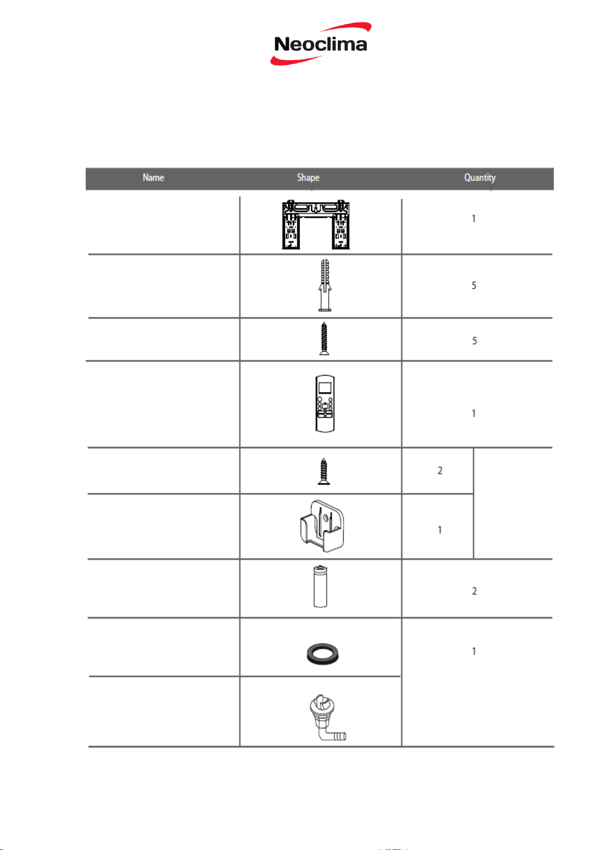
Допоміжні пристосування
Система кондиціювання повітря поставляється з наступними допоміжними пристосуваннями. Для
встановлення кондиціонера використовуйте усі монтажні деталі і пристосування. Неправильне
встановлення може призвести до протікання води, ураження електричним струмом і пожежі або
виходу приладу з ладу.
Монтажна пластина
Затискач
Кріпильний гвинт
монтажної пластини
Пульт дистанційного
Кріпильний гвинт утримувача
пульта дистанційного
Утримувач пульта
дистанційного
керування
Суха батарейка AAA.LR0
Ущільнювач
Опція
(тільки для охолоджуючих і
нагрівальних моделей
Дренажне з’єднання
20
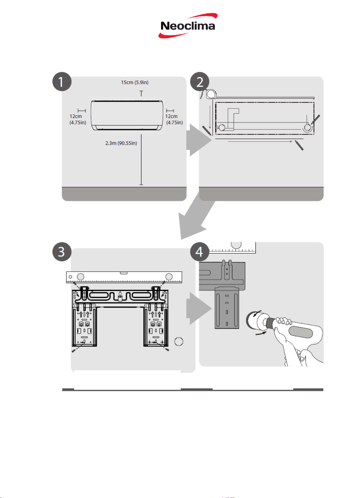
Стисла інформація про встановлення приладу
Вибір місця для встановлення
(стор. 11)
Прикріплення монтажної пластини
(стор. 12)
Визначення положення отвору у стіні
(стор. 12)
Свердління отвору у стіні
(стор. 12)
21
З’єднання трубопроводу
(стор. 25)
Під’єднання кабелю
(стор. 17)
Обернення трубопроводу і кабелів
(стор. 18)
Підготовка дренажного шлангу
(стор. 14)
Монтаж внутрішнього блоку
(стор. 18)
22

ПРИМІТКА ДЛЯ ІЛЮСТРАЦІЙ
Ілюстрації у цьому посібнику подані з метою пояснення. Фактична форма вашого внутрішнього
приладу може дещо відрізнятись. Фактична форма має переважне значення.
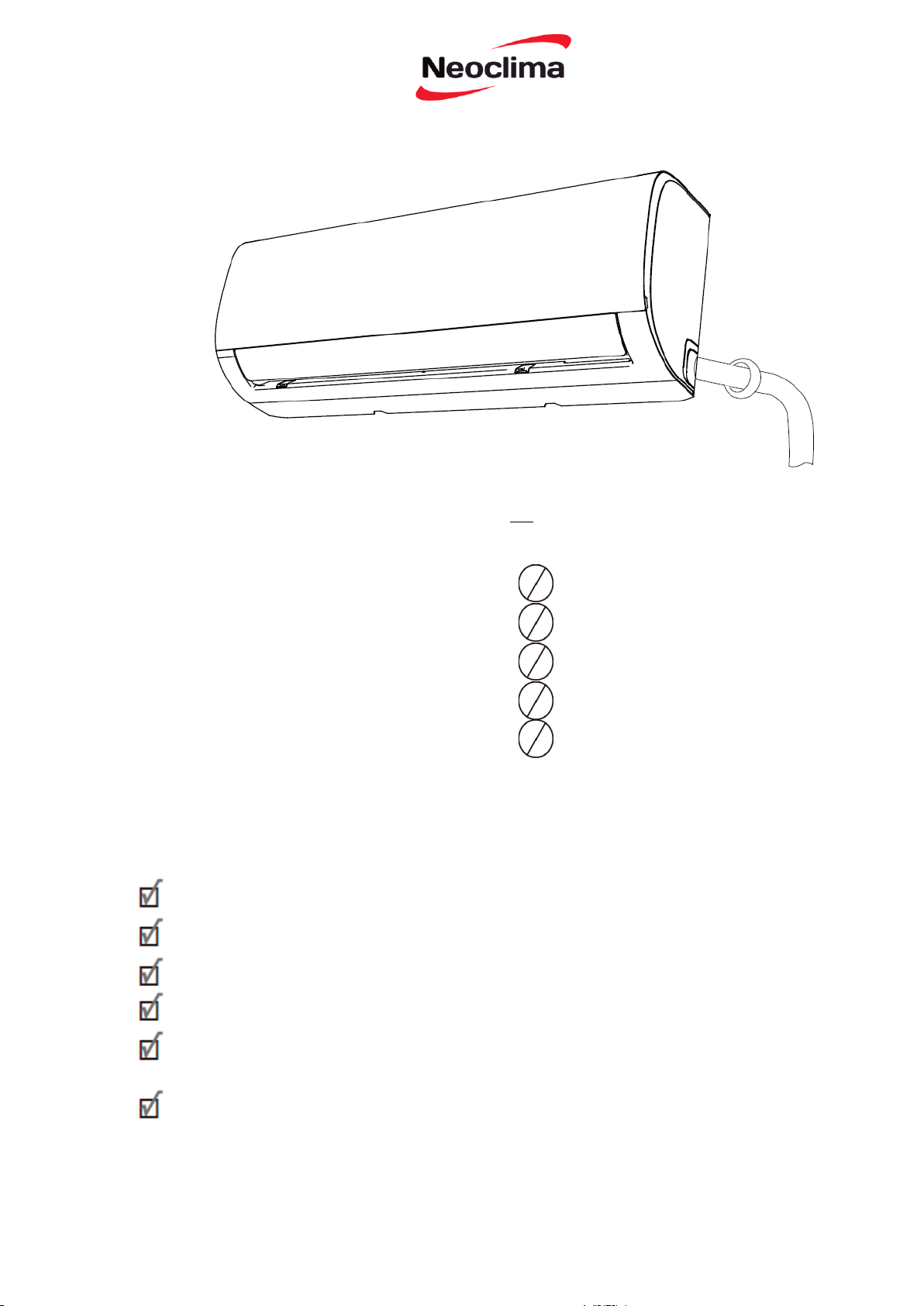
Складові частини приладу
Настінна монтажна пластина
Мережевий кабель (у деяких приладах)
Передня панель
Жалюзі
Дренажний шланг
Сигнальний кабель
Трубопровід холодоагенту
Рис 3.1
Пульт дистанційного керування
(у деяких приладах)
Держатель пульту
Мережевий кабель
зовнішнього блоку
(у деяких приладах)
23
Вказівки для встановлення – внутрішній блок
НЕ встановлюйте пристрій в наступних
місцях:
До моменту встановлення
Поруч з будь-яким джерелом тепла,
пару або горючого газу
Поблизу легкозаймистих предметів,
таких як штори або одяг
Поруч з будь-якою перешкодою, що
може блокувати циркуляцію повітря
Поряд з дверима
У місці, яке знаходиться під впливом
прямих сонячних променів
Перед встановленням внутрішнього блоку
ознайомтесь з маркуванням на коробці виробу,
щоб переконатися, що номер моделі
внутрішнього блоку збігається з номером моделі
зовнішнього блоку.
Крок 1: Оберіть місце встановлення
Перед встановленням внутрішнього блоку ви
повинні вибрати відповідне місце. Нижче
наведені стандарти, які допоможуть вам вибрати
підходяще місце для блоку.
Примітка для отвору у стіні
Правильне місце встановлення відповідає таким
стандартам:
У випадку, якщо немає фіксованого
трубопроводу з холодоагентом:
Вибираючи місце встановлення, враховуйте,
що потрібно залишити достатньо місця для
отвору у стіні (див. свердління отвору в стіні
для сполучення труб) для сигнального кабелю
і трубопроводу холодоагенту, що з'єднують
внутрішній і зовнішній блоки.
Положенням за замовчуванням для всіх
трубопроводів є права частина внутрішнього
блоку (в той час як перед блок). Однак, прилад
може вмістити трубопровід як для лівої і
правої сторін.
Добра циркуляція повітря
Зручний дренаж
Шум від блоку не заважає іншим людям
Міцне і тверде місце, щоб запобігти
вібрації
Достатньо міцне, щоб витримати вагу
блоку
Розташування принаймні один метр від
усіх інших електричних пристроїв
(наприклад, телевізора, радіо,
комп'ютера)
Встановлення внутрішнього блоку
24
Крок 2: Прикріпіть монтажну
пластину до стіни
Монтажна пластина є пристроєм, на
якому ви будете монтувати внутрішній
блок.
1. Викрутіть гвинт, який кріпить
монтажну пластину до задньої частини
внутрішнього блоку.
1. Визначте місце розташування отвору у стіні
відповідно до положення монтажної пластини.
Ознайомтесь з Розмірами монтажної пластини на
наступній сторінці, щоб визначити оптимальне
положення. Отвір у стіні повинен мати діаметр
щонайменше 65 мм (2,5 дюйма) і під дещо нижчим
кутом, щоб полегшити дренаж.
2. Прикладіть монтажну пластину до
стіни в місці, яке відповідає стандартам
у кроці «Вибір місця встановлення (див.
Розміри монтажної пластини для
докладної інформації про розміри
монтажної пластини).
2. Щоб просвердлити отвір у стіні, використовуйте
порожисте свердло 65мм (2,5 дюйма).
Переконайтеся, що отвір просвердлений під
невеликим кутом вниз, таким чином, щоб кінець
отвору назовні був нижчим ніж у кінець у
приміщенні приблизно на 5 мм - 7 мм (0.2-0.275
дюймів). Це забезпечить належний дренаж води
(див. Рис. 4.2).
3. Просвердліть отвори для кріпильних
гвинтів в місцях, які:
• мають шпильки і можуть витримати
вагу блоку
• відповідають отворам для гвинтів у
монтажній пластині
3. Покладіть захисну стінову манжету в отвір. Це
захищає краї отвору і допоможе його герметизації,
коли ви закінчите процес встановлення.
Примітка для бетонних і цегляних
стін
ПОПЕРЕДЖЕННЯ
Якщо стіна зроблена із цегли, бетону або
подібного матеріалу просвердліть
отвори в стіні діаметром 5мм (0.2
дюйма) і вставте втулки із комплекту.
Потім прикріпіть монтажну пластину до
стіни, затягнувши гвинти безпосередньо
у затискачах.
При бурінні отвору в стіні, переконайтеся, щоб ви не
пошкодите електричну дроти, сантехнічну проводку
та інші чутливі компоненти.
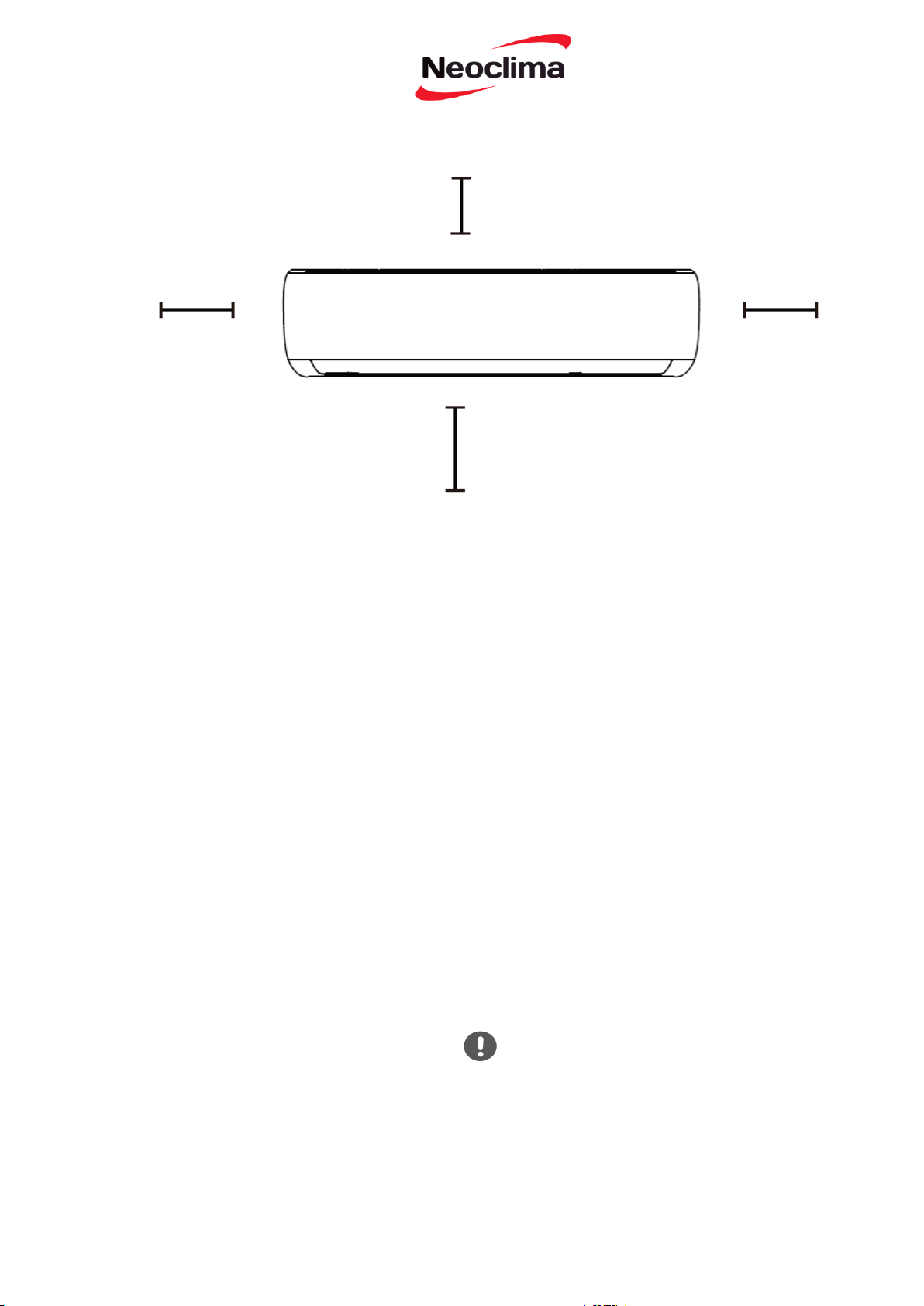
більше)
Зверніться до наступної діаграми, щоб забезпечити належну відстань від стін та стелі:
15 см (5,9
дюймів або
12 см (4,75
дюймів або
більше)
12 см (4,75
дюймів або
більше)
2,3 м (90,55
дюймів)
Рис. 4.1
Крок 3: Просвердліть отвір у стіні для сполучного
трубопроводу
Ви повинні просвердлити отвір в стіні для
трубопроводів холодоагенту, дренажної труби, і
сигнального кабелю, який з'єднує внутрішній і
зовнішній блоки.
25

Стіна
Внутрішній бік
Рис. 4.2
Зовнішній бік
Розміри монтажної пластини
Різні моделі мають різні монтажні пластини.
Для того, щоб переконатися, що у вас є достатньо
місця для встановлення внутрішнього блоку,
діаграми праворуч відображають різні типи
монтажних пластин
з наступними розмірами:
• Ширина монтажної пластини
• Висота монтажної пластини
• Ширина внутрішнього блоку по відношенню до
пластини
• Висота внутрішнього блоку по відношенню до
пластини
• Рекомендоване розташування отворів у стіні (як
ліворуч, так і праворуч від монтажної пластини)
• Відносні відстані між отворами для гвинтів
Правильне положення монтажної пластини
Рис. 4.3
26
Крок 4: Підготовка трубопроводу
холодоагенту
Трубопровід холодоагенту знаходиться
всередині ізолюючої втулки, прикріпленої до
задньої панелі пристрою. Ви повинні
підготувати трубопровід до його
проходження через отвір у стіні. Зверніться
до розділу «Під’єднання трубопроводу
холодоагенту» у даному Посібнику за
інструкціями з розводки труби і вимогами,
методами крутного моменту і т. д.
Примітка щодо коліна труби
Трубопровід холодоагенту може виходити з
внутрішнього блоку з чотирьох різних кутів:
• Ліва сторона
• Ліва задня сторона
• Права сторона
• Права задня сторона
Див Рис. 4.4 для докладної інформації.
Крок 6. Зніміть кронштейн або клин, який підпирає
ізоляційною стрічкою.
Крок 7. Прикладаючи рівномірний тиск, натисніть
на нижню половину блоку. Продовжуйте
натискання поки прилад не встане на гачки вздовж
нижньої частини монтажної пластини.
Якщо вбудованих у стіну труб з холодоагентом
немає, зробіть наступне:
1. Відповідно до положення отвору в стіні по
відношенню до монтажної пластини оберіть
сторону, з якої трубопровід виходить з блоку.
2. Якщо отвір у стіні знаходиться позаду приладу,
не змінюйте положення панелі. Якщо отвір
стіни знаходиться збоку внутрішнього блоку,
зніміть пластикову заглушку з цього боку.
(Див. Рис. 3.3).
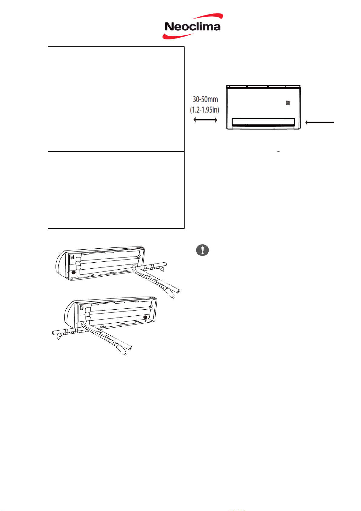
Якщо трубопровід з холодоагентом вже
вбудований в стіну, зробіть наступне:
Крок 1: Встановіть внутрішній блок на
монтажну пластину:
Майте на увазі, що гачки на встановленій
пластині менше, ніж отвори на задній панелі
пристрою. У разі виявлення недостатності
місця для під’єднання
вбудованих труб до внутрішнього блоку,
положення блоку можна скоригувати вліво або
вправо приблизно на 30-50 мм (1.25-1.95 дюймів),
залежно від моделі. (див Рис.4.5):
30 – 50 мм
(1,2-1,95
дюйма)
Перемістити вліво або
вправо
Крок 3. Під’єднайте дренажний шланг і
трубопроводи холодоагенту (див. розділ
«Під’єднання трубопроводу холодоагенту» цього
Посібника для отримання інструкцій).
Крок 4. Точка під’єднання труби має бути
відкритою для проведення тесту на протікання
(див. розділ «Перевірка електричного обладнання і
протікань» цього Посібника).
Крок 5. Після перевірки
протікань, оберніть місце
з'єднання ізоляційною стрічкою.
Будьте вкрай обережні, щоб не пошкодити
або пом’яти трубопровід при його згинанні
від приладу. Будь які вм'ятини в
трубопроводі будуть впливати на
продуктивність роботи приладу.
Рис. 4.5
Рис. 4.4
27

Внаслідок цього утвориться щілина, через
яку ваш трубопровід може вийти з блоку.
Використовуйте гострогубці, якщо
пластикову заглушку занадто важко
видалити вручну.
4. Під’єднайте трубопровід холодоагенту
внутрішнього блоку до сполучної труби, яка
з’єднує внутрішній і зовнішній блоки. Зверніться
до розділу «Під’єднання трубопроводу
холодоагенту» цього Посібника для докладних
інструкцій.
5. Відповідно до положення отвору у стіні відносно
монтажної пластини, визначте необхідний нахил
вашого трубопроводу.
6. Стисніть трубопровід холодоагенту біля основи
згину.
7. Повільно, рівномірно надавлюючи, зігніть
трубопровід у бік отвору. Не залишайте вм'ятин або
пошкоджень трубопроводу.
3. Використовуйте ножиці, щоб обрізати
довжину ізоляційної трубки, з метою дістати
приблизно 15 см (6 дюймів) у трубопроводі
холодоагенту. Це потрібно для двох цілей:
• Для полегшення процесу з'єднання
трубопроводу холодоагенту.
• Для полегшення перевірки протікання газу
і перевірки на наявність вм'ятин.
Крок 5. Під’єднання дренажного
шлангу
За замовчуванням дренажний шланг
кріпиться до лівої сторони блоку (коли
ви обличчям до спинки приладу). Однак,
він також може бути прикріплений до
правої сторони.
1. Для забезпечення належного дренажу
прикріпіть дренажний шланг на тій же
стороні, на якій трубопровід
холодоагенту виходить з блоку.
2. Під’єднайте дренажний шлангподовжувач (купується окремо) до кінця
дренажного шлангу.
3. Оберніть туго точку під’єднання
тефлоновою стрічкою, щоб забезпечити
гарне ущільнення і запобігти
протіканню.
4. Частину дренажного шлангу, який
залишиться в приміщенні оберніть
пінопластовою ізоляцією для труб, щоб
запобігти утворенню конденсату.
5. Зніміть повітряний фільтр і налийте
невелику кількість води в дренажний
піддон, щоб переконатися, що вода
плавно витікає з блоку.
Рис. 3.3
Відрізна
панель
ЗАКУПОРІТЬ НЕВИКОРИСТОВУВАНИЙ
ДРЕНАЖНИЙ ОТВІР
Для запобігання небажаних витоків необхідно
закупорити невикористаний дренажний отвір
гумовою втулкою із комплекту.
НЕПРАВИЛЬНО
Перекручення у
дренажному шлангу
створюють водяні
затвори
28

Примітка для
прокладення
дренажного
шлангу
Переконайтеся, що дренажний шланг
прокладений відповідно до Рис. 3.5.
НЕ
перекручуйте
дренажний
шланг.
НЕ створюйте
водяний затвор
НЕ опускайте
кінець
дренажного
шлангу у воду
або контейнер
для збору води.
ЗАСТЕРЕЖЕННЯ
ПЕРЕД ВИКОНАННЯМ БУДЬ-ЯКОЇ
ЕЛЕКТРИЧНОЇ АБО
ЕЛЕКТРОМОНТАЖНОЇ РОБОТИ,
ВИМКНІТЬ ЕЛЕКТРОМЕРЕЖУ.
6. При підключенні живлення до стаціонарної
проводки у ній потрібно встановити вимикач або
роз’єднувач, який від'єднує усі полюси і має
відстань між контактами принаймні 1/8 дюймів (3
мм). Кваліфікований фахівець повинен
використовувати роз’єднувач.
дренажного шланга у воду або
контейнер для збору води.
Це завадить належному
ПЕРЕД ВИКОНАННЯМ
ЕЛЕКТРИЧНИХ РОБІТ
ОЗНАЙОМТЕСЬ З ЦИМИ
ПРАВИЛАМИ
1. Вся електропроводка повинна відповідати
місцевим і державним електротехнічним нормам і
повинна бути встановлена кваліфікованим
електриком.
2. Всі електричні з'єднання повинні бути зроблені
відповідно до Схеми електричних з’єднань, яка
вказана на панелях внутрішнього і зовнішнього
блоків.
НЕПРАВИЛЬНО
Перекручення у дренажному
шлангу створюють водяні
затвори
НЕПРАВИЛЬНО
Не поміщуйте кінець
стіканню
7. Або підключіть пристрій до окремого
виходу електричного контуру. Не
підключайте інші прилади до цієї розетки.
8. Переконайтесь у правильному
заземленні кондиціонера.
9. Кожен провід повинен бути надійно
підключений. Ненадійна проводка може
призвести до перегріву сполучної коробки,
у результаті чого виріб може вийти з ладу і
може виникнути пожежа.
3. Якщо є серйозна проблема безпеки для блоку
живлення, негайно припиніть роботу. Поясніть
ваші міркування клієнту, і відмовитесь
встановлювати прилад до моменту належного
вирішення питання безпеки.
4. Напруга живлення повинна бути у межах 90100% від номінальної напруги. Недостатня
напруга живлення може спричинити виникнення
несправності, ураження електричним струмом
або пожежу.
5. При підключенні живлення до стаціонарної
проводки встановіть мережевий фільтр і
головний вимикач живлення з потужністю в 1,5
рази більше максимального струму блоку.
10. Не дозволяйте проводці зачіпати або
упиратись у трубки холодоагенту,
компресора або рухомих частин всередині
блоку.
11. Якщо пристрій має допоміжний
електричний нагрівач, він повинен бути
встановлений, принаймні 1 метр (40
дюймів) від будь-яких горючих матеріалів.
29

Електрична схема кондиціонера (РСВ)
передбачає у своєму складі запобіжник, щоб
забезпечити захист від надмірного
електричного струму. Характеристики
запобіжника надруковані на платі
керування , вони є наступними: T3.15A /
250VAC, T5A / 250VAC, і т. д.
ЗАСТЕРЕЖЕННЯ
4. Відгвинтіть затискач кабелю під клемною
колодкою і покладіть його вбік.
5. Стоячи обличчям до задньої частини блоку,
зніміть пластикову панель на дні лівої сторони.
6. Протягніть сигнальний дріт через цю щілину, із
задньої частини приладу у передню.
ВСЯ ПРОВОДКА ПОВИННА БУТИ
ВИКОНАНА СТРОГО У ВІДПОВІДНОСТІ
ЗІ СХЕМОЮ, ЯКА ЗНАХОДИТЬСЯ
ВСЕРЕДИНІ КРИШКИ ПРОВОДКИ
ВНУТРІШНЬОГО БЛОКУ.
Крок 6: Під’єднайте сигнальний кабель
Сигнальний кабель забезпечує зв'язок між
внутрішнім і зовнішнім блоками. Ви
повинні спочатку вибрати правильний
розмір кабелю перед його підготовкою для
під’єднання.
Типи кабелів
електропроводки
• Внутрішній кабель живлення (якщо такий
застосовується):
H05VV-F або F-H05V2V2
• Зовнішній кабель живлення: H07RN-F
• Сигнальний кабель: H07RN-F
Мінімальна площа поперечного перерізу з
силових і сигнальних кабелів
Північна Америка
Сила струму у
приладі (А)
Американська
система товщини
дротів
10 18
13 16
18 14
25 12
30 10
Інші регіони
Номінальний струм
приладу
Номінальний
перетин
> 3 і ≤6 0.75
> 6 і ≤10 1
> 10 і ≤16 1,5
> 16 і ≤25 2,5
> 25 і ≤32 4
> 32 і ≤40 6
ВИБЕРІТЬ ПРАВИЛЬНИЙ РОЗМІР
КАБЕЛЮ
Розмір кабелю живлення, сигнального
кабелю, запобіжника і необхідний
перемикач визначаються максимальним
струмом блоку. Максимальний струм
вказаний на табличці на бічній панелі
приладу. Ознайомтесь з цією табличкою,
щоб правильно вибрати кабель, запобіжник,
або перемикач.
ОЗНАЙОМТЕСЬ З ТЕХНІЧНИМИ
ХАРАКТЕРИСТИКАМИ ЗАПОБІЖНИКА
1. Підготуйте кабель для під’єднання:
а. Використовуючи кліщі для зачистки
дротів, зніміть гумову ізоляцію з обох кінців
сигнального кабелю приблизно на 15 см (6
дюймів).
б. Зніміть ізоляцію з кінців проводів.
в. Використовуючи обтискні щипці,
обтисніть наконечники U-типу на кінцях
проводів.
ЗВЕРНІТЬ УВАГУ НА ДРІТ ПІД СТРУМОМ
Під час обтиску дротів переконайтеся, що ви чітко
розрізнили дріт під струмом (L) від інших дротів
2. Відкрийте передню панель внутрішнього блоку
та ослабте гвинти відповідно до зображення на
Рис.3.9, які забезпечують більше простору для
під’єднання дротів.
3. Відкрийте кришку розподільчої коробки для
під’єднання кабелю.
Кришка
Затискач
кабелю
Схема електропроводки
знаходиться всередині кришки
електропроводки внутрішнього
30
7. Стоячи обличчям до передньої частини
блоку, підберіть кольори дротів до міток на
клемній колодці, підключіть U-наконечник і
закрутіть міцно кожен дріт на відповідній
клемі.
НЕ ПЕРЕПЛІТАЙТЕ СИГНАЛЬНИЙ КАБЕЛЬ
З ІНШИМИ
Під час зв’язування цих елементів разом, не
переплітайте або не перетинайте сигнальний
кабель з іншими дротами.
2. За допомогою клейкої вінілової стрічки,
прикріпіть дренажний шланг до нижньої
частини труб з холодоагентом.
3. За допомогою ізоляційної стрічки оберніть
щільно разом сигнальний кабель, труби
холодоагенту і дренажний шланг. Двічі
перевірте, що всі елементи зв’язані відповідно
до Рис. 3.12.
ПОПЕРЕДЖЕННЯ
НЕ ПЕРЕПЛУТАЙТЕ ФАЗУ І НУЛЬ
Це небезпечно, і може призвести до виходу з
ладу кондиціонеру повітря.
8. Після перевірки безпечності кожного
з'єднання за допомогою кабельного затискача
прикріпіть сигнальний кабель до приладу.
Щільно закрутить гвинт кабельного затискача.
9. Закрийте кришку на передній панелі приладу
і пластикову панель на задній стороні.
НЕ ЗАГОРТАЙТЕ КІНЦІ ТРУБОПРОВОДІВ
Під час загортання залишайте кінці
трубопроводів вільними. Вам потрібен доступ
до них, щоб перевірити на предмет протікання в
кінці процесу встановлення (див. розділ
«Перевірки електричних частин і герметичності
даного посібника).
ПРИМІТКА ДО
ЕЛЕКТРОПРОВОДКИ
ПРОЦЕС ПІДКЛЮЧЕННЯ ПРОВОДКИ
МОЖЕ ДЕЩО ВІДРІЗНЯТИСЯ, ЗАЛЕЖНО
ВІД ПРИЛАДУ.
Крок 8: Монтаж внутрішнього блоку.
Якщо ви встановили на зовнішньому блоці нову
сполучну трубу, виконайте такі дії:
1. Якщо ви вже проклали трубу з
холодоагентом через отвір в стіні, перейдіть до
кроку 4.
2. В іншому випадку, двічі перевірте
герметичність кінців труб з холодоагентом для
запобігання забрудненню або попадання
чужорідних матеріалів.
3. Повільно просуньте згорток з труб
холодоагенту, дренажного шлангу і
сигнального кабелю через отвір в стіні.
4. Зачепіть верхню частину внутрішнього блоку
за верхній гачок монтажної пластини.
5. Переконайтеся, що пристрій міцно
тримається на гачку, злегка натиснувши на ліву
і праву сторони блоку. Прилад не слід
похитувати або зрушувати.
6. Рівномірно натисніть на нижню половину
блоку. Тримайте натиснувши поки пристрій не
встане на гачки вздовж нижньої частини
монтажної пластини.
7. Знову переконайтеся, що пристрій надійно
встановлений злегка натиснувши на ліву і праву
сторони приладу.
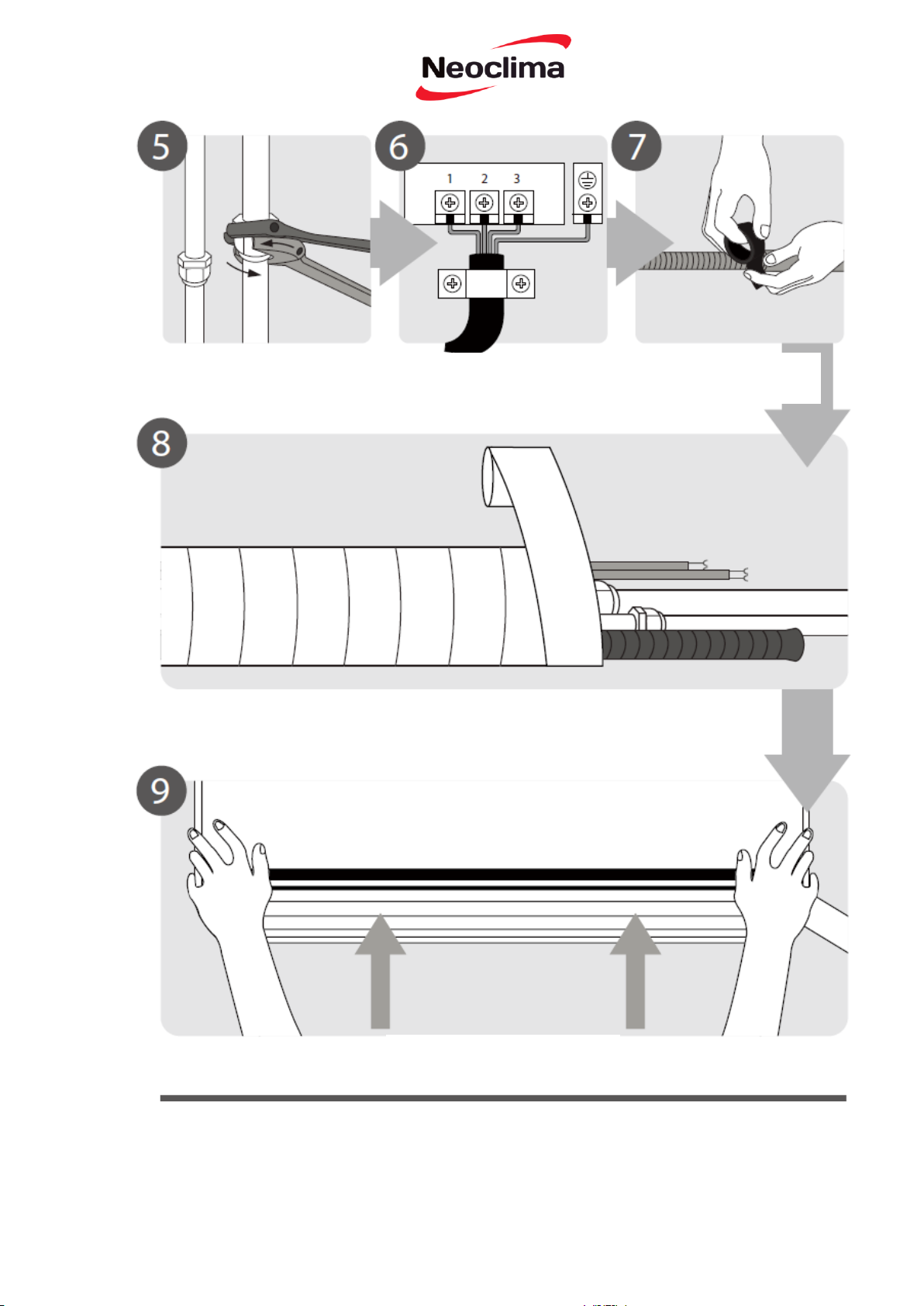
Крок 7: Оберніть трубопроводи та кабелі
перед проходженням трубопроводу,
дренажного шлангу і сигнального кабелю через
отвір у стіні, ви повинні зв'язати їх разом, щоб
зекономити простір, захистити та ізолювати їх.
1. Зв'яжіть дренажний шланг, труби для
холодоагенту і сигнальний кабель відповідно до
Рис. 3.12.
ДРЕНАЖНИЙ ШЛАНГ ПОВИНЕН БУТИ
НА ДНІ
Переконайтеся, що дренажний шланг
знаходиться в нижній частині пучка. Введення
дренажного шлангу у верхню частину пучка
може викликати переповнення піддону, яке
може призвести до пожежі або пошкодження
водою.
Сигнальний
кабель
Внутрішній блок
Дренажний
шланг
Простір
позаду
блоку
Трубопровід
холодоагенту
Ізоляційна
стрічка
Рис. 3.12
31
Інструкція для встановлення зовнішній блок
Крок 1: Оберіть місце установки
Перед встановленням зовнішнього блоку
вам потрібно вибрати відповідне місце.
Нижче наведені стандарти, які
допоможуть вам вибрати відповідне місце
для приладу.
Належне місце встановлення відповідає
наступним стандартам:
НЕ встановлюйте пристрій в наступних місцях:
Відповідає всім вимогам до
простору, які відображені у
Вимогах до простору при
встановленні (Рис. 4.1)
Поруч з будь-якою перешкодою, що може
блокувати циркуляцію повітря
Добра циркуляція повітря і
вентиляція
Поблизу вулиці загального користування,
місць скупчення людей або там, де шум від
блоку буде заважати іншим людям
Міцне і тверде місце - може
підтримувати пристрій і не вібрує
Поруч з тваринами або рослинами, які
будуть постраждали від гарячого повітря
Шум від блоку не заважає іншим
людям
Поруч будь-якого джерела горючого газу
Захист від тривалого впливу
прямих сонячних променів або
дощу
У надто запиленому місці
У місці з надмірним рівнем солоного повітря
Рис. 4.1
Встановлення зовнішнього блоку
Рис. 4.1
32
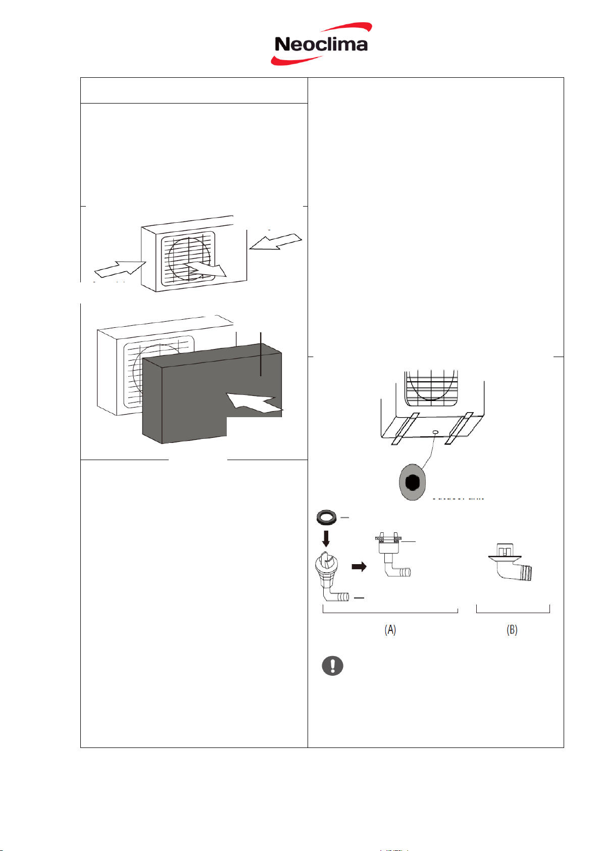
ОСОБЛИВІ ЗАУВАЖЕННЯ ЗА
ЕКСТРЕМАЛЬНИХ ПОГОДНИХ УМОВ
Якщо прилад піддається впливу сильного
вітру:
Встановіть блок таким чином, щоб отвір для
випуску повітря вентилятора був під кутом
90 ° до напрямку вітру. За необхідності
облаштуйте бар'єр спереду приладу, щоб
захистити його від надмірно сильного вітру.
Див. рис. 4.2 і рис. 4.3 нижче.
У умовах холодного клімату, встановіть
дренажний шланг якомога вертикальніше, щоб
забезпечити швидке відведення води. Якщо вода
стікає занадто повільно, вона може замерзнути в
шлангу і затопити блок.
Якщо прилад часто знаходиться під сильним
дощем або снігом:
Облаштуйте укриття над блоком, щоб
захистити його від дощу або снігу. Будьте
обережні, щоб не створювати перешкоди
повітряному потоку навколо пристрою.
Якщо на прилад часто впливає солоне
повітря (на морському побережжі):
Використовуйте зовнішній блок, який
спеціально спроектований із захистом від
корозії.
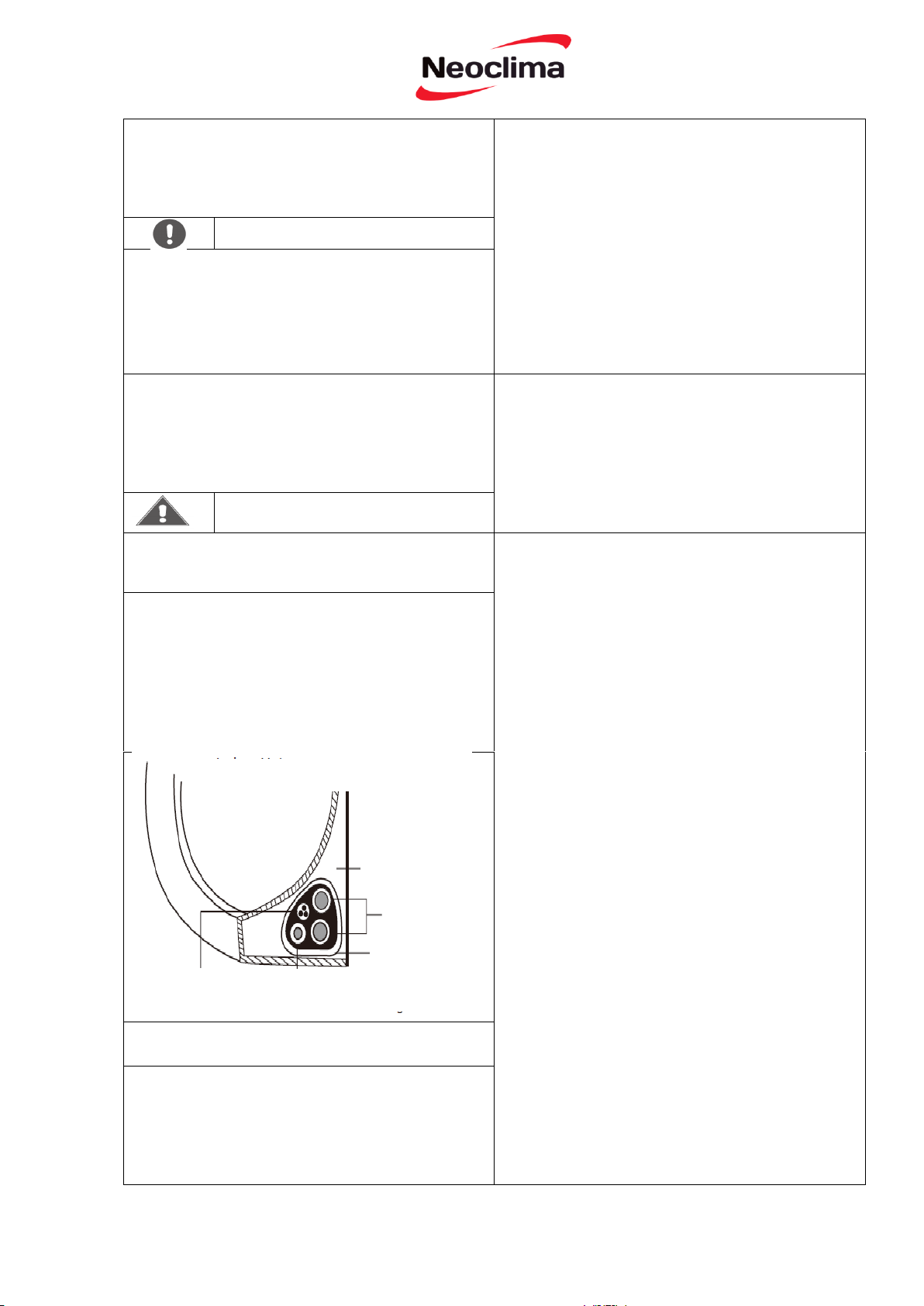
Крок 2: Встановіть дренажне коліно
Теплові насосні агрегати вимагають
встановлення дренажного коліна. До
моменту кріплення зовнішнього блоку
болтами до місця, ви повинні встановити
дренажне коліно в нижній частині приладу.
Зверніть увагу, що є два типи дренажних
з'єднань в залежності від типу зовнішнього
блоку.
Сильний вітер
Рис. 4.2
Сильний вітер
Вітрозахисний
екран
Якщо дренажне коліно постачається з гумовим
ущільненням (рис 4.4 - А.), виконайте такі дії:
1. Встановіть гумове ущільнення на кінці
дренажного коліна, які будуть під’єднане до
зовнішнього блоку.
2. Вставте дренажне коліно в отвір у піддоні блоку.
3. Поверніть дренажне коліно на 90° до тих пір,
поки не стане на місце спереду блоку.
4. Під’єднайте подовжувач дренажного шлангу (не
входить в комплект) до дренажного коліна, щоб
перенаправити воду з агрегату під час режиму
нагріву.
Якщо гумове ущільнення не постачається разом з
дренажним коліном (рис 4.4 - B), виконайте такі
дії:
1. Вставте дренажне коліно в отвір у піддоні блоку.
Дренажне коліно стане на місце.
2. Під’єднайте подовжувач дренажного шлангу (не
входить в комплект) до дренажного коліна, щоб
перенаправити воду з агрегату під час режиму
нагріву.
Рис. 4.3
Сильний вітер
Основний отвір
зовнішнього блоку
Ущільнювач
Ущільнювач
Дренажне коліно
Рис. 4.4
В УМОВАХ ХОЛОДНОГО
КЛІМАТУ
33
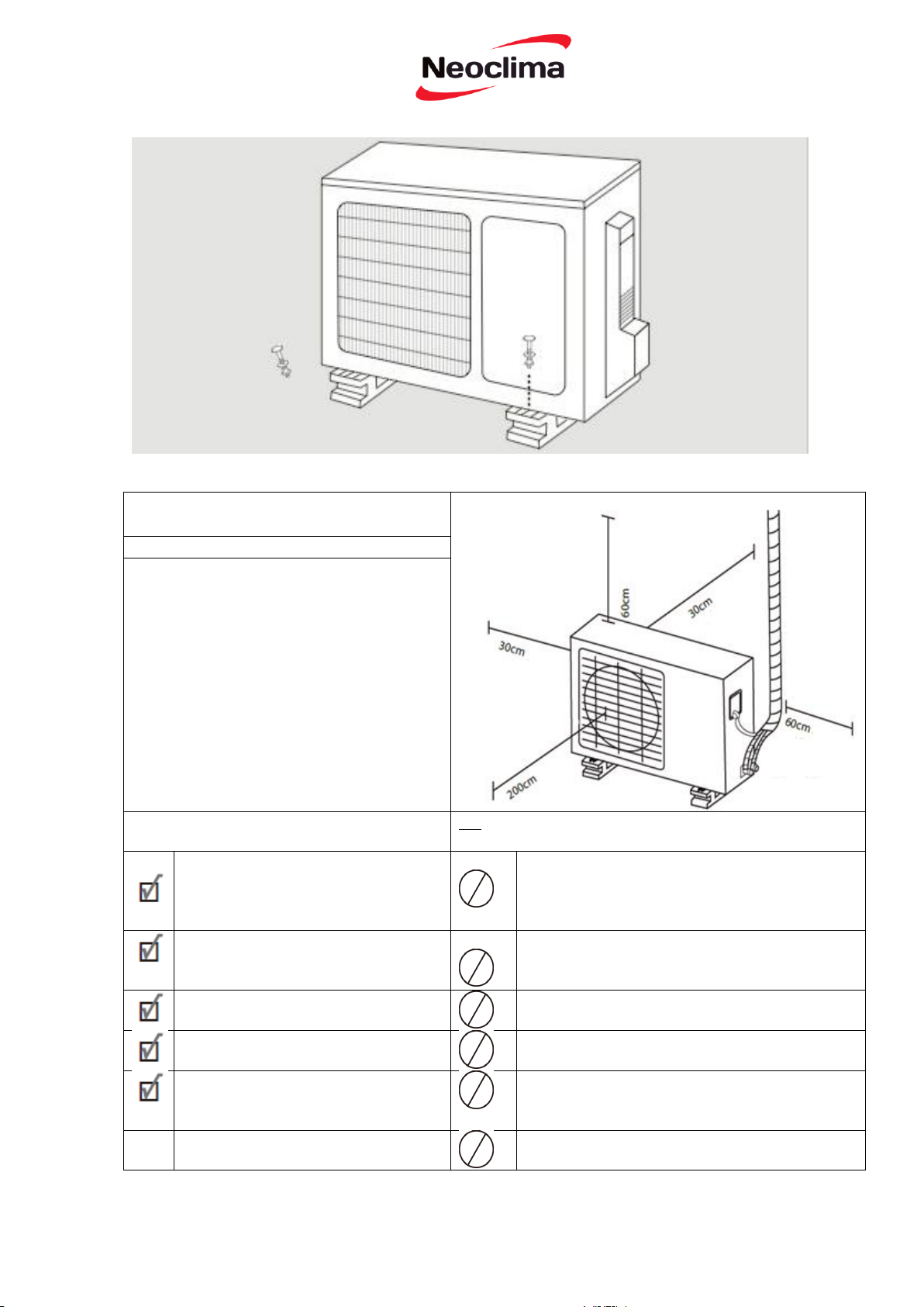
Крок 3: Закріплення зовнішнього
блоку
Зовнішній блок може бути прикріплений до
землі або кронштейном до стіни.
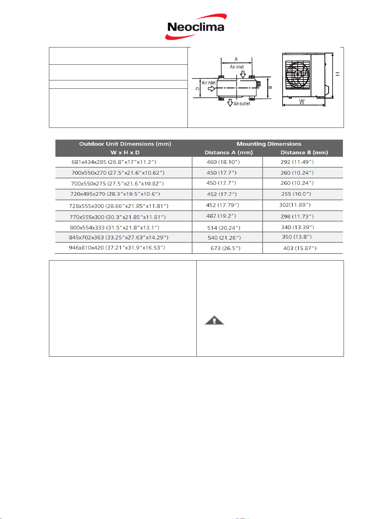
МОНТАЖНІ РОЗМІРИ БЛОКУ
Нижче приведений список різних розмірів
зовнішніх блоків і відстань між їх
монтажними ніжками. Підготуйте основу
для встановлення блоку відповідно до
розмірів, наведених нижче.
Розміри зовнішнього блоку
Монтажні розміри
Ш х В х Г
Відстань А
Відстань В
681x434x285 (26.8”x17”x11.2”)
460 (18.10”)
292 (11.49”)
700x550x270 (27.5”x21.6”x10.62”)
450 (17.7”)
260 (10.24”)
780x540x250 (30.7”x21.25”x9.85”)
549 (21.6”)
276 (10.85”)
845x700x320 (33.25”x27.5”x12.6”)
335 (13.2”)
810x558x310 (31.9”x22”x12.2”)
325 (12.8”)
700x550x275 (27.5”x21.6”x10.82”)
260 (10.24”)
770x555x300 (30.3”x21.85”x11.81”)
298 (11.73”)
800x554x333 (31.5”x21.8”x13.1”)
340 (13.39”)
845x702x363 (33.25”x27.63”x14.29”)
350 (13.8”)
900x860x315 (35.4”x33.85”x12.4”)
333 (13.1”)
945x810x395 (37.2”x31.9”x15.55”)
405 (15.95”)
946x810x420 (37.21”x31.9”x16.53”)
403 (15.87”)
946x810x410 (37.21”x31.9”x16.14”)
403 (15.87”)
Якщо ви будете встановлювати прилад на землі
або на бетонній монтажній платформі,
виконайте такі дії:
1. Відмітьте місця для чотирьох розпірних
болтів відповідно до розмірів на схемі
«Монтажні розміри блоку».
2. Попередньо просвердліть отвори для болтів.
3. Очистіть отвори від бетонного пилу.
4. Встановіть гайку на кінці кожного розпірного
болта.
5. Забийте молотком розпірні болти у
попередньо просвердлені отвори.
6. Зніміть гайки з розпірних болтів розширення
і помістіть зовнішній блок на болти.
7. Натягніть шайби на кожен розпірний болт, а
потім поверніть гайки на місце.
8. За допомогою гайкового ключа, затягніть
кожну гайку до упору.
ПІД ЧАС СВЕРДЛІННЯ У БЕТОНІ
РЕКОМЕНДУЮТЬСЯ ВЕСЬ ЧАС
ВИКОРИСТОВУВАТИ ЗАСІБ ДЛЯ ЗАХИСТУ
ОЧЕЙ
Рис. 4.5
560 (22”)
549 (21.6”)
450 (17.7”)
487 (19.2”)
514 (20.24”)
540 (21.26”)
590 (23.2”)
640 (25.2”)
673 (26.5”)
673 (26.5”)
ЗАСТЕРЕЖЕННЯ
34
Якщо ви будете встановлювати прилад на
настінному кронштейні, зробіть наступне:
ПЕРЕД ВИКОНАННЯМ
ЕЛЕКТРИЧНИХ РОБІТ
ОЗНАЙОМТЕСЬ З ЦИМИ
ПРАВИЛАМИ
ПОПЕРЕДЖЕННЯ
1. Вся електропроводка повинна відповідати
місцевим і державним електротехнічним
нормам і повинна бути встановлена
кваліфікованим електриком.
2. Всі електричні з'єднання повинні бути
зроблені відповідно до Схеми електричних
з’єднань, яка вказана на панелях внутрішнього і
зовнішнього блоків.
3. Якщо є серйозна проблема безпеки для блоку
живлення, негайно припиніть роботу. Поясніть
ваші міркування клієнту, і відмовтесь
встановлювати прилад до моменту належного
вирішення питання безпеки.
4. Напруга живлення повинна бути у межах 90100% від номінальної напруги. Недостатня
напруга живлення може спричинити
виникнення несправності, ураження
електричним струмом або пожежі.
5. При підключенні живлення до стаціонарної
проводки встановіть мережевий фільтр і
головний вимикач живлення з потужністю в 1,5
рази більше максимального струму блоку.
6. При підключенні живлення до стаціонарної
проводки у ній потрібно встановити вимикач
або роз’єднувач, який від'єднує усі полюси і має
відстань між контактами принаймні 1/8 дюймів
(3 мм). Кваліфікований фахівець повинен
використовувати роз’єднувач.
7. Або підключіть пристрій до окремого виходу
електричного контуру. Не підключайте інші
прилади до цієї розетки.
8. Переконайтесь у правильному заземленні
кондиціонера.
9. Кожен провід повинен бути надійно
підключений. Ненадійна проводка може
призвести до перегріву сполучної коробки, у
результаті чого виріб може вийти з ладу і може
виникнути пожежа.
10. Не дозволяйте проводці зачіпати або
упиратись у трубки холодоагенту, компресора
або рухомих частин всередині блоку.
11. Якщо пристрій має допоміжний
електричний нагрівач, він повинен бути
встановлений, принаймні 1 метр (40 дюймів) від
будь-яких горючих матеріалів.
Перед настінним монтажем блоку
переконайтесь, що стіна зроблена з твердої
цегли, бетону або аналогічного міцного
матеріалу. Стіна повинна бути здатна
витримувати вагу щонайменше в чотири рази
більшу аніж вага приладу.
1. Відмітьте положення отворів під кронштейни
відповідно до схеми «Монтажні розміри блоку.
2. Попередньо просвердліть отвори для болтів.
3. Очистіть отвори від пилу і осколків.
4. Встановіть гайку на кінці кожного розпірного
болта
5. Загвинтіть розпірні болти через отвори в
монтажних кронштейнах, помістіть монтажні
кронштейни в потрібне положення і забийте
розпірні болти молотком у стіну.
6. Переконайтеся, що монтажні кронштейни
знаходяться на одному рівні.
7. Обережно підніміть прилад і помістіть його
монтажні ніжки на кронштейни.
ЗМЕНШЕННЯ ВІБРАЦІЇ БЛОКУ,
ВСТАНОВЛЕНОГО НА СТІНУ
Якщо є можливість, можна встановити
настінний блок з гумовими прокладками для
зниження вібрації і шуму.
Крок 4: Під’єднання сигнального кабелю
і кабелю живлення
Клемний блок зовнішнього блоку захищений
кришкою електричної проводки збоку приладу.
Схема підключення надрукована на внутрішній
стороні кришки.
35

ЗАСТЕРЕЖЕННЯ
ЗВЕРНІТЬ УВАГУ НА ДРІТ ПІД СТРУМОМ
Під час обтиску дротів переконайтеся, що ви чітко
розрізнили дріт під струмом (L) від інших дротів.
ПЕРЕД ВИКОНАННЯМ БУДЬ-ЯКОЇ
ЕЛЕКТРИЧНОЇ АБО
ЕЛЕКТРОМОНТАЖНОЇ РОБОТИ,
ВИМКНІТЬ ЕЛЕКТРОМЕРЕЖУ.
ЗАСТЕРЕЖЕННЯ
1. Підготуйте кабель з’єднання
ВИКОРИСТОВУЙТЕ ПРАВИЛЬНИЙ
КАБЕЛЬ
• Внутрішній кабель живлення (якщо такий
застосовується): H05VV-F або H05V2V2-F
• Зовнішній кабель живлення: H07RN-F
• Сигнальний кабель: H07RN-F
Мінімальна площа поперечного перерізу
силових і сигнальних кабелів
Північна Америка
Інші регіони
7. Ізолювати не використовувані дроти за
допомогою ізоляційної стрічки ПВХ. Прокладіть їх
так, щоб вони не торкалися будь-яких електричних
або металевих частин.
8. Поверніть кришку електропроводки на місце
збоку приладу і закріпіть її гвинтом.
а. Використовуючи кліщі для зачистки
дротів, зніміть гумову ізоляцію з обох кінців
сигнального кабелю приблизно на 15 см (6
дюймів).
б. Зніміть ізоляцію з кінців проводів.
в. Використовуючи обтискні щипці,
обтисніть наконечники U-типу на кінцях
проводів.
Рис. 4.6
зовнішнього блоку
Сила струму у
приладі (А)
Американська
система товщини
дротів
10 18
13 16
18 14
25 12
30 10
ВСЯ ПРОВОДКА ПОВИННА БУТИ ВИКОНАНА
СТРОГО У ВІДПОВІДНОСТІ ЗІ СХЕМОЮ, ЯКА
ЗНАХОДИТЬСЯ ВСЕРЕДИНІ КРИШКИ
ПРОВОДКИ ВНУТРІШНЬОГО БЛОКУ.
2. Відгвинтіть кришку електричної проводки і
зніміть її.
3. Відгвинтіть затискач кабелю під клемною колодкою і
покладіть його вбік.
4 Підберіть кольори дротів до міток на клемній
колодці, підключіть U-наконечник і закрутіть
міцно кожен дріт на відповідній клемі.
5. Після перевірки безпеки кожного з'єднання оберніть
дріт навколо, щоб запобігти попаданню дощової води у
клемну коробку.
6. За допомогою кабельного затискача прикріпіть
кабель до пристрою. Щільно загвинтити кабельний
затискач.
Номінальний струм
приладу
Номінальний
перетин
> 3 і ≤6 0.75
> 6 і ≤10 1
> 10 і ≤16 1,5
> 16 і ≤25 2,5
> 25 і ≤32 4
> 32 і ≤40 6
Кришка
Схема електропроводки знаходиться
всередині кришки електропроводки
36
Модель
Макс. Перепад висот (м)
Інверторний
кондиціонер з
однією сплітсистемою
10 (33 футів)
20 (66 футів)
≥24,000 і < 36000
25 (82 футів)
≥36000 і ≤60000
30 (98.5 футів)
Інструкції для під’єднання трубопровід з холодоагентом
2. За допомогою труборізу, відрізати трубу трохи
довше, ніж виміряна відстань
Крок 1: Обрізання труб
Під час підготовки труб з холодоагентом
потрібно бути дуже обережним, щоб
обрізати і розширити їх належним чином. Це
буде запорукою ефективної роботи і
мінімізує необхідність технічного
обслуговування в майбутньому.
1. Виміряйте відстань між внутрішнім і
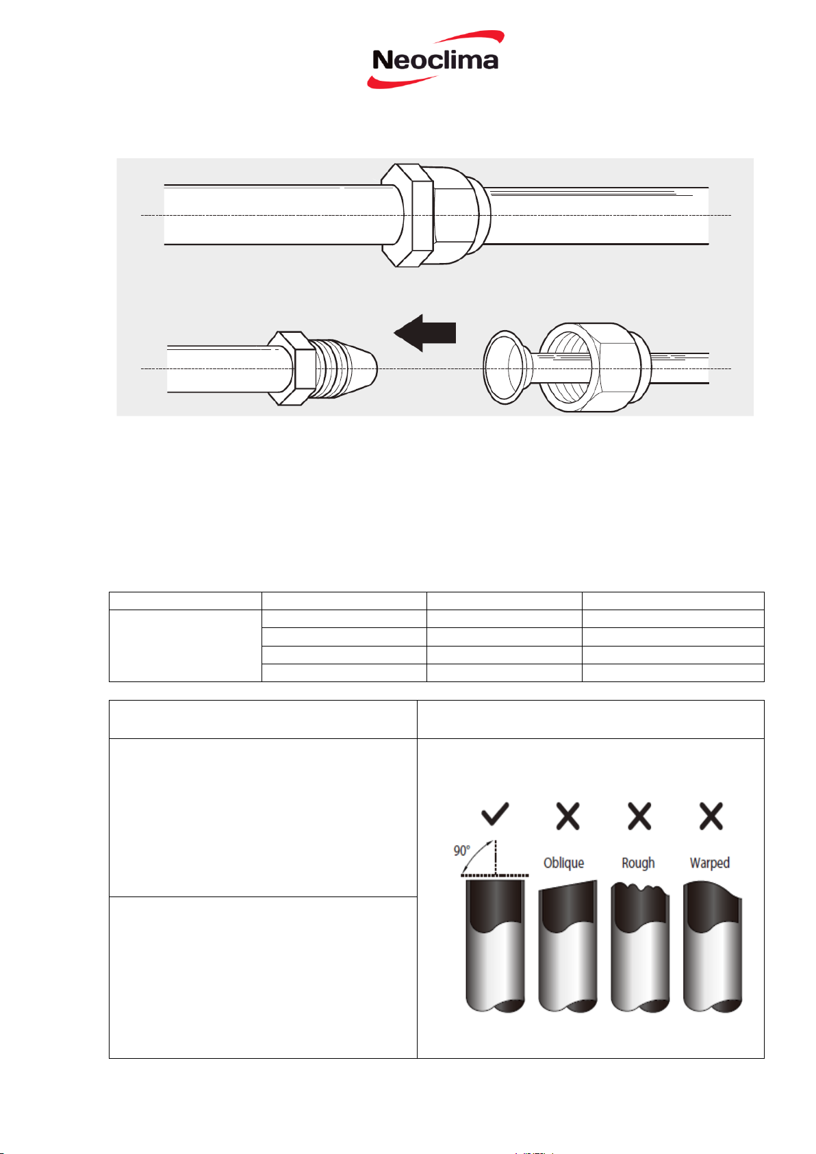
зовнішнім блоками.
3. Переконайтеся, що труба обрізується точно на
кут 90°. Див. Рис. 5.1 для незадовільних прикладів
обрізання.
З’єднання трубопроводу з холодоагентом
Примітка щодо довжини трубопроводу
Довжина трубопроводу з холодоагентом буде впливати на продуктивність та енергоефективність
блоку. Номінальна ефективність перевіряється на приладах з трубопроводом довжиною до 5
Зверніться до таблиці нижче для специфікацій на максимальну довжину і висоту падіння
Довжина і перепад висот трубопроводу з холодоагентом на модель приладу
Потужність (БТЕ/год.) Мін. та Макс. довжина
< 15000
≥15000 і < 24000
метрів (16.5 футів).
трубопроводу.
3 - 25 метрів
5 -
7 7 -
30 метрів
50 метрів
65 метрів
Рис. 5.1
37

НЕ ДЕФОРМУЙТЕ ТРУБУ ПІД
ЧАС РІЗАННЯ
Будьте особливо обережні, щоб не пошкодити,
не зробити вм'ятину або не деформувати
трубу під час різання. Це різко знижує
ефективність приладу у режимі нагріву.
Крок 2: Видаліть задирки
4. Зніміть ПВХ стрічку з кінців труби, коли ви
готові виконати роботу із розширення.
Задирки можуть вплинути на герметичне
ущільнення у місцях з’єднання труб
холодоагенту. Вони повинні бути повністю
вилучені.
5. Прикріпіть форму для розширення на кінці
труби.
Кінець труби повинен виходити за межі кромки
форми відповідно до розмірів, зазначених в
таблиці нижче.
1. Тримайте трубу під ухилом вниз, щоб
запобігти попаданню задирок у трубу.
2. За допомогою розширювача або
інструменту для видалення задирок, видаліть
задирки з обрізаної частини труби.
Крок 3: Розширення кінців труб
ВИСТУП ТРУБОРОВОДУ ЗА МЕЖІ ФОРМИ
ДЛЯ РОЗШИРЕННЯ
Правильне розширення є істотним для
отримання герметичного ущільнення.
Зовнішній
діаметр труби
(мм)
А (мм)
Мін.
Макс.
Ø 6.35 (Ø 0.25”)
0.7 (0.0275”)
1.3 (0.05”)
Ø 9.52 (Ø 0.375”)
1.0 (0.04”)
1.6 (0.063”)
Ø 12.7 ( Ø 0.5”)
1.0 (0.04”)
1.8 (0.07”)
Ø 16 ( Ø 0.63”)
2.0 (0.078”)
2.2 (0.086”)
1. Після зняття задирок з обрізу труби,
закрийте кінці ПВХ стрічкою, щоб запобігти
попаданню чужорідних матеріалів у трубу.
2. Оберніть трубу ізоляційним матеріалом.
3. Встановіть гайки на обох кінцях труби.
Переконайтеся, що вони знаходяться у
правильному напрямку, тому що ви не можете
сполучити або змінити їх напрям після
розширення. Див. Рис. 5.3.
гайка
Мідна труба
Нахил униз
Труба
Очищувач
Рис. 5.3
Рис. 5.4
Рис. 5.2
Форма для розширення
Рис. 5.5
Труба
38
6. Розмістить інструмент для розширення на
формі.
Інструкції для з'єднування трубопроводів
з внутрішнім блоком
7. Поверніть ручку інструменту для
розширення за годинниковою стрілкою до
моменту повного розширення труби.
1. Вирівняйте центр двох труб, які ви будете
з’єднувати. Див рис. 5.7.
8. Зніміть інструмент і форму для розширення,
потім перевірте кінець труби на наявність
тріщин і рівномірність розширення.
Крок 4: З’єднання труб
При з’єднанні труб холодоагенту, будьте
обережні, щоб не докласти надлишковий
крутний момент або деформувати трубопровід
у будь-який спосіб. Ви повинні спочатку
підключити трубу низького тиску, потім трубу
високого тиску.
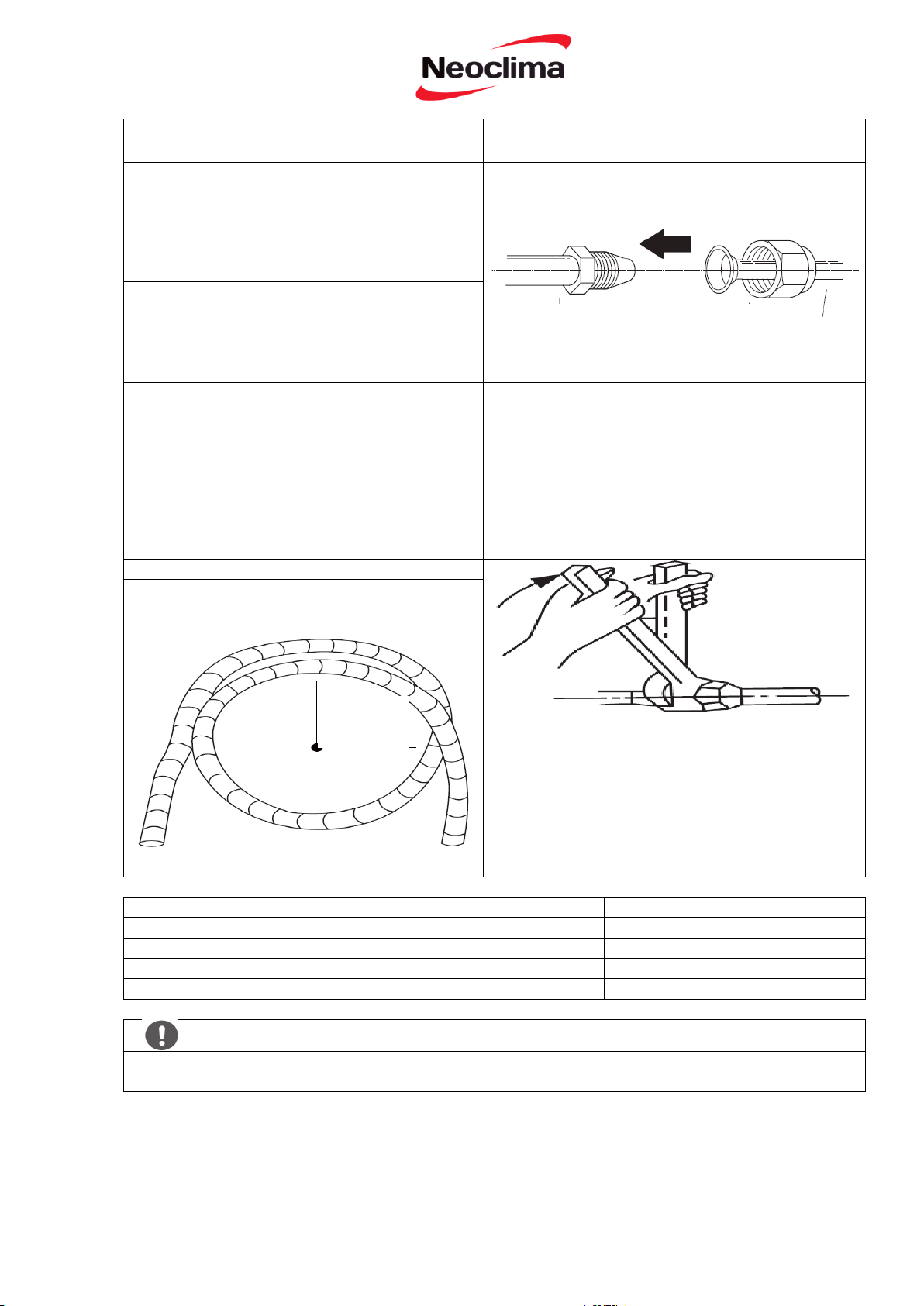
2. Міцно вручну затягнути гайку.
3. За допомогою гайкового ключа, закріпіть гайку
на трубопроводі.
4. Міцно стискаючи штуцер на трубопроводі, за
допомогою гайкового ключа, затягніть гайку
відповідно до значень крутного моменту,
наведених нижче у таблиці «Вимоги до крутного
моменту. Злегка послабити гайку, а потім
затягнути знову.
МІНІМАЛЬНИЙ РАДІУС ЗГИНАННЯ
Під час згинання з'єднувальної труби
холодоагенту, мінімальний радіус згинання
складає 10 см. Див. Рис 5.6
Зовнішній діаметр труби (мм)
Моменти затяжки Нсм
Додаткові моменти затяжки Нсм
Ø 6.35 (Ø 0.25”)
1500 (11 фунтів • футів)
1,600 (11.8 фунтів • футів)
Ø 9.52 (Ø 0.375”)
2500 (18.4 фунтів • футів)
2,600 (19.18 фунтів • футів)
Ø 12.7 ( Ø 0.5”)
3500 (25.8 фунтів• футів)
3,600 (26.55 фунтів• футів)
Ø 16 ( Ø 0.63”)
4500 (33.19 фунтів• футів)
4,700 (34.67 фунтів• футів)
НЕ ПРИКЛАДАЙТЕ НАДМІРНИЙ МОМЕНТ
Надмірне зусилля може зламати гайку або пошкодити трубопровід холодоагенту. Ви не повинні
перевищувати вимоги до моменту, зазначені вище у таблиці.
Радіус
10 см
(4 дюйми)
Трубопровід внутрішнього
блоку
Рис. 5.7
Рис. 5.8
Гайка
Труба
Рис. 5.6
ВИМОГИ ДО КРУТНОГО МОМЕНТУ
39
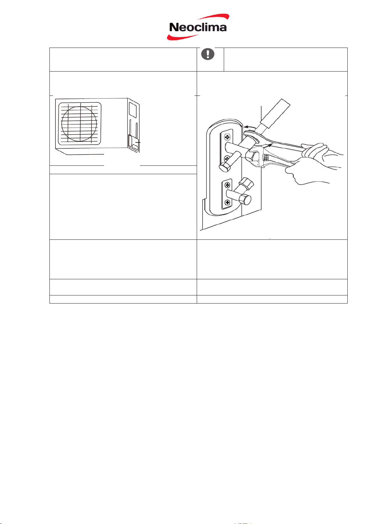
Інструкції для з'єднання трубопроводів
із зовнішнім блоком
ВИКОРИСТОВУЙТЕ ГАЙКОВИЙ
КЛЮЧ ДЛЯ ЗАТИСКАННЯ
КОРПУСУ КЛАПАНА
1. Відгвинтіть кришку сервісного клапана
збоку на зовнішньому блоці. (Рис. 5.9)
Крутний момент від затяжки муфти для
розширення може пошкодити інші частини
клапана.
2. Зніміть захисні ковпачки з кінців арматури.
3. Зіставте розширений кінець труби з кожним
клапаном і затягніть міцно гайку вручну.
4. За допомогою гайкового ключа міцно
стисніть корпус клапана.
Не беріться за гайку, яка герметизує сервісний
клапан. (Рис. 5.10)
6. Злегка послабте гайку, а потім знову
затягніть.
7. Повторіть кроки з 3 по 6 для решти труб.
Рис. 5.9
Кришка клапана
Рис. 5.10
5. Міцно стискаючи корпус клапана, за
допомогою гайкового ключа затягніть гайку
відповідно до правильних значень моменту
затяжки.
40
Підготовка і запобіжні заходи
Повітря і сторонні речовини у контурі
холодоагенту можуть викликати аномальне
підвищення тиску, яке може пошкодити
кондиціонер, знизити ефективність його
роботи, а також призвести до травм.
Використовуйте вакуумний насос і
манометри для очищення холодильного
контуру, видаляючи неконденсований газ і
вологу із системи.
Очищення повинне проводитись при
першому встановленні і після переміщення
блоку.
ДО ПОЧАТКУ ОЧИЩЕННЯ
Переконайтеся, що обидва
трубопроводи високого тиску і
низького тиску між внутрішнім і
зовнішнім блоками правильно
під’єднанні відповідно до розділу
«Під’єднання трубопроводу з
холодоагентом» даного посібника.
Переконайтеся, що всі дроти
правильно підключені.
1. Підключіть заправний шланг манометра до
сервісного порту на клапані низького тиску
зовнішнього блоку.
2. Підключіть інший заправний шланг від
манометра до вакуумного насоса.
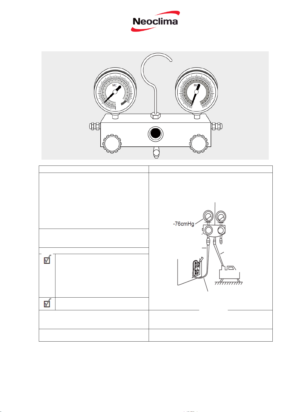
ВИДАЛЕННЯ ПОВІТРЯ
Інструкції для видалення
Перед використанням манометра і вакуумного
насоса ознайомтесь з інструкцією по експлуатації,
щоб правильно їх використовувати.
Манометричний колектор
Сполучений клапан Клапан тиску
Клапан низького тиску
Заправний шланг
низького тиску
Клапан низького тиску
Рис. 6.1
Клапан високого
тиску
Заправний шланг
Вакуумний
насос
41

3. Відкрийте сторону низького тиску в
манометричному колекторі. Не відкривайте
сторону високого тиску.
4. Увімкніть вакуумний насос для
вакуумування системи.
5. Запустіть насос принаймні на 15 хвилин,
або поки лічильник не покаже-76 сантиметрів
ртутного стовпчика (-10 Па).
6. Закрийте сторону низького тиску в
манометричному колекторі і вимкніть
вакуумний насос.
7. Зачекайте 5 хвилин, а потім перевірте, чи не
було яких-небудь змін у системі тиску.
8. Якщо є зміна у тиску системи, зверніться до
розділу «Перевірка витоку газу» за
інформацією про те, як перевірити
герметичність. Якщо немає ніяких змін в
системі тиску, відкрутити ковпачок з
сервісного клапану (клапан високого тиску).
9. Вставте шестигранний ключ у сервісний
клапан (клапан високого тиску) і відкрийте
клапан поворотом ключа на 1/4 проти
годинникової стрілки. Прислухайтесь як газ
виходить із системи, а потім закрийте клапан
через 5 секунд.
10. Спостерігайте за манометром протягом
однієї хвилини, щоб переконатися, що немає
ніяких змін тиску. Манометр повинен
показувати тиск трохи вищий, ніж
атмосферний.
Довжина
сполучної
труби (м)
Метод
видалення
повітря
Додатковий холодоагент
≤ Стандартної
довжини труби
Вакуумний
насос
Немає
> Стандартної
довжини труби
Вакуумний
насос
Рідинна сторона: Ø 6.35 (ø 0.25”)
Рідинна сторона: Ø 9.52 (ø 0.375”)
R22:
(Довжина труби - стандартна довжина) x 30г/м
(Довжина труби - стандартна довжина) x 0.32у/ф
R22:
(Довжина труби - стандартна довжина) x 60г/м
(Довжина труби - стандартна довжина) x 0.64у/ф
Інвертор R410A:
(Довжина труби - стандартна довжина) x 15г/м
(Довжина труби - стандартна довжина) x 0.16у/ф
Інвертор R410A:
(Довжина труби - стандартна довжина) x 30г/м
(Довжина труби - стандартна довжина) x 0.32у/ф
Фіксована частота R410A:
(Довжина труби - стандартна довжина) x 20г/м
(Довжина труби - стандартна довжина) x 0.21у/ф
Фіксована частота R410A:
(Довжина труби - стандартна довжина) x 40г/м
(Довжина труби - стандартна довжина) x 0.42у/ф
ПОПЕРЕДЖЕННЯ
Не змішуйте типи холодоагентів
Гайка
Ковпачок
Корпус клапана Шток клапана
Рис. 6.2
11. Зніміть заправний шланг із сервісного порту.
12. За допомогою шестигранного ключа повністю
відкрийте обидва клапани високого низького тиску.
13. Вручну затягнути ковпачки на всіх трьох
клапанах (сервісному порті, клапанах високого і
низького тиску).
Ви можете затягнути їх додатково за допомогою
динамометричного ключа, якщо у цьому є потреба.
ВІДКРИВАЙТЕ ШТОКИ КЛАПАНІВ
ОБЕРЕЖНО
При відкритті штоку клапана поверніть
шестигранний ключ до досягненя стопору. Не
намагайтеся докладати зусиль примусового
відкриття.
Примітка про додавання холодоагенту
Деякі системи вимагають додаткової зарядки в залежності від довжини труби. Стандартна
довжина труби варіюється залежно від місцевого законодавства. Наприклад, у Північній Америці,
стандартна довжина труби складає 7,5 м (25 '). В інших регіонах стандартна довжина труби - 5 м
(16'). Об’єм додаткового холодоагенту для зарядки можна розрахувати за наступною формулою:
ДОДАТКОВИЙ ХОЛОДОАГЕНТ ЗАЛЕЖНО ВІД ДОВЖИНИ ТРУБИ
42
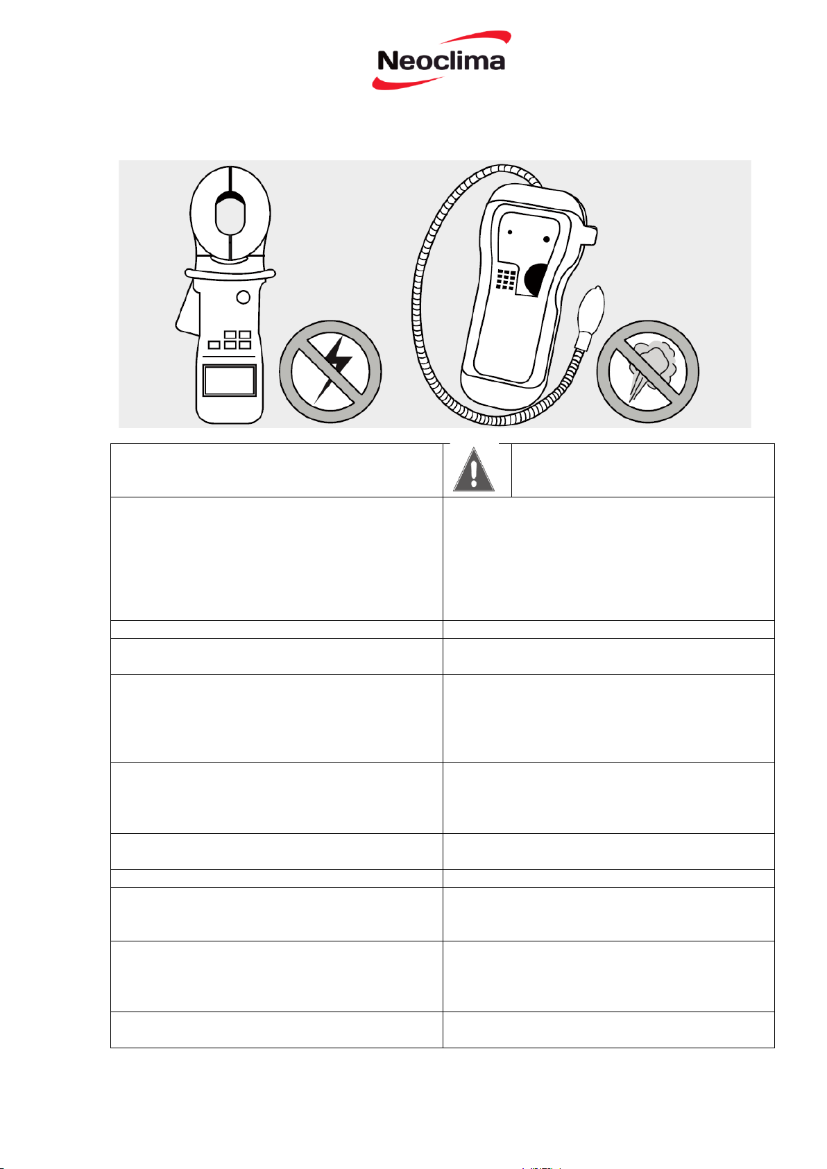
Перевірки безпеки електричної системи
ЗАСТЕРЕЖЕННЯ
Після встановлення переконайтесь у тому, що
електрична проводка зроблена відповідно до
місцевих та національних правил, а також
відповідно до Посібника для встановлення.
РИЗИК УРАЖЕННЯ ЕЛЕКТРИЧНИМ
СТРУМОМ.
ВСЯ ПРОВОДКА ПОВИННА ВІДПОВІДАТИ
МІСЦЕВИМ І НАЦІОНАЛЬНИМ
ЕЛЕКТРОТЕХНІЧНИМ НОРМАМ,
І ПОВИННА БУТИ ВСТАНОВЛЕНА
ЛІЦЕНЗОВАНИМ ЕЛЕКТРИКОМ.
ДО ПОЧАТКУ ПРОБНОЇ ЕКСПЛУАТАЦІЇ
Перевірка витоку газу
Перевірте заземлення
Існує два різних методи перевірити наявність
витоків газу.
Виміряйте опір заземлення за допомогою
візуального виявлення та тестера опору
заземлення. Опір заземлення має бути менше 4.
Метод мильної води
Використовуючи м'яку щітку, нанесіть мильну
воду або рідкий миючий засіб на всі точки
з’єднання труб на внутрішньому і зовнішньому
блоках. Наявність бульбашок вказує на витік.
Примітка: Ця вимога може встановлюватись у
деяких місцевостях в США.
Метод детектора витоку
При використанні детектора витоку зверніться
до Посібника з експлуатації приладу для
отримання інструкцій щодо використання.
ПІД ЧАС ПРОБНОЇ ЕКСПЛУАТАЦІЇ
ПІСЛЯ ВИКОНАННЯ ПЕРЕВІРОК ВИТОКУ
ГАЗУ
Перевірте, чи існує витік струму
Під час пробної експлуатації використовуйте
електронний мультиметр для проведення
повного тесту витоку струму.
Переконавшись у тому, що ВИТІК ВІДСУТНІЙ
у всіх точки з’єднання труб, закрийте кришку
клапана на зовнішньому блоці.
Якщо виявлений витік струму, негайно
вимкніть пристрій і викличте кваліфікованого
електрика, щоб знайти і усунути причину
витоку.
Примітка: Ця вимога може встановлюватись у
деяких місцевостях в США.
Перевірка витоку струму і газу
43

ДО ПОЧАТКУ ПРОБНОЇ ЕКСПЛУАТАЦІЇ
Список
необхідних
перевірок
Задовільно
Незадовільно
Відсутність
витоку струму
Блок
заземлений
належним
чином
Всі електричні
клеми закриті
належним
чином
Внутрішні і
зовнішні блоки
міцно
встановлені
Відсутні
витоки на усіх
точках з'єднань
труб
Вода
належним
чином витікає
з дренажного
шлангу
Всі
трубопроводи
ізольовані
належним
чином
Блок виконує
функцію
COOL
правильно
Блок виконує
функцію HEAT
правильно
Жалюзі
внутрішнього
блоку
обертається
правильно
Внутрішній
блок реагує на
пульт
дистанційного
керування
Пробна експлуатація повинна проводитись
тільки після виконання наступних кроків:
• Перевірка безпеки електричної системи Переконайтеся, що електрична система
пристрою є безпечною і працює належним
чином
• Перевірка витоку газу - Перевірте всі
вальцовачні з'єднання і переконайтеся, що
система не протікає
• Переконайтеся, що газовий і рідинний
клапани (високого і низького тиску) повністю
відкриті
Вказівки для пробної експлуатації
Пробна експлуатація повинні тривати
принаймні 30 хвилин.
1. Підключіть живлення до пристрою.
2. Натисніть кнопку ON/OFF на пульті
дистанційного керування, щоб увімкнути його.
3. Натисніть кнопку MODE, щоб полистати по
черзі наступні функції:
• COOL – Виберіть мінімально можливу
температуру
• HEAT – Виберіть найвищу можливу
температуру
4. Дайте кожній функції попрацювати протягом
5 хвилин і виконайте наступні перевірки:
ПРОБНА ЕКСПЛУАТАЦІЯ
44

ПОДВІЙНА ПЕРЕВІРКА ТРУБНИХ
З'ЄДНАНЬ
Під час експлуатації тиск контуру
холодоагенту буде збільшуватися. Це може
спричинити витік, який не був встановлений
під час первинної перевірки на герметичність.
Знайдіть час протягом пробної експлуатації,
щоб двічі перевірити всі точки з’єднання труб
холодоагенту на наявність витоків. Див. розділ
«Перевірка витоку газу» для отримання
вказівок.
5. Після успішного завершення пробної
експлуатації, і ви упевнені, що всі пункти із
списку перевірки показали задовільний
результат, виконаєте наступні дії:
а. За допомогою пульта дистанційного
керування поверніть блок до нормальної
робочої температури.
б. Використовуючи ізоляційну стрічку,
оберніть точки з'єднань труб холодоагенту
внутрішнього блоку, що залишились не
оберненими протягом встановлення
внутрішнього блоку.
ЯКЩО КІМНАТНА ТЕМПЕРАТУРА НИЖЧЕ
17°С (63°F)
Ви не можете використовувати пульт
дистанційного керування, щоб увімкнути
функцію COOL, коли кімнатна температура
нижче 17°С. У цьому випадку, ви можете
використовувати кнопку ручного управління
для перевірки функцію COOL.
1. Знайдіть кнопку ручного управління на
правій бічній панелі приладу. Див. Рис. 8.1.
2. Натисніть кнопку MANUAL CONTROL
один раз, щоб активувати режим FORCED
AUTO.
3. Натисніть кнопку MANUAL CONTROL ще
раз для активації режиму FORCED COOLING.
4. Виконайте пробний пуск у звичайному
порядку
Кнопка ручного
керування
Рис. 8.1
45

ІНФОРМАЦІЯ ПРО ПІДТВЕРДЖЕННЯ ВІДПОВІДНОСТІ ПРОДУКТУ
Кондиціонери відповідають вимогам Технічного Регламенту електромагнітної
сумісності обладнання (затвердженому постановою Кабінету Міністрів України від
16 грудня 2015р. № 1077), вимогам Технічного Регламенту низьковольтного електричного
обладнання (затвердженому постановою Кабінету Міністрів України від 16 грудня 2015р.
№1067), вимогам Технічного Регламенту обмеження використання деяких небезпечних
речовин в електричному та електронному обладнанні (затвердженому постановою
Кабінету Міністрів України від 10 березня 2017р. № 139), та вимогам Технічного
Регламенту енергетичного маркування кондиціонерів повітря (затвердженому
постановою Кабінету Міністрів України від 24 травня 2017р. № 360).
Декларації про відповідність можна знайти на сайті www.optіm.ua у розділі «Підтримка»
Адреса потужностей виробництва:
«ГД МІДЕЯ» Індустріал Сіті, Бейжао Шунде 528 311 Фошань Гуандонг, Китайська
Народна Республіка
Уповноважений Представник в Україні
ТОВ «ТОРГОВА КОМПАНІЯ «ОПТІМ» Україна, 03134 м. Київ, вул. Пшенична, 9
тел.: (044) 406-40-46
факс: (044) 406-40-45
Тел. гарячої лінії: 0-800-50-70-35 (безкоштовно зі стаціонарних телефонів, в межах
України).
Увага! У зв'язку з тим, що перелік сервісних центрів постійно змінюється,
Ви
на
актуальний перелік авторизованих сервісних центрів Ви можете отримати на
офіційному сайті: http://optim911.com.ua
www.optim.ua
Будь-яку додаткову
Термін
До
введення
виробництва
Дата
в
служби
- 5
експлуатацію
інформацію про сервіс
років
.
на
термін зберігання
вказана
виробі
.
можете
отримати
необмежений.
сайті
46
SPLIT-TYPE ROOM AIR CONDITIONER
Owner’s Manual &
Installation Manual
IMPORTANT NOTE:
Read this manual carefully before installing
or operating your new air conditioning
unit. Make sure to save this manual for
future reference.
Please check the applicable models, technical
data, F-GAS(if any) and manufacturer information
from the “Owner's Manual - Product Fiche ”
in the packaging of the outdoor unit.
(European Union products only)

Table of Contents
Safety Precautions
...............................................................................03
Owner’s Manual
Unit Specifications and Features
1. Indoor unit display.........................................................................................................................07
2. Operating temperature..................................................................................................................09
3. Other features ..............................................................................................................................10
4. Setting angle of airflow.................................................................................................................11
5. Manual operation (without Remote)..............................................................................................11
Care and Maintenance
......................................................................12
Troubleshooting.................................................................................14
...........................................................07

Installation Manual
Accessories
..........................................................................................17
Installation Summary - Indoor Unit .................................................18
Unit Parts
Indoor Unit Installation
1. Select installation location..............................................................................................................20
2. Attach mounting plate to wall........................................................................................................20
3. Drill wall hole for connective piping................................................................................................21
4. Prepare refrigerant piping...............................................................................................................22
5. Connect drain hose........................................................................................................................22
6. Connect signal cable......................................................................................................................23
7. Wrap piping and cables.................................................................................................................24
8. Mount indoor unit.........................................................................................................................25
Outdoor Unit Installation.........................................................................26
1. Select installation location..............................................................................................................26
2. Install drain joint............................................................................................................................27
3. Anchor outdoor unit......................................................................................................................27
4. Connect signal and power cables...................................................................................................29
.............................................................................................19
......................................................................20
Refrigerant Piping Connection........................................................30
A. Note on Pipe Length....................................................................................................................30
B.
Connection Instructions –Refrigerant Piping.................................................................................30
1. Cut pipe.................................................................................................................................30
2. Remove burrs.........................................................................................................................31
3. Flare pipe ends.......................................................................................................................31
4. Connect pipes........................................................................................................................31
Air Evacuation...................................................................................33
1. Evacuation Instructions.................................................................................................................33
2. Note on Adding Refrigerant.........................................................................................................34
Electrical and Gas Leak Checks........................................................35
Test Run.............................................................................................36
Safety
Safety Precautions
Read Safety Precautions Before Operation and Installation
Incorrect installation due to ignoring instructions can cause serious damage or injury.
The seriousness of potential damage or injuries is classified as either a WARNING or CAUTION.
Safety
Precautions
WARNING
This symbol indicates the possibility
of personnel injury or loss of life.
This symbol indicates the possibility of
property damage or serious consequences.
CAUTION
WARNING
This appliance can be used by children aged from 8 years and above and persons with reduced
physical, sensory or mental capabilities or lack of experience and knowledge if they have been given
supervision or instruction concerning use of the appliance in a safe way and understand the hazards
involved. Children shall not play with the appliance. Cleaning and user maintenance shall not be
made by children without supervision(EN Standard requirements).
This appliance is not intended for use by persons(including children) with reduced physical, sensory
or mental capabilities, or lack of experience and knowledge, unless they have been given supervision
or instruction concerning use of the appliance by a person responsible for their safety. Children
should be supervised to ensure that they do not play with the appliance(IEC Standard requirements).
WARNINGS FOR PRODUCT USE
•
If an abnormal situation arises (like a burning smell), immediately turn off the unit and disconnect
the power. Call your dealer for instructions to avoid electric shock, fire or injury.
•
Do not
insert fingers, rods or other objects into the air inlet or outlet. This may cause injury, since
the fan may be rotating at high speeds.
•
Do not
use flammable sprays such as hair spray, lacquer or paint near the unit. This may cause
fire or combustion.
Do not
•
operate the air conditioner in places near or around combustible gases. Emitted gas may
collect around the unit and cause explosion.
Do not
•
operate your air conditioner in a wet room such as a bathroom or laundry room. Too
much exposure to water can cause electrical components to short circuit.
•
•
Do not
Do not
expose your body directly to cool air for a prolonged period of time.
allow children to play with the air conditioner. Children must be supervised around the
unit at all times.
•
If the air conditioner is used together with burners or other heating devices, thoroughly ventilate
the room to avoid oxygen deficiency.
•
In certain functional environments, such as kitchens, server rooms, etc., the use of specially
designed air-conditioning units is highly recommended.
Page 3

Safety
Precautions
CLEANING AND MAINTENANCE WARNINGS
•
Turn off the device and disconnect the power before cleaning. Failure to do so can cause
electrical shock.
•
•
Do not
Do not
clean the air conditioner with excessive amounts of water.
clean the air conditioner with combustible cleaning agents. Combustible cleaning agents
can cause fire or deformation.
CAUTION
•
Turn off the air conditioner and disconnect the power if you are not going to use it for a long time.
•
Turn off and unplug the unit during storms.
•
Make sure that water condensation can drain unhindered from the unit.
• Do not
• Do not
• Do not
• Do not
operate the air conditioner with wet hands. This may cause electric shock.
use device for any other purpose than its intended use.
climb onto or place objects on top of the outdoor unit.
allow the air conditioner to operate for long periods of time with doors or windows open,
or if the humidity is very high.
ELECTRICAL WARNINGS
•
Only use the specified power cord. If the power cord is damaged, it must be replaced by the
manufacturer
•
Keep power plug clean. Remove any dust or grime that accumulates on or around the plug. Dirty
, its service agent or similarly qualified persons in order to avoid a hazard.
plugs can cause fire or electric shock.
•
Do not
pull power cord to unplug unit. Hold the plug firmly and pull it from the outlet. Pulling
directly on the cord can damage it, which can lead to fire or electric shock.
•
•
Do not
Do not
modify the length of the power supply cord or use an extension cord to power the unit.
share the electrical outlet with other appliances. Improper or insufficient power supply
can cause fire or electrical shock.
The product must be properly grounded at the time of installation, or electrical shock may occur.
•
For all electrical work, follow all local and national wiring standards, regulations, and the
•
Installation Manual. Connect cables tightly, and clamp them securely to prevent external forces
from damaging the terminal. Improper electrical connections can overheat and cause fire, and may
also cause shock.
All electrical connections must be made according to the Electrical Connection
Diagram located on the panels of the indoor and outdoor units.
•
All wiring must be properly arranged to ensure that the control board cover can close properly. If
the control board cover is not closed properly, it can lead to corrosion and cause the connection
points on the terminal to heat up, catch fire, or cause electrical shock.
•
If connecting power to fixed wiring, an all-pole disconnection device which has at least 3mm
clearances in all poles, and have a leakage current that may exceed 10mA, the residual current
device(RCD) having a rated residual operating current not exceeding 30mA, and disconnection
must be incorporated in the fixed wiring in accordance with the wiring rules.
TAKE NOTE OF FUSE SPECIFICATIONS
The air conditioner’s circuit board (PCB) is designed with a fuse to provide overcurrent protection.
The specifications of the fuse are printed on the circuit board ,such as :
Indoor unit: T3.15AL/250VAC, T5AL/250VAC, T3.15A/250VAC, T5A/250VAC, etc.
Outdoor unit: T20A/250VAC(<=18000Btu/h units), T30A/250VAC(>18000Btu/h units)
NOTE: For the units with R32 or R290 refrigerant , only the blast-proof ceramic fuse can be used.
Page 4
WARNINGS FOR PRODUCT INSTALLATION
1.
Installation must be performed by an authorized dealer or specialist. Defective installation can
cause water leakage, electrical shock, or fire.
2.
Installation must be performed according to the installation instructions. Improper installation
can cause water leakage, electrical shock, or fire.
(In North America,installation must be performed in accordance with the requirement of NEC
and CEC by authorized personnel only.)
Contact an authorized service technician for repair or maintenance of this unit. This appliance
3.
shall be installed in accordance with national wiring regulations.
Only use the included accessories, parts, and specified parts for installation. Using non-standard
4.
parts can cause water leakage, electrical shock, fire, and can cause the unit to fail.
5.
Install the unit in a firm location that can support the unit’s weight. If the chosen location cannot
support the unit’s weight, or the installation is not done properly, the unit may drop and cause
serious injury and damage.
Install drainage piping according to the instructions in this manual. Improper drainage may
6.
cause water damage to your home and property.
7.
For units that have an auxiliary electric heater, do not install the unit within 1 meter (3 feet) of
any combustible materials.
8.
Do not
combustible
install the unit in a location that may be exposed to combustible gas leaks. If
gas accumulates around the unit, it may cause fire.
Safety
Precautions
9.
Do not turn on the power until all work has been completed.
When moving or relocating the air conditioner, consult experienced service technicians for
10.
disconnection and reinstallation of the unit.
11.
How to install the appliance to its support, please read the information for details in "indoor unit
installation" and "outdoor unit installation" sections .
Note about Fluorinated Gasses(Not applicable to the unit using R290 Refrigerant)
1.
This air-conditioning unit contains fluorinated greenhouse gasses. For specific information on the
type of gas and the amount, please refer to the relevant label on the unit itself or
“Owner's Manual - Product Fiche ” in the packaging of the outdoor unit.
Union products only)
2.
Installation, service, maintenance and repair of this unit must be performed by a certified
.
the
(European
technician.
3.
Product uninstallation and recycling must be performed by a certified technician.
4.
For equipment that contains fluorinated greenhouse gases in quantities of 5 tonnes of CO2
2
equivalent or more, but of less than 50 tonnes of CO
detection system installed, it must be checked for leaks at least every 24 months.
5.
When the unit is checked for leaks, proper record-keeping of all checks is strongly recommended.
equivalent, If the system has a leak-
Page 5

Safety
Precautions
WARNING for Using R32/R290 Refrigerant
When flammable refrigerant are employed, appliance shall be stored in a well -ventilated area
where the room size corresponds to the room area as specifiec for operation.
For R32 frigerant models:
Appliance shall be installed, operated and stored in a room with a floor area larger than 4m .
Appliance shall not be installed in an unvertilated space, if that space is smaller than 4m .
For R290 refrigerant models, the minimum room size needed:
<=9000Btu/h units: 13m
>9000Btu/h and <=12000Btu/h units: 17m
>12000Btu/h and <=18000Btu/h units: 26m
>18000Btu/h and <=24000Btu/h units: 35m
2
2
2
2
Reusable mechanical connectors and flared joints are not allowed indoors.
(EN Standard Requirements).
Mechanical connectors used indoors shall have a rate of not more than 3g/year at 25%
of the maximum allowable pressure. When mechanical connectors are reused indoors,
sealing parts shall be renewed. When flared joints are reused indoors, the flare part
shall be re-fabricated. (UL Standard Requirements)
When mechanical connectors are reused indoors, sealing parts shall be renewed. When
flared joints are reused indoors, the flare part shall be re-fabricated.
(IEC Standard Requirements)
2
2
European Disposal Guidelines
This marking shown on the product or its literature, indicates that waste electrical and
eletrical equipment should not be mixed with general household waste.
Correct Disposal o f T h is Product
(Waste Electrical & Electronic Equipment)
This appliance contains refrigerant and other potentially hazardous materials. When disposing of
this appliance, the law requires special collection and treatment. Do not dispose of this product as
household waste or unsorted municipal waste.
When disposing of this appliance, you have the following options:
• Dispose of the appliance at designated municipal electronic waste collection facility.
• When buying a new appliance, the retailer will take back the old appliance free of charge.
• The manufacturer will take back the old appliance free of charge.
• Sell the appliance to certified scrap metal dealers.
Special notice
Disposing of this appliance in the forest or other natural surroundings endangers your health and is
bad for the environment. Hazardous substances may leak into the ground water and enter the food
chain.
Page 6

Unit Specifications and Features
Specifications
Indoor unit display
NOTE: Different models have different front panel and display window. Not all the indicators
describing below are available for the air conditioner you purchased. Please check the indoor display
window of the unit you purchased.
Illustrations in this manual are for explanatory purposes. The actual shape of your indoor unit
may be slightly different. The actual shape shall prevail.
and Features
Unit
Front Panel
Louver
Functional Filter
(On Back of Main Filter - Some Units)
Display window
(A)
“ ”
“ ”
“ ” when Wireless Control feature is activated(some units)
when ECO function is activated(some units)
Lights up in different colour according to the operation
mode(some units):
Under COOL and DRY mode, it displays as cool colour.
Under HEAT mode, it displays as warm colour.
(B)
Power Cable (Some Units
Remote Control
(C)
)
Remote Control
Holder (Some Units)
(D)
Display Code
Meanings
“ ”
“ ” for 3 seconds when:
• TIMER ON is set
• FRESH , SWING, TURBO , SILENCE or SOLAR PV ECO feature is turned on
“ ” for 3 seconds when:
• TIMER OFF is set
• FRESH , SWING, TURBO , SILENCE or SOLAR PV ECO feature is turned off
“ ” when anti-cold air feature is turned on
“ ” when defrosting(cooling & heating units)
“ ” when unit is self-cleaning
“ ” when 8 C heating feature is turned on
Displays temperature, operation feature and Error codes:
Page 7
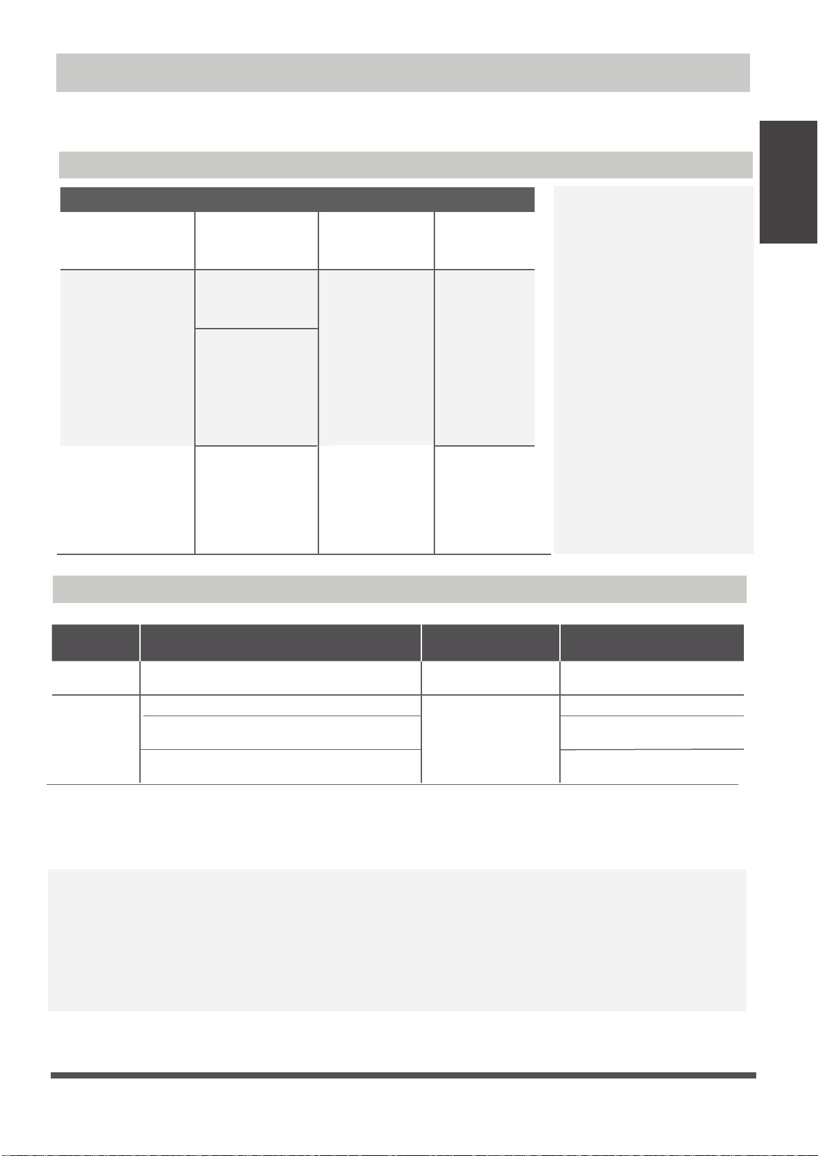
Operating temperature
When your air conditioner is used outside of the following temperature ranges, certain safety
protection features may activate and cause the unit to disable.
Inverter Split Type
Specifications
and Features
Unit
COOL mode HEAT mode DRY mode
Room Temperature
Outdoor
Temperature
17°C - 32°C
(62°F - 90°F)
0°C - 50°C
(32°F - 122°F)
-15°C - 50°C
(5°F - 122°F)
(For models with
low temp. cooling
systems.)
0°C - 52°C
(32°F - 126°F)
(For special
tropical models)
Fixed-speed Type
0°C - 30°C
(32°F - 86°F)
-15°C - 24°C
(5°F - 75°F)
10°C - 32°C
(50°F - 90°F)
0°C - 50°C
(32°F - 122°F)
0°C - 52°C
(32°F - 126°F)
(For special
tropical models)
FOR OUTDOOR UNITS
WITH AUXILIARY
ELECTRIC HEATER
When outside
temperature is below 0°C
(32°F ), we strongly
recommend keeping the
unit plugged in at all
time to ensure smooth
ongoing performance.
Room
Temperature
Outdoor
Temperature
COOL mode
17°C-32°C (62°F-90°F)
18°C-43°C (64°F-109°F)
(For models with low-temp cooling systems)
-7°C-43°C (19°F-109°F)
18°C-52°C (64°F-126°F)
(For special tropical models)
HEAT mode
0°C-30°C
(32°F-86°F)
-7°C-24°C
(19°F-75°F)
DRY mode
10°C-32°C (50°F-90°F)
11°C-43°C (52°F-109°F)
18°C-43°C (64°F-109°F)
18°C-52°C (64°F-126°F)
(For special tropical models)
NOTE: Room relative humidity less than 80%. If the air conditioner operates in excess of this
figure, the surface of the air conditioner may attract condensation. Please sets the vertical air
flow louver to its maximum angle (vertically to the floor), and set HIGH fan mode.
To further optimize the performance of your unit, do the following:
• Keep doors and windows closed.
• Limit energy usage by using TIMER ON and TIMER OFF functions.
• Do not block air inlets or outlets.
• Regularly inspect and clean air filters.
Page 9
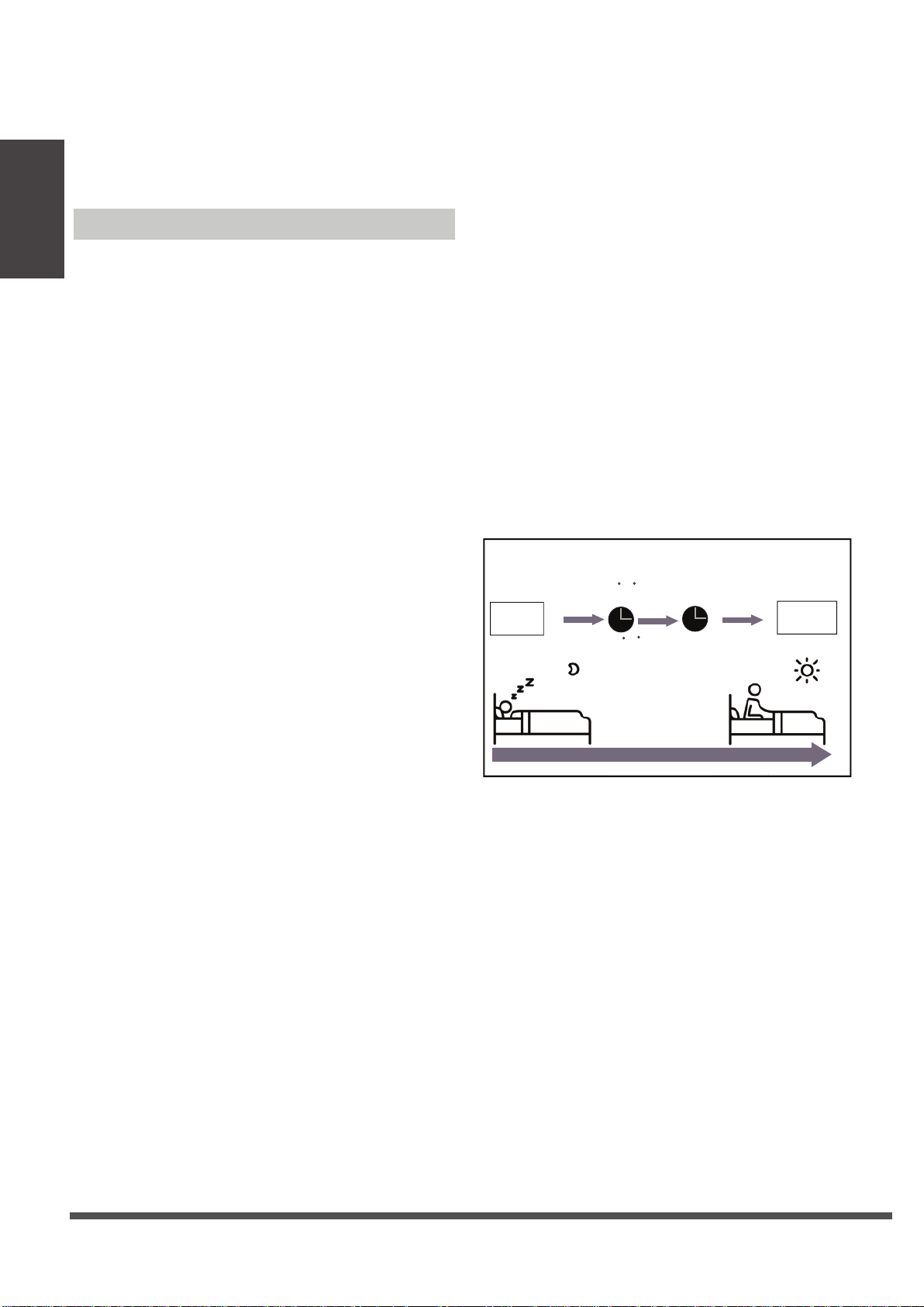
A guide on using the infrared remote is not
included in this literature package.
the functions are available for the air
Specifications
and Features
conditioner, please check the indoor display
and remote control of the unit you purchased.
Unit
Other Features
• Auto-Restart(some units)
• Anti-mildew (some units)
• Wireless Control (some units)
• Louver Angle Memory(some units)
Not all
If the unit loses power, it will automatically
restart with the prior settings once power has
been restored.
When turning off the unit from COOL, AUTO
(COOL), or DRY modes, the air conditioner will
continue operate at very low power to dry up
condensed water and prevent mildew growth.
Wireless control allows you to control your air
conditioner using your mobile phone and a
wireless connection.
For the USB device access, replacement,
maintenance operations must be carried
out by professional staff.
When turning on your unit, the louver will
automatically resume its former angle.
Sleep Operation
•
The SLEEP function is used to decrease
energy use while you sleep (and don’t
need the same temperature settings to
stay comfortable). This function can only
be activated via remote control. And the
Sleep function is not available in FAN or
DRY mode.
Press the SLEEP button when you are
ready to go to sleep. When in COOL mode,
the unit will increase the temperature
by 1°C (2°F) after 1 hour, and will increase
an additional 1°C (2°F) after another hour.
When in HEAT mode, the unit will decrease
the temperature by 1°C (2°F) after 1 hour,
and will decrease an additional 1°C (2°F)
after another hour.
The sleep feature will stop after 8 hours and
the system will keep running with final
situation.
SLEEP Operation
Cool mode(+1 C/2 F) per hour
Set
temperature
for the first two hours
1hr
Heat mode( -1 C/2 F) per hour
for the first two hours
1hr
Keep
running
• Refrigerant Leakage Detection
(some units)
The indoor unit will automatically display “EC”
or “EL0C”or flash LEDS (model dependent )
when it detects refrigerant leakage.
Saving energy during sleep
Page 10

•
Setting Angle of Air Flow
Setting vertical angle of air flow
While the unit is on, use the SWING/DIRECT
button on remote control to set the direction
(vertical angle) of airflow. Please refer to the
Remote Control Manual for details.
NOTE ON LOUVER ANGLES
When using COOL or DRY mode, do not set
louver at too vertical an angle for long periods
of time. This can cause water to condense on
the louver blade, which will drop on your floor
or furnishings.
When using COOL or HEAT mode, setting the
louver at too vertical an angle can reduce the
performance of the unit due to restricted air
flow.
Setting horizontal angle of air flow
The horizontal angle of the airflow must be set
manually. Grip the deflector rod (See Fig.B)
and manually adjust it to your preferred direction.
For some units, the horizontal angle of the airflow
can be set by remote control. please refer to the
Remote Control Manual.
and Features
Range
NOTE: Do not move louver by hand. This will
cause the louver to become out of sync. If this
occurs, turn off the unit and unplug it for a few
seconds, then restart the unit. This will reset the
louver.
Fig. A
CAUTION
Do not put your fingers in or near the blower
and suction side of the unit. The high-speed
fan inside the unit may cause injury.
Specifications
Unit
Manual Operation(without remote)
CAUTION
The manual button is intended for testing purposes
and emergency operation only. Please do not use this
function unless the remote control is lost and it is
absolutely necessary. To restore regular operation,
use the remote control to activate the unit. Unit must
be turned off before manual operation.
To operate your unit manually:
Open the front panel of the indoor unit.
1.
Locate the
2.
the right-hand side of the unit.
Press the MANUAL CONTROL button one
3.
time to activate FORCED AUTO mode.
Press the MANUAL CONTROL button again
4.
to activate FORCED COOLING mode.
Press the MANUAL CONTROL button a third
5.
time to turn the unit off.
Close the front panel.
6.
MANUAL CONTROL button on
Deflector
rod
Fig. B
Manual control button
Page 11
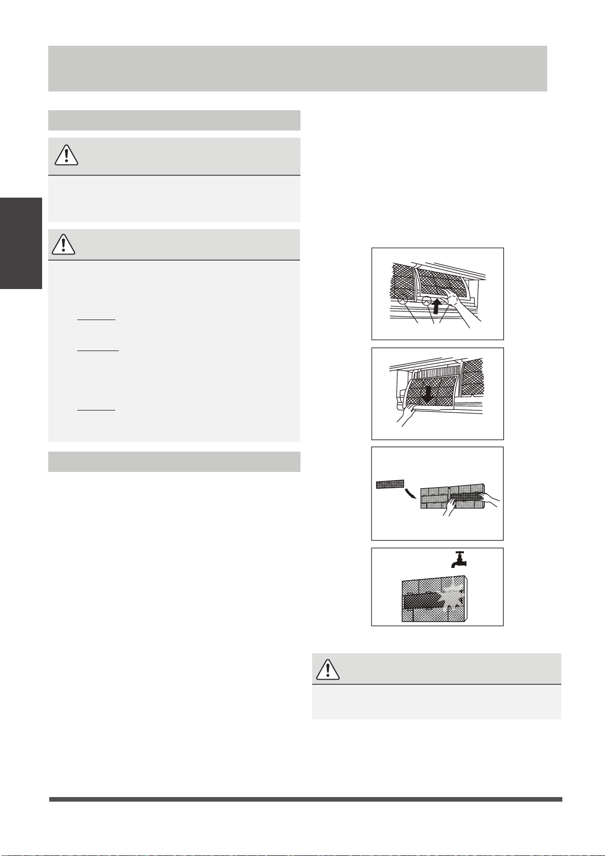
Care and Maintenance
Cleaning Your Indoor Unit
6.
Rinse the filter with fresh water, then shake
off excess water.
ALWAYS TURN OFF YOUR AIR CONDITIONER
SYSTEM AND DISCONNECT ITS POWER SUPPLY
Maintenance
BEFORE CLEANING OR MAINTENANCE.
Care and
Only use a soft, dry cloth to wipe the unit clean.
If the unit is especially dirty, you can use a cloth
soaked in warm water to wipe it clean.
•
•
•
BEFORE CLEANING OR
MAINTENANCE
CAUTION
Do not use chemicals or chemically treated
cloths to clean the unit
Do not use benzene, paint thinner,
polishing powder or other solvents to clean
the unit. They can cause the plastic surface
to crack or deform.
Do not use water hotter than 40°C (104°F)
to clean the front panel. This can cause the
panel to deform or become discolored.
7.
Dry it in a cool, dry place, and refrain from
exposing it to direct sunlight.
8.
When dry, re-clip the air freshening filter to
the larger filter, then slide it back into the
indoor unit.
9.
Close the front panel of the indoor unit.
Filter Tabs
Cleaning Your Air Filter
A clogged air conditioner can reduce the cooling
efficiency of your unit, and can also be bad for
your health. Make sure to clean the filter once
every two weeks.
1. Lift the front panel of the indoor unit.
2. Grip the tab on the end of the filter, lift it
up,then
3. Now pull the filter out.
4. If your filter has a small air freshening filter,
unclip it from the larger filter. Clean this air
freshening filter with a hand-held vacuum.
5. Clean the large air filter with warm, soapy
water. Be sure to use a mild detergent.
pull it towards yourself.
Remove air freshening filter from back of
larger filter (some units)
CAUTION
Do not touch air freshening (Plasma) filter for
at least 10 minutes after turning off the unit.
Page 12
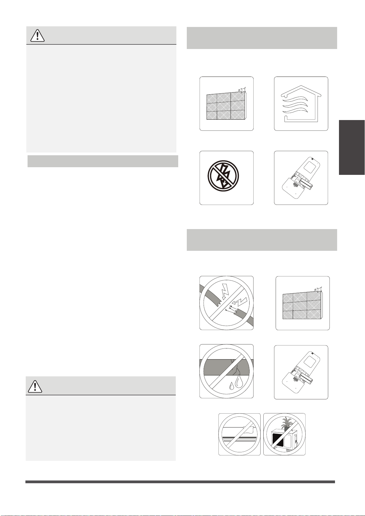
CAUTION
•
Before changing the filter or cleaning,
turn off the unit and disconnect its power
supply.
•
When removing filter, do not touch metal
parts in the unit. The sharp metal edges can
cut you.
•
Do not use water to clean the inside of the
indoor unit. This can destroy insulation and
cause electrical shock.
•
Do not expose filter to direct sunlight when
drying. This can shrink the filter.
Air Filter Reminders (Optional)
Air Filter Cleaning Reminder
After 240 hours of use, the display window on
the indoor unit will flash “CL.” This is a reminder
to clean your filter. After 15 seconds, the unit will
revert to its previous display.
Maintenance –
Long Periods of Non-Use
If you plan not to use your air conditioner for an
extended period of time, do the following:
Clean all filters
Turn off the unit and
disconnect the power
Remove batteries
Turn on FAN function until
unit dries out completely
from remote control
Maintenance
Care and
To reset the reminder, press the LED button
on your remote control 4 times, or press the
MANUAL CONTROL button 3 times. If you don’t
reset the reminder, the “CL” indicator will flash
again when you restart the unit.
Air Filter Replacement Reminder
After 2,880 hours of use, the display window on
the indoor unit will flash “nF.” This is a reminder
to replace your filter. After 15 seconds, the unit
will revert to its previous display.
To reset the reminder, press the LED button
on your remote control 4 times, or press the
MANUAL CONTROL button 3 times. If you don’t
reset the reminder, the “nF” indicator will flash
again when you restart the unit.
CAUTION
•
Any maintenance and cleaning of outdoor
unit should be performed by an authorized
dealer or a licensed service provider.
Maintenance –
Pre-Season Inspection
After long periods of non-use, or before periods
of frequent use, do the following:
Check for damaged wires Clean all filters
Check for leaks Replace batteries
•
Any unit repairs should be performed
by an authorized dealer or a licensed
service provider.
Make sure nothing is blocking all air inlets and outlets
Page 13

If ANY of the following conditions occurs, turn off your unit immediately!
• The power cord is damaged or abnormally warm
• You smell a burning odor
• The unit emits loud or abnormal sounds
• A power fuse blows or the circuit breaker frequently trips
• Water or other objects fall into or out of the unit
DO NOT ATTEMPT TO FIX THESE YOURSELF! CONTACT AN AUTHORIZED
SERVICE PROVIDER IMMEDIATELY!
Troubleshooting
Common Issues
The following problems are not a malfunction and in most situations will not require repairs.
Issue Possible Causes
Troubleshooting
SAFETY PRECAUTIONS
Unit does not turn
on when pressing
ON/OFF button
The unit changes from
COOL/HEAT mode to
FAN mode
The indoor unit
emits white mist
Both the indoor and
outdoor units emit
white mist
The indoor unit makes
noises
Both the indoor unit
and outdoor unit make
noises
The Unit has a 3-minute protection feature that prevents the unit from
overloading. The unit cannot be restarted within three minutes of being
turned off.
The unit may change its setting to prevent frost from forming on the unit.
Once the temperature increases, the unit will start operating in the
previously selected mode again.
The set temperature has been reached, at which point the unit turns off the
compressor. The unit will continue operating when the temperature
fluctuates again.
In humid regions, a large temperature difference between the room’s air
and the conditioned air can cause white mist.
When the unit restarts in HEAT mode after defrosting, white mist may be
emitted due to moisture generated from the defrosting process.
A rushing air sound may occur when the louver resets its position.
A squeaking sound may occur after running the unit in HEAT mode due to
expansion and contraction of the unit’s plastic parts.
Low hissing sound during operation: This is normal and is caused by refrigerant
gas flowing through both indoor and outdoor units.
Low hissing sound when the system starts, has just stopped running, or is
defrosting: This noise is normal and is caused by the refrigerant gas stopping or
changing direction.
Page 14
Squeaking sound: Normal expansion and contraction of plastic and metal parts
caused by temperature changes during operation can cause squeaking noises.
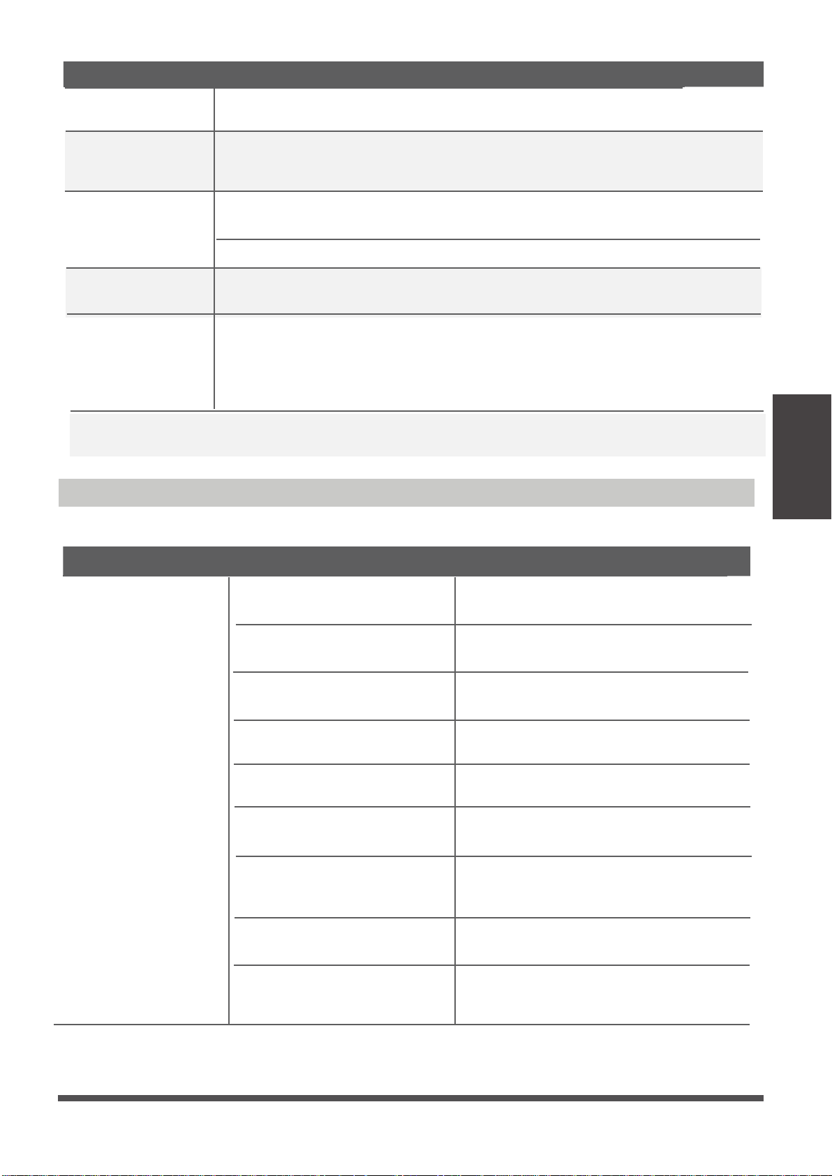
Issue Possible Causes
The outdoor unit
makes noises
Dust is emitted from
either the indoor or
outdoor unit
The unit emits a
bad odor
The fan of the outdoor
unit does not operate
Operation is erratic,
unpredictable, or
unit is unresponsive
NOTE:
If problem persists, contact a local dealer or your nearest customer service center. Provide
them with a detailed description of the unit malfunction as well as your model number.
Troubleshooting
The unit will make different sounds based on its current operating mode.
The unit may accumulate dust during extended periods of non-use, which will be
emitted when the unit is turned on. This can be mitigated by covering the unit during
long periods of inactivity.
The unit may absorb odors from the environment (such as furniture, cooking,
cigarettes, etc.) which will be emitted during operations.
The unit’s filters have become moldy and should be cleaned.
During operation, the fan speed is controlled to optimize product operation.
Interference from cell phone towers and remote boosters may cause the unit to
malfunction.
In this case, try the following:
•
Disconnect the power, then reconnect.
Press ON/OFF button on remote control to restart operation.
•
Troubleshooting
When troubles occur, please check the following points before contacting a repair company.
Problem Possible Causes Solution
Poor Cooling
Performance
Temperature setting may be higher
than ambient room temperature
The heat exchanger on the indoor
or outdoor unit is dirty
The air filter is dirty
The air inlet or outlet of either
unit is blocked
Doors and windows are open
Excessive heat is generated
by sunlight
Too many sources of heat in the
room (people, computers,
electronics, etc.)
Low refrigerant due to leak
or long-term use
Lower the temperature setting
Clean the affected heat exchanger
Remove the filter and clean it according to
instructions
Turn the unit off, remove the obstruction
and turn it back on
Make sure that all doors and windows are
closed while operating the unit
Close windows and curtains during periods
of high heat or bright sunshine
Reduce amount of heat sources
Check for leaks, re-seal if necessary and
top off refrigerant
SILENCE function is activated
(optional function)
SILENCE function can lower product
performance by reducing operating
frequency. Turn off SILENCE function.
Page 15
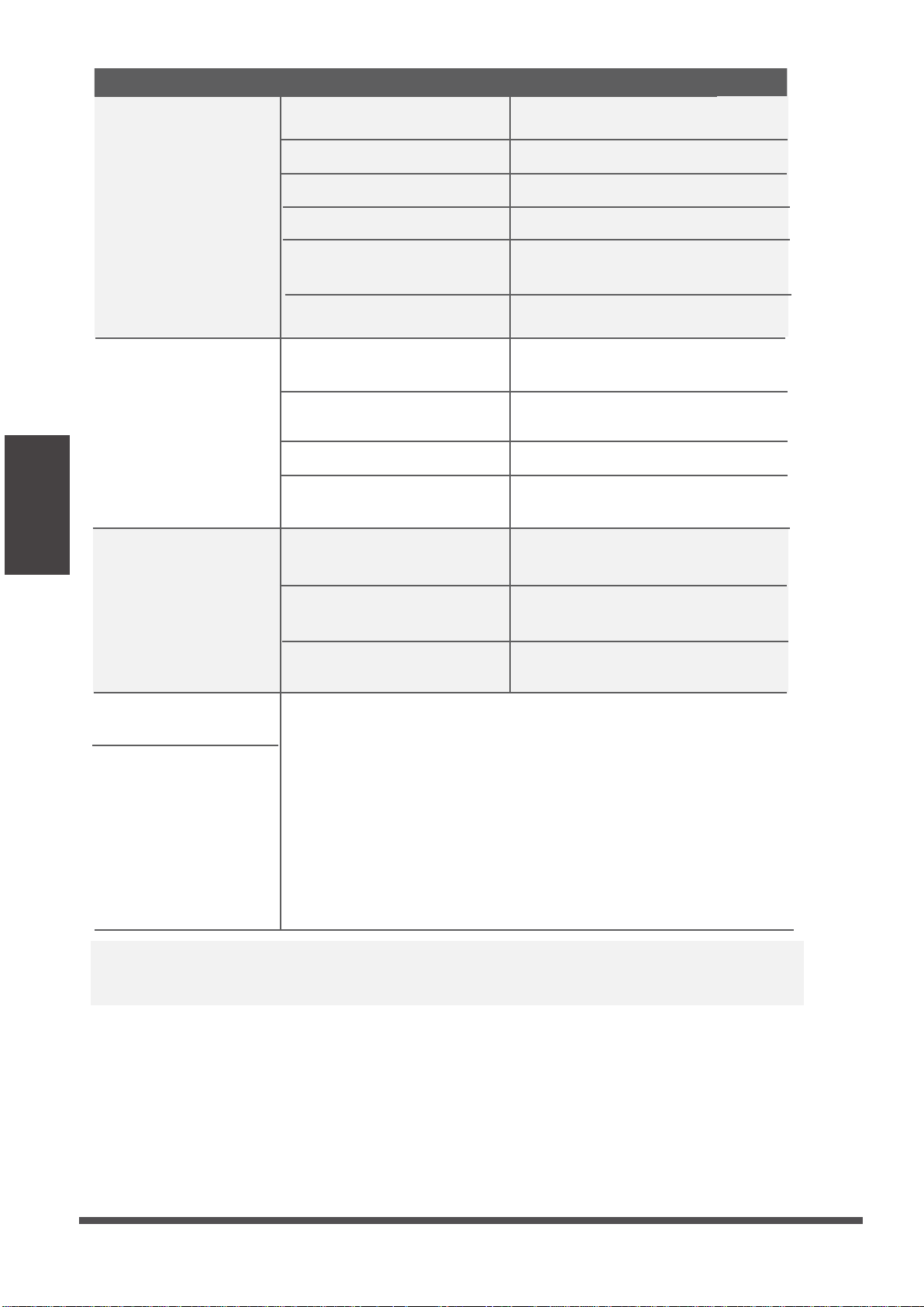
Problem Possible Causes Solution
The unit is not
working
The unit starts and
stops frequently
Troubleshooting
Poor heating
performance
Power failure
The power is turned off Turn on the power
The fuse is burned out
Remote control batteries are dead
The Unit’s 3-minute protection
has been activated
Timer is activated
There’s too much or too little
refrigerant in the system
Incompressible gas or moisture
has entered the system.
The compressor is broken Replace the compressor
The voltage is too high or
too low
The outdoor temperature is
extremely low
Cold air is entering through
doors and windows
Wait for the power to be restored
Replace the fuse
Replace batteries
Wait three minutes after restarting
the unit
Turn timer off
Check for leaks and recharge the
system with refrigerant.
Evacuate and recharge the system
with refrigerant
Install a manostat to regulate the
voltage
Use auxiliary heating device
Make sure that all doors and
windows are closed during use
Indicator lamps
continue flashing
Error code appears and
begins with the letters
as the following in the
window display of
indoor unit:
•
E(x), P(x), F(x)
EH(xx), EL(xx), EC(xx)
•
PH(xx), PL(xx), PC(xx)
•
NOTE:
If your problem persists after performing the checks and diagnostics above,
turn off your unit immediately and contact an authorized service center.
Low refrigerant due to leak or
long-term use
The unit may stop operation or continue to run safely. If the indicator
lamps continue to flash or error codes appear, wait for about 10
minutes. The problem may resolve itself.
If not, disconnect the power, then connect it again. Turn the unit on.
If the problem persists, disconnect the power and contact your nearest
customer service center.
Check for leaks, re-seal if necessary
and top off refrigerant
Page 16
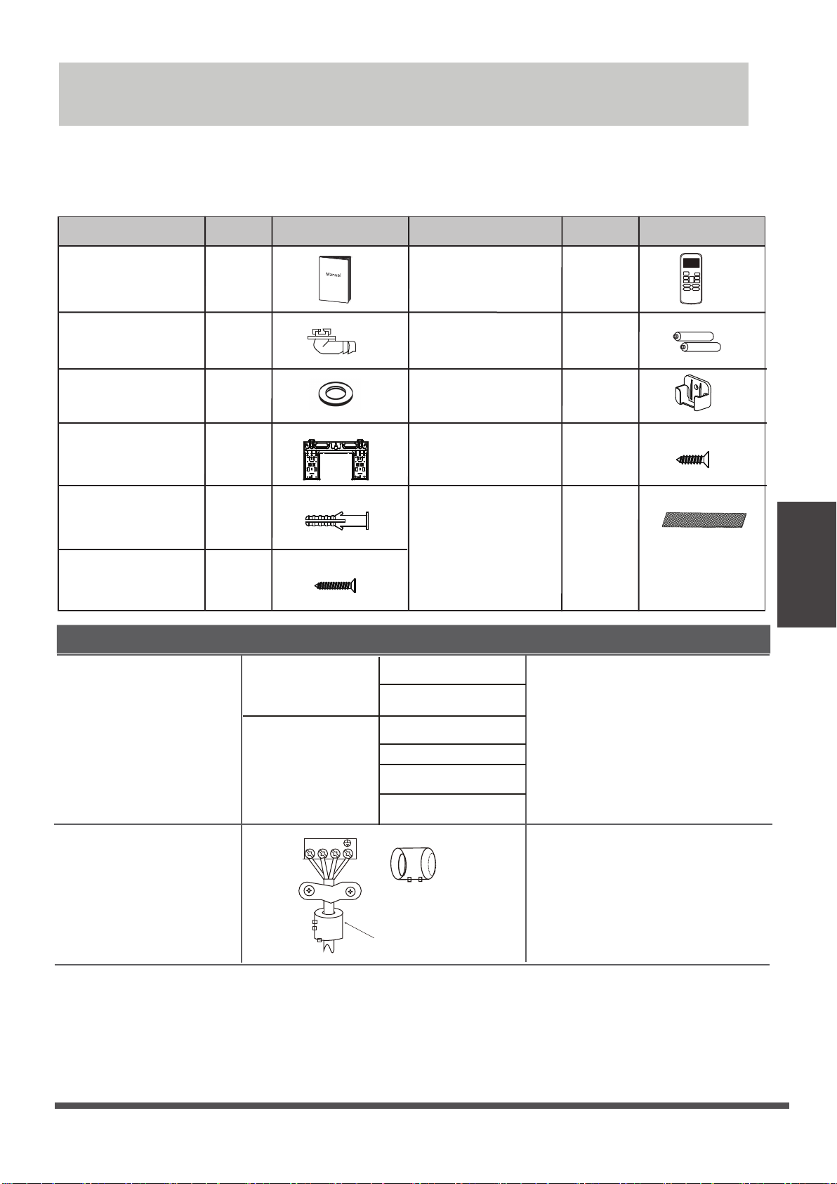
Accessories
The air conditioning system comes with the following accessories. Use all of the installation parts
and accessories to install the air conditioner. Improper installation may result in water leakage,
electrical shock and fire, or cause the equipment to fail. The items are not included
with the air conditioner must be purchased separately.
Name of Accessories Name of AccessoriesQ’ty(pc)
Manual
Drain joint
(for cooling &
heating models)
Seal
(for cooling &
heating models)
Mounting plate
5~8
Anchor
Mounting plate
fixing screw
Name
(depending
on models)
5~8
(depending
on models)
2-3
1
1
1
Shape Q’ty(pc)
Remote controller
Battery
Remote controller
holder(optional)
Fixing screw for
remote controller
holder(optional)
Small Filter
(Need to be installed on
the back of main air filter
by the authorized
technician while installing
the machine)
Shape Quantity(PC)
1
2
1
2
1~2
(depending
on models)
Shape
Accessories
6.35( 1/ 4 i n)
Φ
Liquid side
Φ
9.52( 3/ 8in)
Conn ecting pipe
assembly
Gas side
Φ
9.52( 3/ 8in)
Φ
12. 7( 1/ 2in)
Φ
16( 5 / 8in)
Φ
19( 3/4in)
Parts you must purc hase
separately. Consult the dealer
about the proper pipe size of
the unit you purchased.
Magnetic ring and belt
(if supplied ,please refer to
the wiring diagram to install
it on the connective cable. )
1 2 3
Varies by model
Pass the belt through
the hole of the Magnetic
ring to fix it on the cable
Page 17
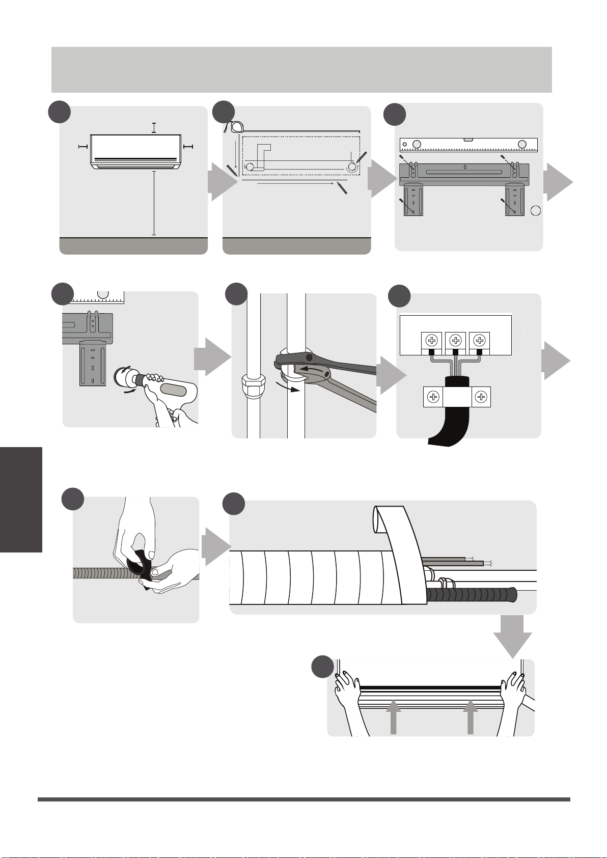
Installation Summary - Indoor Unit
1 2
12cm
(4.75in)
Select Installation Location
4
4
15cm (5.9in)
2.3m (90.55in)
12cm
(4.75in)
Determine Wall Hole Position
5
3
Attach Mounting Plate
6
Installation Summary
-Indoor Unit
Drill Wall Hole
7
Prepare Drain Hose
Connect Piping
Connect Wiring
(not applicable for some
locations in the US )
8
Wrap Piping and Cable
(not applicable for some locations in the US )
9
STEP
8
Page 18
Mount Indoor Unit

Unit Parts
NOTE: The installation must be performed in accordance with the requirement of local and
national standards. The installation may be slightly different in different areas.
1
2
4
5
3
2
6
7
8
4
5
9
11
10
1
Air-break switch
3
6
7
8
11
(1) (2)
Wall Mounting Plate
1
2
Front Panel
Power Cable (Some Units)
3
Louver
4
Functional Filter (On Back of
5
Main Filter - Some Units)
6
Drainage Pipe
7
Signal Cable
8
Refrigerant Piping
Remote Controller
9
Remote controller Holder
10
(Some Units)
Outdoor Unit Power Cable
11
(Some Units)
NOTE ON ILLUSTRATIONS
Illustrations in this manual are for explanatory purposes. The actual shape of your indoor
unit may be slightly different. The actual shape shall prevail.
Page 19
Unit Parts
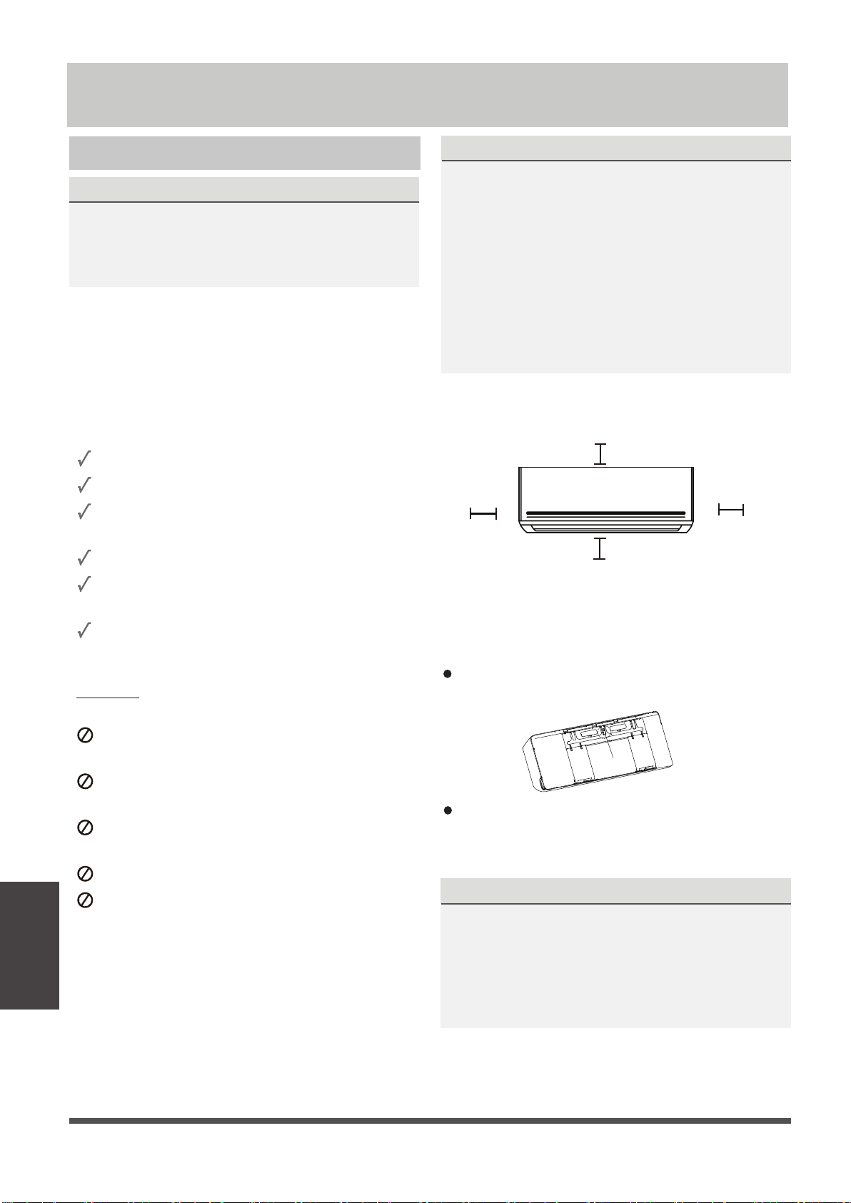
Indoor Unit Installation
Installation Instructions – Indoor unit
PRIOR TO INSTALLATION
Before installing the indoor unit, refer to the
label on the product box to make sure that the
model number of the indoor unit matches the
model number of the outdoor unit.
Step 1: Select installation location
Before installing the indoor unit, you must
choose an appropriate location. The following
are standards that will help you choose an
appropriate location for the unit.
Proper installation locations meet the
following standards:
Good air circulation
Convenient drainage
Noise from the unit will not disturb other
people
Firm and solid—the location will not vibrate
Strong enough to support the weight of the
unit
NOTE ABOUT WALL HOLE:
If there is no fixed refrigerant piping:
While choosing a location, be aware that you
should leave ample room for a wall hole (see
Drill wall hole for connective piping step)
for the signal cable and refrigerant piping
that connect the indoor and outdoor units.
The default position for all piping is the right
side of the indoor unit (while facing the unit).
However, the unit can accommodate piping to
both the left and right.
Refer to the following diagram to ensure
proper distance from walls and ceiling:
15cm (5.9in) or more
12cm (4.75in)
or more
2.3m (90.55in) or more
12cm (4.75in)
or more
Step 2: Attach mounting plate to wall
DO NOT
locations:
Indoor Unit
Installation
A location at least one meter from all other
electrical devices (e.g., TV, radio, computer)
install unit in the following
Near any source of heat, steam, or
combustible gas
Near flammable items such as curtains or
clothing
Near any obstacle that might block air
circulation
Near the doorway
In a location subject to direct sunlight
The mounting plate is the device on which you
will mount the indoor unit.
Remove the screw that attaches the mounting
plate to the back of the indoor unit.
Screw
Secure the mounting plate to the wall with
the screws provided. Make sure that mounting
plate is flat against the wall.
NOTE FOR CONCRETE OR BRICK WALLS:
If the wall is made of brick, concrete, or similar
material, drill 5mm-diameter (0.2in-diameter)
holes in the wall and insert the sleeve anchors
provided. Then secure the mounting plate to
the wall by tightening the screws directly into
the clip anchors.
Page 20
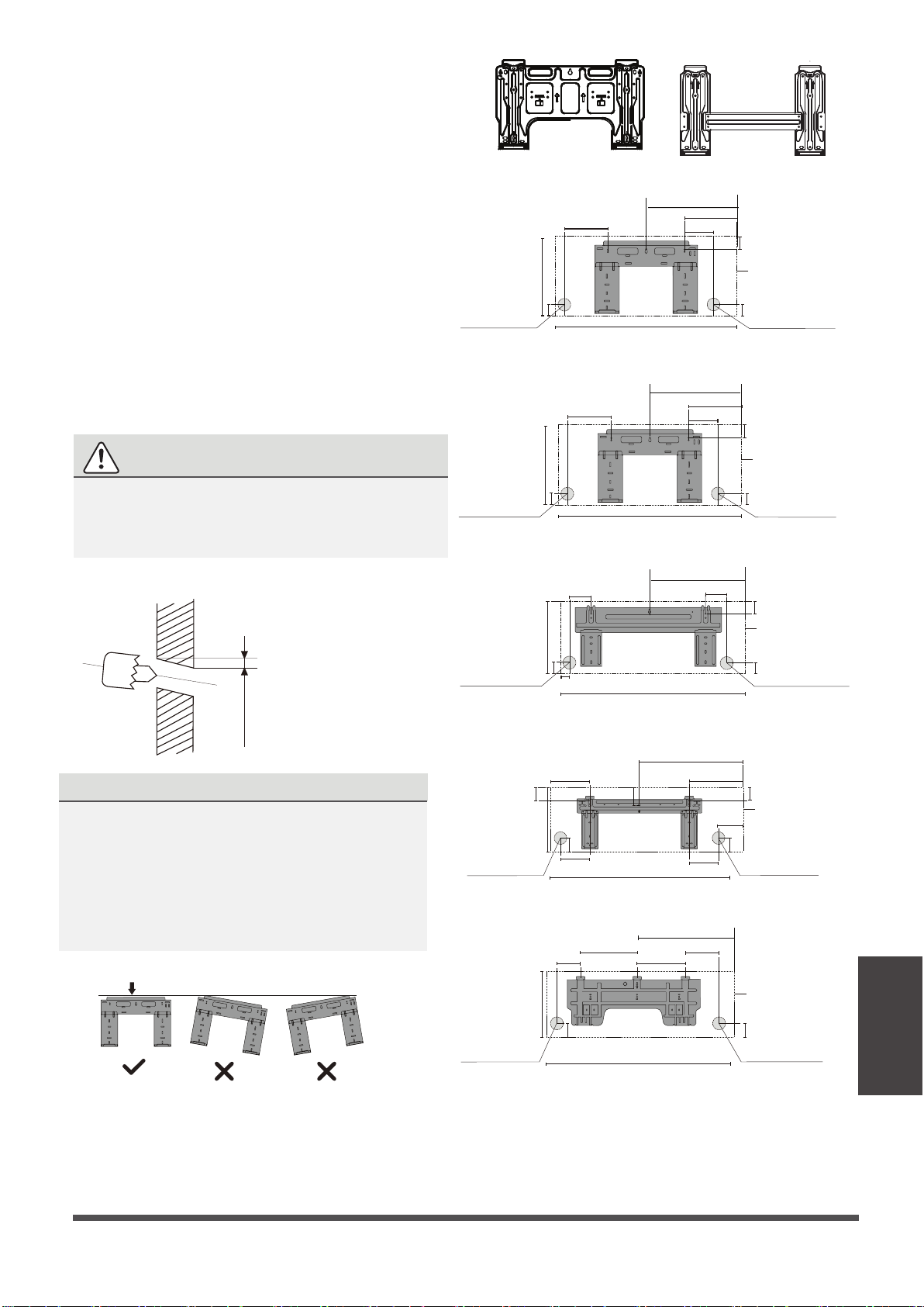
Step 3: Drill wall hole for connective piping
Determine the location of the wall hole based
1.
on the position of the mounting plate. Refer
to Mounting Plate Dimensions.
2. Using a 65mm (2.5in) or 90mm(3.54in)
(depending on models )core drill, drill a
hole in the wall. Make sure that the hole
is drilled at
a slight downward angle, so
that the outdoor end of the hole is lower
than the indoor end by about 5mm to 7mm
(0.2-0.275in). This will ensure proper water
drainage.
3. Place the protective wall cuff in the hole. This
protects the edges of the hole and will help
seal it when you finish the installation process.
CAUTION
When drilling the wall hole, make sure to
avoid wires, plumbing, and other sensitive
components.
Left rear wall
hole 65mm (2.5in)
Left rear wall
hole 65mm (2.5in)
Type A
101mm (4in)
290mm (11.4in)
49mm (1.95in)
192mm (7.55in)
43mm (1.7in)
297mm (11.7in)
722mm (28.45in)
Model A
802mm (31.6in)
Model B
348.4mm (13.7in)
179mm (7.05in)
136mm (5.35in)
426mm (16.8in)
232mm (9.15in)
128mm (5.05in)
Type B
37mm (1.45in)
Indoor unit outline
Right rear wall
49mm (1.95in)
hole 65mm (2.5in)
43mm (1.7in)
Indoor unit outline
Right rear wall
43mm (1.7in)
hole 65mm (2.5in)
Indoor Outdoor
Wall
Left rear wall
mm7-5
(0.2-0.275in)
hole 65mm (2.5in)
MOUNTING PLATE DIMENSIONS
Different models have different mounting plates.
For the different customization requirements, the
shape of the mounting plate may be slightly
Left rear wall
hole 65mm (2.5in)
different. But the installation dimensions are the
same for the same size of indoor unit.
See Type A and Type B for example:
Correct orientation of Mounting Plate
53.5mm
(2.1in)
138mm (5.45in)
57mm (2.25in)
319mm (12.55in)
34mm (1.35in)
219mm (8.6in)
47mm (1.85in)
335mm (13.2in)
174.3mm (6.85in)
389mm (15.3in)
172mm (6.8in)
76mm(3in)
1080mm (42.5in)
Model D
965mm (38in)
Model C
553mm (21.77in)
643.6mm (25.3in)
332mm (13.05in)
517.4mm (20.37in)
144mm (5.65in)
300mm (11.8in)
148.7mm
(5.85in)
151mm (5.95in)
257mm (10.1in)
58mm (2.3in)
Indoor unit outline
Right rear wall
hole 65mm (2.5in)
40mm (1.55in)
53.5mm (2.1in)
Indoor unit outline
47mm (1.85in)
Right rear wall
hole 65mm (2.5in)
Indoor unit outline
Indoor Unit
Installation
Left rear wall
hole 90mm (3.54in)
52mm (2.05in)
362mm (14.25in)
1259mm (49.55in)
Model E
52mm (2.05in)
Right rear wall
hole 90mm (3.54in)
NOTE: When the gas side connective pipe is
16mm(5/8in) or more, the wall hole should
Φ
be 90mm(3.54in).
Page 21
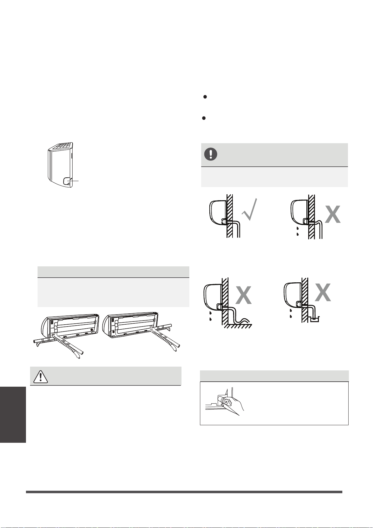
Step 4: Prepare refrigerant piping
Step 5: Connect drain hose
The refrigerant piping is inside an insulating
sleeve attached to the back of the unit. You
must prepare the piping before passing it
through the hole in the wall.
1. Based on the position of the wall hole relative
to the mounting plate, choose the side from
which the piping will exit the unit.
2. If the wall hole is behind the unit, keep the
knock-out panel in place. If the wall hole is to
the side of the indoor unit, remove the plastic
knock-out panel from that side of the unit.
Knock-out Panel
3. If existing connective piping is already
embedded in the wall, proceed directly to
the Connect Drain Hose step. If there is no
embedded piping, connect the indoor unit’s
refrigerant piping to the connective piping
that will join the indoor and outdoor units.
Refer to the Refrigerant Piping Connection
section of this manual for detailed instructions.
NOTE ON PIPING ANGLE
By default, the drain hose is attached to the lefthand side of unit (when you’re facing the back
of the unit). However, it can also be attached to
the right-hand side. To ensure proper drainage,
attach the drain hose on the same side that your
refrigerant piping exits the unit.
Wrap the connection point firmly with Teflon
tape to ensure a good seal and to prevent leaks.
Remove the air filter and pour a small amount
of water into the drain pan to make sure that
water flows from the unit smoothly.
NOTE ON DRAIN HOSE
PLACEMENT
Make sure to arrange the drain hose
according to the following figures.
CORRECT
Make sure there are no kinks
or dent in drain hose to ensure
proper drainage.
.
NOT CORRECT
Kinks in the drain hose
will create water traps.
Be extremely careful not to dent or damage
Indoor Unit
Installation
the piping while bending them away from
the unit. Any dents in the piping will affect
the unit’s performance.
Refrigerant piping can exit the indoor unit from
four different angles:Left-hand side,Right-hand
side, Left rear, Right rear.
CAUTION
NOT CORRECT
Kinks in the drain hose
will create water traps.
PLUG THE UNUSED DRAIN HOLE
NOT CORRECT
Do not place the end of the
drain hose in water or in
containers that collect water.
This will prevent proper
drainage.
To prevent unwanted leaks
you must plug the unused
drain hole with the rubber
plug provided.
Page 22
BEFORE PERFORMING ANY
ELECTRICAL WORK, READ THESE
REGULATIONS
1. All wiring must comply with local and national
electrical codes, regulations and must be
installed by a licensed electrician.
2. All electrical connections must be made
according to the Electrical Connection Diagram
located on the panels of the indoor and outdoor
units.
3. If there is a serious safety issue with the power
supply, stop work immediately. Explain your
reasoning to the client, and refuse to install the
unit until the safety issue is properly resolved.
4. Power voltage should be within 90-110% of
rated voltage. Insufficient power supply can
cause malfunction, electrical shock, or fire.
5. If connecting power to fixed wiring, install a
surge protector and main power switch with
a capacity of 1.5 times the maximum current
of the unit.
6. If connecting power to fixed wiring, a switch
or circuit breaker that disconnects all poles and
has a contact separation of at least 1/8in (3mm)
must be incorporated in the fixed wiring. The
qualified technician must use an approved
circuit breaker or switch.
7. Only connect the unit to an individual branch
circuit outlet. Do not connect another
appliance to that outlet.
8. Make sure to properly ground the air conditioner.
9. Every wire must be firmly connected. Loose
wiring can cause the terminal to overheat,
resulting in product malfunction and possible fire.
Do not let wires touch or rest against refrigerant
10.
tubing, the compressor, or any moving parts
within the unit.
If the unit has an auxiliary electric heater, it must
11.
be installed at least 1 meter (40in) away from
any combustible materials.
12.
To avoid getting an electric shock, never touch
the electrical components soon after the power
supply has been turned off. After turning off
the power, always wait 10 minutes or more
before you touch the electrical components.
WARNING
BEFORE PERFORMING ANY ELECTRICAL
OR WIRING WORK, TURN OFF THE
MAIN POWER TO THE SYSTEM.
Step 6: Connect signal cable
The signal cable enables communication between
the indoor and outdoor units. You must first
choose the right cable size before preparing it for
connection.
Cable Types
•
Indoor Power Cable
H05VV-F or H05V2V2-F
•
Outdoor Power Cable:
•
Signal Cable: H07RN-F
Minimum Cross-Sectional Area of
Power and Signal Cables (For reference)
Rated Current of
Appliance (A)
> 3 and ≤ 6
> 6 and ≤ 10
> 10 and ≤ 16
> 16 and ≤ 25
> 25 and ≤ 32
> 32 and ≤ 40
CHOOSE THE RIGHT CABLE SIZE
The size of the power supply cable, signal
cable, fuse, and switch needed is determined
by the maximum current of the unit. The
maximum current is indicated on the nameplate
located on the side panel of the unit. Refer to
this nameplate to choose the right cable, fuse,
or switch.
(if applicable):
H07RN-F
Nominal Cross-Sectional
Area (mm²)
0.75
1
1.5
2.5
4
6
Indoor Unit
Installation
Page 23
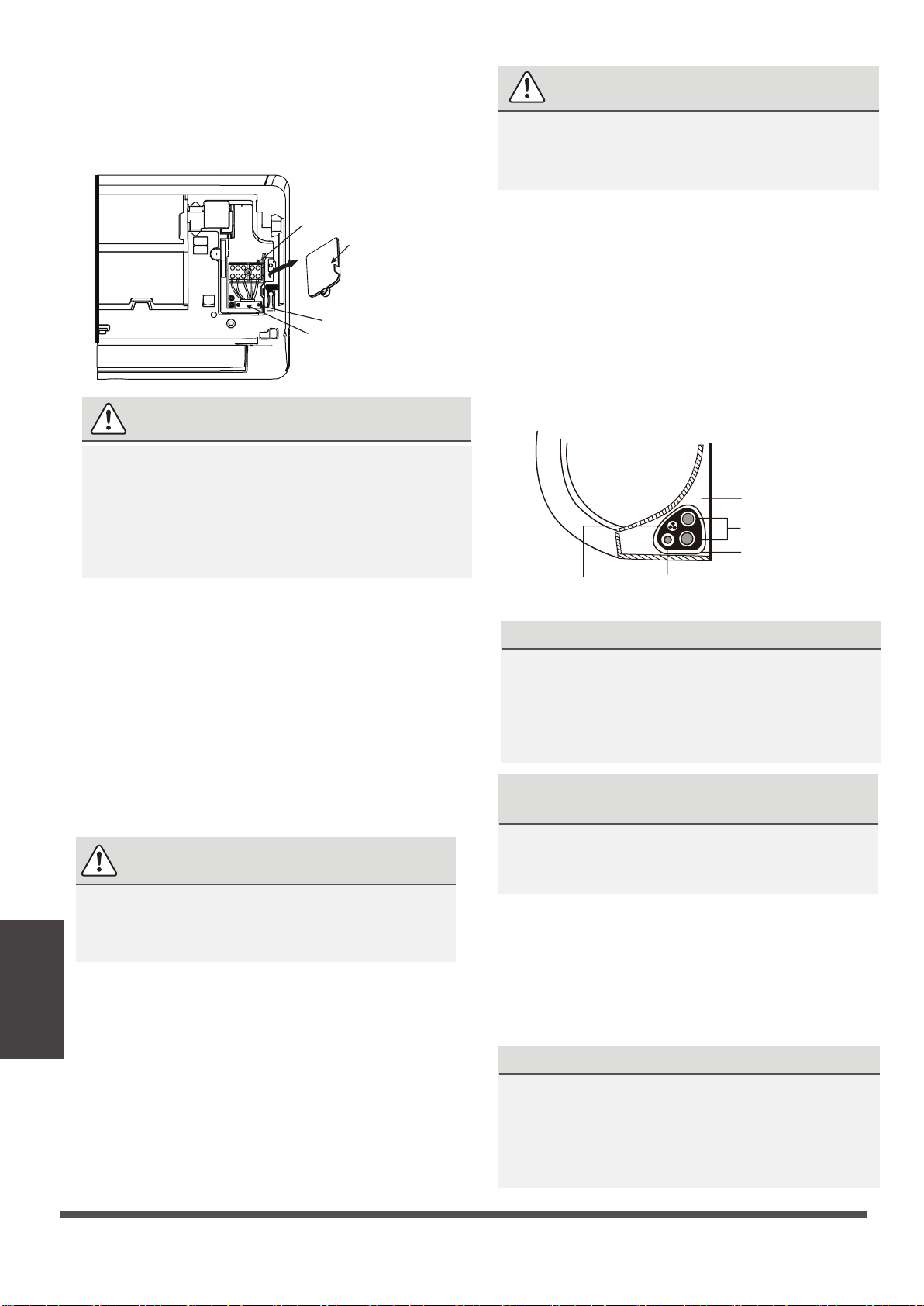
pen front panel of the indoor unit.
O
1.
Using a screwdriver, open the wire box cover
2.
on the right side of the unit. This will reveal
the terminal block.
NOTE ABOUT WIRING
THE WIRING CONNECTION PROCESS MAY
DIFFER SLIGHTLY BETWEEN UNITS AND
REGIONS.
3.
4.
5. Feed the signal wire through this slot, from
6. Facing the front of the unit, connect the wire
Indoor Unit
Installation
7.
8.
Terminal block
Wire cover
Screw
Cable clamp
WARNING
ALL WIRING MUST BE PERFORMED
STRICTLY IN ACCORDANCE WITH THE
WIRING DIAGRAM LOCATED ON THE
BACK OF THE INDOOR UNIT S FRONT
’
PANEL .
Unscrew the cable clamp below the terminal
block and place it to the side.
Facing the back of the unit, remove the plastic
panel on the bottom left-hand side.
the back of the unit to the front.
according to the indoor unit’s wiring diagram,
connect the u-lug and firmly screw each wire
to its corresponding terminal.
CAUTION
DO NOT MIX UP LIVE AND NULL WIRES
This is dangerous, and can cause the air
conditioning unit to malfunction.
After checking to make sure every connection
is secure, use the cable clamp to fasten the
signal cable to the unit. Screw the cable clamp
down tightly.
Replace the wire cover on the front of the
unit, and the plastic panel on the back.
Step 7: Wrappiping and cables
Before passing the piping, drain hose, and the
signal cable through the wall hole, you must
bundle them together to save space, protect
them, and insulate them(Not applicable in
North America).
1.
Bundle the drain hose, refrigerant pipes, and
signal cable as shown below:
Indoor Unit
Space behind unit
Refrigerant piping
Insulation tape
Signal wire
Drain hose
DRAIN HOSE MUST BE ON BOTTOM
Make sure that the drain hose is at the bottom
of the bundle. Putting the drain hose at the
top of the bundle can cause the drain pan
to overflow, which can lead to fire or water
damage.
DO NOT INTERTWINE SIGNAL CABLE WITH
OTHER WIRES
While bundling these items together, do not
intertwine or cross the signal cable with any
other wiring.
2. Using adhesive vinyl tape, attach the drain
hose to the underside of the refrigerant pipes.
3.
Using insulation tape, wrap the signal wire,
refrigerant pipes, and drain hose tightly
together. Double-check that all items are
bundled.
DO NOT WRAP ENDS OF PIPING
When wrapping the bundle, keep the ends
of the piping unwrapped. You need to access
them to test for leaks at the end of the
installation process (refer to Electrical Checks
and Leak Checks section of this manual).
Page 24

Step 8: Mount indoor unit
If you installed new connective piping to the
outdoor unit, do the following:
1.
If you have already passed the refrigerant
piping through the hole in the wall, proceed
to Step 4.
2.
Otherwise, double-check that the ends of the
refrigerant pipes are sealed to prevent dirt or
foreign materials from entering the pipes.
3.
Slowly pass the wrapped bundle of refrigerant
pipes, drain hose, and signal wire through the
hole in the wall.
4.
Hook the top of the indoor unit on the upper
hook of the mounting plate.
5.
Check that unit is hooked firmly on mounting
by applying slight pressure to the left and
right-hand sides of the unit. The unit should
not jiggle or shift.
6.
Using even pressure, push down on the
bottom half of the unit. Keep pushing down
until the unit snaps onto the hooks along the
bottom of the mounting plate.
7.
Again, check that the unit is firmly mounted
by applying slight pressure to the left and the
right-hand sides of the unit.
If refrigerant piping is already embedded in
the wall, do the following:
1.
Hook the top of the indoor unit on the upper
hook of the mounting plate.
3.
Connect drain hose and refrigerant piping
(refer to Refrigerant Piping Connection
section of this manual for instructions).
4.
Keep pipe connection point exposed to
perform the leak test (refer to Electrical
Checks and Leak Checks section of this
manual).
5.
After the leak test, wrap the connection point
with insulation tape.
6.
Remove the bracket or wedge that is propping
up the unit.
7.
Using even pressure, push down on the
bottom half of the unit. Keep pushing down
until the unit snaps onto the hooks along the
bottom of the mounting plate.
UNIT IS ADJUSTABLE
Keep in mind that the hooks on the mounting
plate are smaller than the holes on the back of
the unit. If you find that you don’t have ample
room to connect embedded pipes to the indoor
unit, the unit can be adjusted left or right by
about 30-50mm (1.25-1.95in), depending on
the model.
30-50mm
(1.2-1.95in)
Move to left or right
30-50mm
(1.2-1.95in)
2.
Use a bracket or wedge to prop up the unit,
giving you enough room to connect the
refrigerant piping, signal cable, and drain
hose.
Page 25
Installation
Indoor Unit
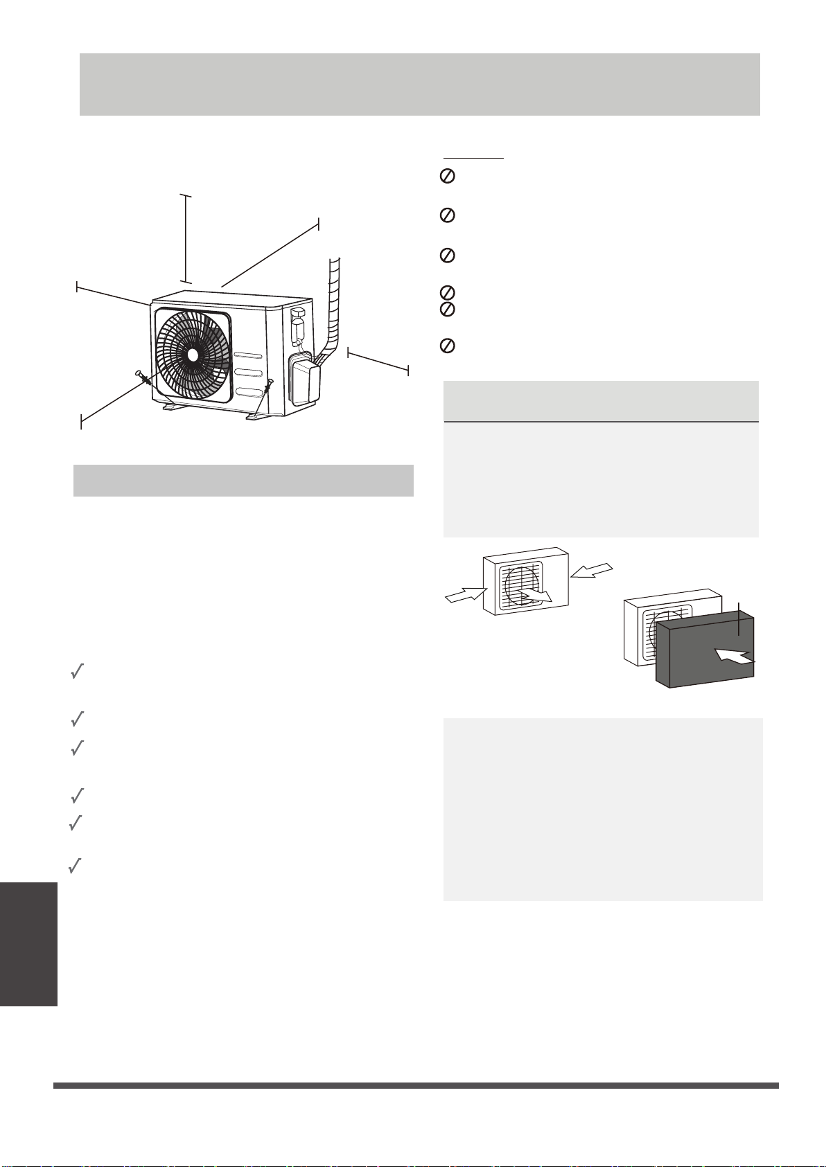
Outdoor Unit Installation
Install the unit by following local codes and
DO NOT
between different regions.
evoba )ni42( mc06
regulations , there may be differ slightly
Near a public street, crowded areas, or
where noise from the unit will disturb others
30cm (12in)
30cm (12in)
on left
from back wall
Near any source of combustible gas
In a location that is exposed to large
amounts of dust
In a location exposed to a excessive amounts
60cm (24in)
on right
of salty air
SPECIAL CONSIDERATIONS FOR EXTREME
WEATHER
200cm (79in)
in front
If the unit is exposed to heavy wind:
Install unit so that air outlet fan is at a 90°
Installation Instructions – Outdoor unit
angle to the direction of the wind. If needed,
build a barrier in front of the unit to protect it
Step 1: Select installation location
from extremely heavy winds.
See Figures below.
Before installing the outdoor unit, you must
choose an appropriate location. The following are
standards that will help you choose an appropriate
location for the unit.
Proper installation locations meet the
Strong
wind
following standards:
install unit in the following locations:
Near an obstacle that will block air inlets
and outlets
Near animals or plants that will be harmed
by hot air discharge
Installation
Strong wind
Wind Baffle
Where snowfall is anticipated, raise the
Outdoor Unit
Installation
Meets all spatial requirements shown in
Installation Space Requirements above.
Good air circulation and ventilation
Firm and solid—the location can support the
unit and will not vibrate
Noise from the unit will not disturb others
Protected from prolonged periods of direct
sunlight or rain
unit above the base pad to prevent ice
buildup and coil damage. Mount the unit
high enough to be above the average
accumulated area snowfall. The minimum
height must be 18 inches
Strong wind
If the unit is frequently exposed to heavy
rain or snow:
Build a shelter above the unit to protect
it from the rain or snow. Be careful not to
obstruct air flow around the unit.
If the unit is frequently exposed to salty air
(seaside):
Use outdoor unit that is specially designed to
resist corrosion.
Page 26

Step 2: Install drain joint(Heat pump unit only)
A
W
B
Before bolting the outdoor unit in place, you must
install the drain joint at the bottom of the unit.
Note that there are two different types of drain
joints depending on the type of outdoor unit.
If the drain joint comes with a rubber seal
(see Fig. A ), do the following:
1.
Fit the rubber seal on the end of the drain joint
that will connect to the outdoor unit.
2.
Insert the drain joint into the hole in the base
pan of the unit.
3.
Rotate the drain joint 90° until it clicks in place
facing the front of the unit.
4.
Connect a drain hose extension (not included)
to the drain joint to redirect water from the
unit during heating mode.
If the drain joint doesn’t come with a rubber
seal (see Fig. B ), do the following:
1.
Insert the drain joint into the hole in the base
pan of the unit. The drain joint will click in
place.
2.
Connect a drain hose extension (not included)
to the drain joint to redirect water from the
unit during heating mode.
Step 3: Anchor outdoor unit
The outdoor unit can be anchored to the
ground or to a wall-mounted bracket with
bolt(M10). Prepare the installation base of the
unit according to the dimensions below.
UNIT MOUNTING DIMENSIONS
The following is a list of different outdoor
unit sizes and the distance between their
mounting feet. Prepare the installation base
of the unit according to the dimensions
below.
Air inlet
Air inlet
D
Air outlet
Base pan hole of
outdoor unit
Seal
Seal
Drain joint
(A) (B)
IN COLD CLIMATES
In cold climates, make sure that the drain hose
is as vertical as possible to ensure swift water
drainage. If water drains too slowly, it can
freeze in the hose and flood the unit.
W
H
Outdoor Unit
Installation
Page 27
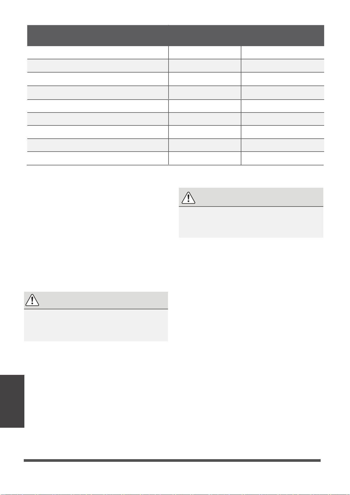
Outdoor Unit Dimensions (mm)
Mounting Dimensions
W x H x D
681x434x285 (26.8”x17”x11.2”) 460 (18.10”) 292 (11.49”)
700x550x270 (27.5”x21.6”x10.62”) 450 (17.7”) 260 (10.24”)
700x550x275 (27.5”x21.6”x10.82”)
720x495x270 (28.3”x19.5”x10.6”)
728x555x300 (28.66”x21.85”x11.81”)
770x555x300 (30.3”x21.85”x11.81”)
800x554x333 (31.5”x21.8”x13.1”)
845x702x363 (33.25”x27.63”x14.29”)
946x810x420 (37.21”x31.9”x16.53”)
If you will install the unit on the ground or
on a concrete mounting platform, do the
following:
1. Mark the positions for four expansion bolts
based on dimensions chart.
2. Pre-drill holes for expansion bolts.
3. Place a nut on the end of each expansion bolt.
4. Hammer expansion bolts into the pre-drilled
holes.
5. Remove the nuts from expansion bolts, and
place outdoor unit on bolts.
6. Put washer on each expansion bolt, then
replace the nuts.
7. Using a wrench, tighten each nut until snug.
WARNING
WHEN DRILLING INTO CONCRETE, EYE
PROTECTION IS RECOMMENDED AT ALL
TIMES.
Distance A (mm) Distance B (mm)
450 (17.7”)
452 (17.7”)
452 (17.79”)
487 (19.2”)
514 (20.24”)
540 (21.26”)
673 (26.5”)
260 (10.24”)
255 (10.0”)
302(11.89”)
298 (11.73”)
340 (13.39”)
350 (13.8”)
403 (15.87”)
If you will install the unit on a wall-mounted
bracket , do the following:
CAUTION
Make sure that the wall is made of solid brick,
concrete, or of similarly strong material. The
wall must be able to support at least four
times the weight of the unit.
1.Mark the position of bracket holes based on
dimensions chart.
2. Pre-drill the holes for the expansion bolts.
3. Place a washer and nut on the end of each
expansion bolt.
4. Thread expansion bolts through holes in
mounting brackets, put mounting brackets
in position, and hammer expansion bolts into
the wall.
5. Check that the mounting brackets are level.
6. Carefully lift unit and place its mounting feet
on brackets.
7. Bolt the unit firmly to the brackets.
8.
If allowed, install the unit with rubber
gaskets to reduce vibrations and noise.
Outdoor Unit
Installation
Page 28
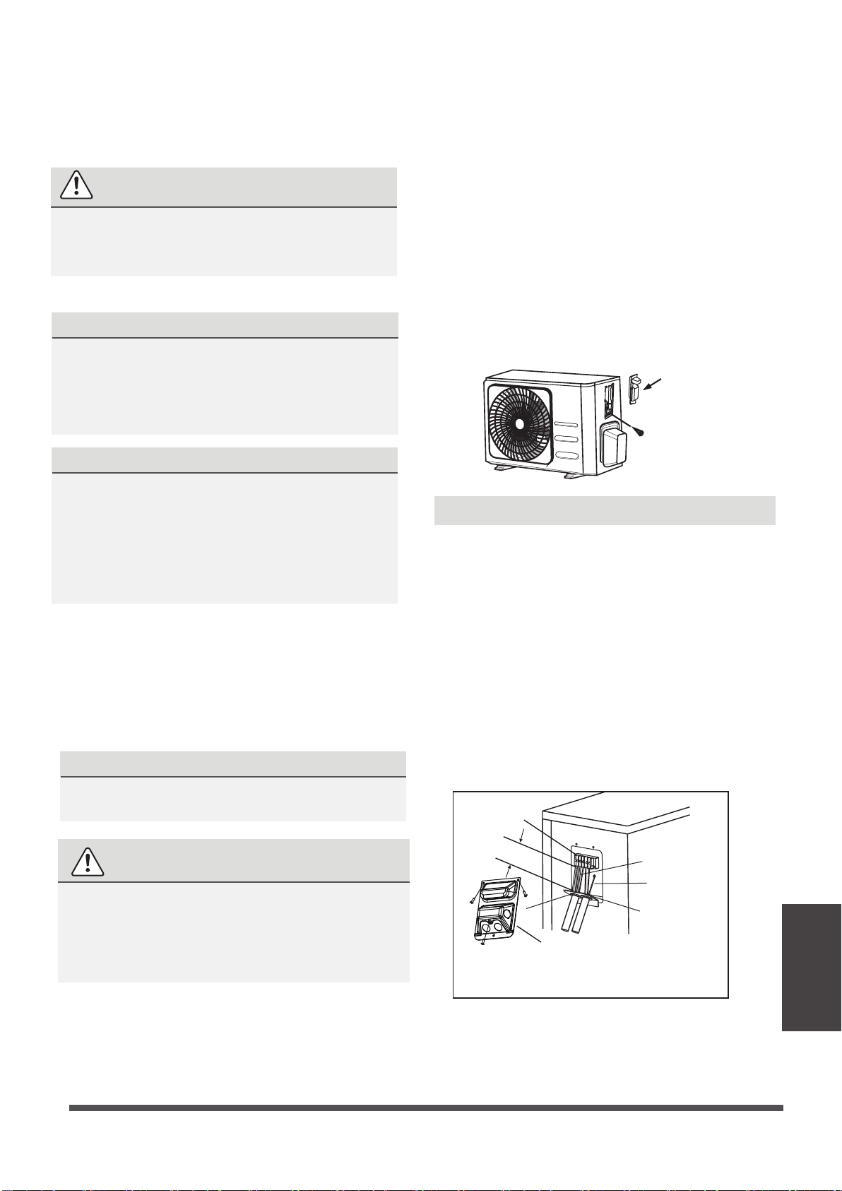
Step 4: Connect signal and power cables
The outside unit’s terminal block is protected by
an electrical wiring cover on the side of the unit.
A comprehensive wiring diagram is printed on
the inside of the wiring cover.
WARNING
BEFORE PERFORMING ANY ELECTRICAL
OR WIRING WORK, TURN OFF THE MAIN
POWER TO THE SYSTEM.
1. Prepare the cable for connection:
USE THE RIGHT CABLE
•
Indoor Power Cable (if applicable): H05VV-F
or H05V2V2-F
•
Outdoor Power Cable: H07RN-F
•
Signal Cable: H07RN-F
CHOOSE THE RIGHT CABLE SIZE
2. Unscrew the electrical wiring cover and remove it.
3. Unscrew the cable clamp below the terminal
block and place it to the side.
4. Connect the wire according to the wiring
diagram, and firmly screw the u-lug of each
wire to its corresponding terminal.
5. After checking to make sure every connection is
secure, loop the wires around to prevent rain
water from flowing into the terminal.
6. Using the cable clamp, fasten the cable to the
unit. Screw the cable clamp down tightly.
7. Insulate unused wires with PVC electrical tape.
Arrange them so that they do not touch any
electrical or metal parts.
8. Replace the wire cover on the side of the unit,
and screw it in place.
Cover
Screw
The size of the power supply cable, signal cable,
fuse, and switch needed is determined by the
maximum current of the unit. The maximum
current is indicated on the nameplate located on
the side panel of the unit. Refer to this nameplate
to choose the right cable, fuse, or switch.
a. Using wire strippers, strip the rubber
jacket from both ends of cable to reveal
about 40mm (1.57in) of the wires inside.
b. Strip the insulation from the ends of the
wires.
c. Using a wire crimper, crimp u-lugs on the
ends of the wires.
PAY ATTENTION TO LIVE WIRE
While crimping wires, make sure you clearly
distinguish the Live (“L”) Wire from other wires.
WARNING
ALL WIRING WORK MUST BE PERFORMED
STRICTLY IN ACCORDANCE WITH THE
WIRING DIAGRAM LOCATED INSIDE OF
WIRE COVER OF THE OUTDOOR UNIT .
In North America
1. Remove the wire cover from the unit by
loosening the 3 screws.
2. Dismount caps on the conduit panel.
3. Temperarily mount the conduit tubes(not
included) on the conduit panel.
4. Properly connect both the power supply and
low voltage lines to the corresponding
terminals on the terminal block.
5. Ground the unit in accordance with local codes.
6. Be sure to size each wire allowing several inches
longer than the required length for wiring.
7. Use lock nuts to secure the conduit tubes.
Terminal block
Over 1.57in.(40mm)
G
Wire Cover
Please select the appropriate through-hole according
to the diameter of the wire.
Connecting cable
Power supply cord
Conduit panel
Installation
Outdoor Unit
Page 29

Refrigerant Piping Connection
When connecting refrigerant piping, do not
refrigerant enter the unit. The presence of other gases or substances will lower the unit’s capacity,
and can cause abnormally high pressure in the refrigeration cycle. This can cause explosion and
injury.
Note on Pipe Length
The length of refrigerant piping will affect the performance and energy efficiency of the unit. Nominal
efficiency is tested on units with a pipe length of 5 meters (16.5ft). A minimum pipe run of 3 metres is
required to minimise vibration & excessive noise.
In special tropical area, for the R290 refrigerant models, no refrigerant can be added and the maximum
length of refrigerant pipe should not exceed 10 meters(32.8ft).
Refer to the table below for specifications on the maximum length and drop height of piping.
Maximum Length and Drop Height of Refrigerant Piping per Unit Model
Model Capacity (BTU/h) Max. Length (m) Max. Drop Height (m)
let substances or gases other than the specified
R410A,R32 Inverter Split Air
R22 Fixed-speed
Split Air Conditioner
Connection Instructions –
Step 1: Cut pipes
When preparing refrigerant pipes, take extra
care to cut and flare them properly. This will
ensure efficient operation and minimize the
need for future maintenance.
1. Measure the distance between the indoor
and outdoor units.
2. Using a pipe cutter, cut the pipe a little longer
than the measured distance.
3. Make sure that the pipe is cut at a perfect 90°
Refrigerant piping
Connection
angle.
Conditioner
Split Air Conditioner
R410A, R32 Fixed-speed
< 15,000
≥ 15,000 and < 24,000 30 (98.5ft) 20 (66ft)
≥ 24,000 and < 36,000 50 (164ft) 25 (82ft)
< 18,000
≥ 18,000 and < 21,000
≥ 21,000 and < 35,000 10(33ft)
≥ 18,000 and < 36,000
25 (82ft) 10 (33ft)
10 (33ft) 5 (16ft)
15 (49ft)
20 (66ft)
20 (66ft)
25 (82ft)
8(26ft)
8(26ft)< 18,000
10(33ft)
Refrigerant Piping
90°
Oblique Rough Warped
DO NOT DEFORM PIPE
WHILE CUTTING
Be extra careful not to damage, dent, or
deform the pipe while cutting. This will
drastically reduce the heating efficiency
of the unit.
Page 30
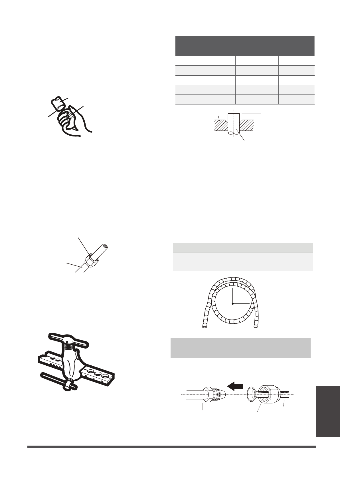
Step 2: Remove burrs
Burrs can affect the air-tight seal of refrigerant
piping connection. They must be completely
removed.
1.
Hold the pipe at a downward angle to prevent
burrs from falling into the pipe.
2.
Using a reamer or deburring tool, remove all
burrs from the cut section of the pipe.
Pipe
Reamer
PIPING EXTENSION BEYOND FLARE FORM
Outer Diameter of
Pipe (mm)
Ø 6.35 (Ø 0.25”)
Ø 9.52 (Ø 0.375”)
Ø12.7 (
Ø 16 ( Ø 0.63”)
Ø 19 ( Ø 0.75”)
Ø 0.5”) 1.0 (0.04”) 1.8 (0.07”)
0.7 (0.0275”) 1.3 (0.05”)
1.0 (0.04”)
2.0 (0.078”) 2.2 (0.086”)
2.0 (0.078”) 2.4 (0.094”)
A (mm)
Min. Max.
1.6 (0.063”)
Max.
Point down
Step 3: Flare pipe ends
Proper flaring is essential to achieve an airtight
seal.
1.
After removing burrs from cut pipe, seal
the ends with PVC tape to prevent foreign
materials from entering the pipe.
2.
Sheath the pipe with insulating material.
3.
Place flare nuts on both ends of pipe. Make
sure they are facing in the right direction,
because you can’t put them on or change
their direction after flaring.
Flare nut
Copper pipe
Flare form
6.
Place flaring tool onto the form.
7.
Turn the handle of the flaring tool clockwise
A
Pipe
until the pipe is fully flared.
8.
Remove the flaring tool and flare form, then
inspect the end of the pipe for cracks and
even flaring.
Step 4: Connect pipes
When connecting refrigerant pipes, be careful
not to use excessive torque or to deform the
piping in any way. You should first connect the
low-pressure pipe, then the high-pressure pipe.
MINIMUM BEND RADIUS
When bending connective refrigerant piping,
the minimum bending radius is 10cm.
4.
Remove PVC tape from ends of pipe when
ready to perform flaring work.
5.
Clamp flare form on the end of the pipe.
The end of the pipe must extend beyond the
edge of the flare form in accordance with the
dimensions shown in the table below.
≥10cm (4in)
Radius
Instructions for Connecting Piping to
Indoor Unit
1.
Align the center of the two pipes that you will
connect.
Indoor unit tubing Flare nut Pipe
Refrigerant piping
Connection
Page 31

2.
Tighten the flare nut as tightly as possible by
hand.
3.
Using a spanner, grip the nut on the unit
tubing.
4.
While firmly gripping the nut on the unit
tubing, use a torque wrench to tighten the
flare nut according to the torque values in the
Torque Requirements table below. Loosen
the flaring nut slightly, then tighten again.
TORQUE REQUIREMENTS
Outer Diameter of Pipe
(mm)
Ø 6.35 (Ø 0.25”)
Ø 9.52 (Ø 0.375”)
Ø 12.7 (Ø 0.5”)
Ø 16 (Ø 0.63”)
Ø 19 ( Ø 0.75”)
Tightening Torque
(N•m)
18~20(180~200kgf.cm)
32~39(320~390kgf.cm)
49~59(490~590kgf.cm)
57~71(570~710kgf.cm)
67~101(670~1010kgf.cm)
Flare dimension(B)
(mm)
8.4~8.7 (0.33~0.34”)
13.2~13.5 (0.52~0.53”)
16.2~16.5 (0.64~0.65”)
19.2~19.7 (0.76~0.78”)
23.2~23.7 (0.91~0.93”)
Flare shape
°
4
±
90
45
B
R0.4~0. 8
DO NOT USE EXCESSIVE TORQUE
Excessive force can break the nut or damage the refrigerant piping. You must not exceed
torque requirements shown in the table above.
Instructions for Connecting Piping to Outdoor Unit
1.
Unscrew the cover from the packed valve on
the side of the outdoor unit.
2.
Remove protective caps from ends of valves.
3.
Align flared pipe end with each valve, and
tighten the flare nut as tightly as possible by
hand.
6.
Loosen the flaring nut slightly, then tighten
again.
7.
Repeat Steps 3 to 6 for the remaining pipe.
USE SPANNER TO GRIP MAIN
BODY OF VALVE
°
±
2
4.
Using a spanner, grip the body of the valve.
Do not grip the nut that seals the service
valve.
Refrigerant piping
Connection
5.
While firmly gripping the body of the valve,
use a torque wrench to tighten the flare nut
according to the correct torque values.
Page 32
Torque from tightening the flare nut can snap
off other parts of valve.
Valve cover
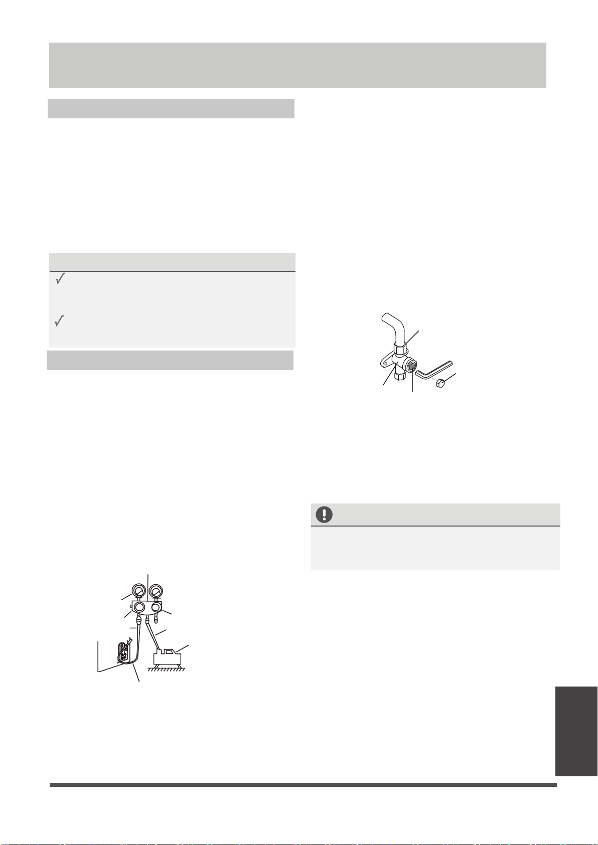
Air Evacuation
Preparations and Precautions
Air and foreign matter in the refrigerant circuit can
cause abnormal rises in pressure, which can damage
the air conditioner, reduce its efficiency, and cause
injury. Use a vacuum pump and manifold gauge to
evacuate the refrigerant circuit, removing any
non-condensable gas and moisture from the system.
Evacuation should be performed upon initial
installation and when unit is relocated.
BEFORE PERFORMING EVACUATION
Check to make sure the connective pipes
between the indoor and outdoor units
are connected properly .
Check to make sure all wiring is connected
properly.
8.
9.
10.
11.
If there is a change in system pressure, refer
to Gas Leak Check section for information
on how to check for leaks. If there is no
change in system pressure, unscrew the cap
from the packed valve (high pressure valve).
Insert hexagonal wrench into the packed valve
(high pressure valve) and open the valve by
turning the wrench in a 1/4 counterclockwise
turn. Listen for gas to exit the system, then
close the valve after 5 seconds.
Watch the Pressure Gauge for one minute
to make sure that there is no change in
pressure. The Pressure Gauge should read
slightly higher than atmospheric pressure.
Remove the charge hose from the service port.
Flare nut
Evacuation Instructions
1.
Connect the charge hose of the manifold
gauge to service port on the outdoor unit’s
low pressure valve.
2.
Connect another charge hose from the
manifold gauge to the vacuum pump.
3.
Open the Low Pressure side of the manifold
gauge. Keep the High Pressure side closed.
4.
Turn on the vacuum pump to evacuate the
system.
5.
Run the vacuum for at least 15 minutes, or
until the Compound Meter reads -76cmHG
5
(-10 Pa).
Low pressure
valve
Pressure hose /
Charge hose
Compound
gauge
-76cmHg
Manifold Gauge
Pressure gauge
High pressure
valve
Charge hose
V
acuum
pump
Cap
valve body
12.
Using hexagonal wrench, fully open both the
valve stem
high pressure and low pressure valves.
13.
Tighten valve caps on all three valves (service
port, high pressure, low pressure) by hand.
You may tighten it further using a torque
wrench if needed.
OPEN VALVE STEMS GENTLY
When opening valve stems, turn the hexagonal
wrench until it hits against the stopper. Do not
try to force the valve to open further.
Low pressure valve
6.
Close the Low Pressure side of the manifold
gauge, and turn off the vacuum pump.
Wait for 5 minutes, then check that there
7.
has been no change in system pressure.
Page 33
Air Evacuation
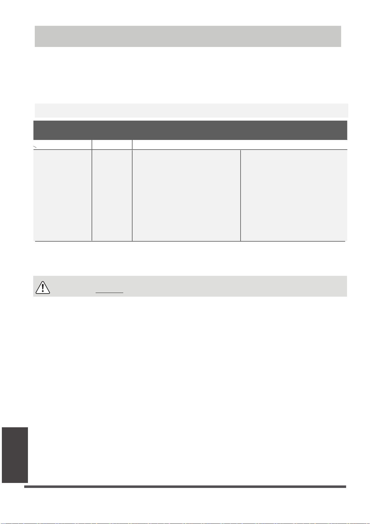
Note on Adding Refrigerant
Some systems require additional charging depending on pipe lengths. The standard pipe length varies
according to local regulations. For example, in North America, the standard pipe length is 7.5m (25’).
In other areas, the standard pipe length is 5m (16‘). The refrigerant should be charged from the service
port
on the outdoor unit’s low pressure valve.
The additional refrigerant to be charged can be
calculated using the following formula:
ADDITIONAL REFRIGERANT PER PIPE LENGTH
Connective Pipe
Length (m)
< Standard pipe length Vacuum Pump N/A
> Standard pipe
length
Air Purging
Method
Vacuum Pump
Additional Refrigerant
Liquid Side: Ø 6.35 (ø 0.25”)
R32:
(Pipe length – standard length) x 12g/m
(Pipe length – standard length) x 0.13oZ/ft
R290:
(Pipe length – standard length) x 10g/m
(Pipe length – standard length) x 0.10oZ/ft
R410A:
(Pipe length – standard length) x 15g/m
(Pipe length – standard length) x 0.16oZ/ft
R22:
(Pipe length – standard length) x 20g/m
(Pipe length – standard length) x 0.21oZ/ft
Liquid Side: Ø 9.52 (ø 0.375”)
R32:
(Pipe length – standard length) x 24g/m
(Pipe length – standard length) x 0.26oZ/ft
R290:
(Pipe length – standard length) x 18g/m
(Pipe length – standard length) x 0.19oZ/ft
R410A:
(Pipe length – standard length) x 30g/m
(Pipe length – standard length) x 0.32oZ/ft
R22:
(Pipe length – standard length) x 40g/m
(Pipe length – standard length) x 0.42oZ/ft
For R290 refrigerant unit, the total amount of refrigerant to be charged is no more than:
387g(<=9000Btu/h), 447g(>9000Btu/h and <=12000Btu/h), 547g(>12000Btu/h and <=18000Btu/h),
632g(>18000Btu/h and <=24000Btu/h).
CAUTION
DO NOT mix refrigerant types.
Air Evacuation
Page 34
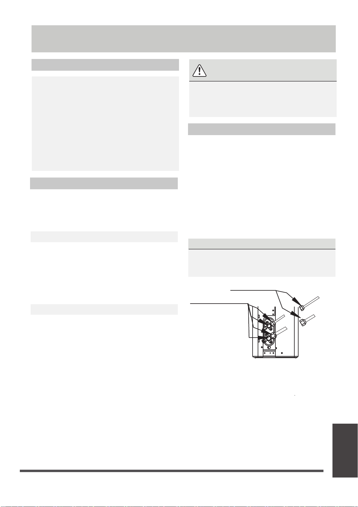
Electrical and Gas Leak Checks
Before Test Run
Only perform test run after you have completed
the following steps:
•
Electrical Safety Checks – Confirm that
the unit’s electrical system is safe and
operating properly
•
Gas Leak Checks – Check all flare nut
connections and confirm that the system is
not leaking
•
Confirm that gas and liquid (high and low
pressure) valves are fully open
Electrical Safety Checks
After installation, confirm that all electrical wiring
is installed in accordance with local and national
regulations, and according to the Installation
Manual.
BEFORE TEST RUN
Check Grounding Work
Measure grounding resistance by visual detection
and with grounding resistance tester. Grounding
resistance must be less than 0.1Ω.
Note: This may not be required for some
locations in the US.
DURING TEST RUN
WARNING – RISK OF
ELECTRIC SHOCK
ALL WIRING MUST COMPLY WITH LOCAL
AND NATIONAL ELECTRICAL CODES,
AND MUST BE INSTALLED BY A LICENSED
ELECTRICIAN.
Gas Leak Checks
There are two different methods to check for gas
leaks.
Soap and Water Method
Using a soft brush, apply soapy water or liquid
detergent to all pipe connection points on the
indoor unit and outdoor unit. The presence of
bubbles indicates a leak.
Leak Detector Method
If using leak detector, refer to the device’s
operation manual for proper usage instructions.
AFTER PERFORMING GAS LEAK CHECKS
After confirming that the all pipe connection
points DO NOT leak, replace the valve cover on
the outside unit.
Check-point of indoor unit
Check-point of outdoor unit
D
Check for Electrical Leakage
During the Test Run, use an electroprobe and
multimeter to perform a comprehensive electrical
leakage test.
If electrical leakage is detected, turn off the unit
immediately and call a licensed electrician to find
and resolve the cause of the leakage.
Note: This may not be required for some
locations in the US.
B
A
A: Low pressure stop valve
B: High pressure stop valve
C& D: Indoor unit flare nuts
Page 35
C
Electrical and
Gas Leak Checks

Test Run
Test Run Instructions
You should perform the Test Run for at least 30
minutes.
1.
Connect power to the unit.
2.
Press the ON/OFF button on the remote
controller to turn it on.
3.
Press the MODE button to scroll through the
following functions, one at a time:
•
COOL – Select lowest possible temperature
•
HEAT – Select highest possible temperature
4.
Let each function run for 5 minutes, and
perform the following checks:
List of Checks to Perform PASS/FAIL
No electrical leakage
Unit is properly grounded
All electrical terminals
properly covered
Indoor and outdoor units
are solidly installed
All pipe connection
points do not leak
Water drains properly
from drain hose
All piping is properly
insulated
Outdoor
(2):
Indoor
(2):
DOUBLE-CHECK PIPE CONNECTIONS
During operation, the pressure of the
refrigerant circuit will increase. This may
reveal leaks that were not present during your
initial leak check. Take time during the Test
Run to double-check that all refrigerant pipe
connection points do not have leaks. Refer to
Gas Leak Check section for instructions.
5.
After the Test Run is successfully completed,
and you confirm that all checks points in List
of Checks to Perform have PASSED, do the
following:
a.
Using remote control, return unit to
normal operating temperature.
b.
Using insulation tape, wrap the indoor
refrigerant pipe connections that you
left uncovered during the indoor unit
installation process.
IF AMBIENT TEMPERATURE IS BELOW 17°C
(62°F)
You can’t use the remote controller to turn
on the COOL function when the ambient
temperature is below 17°C. In this instance,
you can use the MANUAL CONTROL button
to test the COOL function.
1.
Lift the front panel of the indoor unit, and
raise it until it clicks in place.
2.
The MANUAL CONTROL button is located
on the right-hand side of the unit. Press it 2
times to select the COOL function.
3.
Perform Test Run as normal.
Test Run
Unit performs COOL
function properly
Unit performs HEAT
function properly
Indoor unit louvers
rotate properly
Indoor unit responds to
remote controller
Page 36
Manual control button

Impedance Information
(Applicable to some countries of Middle East Area only)
This appliance MST2ABD-18CR-QB9 can be connected only to a supply with system impedance
no more than 0.163Ω. In case necessary, please consult your supply authority for system
impedance information.
This appliance MST2ABE-22CR-QB9 can be connected only to a supply with system impedance
no more than 0.186Ω. In case necessary, please consult your supply authority for system
impedance information.
This appliance MST2ABF-30CR-QB6W can be connected only to a supply with system impedance
no more than 0.045Ω. In case necessary, please consult your supply authority for system
impedance information.
This appliance MST2ABF-30CR-QB9W can be connected only to a supply with system impedance
no more than 0.085Ω. In case necessary, please consult your supply authority for system
impedance information.
This appliance MSTABD-18CR-QB8 can be connected only to a supply with system impedance
no more than 0.188Ω. In case necessary, please consult your supply authority for system
impedance information.
This appliance MST2ABF-32CR-QC0W can be connected only to a supply with system impedance
no more than 0.057Ω. In case necessary, please consult your supply authority for system
impedance information.
This appliance MSTABB-12CRN1-B1 can be connected only to a supply with system impedance
no more than 0.261Ω. In case necessary, please consult your supply authority for system
impedance information.
Page 37

The design and specifications are subject to change without prior notice for
product improvement. Consult with the sales agency or manufacturer for details.
Any updates to the manual will be uploaded to the service website, please check
for the latest version.
Test Run
CS001UI-AB
16122000008274
20190303

SAFETY MANUAL
IMPORTANT NOTE:
Read this manual carefully before installing
or operating your new air conditioning
unit. Make sure to save this manual for
future reference.
CAUTION: Risk of fire
Precautions
Safety Precautions
Read Safety Precautions Before Operation and Installation
Incorrect installation due to ignoring instructions can cause serious damage or injury.
WARNING
1.
Installation (Space)
- That the installation of pipe-work shall be kept to a minimum.
- That pipe-work shall be protected from physical damage.
- Where refrigerant pipes shall be compliance with national gas regulations.
- That mechanical connections shall be accessible for maintenance purposes.
- In cases that require mechanical ventilation, ventilation openings shall be kept clear of obstruction.
- When disposing of the product is used, be based on national regulations, properly processed.
2. Servicing
- Any person who is involved with working on or breaking into a refrigerant circuit should
hold a current valid certificate from an industry-accredited assessment authority, which
authorises their competence to handle refrigerants safely in accordance with an industry
recognised assessment specification.
3. Maintenance and repair requiring the assistance of other skilled personnel shall be carried
out under the supervision of the person competent in the use of flammable refrigerants.
4. Do not use means to accelerate the defrosting process or to clean, other than those
recommended by the manufacturer.
5. The appliance shall be stored in a room without continuously operating ignition sources
(for example: open flames,an operating gas appliance or an operating electric heater)
6. Be more careful that foreign matter(oil, water,etc) does not enter the piping. Also, when
storing the piping, securely seal the opening by pinching, taping, etc.
7. Do not pierce or burn.
8.
Be aware that refrigerants may not contain an odour.
9.
All working procedure that affects safety means shall only be carried by competent
persons.
Appliance shall be stored in a well -ventilated area where the room size corresponds to
10.
the room area as specifiec for operation.
11. The appliance shall be stored so as to prevent mechanical damage from occurring.
12. When a FLAMMABLE REFRIGERANT is used, the requirements for installation space of
appliance and /or ventilation requirements are determined according to
-- the mass charge amount(M) used in the appliance,
--the installation location,
--the type of ventilation of the location or of the appliance.
Page 1

The maximun charge in a room shall be in accordance with the following:
m = 2,5 x (LFL) x h x (A)
max
or the required minumum floor area
(5/4)
0
1/2
A
min
to install an applicance with refrigerant charge
M(kg) shall be in accordance with following:
A = (M/(2,5 x (LFL) x h ))
min
(5/4)
2
0
Where.
m
is the allowable maximum charge in a room, in kg;
max
M is the refrigerant charge amount in appliance, in kg;
min
A
is the required minimum room area, in m ;
A
is the room area, in m ;
LFL
is the lower flammable limit, in kg/m ;
h
is the release height, the vertical distance in metres from the floor to the point of
0
2
3
2
release when the appliance is installed;
h
= (hinst+hrel) or 0,6 m whichever is higher
0
h
rel is the release offset in metres from the bottom of the appliance to the point of
release
h
inst is the installed height in metres of the unit
Reference installed heights are given below:
0.0 m for portable and floor mounted;
1.0m for window mounted;
1.8m for wall mounted;
2.2m for ceiling mounted;
If the minimum installed height given by the manufacturer is higher than the reference
installed height, then in addition A
and m
max
for the reference installed height have to
min
be given by the manufacturer. An appliance may have multiple reference installed heights.
In this case, A
min
and m
max
calculations shall be provided for all applicable reference
installed heights.
For appliances serving one or more rooms with an air duct system, the lowest opening of the
duct connection to each conditioned space or any opening of the indoor unit greater than
2
5 cm , at the lowest position to the space, shall be used for h
than 0,6 m. A
min
shall be calculated as a function of the opening heights of the duct to the
0
. However, h0 shall not be less
spaces and the refrigerant charge for the spaces where leaked refrigerant may flow to,
min
considering where the unit is located. All spaces shall have a floor area more than A
.
Page 2

NOTE 1 This formula cannot be used for refrigerants lighter than 42 kg/kmol.
NOTE 2 Some examples of the results of the calculations according to the above formula are
given in Tables 1-1 and 1-2.
NOTE 3 For factory sealed appliances, the nameplate on the unit itself marked the refrigerant
min
charge can be used to calculate A
NOTE 4 For field charged products, calculation of A
.
min
can be based on the installed refrigerant
charge not to exceed the factory specified maximum refrigerant charge.
The maximun charge in a room and the required minumum floor area to install an
applicance, please refer to the “Owner’s Manual & Installation Manual” of the unit.
For specific information on the type of gas and the amount, please refer to the relevant label
on the unit itself
Table.1-1
Refrigerant
Type
R32
R290
Table.1-2
Refrigerant
Type
R32
R290
LFL(kg/m )
0.306
0.038
LFL(kg/m )
0.306
0.038
3
Installation
Height H0(m)
3
Installation
Height H0(m)
Max Refrigerant Charge (kg)
Floor Area (m )
0.6
1.0
1.8
2.2
0.6
1.0
1.8
2.2
4
0.68
1.14
2.05
2.50
0.05 0.07 0.08 0.10 0.11 0.14 0.18
0.08 0.11 0.13 0.16 0.19 0.23 0.30
0.15 0.20 0.24 0.29 0.34 0.41 0.53
0.18 0.24 0.29 0.36 0.41 0.51 0.65
7
0.90
1.51
2.71
3.31
10
1.08
1.80
3.24
3.96
Min. Room Area (m )
Charge Amount in kg
Minimum Room Area ( m )
0.6
1.0
1.8
2.2
0.6
1.0
1.8
2.2
1.224kg
0.152kg
1.836kg
29
10
3
2
0.228kg
82 146 328 584 912 1541
30 53 118 210 328 555
9 16 36 65 101 171
6 11 24 43 68 115
2.448kg
0.304kg
51
19
6
4
2
15
1.32
2.20
3.97
4.85
3.672kg
116
42
13
9
0.456kg
2
20
1.53
2.54
4.58
5.60
4.896kg
206
74
23
15
0.608kg 0.76kg 0.988kg
2
30
1.87
3.12
5.61
6.86
6.12kg
321
116
36
24
50
2.41
4.02
7.24
8.85
7.956kg
543
196
60
40
Page 3

Information Servicing
1. Checks to the area
Prior to beginning work on systems containing flammable refrigerants, safety checks are necessary
to ensure that the risk of ignition is minimised. For repair to the refrigerating system, the following
precautions shall be complied with prior to conducting work on the system.
2. Work procedure
Works shall be undertaken under a controlled procedure so as to minimise the risk of a
flammable gas or vapour being present while the work is being performed.
Technical personnel in charge of operation, supervision, maintenance of air-conditioning
systems shall be adequately instructed and competent with respect to their tasks.
Works shall be undertaken with appropriate tools only (In case of uncertainty, please consult
the manufacturer of the tools for use with flammable refrigerants)
3. General work area
All maintenance staff and others working in the local area shall be instructed on the nature of work
being carried out. work in confined sapces shall be avoided. The area around the work space shall
be sectioned off. Ensure that the conditions within the area have been made safe by control of
flammable material.
4. Checking for presence of refrigerant
The area shall be checked with an appropriate refrigerant detector prior to and during work,
to ensure the technician is aware of potentially flammable atmospheres. Ensure that the leak
detection equipment being used is suitable for use with flammable refrigerants, i.e. no sparking,
adequately sealed or intrinsically safe.
5. Presence of fire extinguisher
If any hot work is to be conducted on the refrigeration equipment or any associated parts, appropriate
fire extinguishing equipment shall be available to hand. Have a dry power or CO2 fire extinguisher
adjacent to the charging area.
6. No ignition sources
No person carrying out work in relation to a refrigeration system which involves exposing any pipe
work that contains or has contained flammable refrigerant shall use any sources of ignition in such a
manner that it may lead to the risk of fire or explosion. All possible ignition sources, including cigarette
smoking, should be kept sufficiently far away from the site of installation, repairing, removing and
disposal, during which flammable refrigerant can possibly be released to the surrounding space. Prior
to work taking place, the area around the equipment is to be surveyed to make sure that there are
no flammable hazards or ignition risks. NO SMOKING signs shall be displayed.
7. Ventilated area
Ensure that the area is in the open or that it it adequately ventilated before breaking into the system
or conducting any hot work. A degree of ventilation shall continue during the period that the work is
carried out. The ventilation should safely disperse any released refrigerant and preferably expel it
externally into the atmosphere.
,,
,,
Page 4

8. Checks to the refrigeration equipment
Where electrical components are being changed, they shall be fit for the purpose and to the correct
specification. At all times the manufacturer s maintenance and service guidelines shall be followed.
If in doubt consult the manufacturer s technical department for assistance. The following checks shall
,
,
be applied to installations using flammable refrigerants:
the charge size is in accordance with the room size within which the refrigerant containing
parts are installed;
the ventilation machinery and outlets are operating adequately and are not obstructed;
if an indirect refrigerating circuit is being used, the secondary circuits shall be checked
for the presence of refrigerant; marking to the equipment continues to be visible and
legible.
marking and signs that are illegible shall be corrected;
refrigeration pipe or components are installed in a position where they are unlikely to be
exposed to any substance which may corrode refrigerant containing components, unless
the components are constructed of materials which are inherently resistant to being
corroded or are suitably protected against being so corroded.
9. Checks to electrical devices
Repair and maintenance to electrical components shall include initial safety checks and
component inspection procedures. If a fault exists that could compromise safety, then no
electrical supply shall be connected to the circuit until it is satisfactorily dealt with. If the fault
cannot be corrected immediately but it is necessary to continue operation, and adequate
temporary solution shall be used. This shall be reported to the owner of the equipment so all
parties are advised.
Initial safety checks shall include:
that capacitors are discharged: this shall be done in a safe manner to avoid possibility of
sparking
that there no live electrical components and wiring are exposed while charging, recovering
or purging the system;
that there is continuity of earth bonding.
10. Repairs to sealed components
10.1 During repairs to sealed components, all electrical supplies shall be disconnected from the
equipment being worked upon prior to any removal of sealed covers, etc. If it is absolutely
necessary to have an electrical supply to equipment during servicing, then a permanently
operating form of leak detection shall be located at the most critical point to warn of a
potentially hazardous situation.
10.2 Particular attention shall be paid to the following to ensure that by working on electrical
components, the casing is not altered in such a way that the level of protection is affected.
This shall include damage to cables, excessive number of connections, terminals not made
to original specification, damage to seals, incorrect fitting of glands, etc.
Ensure that apparatus is mounted securely.
Ensure that seals or sealing materials have not degraded such that they no longer serve
the purpose of preventing the ingress of flammable atmospheres. Replacement parts shall
be in accordance with the manufacturer s specifications.
,
NOTE: The use of silicon sealant may inhibit the effectiveness of some types of leak detection
equipment. Instrinsically safe components do not have to be isolated prior to working on them.
Page 5

11. Repair to intrinsically safe components
Do not apply any permanent inductive or capacitance loads to the circuit without ensuring
that this will not exceed the permissible voltage and current permitted for the equipment in
use. Intrinscially safe components are the only types that can be worked on while live in the
presence of a flammable atmosphere. The test apparatus shall be at the correct rating.
Replace components only with parts specified by the manufacturer. Other parts may result
in the ignition of refrigerant in the atmosphere from a leak.
12. Cabling
Check that cabling will not be subject to wear, corrosion, excessive pressure, vibration, sharp
edges or any other adverse environmental effects. The check shall also take into account the
effects of aging or continual vibration from sources such as compressors or fans.
13. Detection of flammable refrigerants
Under no circumstances shall potential sources of ignition be used in the searching for or
detection of refrigerant leaks. A halide torch(or any other detector using a naked flame)
shall not be used.
14. Leak detection methods
The following leak detection methods are deemed acceptable for systems containing flammable
refrigerants. Electronic leak detectors shall be used to detect flammable refrigerants, but the
sensitivity may not be adequate, or may need re-calibration.(Detection equipment shall be
calibrated in a refrigerant-free area.) Ensure that the detector is not a potential source of ignition
and is suitable for the refrigerant. Leak detection equipment shall be set at a percentage of the
LFL of the refrigerant and shall be calibrated to the refrigerant employed and the appropriate
percentage of gas (25% maximum) is confirmed. Leak detection fluids are suitable for use with
most refrigerants but the use of detergents containing chlorine shall be avoided as the chlorine
may react with the refrigerant and corrode the copper pipe-work.
If a leak is suspected ,all naked flames shall be removed or extinguished. If a leakage of refrigernat
is found which requires brazing, all of the refrigerant shall be recovered from the system, or
isolated(by means of shut off valves) in a part of the system remote from the leak . For appliances
containing FLAMMABLE REFRIGERANTS, oxygen free nitrogen(OFN) shall then be purged through
the system both before and during the brazing process.
15. Removal and evacuation
When breaking into the refrigerant circuit to make repairs - or for any other purposeconventional procedures shall be used, However, for FLAMMABLE REFRIGERANTS it is important
that best practice is followed since flammability is a consideration. Opening of the refrigerant
systems shall not be done by brazing. The following procedure shall be adhered to:
remove refrigerant;
purge the circuit with inert gas;
evacuate;
purge again with inert gas;
open the circuit by cutting or brazing .
Page 6

The refrigerant charge shall be recovered into the correct recovery cylinders. For appliances
containing FLAMMBLE REFRIGERNATS, the system shall be “flushed” with OFN to render
the unit safe. This process may need to be repeated several times. Compressed air or oxygen
shall not be used for puring refrigerant systems.
For appliances containing FLAMMABLE REFRIGERNATS, flushing shall be achieved by breaking
the vacuum in the system with OFN and continuing to fill until the working pressure is achieved,
then venting to atmosphere, and finally pulling down to a vacuum. This process shall be repeated
until no refrigerant is within the system. When the final OFN charge is used, the system shall be
vented down to atmospheric pressure to enable work to take place. This operation is absolutely
vital if brazing operations on the pipe-work are to take place.
Ensure that the outlet for the vacuum pump is not closed to any ignition sources and there
is ventilation available.
16. Charging procedures
In addition to conventional charging procedures, the following requirements shall be followed:
Works shall be undertaken with appropriate tools only (In case of uncertainty, please consult
the manufacturer of the tools for use with flammable refrigerants)
Ensure that contamination of different refrigerants does not occur when using charging
equipment. Hoses or lines shall be as short as possible to minimize the amount of
refrigerant contained in them.
Cylinders shall be kept upright.
Ensure that the refrigeration system is earthed prior to charging the system with refrigerant.
Label the system when charging is complete(if not already).
Extreme care shall be taken not to overfill the refrigeration system.
Prior to recharging the system it shall be pressure tested with OFN. The system shall be
leak tested on completion of charging but prior to commissioning. A follow up leak test
shall be carried out prior to leaving the site.
17. Decommissioning
Before carrying out this procedure, it is essential that the technician is completely familiar
with the equipment and all its detail. It is recommended good practice that all refrigerants
are recovered safely or safely vented(For R290 refrigerant models). Prior to the task being
carried out, an oil and refrigerant sample shall be taken.
In case analysis is required prior to re-use of reclaimed refrigerant. It is essential that
electrical power is available before the task is commenced.
a) Become familiar with the equipment and its operation.
b) Isolate system electrically
c) Before attempting the procedure ensure that:
mechanical handling equipment is available, if required, for handling refrigerant cylinders;
all personal protetive equipment is available and being used correctly;
the recovery process is supervised at all times by a competent person;
recovery equipment and cylinders conform to the appropriate standards.
Page 7

d) Pump down refrigerant system, if possible.
e) If a vacuum is not possible, make a manifold so that refrigerant can be removed from
various parts of the system.
f) Make sure that cylinder is situated on the scales before recovery takes place.
g) Start the recovery machine and operate in accordance with manufacturer s instructions.
h) Do not overfill cylinders. (No more than 70% liquid volume. The liquid density of the
refrigerant with a reference temperature of 50°C).
i) Do not exceed the maximum working pressure of the cylinder, even temporarily.
j) When the cylinders have been filled correctly and the process completed, make sure that
the cylinders and the equipment are removed from site promptly and all isolation valves
on the equipment are closed off.
k) Recovered refrigerant shall not be charged into another refrigeration system unless it has
been cleaned and checked.
18. Labelling
Equipment shall be labelled stating that it has been de-commissioned and emptied of
refrigerant. The label shall be dated and signed. Ensure that there are labels on the
equipment stating the equipment contains flammable refrigerant.
19. Recovery
When removing refrigerant from a system, either for service or decommissioning, it is
recommended good practice that all refrigerants are removed safely.
When tranferring refrigerant into cylinders, ensure that only appropriate refrigerant
recovery cylinders are employed. Ensure that the correct numbers of cylinders for holding
the total system charge are available. All cylinders to be used are designated for the
recovered refrigerant and labelled for that refrigerant(i.e special cylinders for the
recovery of refrigerant). Cylinders shall be complete with pressure relief valve and
associated shut-off valves in good working order.
Empty recovery cylinders are evacuated and, if possible, cooled before recovery occurs.
The recovery equipment shall be in good working order with a set of instructions
concerning the equipment that is at hand and shall be suitable for the recovery of
flammable refrigerants. In addition, a set of calibrated weighing scales shall be available
and in good working order.
Hoses shall be complete with leak-free disconnect couplings and in good condition. Before
using the recovery machine, check that it is in satisfactory working order, has been
properly maintained and that any associated electrical components are sealed to prevent
ignition in the event of a refrigerant release. Consult manufacturer if in doubt.
The recovered refrigerant shall be returned to the refrigerant supplier in the correct
recovery cylinder, and the relevant Waste Transfer Note arranged. Do not mix refrigerants
in recovery units and especially not in cylinders.
If compressors or compressor oils are to be removed, ensure that they have been
evacuated to an acceptable level to make certain that flammable refrigerant does not
remain within the lubricant. The evacuation process shall be carried out prior to retruning
the compressor to the suppliers. Only electric heating to the compressor body shall be
employed to accelerate this process. When oil is drained from a system, it shall be carried
out safely.
Page 8
20. Venting of HC Refrigerant (R290)
Venting may be carried out as an alternative to recovering the refrigerant. Because HC
refrigerants have no ODP and negligible GWP, under certain circumstances it may be
considered acceptable to vent the refrigerant. However, if this is to be considered, it
should be done in accordance with the relevant national rules or regulations, if they
permit.
In particular, before venting a system, it would be necessary to:
Ensure that legislation relating to waste material has been considered
Ensure that environmental legislation has been considered
Ensure that legislation addressing safety of hazardous substances is satisfied
Venting is only carried out with systems that contain a small quantity of refrigerant,
typically less than 500 g.
Venting to inside a building is not permissible under any circumstances
Venting must not be to a public area, or where people are unaware of the procedure
taking place
The hose must be of sufficient length and diameter such that it will extend to at least 3 m
beyond the outside of the building
The venting should only take place on the certainty that the refrigerant will not get blown
back into any adjacent buildings, and that it will not migrate to a location below ground level
The hose is made of material that is compatible for use with HC refrigerants and oil
A device is used to raise the hose discharge at least 1 m above ground level and so that the
discharge is pointed in an upwards direction (to assist with dilution)
The end of the hose can now discharge and disperse the flammable fumes into the ambient air.
There should not be any restriction or sharp bends within the vent-line which will hinder the
ease of flow.
There must be no sources of ignition near the hose discharge
The hose should be regularly checked to ensure that there are no holes or kinks in it, that
could lead to leakage or blocking of the passage of flow
When carrying out the venting, the flow of refrigerant should be metered using manifold
gauges to a low flow rate, so as to ensure the refrigerant is well diluted. Once the refrigerant
has ceased flowing, if possible, the system should be flushed out with OFN; if not, then the
system should be pressurised with OFN and the venting procedure carried out two or more
times, to ensure that there is minimal HC refrigerant remaining inside the system.
Page 9
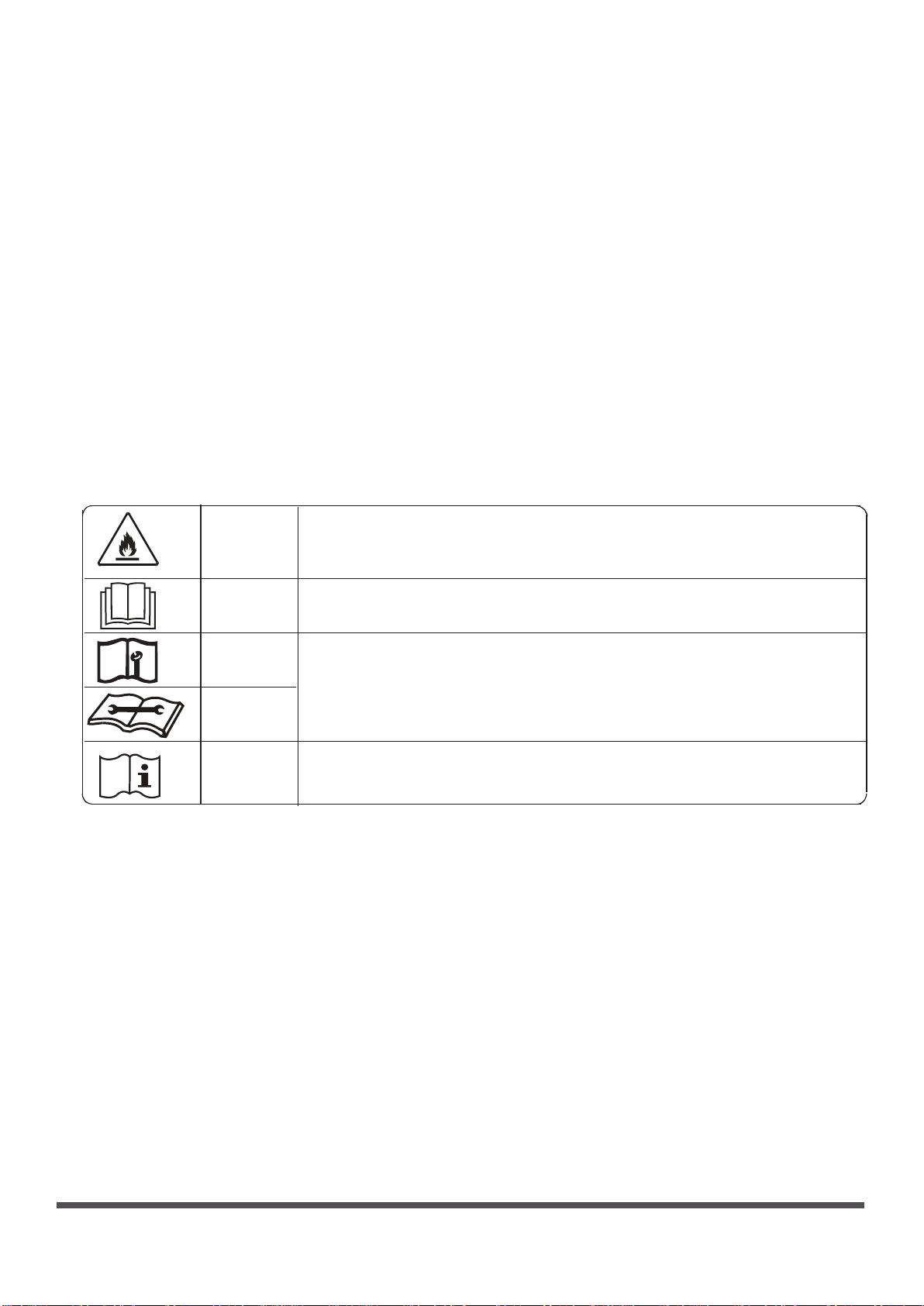
21. Transportation, marking and storage for units
1. Transport of equipment containing flammable refrigerants
Compliance with the transport regulations
2. Marking of equipment using signs
Compliance with local regulations
3. Disposal of equipment using flammable refrigerants
Compliance with national regulations
4. Storage of equipment/appliances
The storage of equipment should be in accordance with the manufacturer’s instructions.
5. Storage of packed (unsold) equipment
Storage package protection should be constructed such that mechanical damage to the
equipment inside the package will not cause a leak of the refrigerant charge.
The maximum number of pieces of equipment permitted to be stored together will be
determined by local regulations.
Explanation of symbols displayed on the indoor unit or outdoor unit
This symbol shows that this appliance used a flammable refrigerant. If the
WARNING
refrigerant is leaked and exposed to an external ignition source, there is
a risk of fire.
CAUTION
CAUTION
CAUTION
CAUTION
This symbol shows that the operation manual should be read carefully.
This symbol shows that a service personnel should be handling this
equipment with reference to the installation manual.
This symbol shows that information is available such as the operating
manual or installation manual.
Page 10

The design and specifications are subject to change without prior notice for
product improvement. Consult with the sales agency or manufacturer for details.
Any updates to the manual will be uploaded to the service website, please check
for the latest version.
SAFETY MANUAL-R32(R290)
16122200002889
20190303
 Loading...