

Page 1

P. 1
- Neo Stormer Quad
USER MANUAL / MANUAL DE USUARIO
PLEASE READ THE INSTRUCTIONS CAREFULLY BEFORE USE
POR FAVOR LEA LAS INSTRUCCIÓNES ANTES DE USAR
NEO STORMER
QUAD
Stage lighting - 1,260 RGBW
high power LEDs
Page 2

P. 2
Neo Stormer Quad -
1. OVERVIEW
English version
STORMER QUAD
Stage lighting - 1,260 RGBW high power LEDs
Stormer Quad is, in a nutshell, an equipment with
an uncommon brightness. Powered by 1,260 RGBW
high power LEDs, it delivers an outstanding performance. Useable as strobe or washer, Stormer Quad
is ideal to satisfy the industry most demanding
designs. With a lightweight and compact design, its
case is design to support the most demanding conditions, making it an ideal option for touring.
Source & Optics
• Light source: 630 RGB 1W LEDs, 630 W 0.3W
LEDs
• LEDs life: 50,000 hours
• Beam angle: 140º
Photometric data
• Luminous ux: 38,000 Lux
Effects & Functions
• 2-in-1: Blinder + Flooder
• High-power
• Optimized refrigeration system
• 3-in-1 LED technology: Smooth RGB mix with no
multi-colored shadows
• Dimmer: 0-100% - 16-bit
• Strobe eect: 0-30Hz
• Refresh rate: 7000Hz
• Intense built-in strobe programs + random
strobe
• Flash duration can be set from 0-650ms in DMX
mode
Control
• DMX Channels: 1/3/4/7/8/16
• Operational modes: DMX, Master/Slave, Autorun & Static colors
Electrical
• Input voltage range: AC100–240V, 50-60Hz
• Power consumption: 800W
Physical
• IP Rating: IP20
• LCD display
• DMX connectors: 4 XLR connectors (XLR-3/
XLR-5 input and output)
• PowerCON™ IN/OUT power supply connectors
• Dimensions: 490x285x120 mm. / 19.3x11.2x4.7
in.
• Weight: 9.35 Kg. / 20.6 Lbs.
Page 3

P. 3
- Neo Stormer Quad
English version
2. GETTING STARTED
Unpacking
• 1 x Stormer Quad RGBW LED Strobe
• 1 x Base Plate
• A Sweet Safety Cable, An Eyebolt & Set of
Mounting Brackets
• An Ever-So-Handy Power Cord
• This Lovely User Manual
Carefully
Check the shipping carton for damage that may
have occurred during shipping. If the carton appears to be damaged, carefully inspect your unit
for damage and be sure all accessories necessary
to operate the unit have arrived intact. In the
event damage has been found or parts are missing, please contact our customer support team for
further instructions. Please do not return this unit
to your dealer without rst contacting customer
support at the number listed below.
Introduction
Congratulations, you have just purchased one of
the most innovative
and reliable lighting xtures on the market today!
Please read and understand the instructions in this
manual carefully and thoroughly before attempting
to operate this unit, This manual contains important information regarding safety protocol that
must be strictly adhered to at all times.
Powering Up
All xtures must be powered directly o a switched
circuit and cannot be run o a rheostat (variable
resistor) or dimmer circuit, even if the rheostat or
dimmer channel is used solely for a 0% to 100% switch.
AC Voltage Switch Not all xtures have a voltage
select switch, so please verify that the xture you
receive is suitable for your local power supply.
See the label on the xture or refer to the xture’s specications chart for more information. A
xture’s listed current rating is its average current
draw under normal conditions. Check the xture
or device carefully to make sure that if a voltage
selection switch exists that it is set to the correct
line voltage you will use.
Warning! Verify that the voltage select switch on
your unit matches the line voltage applied. Damage
to your xture may result if the line voltage applied
does not match the voltage indicated on the volt-
age selector switch. All xtures must be connected
to circuits with a suitable Ground (Earthing).
Getting A Hold Of Us
If something is wrong, please contact your dealer.
Disclaimer: The information and specications
contained in this document are subject to change
without notice. We assumes no responsibility
or liability for any errors or omissions that may
appear in this user manual. We reserves the right
to update the existing document or to create a
new document to correct any errors or omissions
at any time. You can get the latest version of this
document from your dealer.
Safety instructions
Please read these instructions
carefully they include the important
information about the installation
usage and maintenance of this
products.
Page 4

P. 4
Neo Stormer Quad -
English version
Please note: Certain people with epilepsy and
photosensitivity may suer a seizure if exposed to
ashing or strobe lighting. If strobe lighting is to
be used in a production, warnings should be posted
at the front of house or entrance doors to the theater as well as in a program, if distributed.
Example: “WARNING: Strobe lights are used during
this performance.”
• Please keep this User Guide for future use. If
you sell the unit to someone else, be
• sure that they also receive this User Guide.
• Always make sure that you are connecting to
the proper voltage, and that the
• line voltage you are connecting to is not higher
than that stated on the decal or rear
• panel of the xture.
• Make sure there are no ammable materials
close to the unit while operating.
• The unit must be installed in a location with
adequate ventilation, at least 20in
• (50cm) from adjacent surfaces. Be sure that no
ventilation slots are blocked.
• Always disconnect from the power source before servicing or replacing fuse and
• be sure to replace with same fuse size and type.
• Always secure xture using a safety chain.
NEVER carry the xture by its cord. Use its carrying handles.
• Do not operate at ambient temperatures higher than 104°F (40°C).
• In the event of a serious operating problem,
stop using the unit immediately. Never try to
repair the unit by yourself. Repairs carried
out by unskilled people can lead to damage
or malfunction. Please contact the nearest
authorized technical assistance center. Always
use the same type spare parts.
• Never connect the device to a dimmer pack.
• Make sure the power cord is never crimped or
damaged.
• Never disconnect the power cord by pulling or
tugging on the cord.
• Avoid direct eye exposure to the light source
while it is on.
Caution! There are no user serviceable parts inside the unit. Do not open the housing or attempt
any repairs yourself. In the unlikely event your
unit may require service, please call your dealer.
Page 5

P. 5
- Neo Stormer Quad
3. MEET STORMER QUAD RGBW LED STROBE FIXTURE
English version
Main features
• Super bright output via 1260 0.8w RGBW LEDs
• Intense built-in strobe programs + random
strobe
• 2-segment pixel modes can safely be used as
wash (max 40% brightness)
• Built-in over heat protection temperature sen-
sor to extend the lamp life
• Variable electronic strobe & 16-bit dimmer
• User adjustable ash rate of 0-30 ashes per
second
• Flash duration can be set from 0-650ms in
DMX mode
• 7000Hz LED scan rate
• 4-button easy to use LCD control panel menu
• Aluminum mounting bracket with locking
knobs + base plate
• 3-pin & 5-pin DMX Input/Output
• PowerCon™ compatible AC power In/Out
connectors
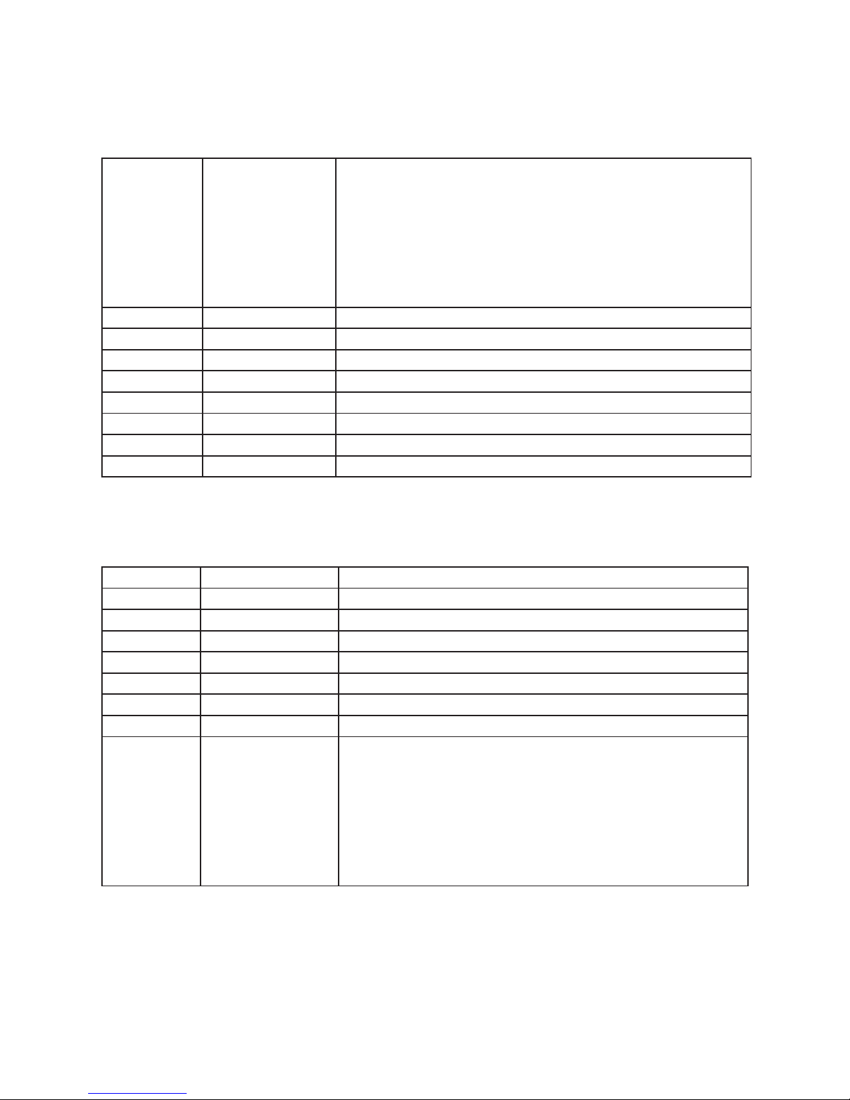
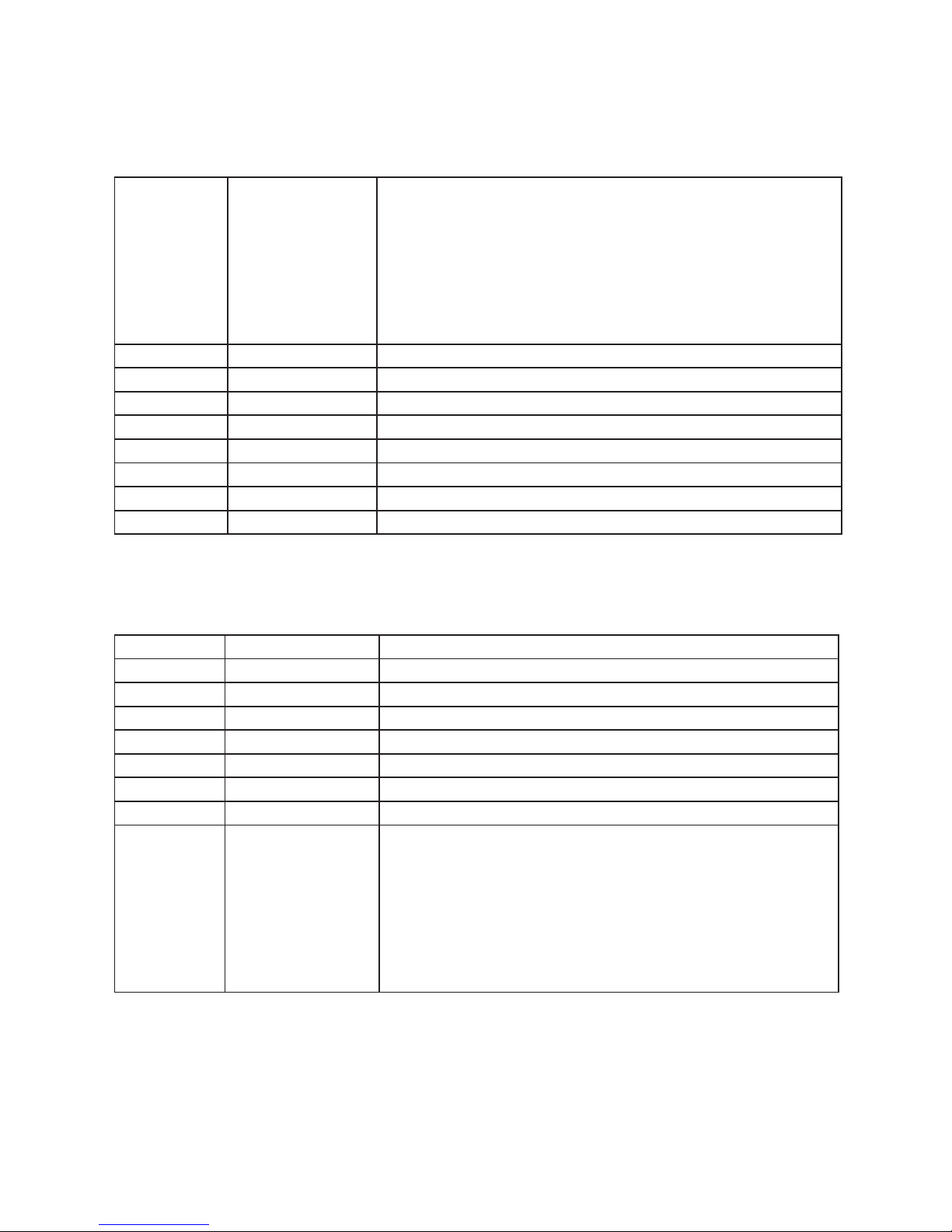
DMX Quick Reference (1/3/4/7/8/16-Channel Modes)
Channel Mode Function
1 3 4 7 8 16
1 1 1 1 1 Master Dimmer (0-100%)
----- ----- ----- 2 2 2 Red segment Intensity (0-100%)
----- ----- ----- 3 3 3 Green segment Intensity (0-100%)
----- ----- ----- 4 4 4 Blue segment Intensity (0-100%)
----- ----- ----- 5 5 5 Write segment Intensity(0-100%)
----- 2 2 6 6 6 Flash duration (0-full on)
1 3 3 7 7 7 Strobe rate (0-30Hz)
----- ----- 4 ----- 8 8 Built-In Eects
----- ----- ----- ----- ----- 9 Red1/Segment 1 Intensity (0-100%)
----- ----- ----- ----- ----- 10 Green1/Segment 2 Intensity (0-100%)
----- ----- ----- ----- ----- 11 Blue1/Segment 3 Intensity (0-100%)
----- ----- ----- ----- ----- 12 Write1/Segment 4 Intensity (0-100%)
----- ----- ----- ----- ----- 13 Red2/Segment 5 Intensity (0-100%)
----- ----- ----- ----- ----- 14 Green2/Segment 6 Intensity (0-100%)
----- ----- ----- ----- ----- 15 Blue2/Segment 7 Intensity (0-100%)
----- ----- ----- ----- ----- 16 Write2/Segment 8 Intensity (0-100%)
Page 6

P. 6
Neo Stormer Quad -
English version
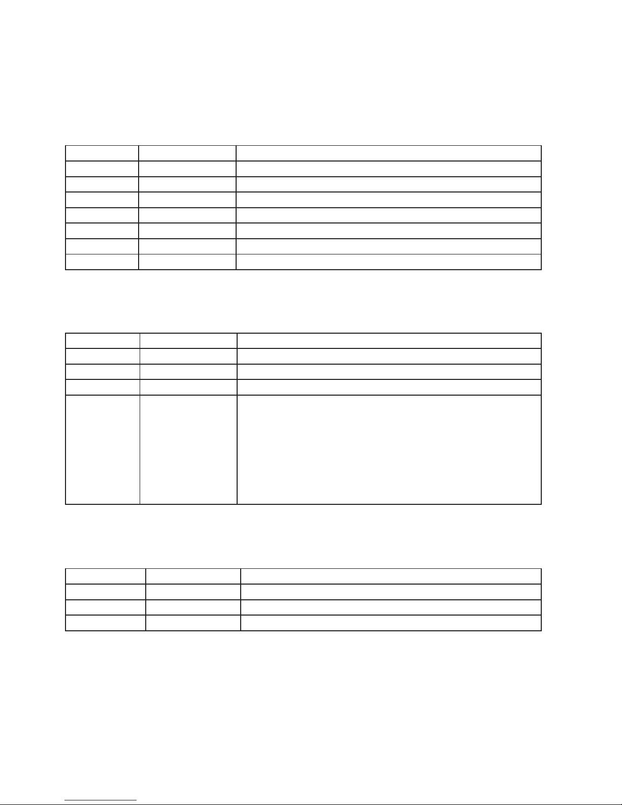
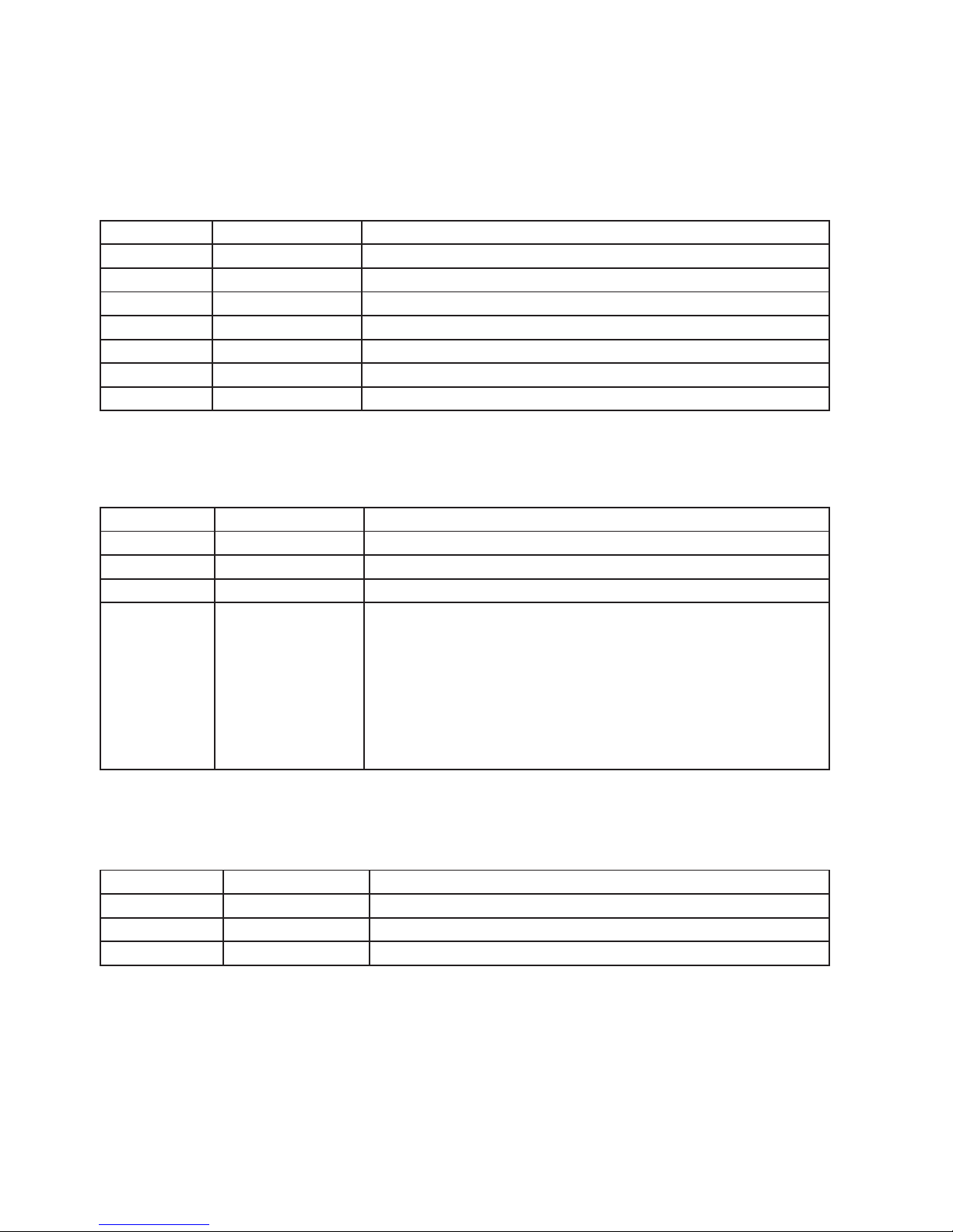
DMX Quick Reference (4/8-Channel: Pixel Modes)
4-Channel Pixel Mode 8-Channel Pixel Mode
1 Red Segment Intensity (0-100%) Red1 Intensity (0-100%)
2 Green Segment Intensity (0-100%) Green1 Intensity (0-100%)
3 Blue Segment Intensity (0-100%) Blue1 Intensity (0-100%)
4 White Segment Intensity (0-100%) White1 Intensity (0-100%)
5 - Red2 Intensity (0-100%)
6 - Green2 Intensity (0-100%)
7 - Blue2 Intensity (0-100%)
8 - White2 Intensity (0-100%)
Page 7

P. 7
- Neo Stormer Quad
English version
4. SETUP
Fuse Replacement
CAUTION! The Stormer Quad utilizes a high-output
switch-mode power supply with an internal use.
Under normal operating conditions, the fuse should
not require replacement. The fuse is eld replaceable, however it is an advanced procedure suited
to qualied individuals. Should your Stormer Quad
fuse require replacement, please contact your dealer for instructions.
Connecting A Bunch of Stormer Quad Fixtures
Follow the guide below to properly link xtures.
Power the rst xture in the chain with a standard
cable (provided with xture). Then jump each subsequent xture with a properly rated jumper cable.
Warning: do not power link more than (2) xtures
in one single chain, electricaloverload may occur.
Data/DMX Cabling
To link xtures together you’ll need data cables.
You should use data grade cables that can carry a
high quality signal and are less prone to electro-
magnetic interference. For instance, Belden© 9841
meets the specications for EIA RS-485 applications. Standard microphone cables will “probably”
be OK, but note that they cannot transmit DMX data
as reliably over long distances. In any event, the
cable should have the following characteristics:
• 2-conductor twisted pair plus a shield
• Maximum capacitance between conductors –
30 pF/.
• Maximum capacitance between conductor &
shield – 55 pF/.
• Maximum resistance of 20 ohms / 1000 .
• Nominal impedance 100 – 140 ohms
Cable Connectors
Cables must have a male XLR connector on one
end and a female XLR connector on the other end.
A Word on Termination: DMX is a resilient communication protocol, however errors still occasionally occur. Termination reduces signal errors, and
therefore best practices include use of terminator
in all circumstances. If you experiencing problems
with erratic xture behavior, especially over long
cable runs, a terminator may help improve performance.
To build your own DMX Terminator:
Obtain a 120-ohm, 1/4-watt resistor, and wire it
between pins 2 & 3 of the last xture. They are
also readily available from specialty retailers.
Caution: Do not allow contact between the com-
mon and the xture’s chassis ground. Grounding
the common can cause a ground loop, and your
xture may perform erratically. Test cables with
an ohm meter to verify correct polarity and to
make sure the pins are not grounded or shorted
to the shield or each other.
Before replacing a fuse, disconnect
power cord, Always replace with the
same type and rating of fuse
Page 8

P. 8
Neo Stormer Quad -
English version
3-Pin / 5-Pin
If you use a controller with a 5 pin DMX output connector, you will need to use a 5 pin to 3 pin adapter.
They are widely available over the internet and from specialty retailers If you’d like to build your own,
the chart below details a proper cable conversion:
Conductor 3-Pin Female (Output) 5-Pin Male (Input)
Ground/Shield Pin 1 Pin 1
DMX Data (-) Pin 2 Pin 2
DMX Data (+) Pin 3 Pin 3
Not Used. No Connection. No Connection
Not Used. No Connection No Connection
Take It To The Next Level: Setting Up
DMX Control
Step 1: Connect the male connector of the DMX
cable to the female connector (output) on the controller.
Step 2: Connect the female connector of the DMX
cable to the rst xture’s male connector (input).
Note: It doesn’t matter which xture address is the
rst one connected. We recommend connecting the
xtures in terms of their proximity to the controller,
rather than connecting the lowest xture number
rst, and so on.
Step 3: Connect other xtures in the chain from
output to input as above. Place a DMX terminator
on the output of the nal xture to ensure best
communication.
Fixture Linking (Master/Slave Mode)
1. Connect the (male) 3 pin connector side of the
DMX cable to the output (female) 3 pin con-
nector of the rst xture.
2. Connect the end of the cable coming from the
rst xture which will have a (female) 3 pin
connector to the input connector of the next
xture consisting of a (male) 3 pin connector.
Then, proceed to connect from the output
as stated above to the input of the following
xture and so on.
A quick note: Oen, the setup for Master-Slave
and Standalone operation requires that the rst
xture in the chain be initialized for this pur-
pose via either settings in the control panel or
DMX IN
DMX IN
DMX OUT
First Fixture in
Chain
Next Fixture
in Chain
T
o Next Fixture
DMX IN
DMX IN
DMX OUT
First Fixture in
Chain
Next Fixture
in Chain
DMX out
Page 9

P. 9
- Neo Stormer Quad
English version
DIP-switches. Secondarily, the xtures that follow
may also require a slave setting.
Check the “Operating Adjustments” section in this
manual for complete instructions for this type of
setup and conguration.
Mounting & Rigging
This xture can be mounted in any orientation
(vertical, horizontal). Always make sure there is
adequate ventilation and no ammable surfaces
within 2 feet (.6 meters) of the xture. You can
mount the xture using xture clamps or with
threaded bolt type hardware. Always install the
included safety eyebolt and cable when mounting
in overhead or wall locations.
Do not mount the xture in the ventilation path of a nearby heating supply duct.
The heated airow will cause xture failure due to overheating.
Page 10

P. 1 0
Neo Stormer Quad -
English version
5. OPERATING ADJUSTMENTS
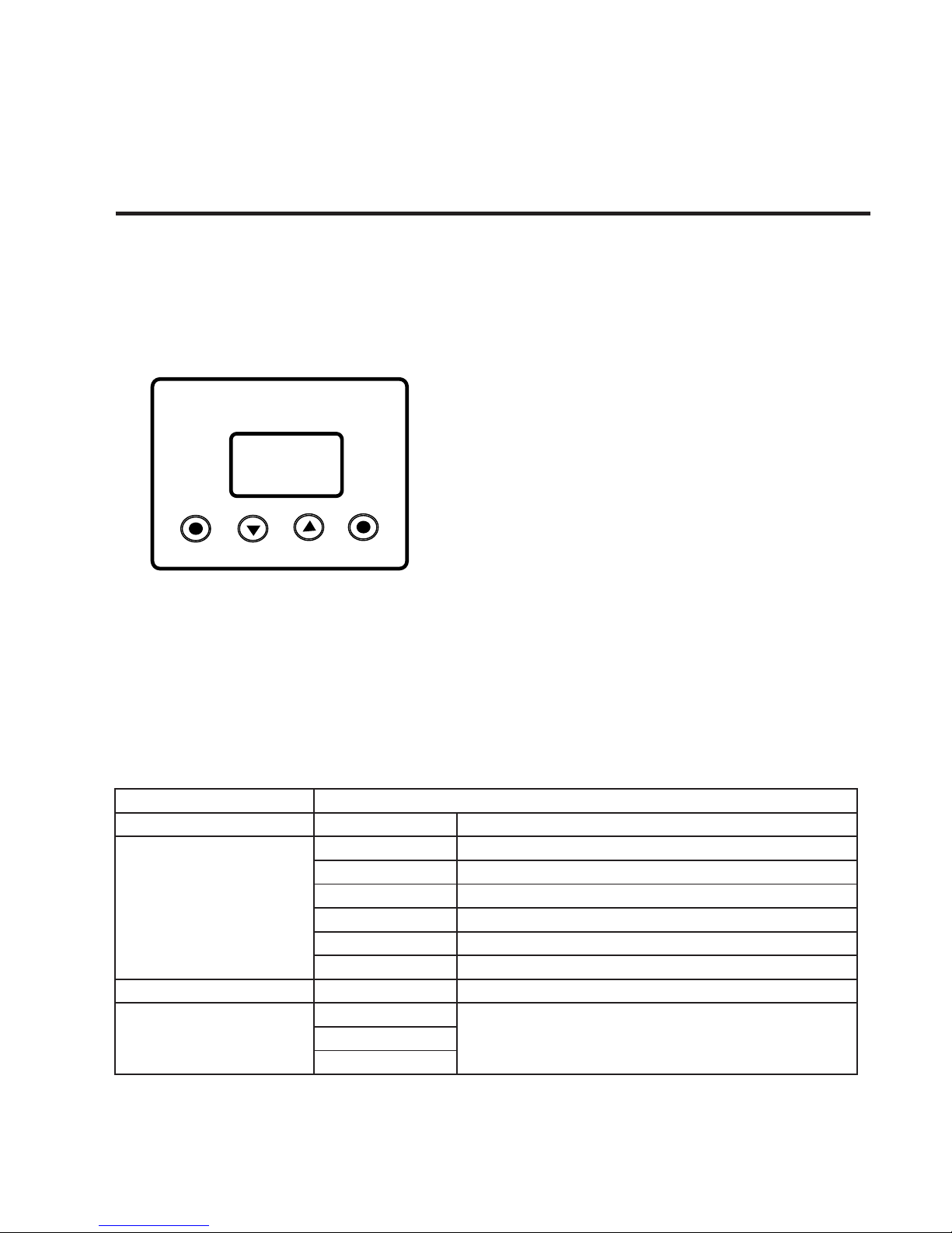
The Control Panel
All the goodies and dierent modes possible with
the Storm1000 RGBW are accessed by using the
control panel on the front of the xture. There are 4
control buttons below the LCD display which allow
you to navigate through the various control panel
menus.
<ESC> Used to access the menu or return to a pre-
vious menu option.
<DOWN> Scrolls through menu options in descending order.
<UP> Scrolls through menu options in ascending
order.
<ENTER> Used to store the current menu or option within a menu.
The LCD control panel display shows the menu
items you select from the menu map on page #10.
When a menu function is selected, the display
will show immediately the rst available option
for the selected menu function. To select a menu
item, press <ENTER>.
To navigate through the LCD control panel, use
the <UP/DOWN> buttons to scroll through the
menu options. Press the <ENTER> button, then
use the <UP/DOWN> buttons to view any submenu options. Press <ESC> to continue without
saving, or press <ENTER> button, then the <ESC>
to save and return to the previous menu item.
LED STROBE
ESC
DOWN
UP
ENTER
The Control Panel Menu Structure
Menu Sub-menu
Address Set DMX Address 001-512
Auto
Mode 1 Auto Mode 1
Mode 2 Auto Mode 2
Mode 3 Auto Mode 3
Mode 4 Auto Mode 4
Mode 5 Auto Mode 5
Mode 6 Auto Mode 6
Speed 000-031 Auto Run Speed
Test LED
All on
All On + Individual LED Segment
Testing
Red on
Green on
Page 11

P. 11
- Neo Stormer Quad
English version
Blue on
White on
Red 1 on
Red 2 on
Green 1 on
Green 2 on
Blue 1 on
Blue 2 on
White 1 on
White 2 on
Fade on
Temp <ENTER> Internal Temperature
Time <ENTER> Total Run Time
Cong
DMX Status
Value Hold
Holds the last DMX values if signal is lost
Value Clear
Clears the DMX values if signal is lost
Display Mode LCD Display ON or Auto OFF
Temp Unit CS Celsius degree and Fahrenheit degree for selection
Channel Mode
Channel 1 (1ch DMX mode)
Channel 3 (1ch DMX mode)
Channel 4 (1ch DMX mode)
Channel 7 (1ch DMX mode)
Channel 8 (1ch DMX mode)
Channel 16 (1ch DMX mode)
Pixel 4 (4ch DMX pixel control)
Pixel 8 (8ch DMX pixel control)
Key Mode
Key Lock
Menu buttons lock aer 30sec of
inactivity (push more than once to temporarily unlock
buttons).
Key Unlock
Menu buttons are not locked.
Load Default Load Default Resets all values to default
Page 12

P. 12
Neo Stormer Quad -
English version
DMX Mode
Allows the unit to be controlled by any universal DMX
controller.
Set the Starting DMX Address:
The default mode for the xture is DMX, so the rst
menu item that you can edit is the starting DMX
address.
1. Press the <UP/DOWN> buttons until you reach
Address.
2. Push the <ENTER> button.
3. Use the <UP/DOWN> buttons to select a channel
from 001-512.
4. Press the <ENTER> button to conrm.
5. Press the <ESC> button to return to the main
menu.
Select the DMX Channel Mode:
1. Press the <UP/DOWN> buttons until you reach
Cong.
2. Push the <ENTER> button.
3. Using the <UP/DOWN> buttons, highlight DMX
Mode, then press <ENTER>.
4. Use the <UP/DOWN> buttons to select 1, 3, 4, 7,
8, 16, or 4/8 pixel modes.
5. Press <ENTER>, and then press the <ESC> button until you reach the Address screen.
Master/Slave Mode:
1. Disconnect xture(s) from any DMX signal
source.
2. Set each xture to matching DMX modes.
3. Connect all xtures together via DMX. The rst
xture in the DMX chain will be the master, followed
by the slave xtures.
4. Connect DMX controller to the master unit for
DMX control.
Load Default Settings:
1. Press the <UP/DOWN> buttons until you reach
Load Default.
2. Push the <ENTER> button.
Auto & Standalone Modes
Allows a single or Master/Slaved units to run factory
installed programs at user selectable speeds.
Auto Mode:
1. Press the <UP/DOWN> buttons until you reach
Auto.
2. Push the <ENTER> button.
3. Use the <UP/DOWN> buttons to select from
Mode 1 to Mode 6.
4. Press the <ENTER> button to conrm.
Auto Program Speed:
1. Press the <UP/DOWN> buttons until you reach
Speed.
2. Push the <ENTER> button.
3. Use the <UP/DOWN> buttons to select from
000-031.
4. Press the <ENTER> button to conrm.
Additional Features
Never thought you would ever see so many niy
neato features in a strobe light did you?
Temperature:
IMPORTANT - Brightness will decrease when the
LED temperature rises over 55ºC. If a temperature of +70ºC is reached, the overheat protection
sensor will activate, initiating blackout until a safe
temperature is reached. It’s highly recommended
to not use the LEDs at full strobe brightness for
longer than a 1 minute period. You can safely use
the xture as a normal wash in 4/8 pixel modes
which are programmed to achieve a max of 40%
strobe brightness.
1. Press the <UP/DOWN> buttons until you reach
Temp.
2. Push the <ENTER> button.
3. The display will show the current temperature
in Celsius degrees.
Signal Loss Settings:
In the event of DMX signal loss, you can set the x-
Page 13

P. 13
- Neo Stormer Quad
English version
ture to either hold its last received DMX signal values,
or clear them.
1. Press the <UP/DOWN> buttons until you reach
Cong.
2. Push the <ENTER> button.
3. Using the <UP/DOWN> buttons, navigate to DMX
Status, then press the <ENTER> button.
4. Use the <UP/DOWN> buttons to select either
Value Hold, or Value Clear.
5. Press the <ENTER> button to conrm.
LCD Display On/Auto O:
Display mode On will keep the LCD illuminated con-
tinually, Auto will shut the display o aer 30 seconds
of inactivity.
1. Press the <UP/DOWN> buttons until you reach
Cong.
2. Push the <ENTER> button, and navigate to Display Mode.
3. Push the <ENTER> button, then select either On
or Auto, and press the <ENTER> button.
Key (Button) Protection Mode:
With Key Lock active, buttons will be unresponsive to
any initial button press aer 30 seconds of inactivity.
Temporary unlock will occur with more than 1 button
press. To disable this feature, activate Key Unlock.
1. Press the <UP/DOWN> buttons until you reach
Cong.
2. Push the <ENTER> button.
3. Press the <UP/DOWN> buttons until you reach
Key Mode, then press<ENTER>.
4. Use the <UP/DOWN> buttons to select either
Key Lock, or Key Unlock, and press the <ENTER>
button.
Temp Unit CS
1. Press the <UP/DOWN> buttons until you reach
Cong.
2. Push the <ENTER> button, and navigate to
Temp Unit CS
3. Using the <UP/DOWN> buttons to select Celsius degree or Fahrenheit degree
Test Mode:
1. Press the <UP/DOWN> buttons until you reach
Test LED.
2. Push the <ENTER> button.
3. Now, you can choose to test all of the LEDs at
once, or individually test each of its 9 segments.
Use the <UP/DOWN> buttons to navigate, and
press the <ENTER> to conrm.
DMX Values In-Depth (16-Channel Mode)
Ch. Value Function
1 000 <--> 255 Master Dimmer (0-100%)
2 000 <--> 255 Red segment Intensity (0-100%)
3 000 <--> 255 Green segment Intensity (0-100%)
4 000 <--> 255 Blue segment Intensity (0-100%)
5 000 <--> 255 Write segment Intensity(0-100%)
6 000 <--> 255 Flash duration (0-full on)
7 000 <--> 255 Strobe rate (0-30Hz)
Page 14
P. 14
Neo Stormer Quad -
English version
8
000 <--> 005
006 <--> 042
043 <--> 085
086 <--> 128
129 <--> 171
172 <--> 214
215 <--> 255
Built-In Programs
No function
Ramp up eect (slow <--> fast)
Ramp down eect (slow <--> fast)
Ramp up-down eect (slow <--> fast)
Random eect (slow <--> fast)
Lightning eect (slow <--> fast)
Spike eect
9 000 <--> 255 Red1/Segment 1 Intensity (0-100%)
10 000 <--> 255 Green1/Segment 2 Intensity (0-100%)
11 000 <--> 255 Blue1/Segment 3 Intensity (0-100%)
12 000 <--> 255 Write1/Segment 4 Intensity (0-100%)
13 000 <--> 255 Red2/Segment 5 Intensity (0-100%)
14 000 <--> 255 Green2/Segment 6 Intensity (0-100%)
15 000 <--> 255 Blue2/Segment 7 Intensity (0-100%)
16 000 <--> 255 Write2/Segment 8 Intensity (0-100%)
DMX Values In-Depth (8-Channel Mode)
Ch. Value Function
1 000 <--> 255 Master Dimmer (0-100%)
2 000 <--> 255 Red segment Intensity (0-100%)
3 000 <--> 255 Green segment Intensity (0-100%)
4 000 <--> 255 Blue segment Intensity (0-100%)
5 000 <--> 255 Write segment Intensity(0-100%)
6 000 <--> 255 Flash duration (0-full on)
7 000 <--> 255 Strobe rate (0-30Hz)
8
000 <--> 005
006 <--> 042
043 <--> 085
086 <--> 128
129 <--> 171
172 <--> 214
215 <--> 255
Built-In Programs
No function
Ramp up eect (slow <--> fast)
Ramp down eect (slow <--> fast)
Ramp up-down eect (slow <--> fast)
Random eect (slow <--> fast)
Lightning eect (slow <--> fast)
Spike eect
Page 15
P. 15
- Neo Stormer Quad
Versión Español
DMX Values In-Depth (7-Channel Mode)
DMX Values In-Depth (4-Channel Mode)
DMX Values In-Depth (3-Channel Mode)
Ch. Value Function
1 000 <--> 255 Master Dimmer (0-100%)
2 000 <--> 255 Red segment Intensity (0-100%)
3 000 <--> 255 Green segment Intensity (0-100%)
4 000 <--> 255 Blue segment Intensity (0-100%)
5 000 <--> 255 Write segment Intensity(0-100%)
6 000 <--> 255 Flash duration (0-full on)
7 000 <--> 255 Strobe rate (0-30Hz)
Ch. Value Function
1 000 <--> 255 Dimmer (0% <--> 100%)
2 000 <--> 255 Flash Duration (0% <--> 100%)
3 000 <--> 255 Strobe Rate (0-30Hz)
4
000 <--> 005
006 <--> 042
043 <--> 085
086 <--> 128
129 <--> 171
172 <--> 214
215 <--> 255
Built-In Programs
No function
Ramp up eect (slow <--> fast)
Ramp down eect (slow <--> fast)
Ramp up-down eect (slow <--> fast)
Random eect (slow <--> fast)
Lightning eect (slow <--> fast)
Spike eect
Ch. Value Function
1 000 <--> 255 Dimmer (0% <--> 100%)
2 000 <--> 255 Flash Duration (0% <--> 100%)
3 000 <--> 255 Strobe Rate (0-30Hz)
Page 16

P. 1 6
Neo Stormer Quad -
Versión Español
DMX Values In-Depth (1-Channel Mode)
Ch. Value Function
1 000 <--> 255 Dimmer (0% <--> 100%)
DMX Values In-Depth (4-Channel Pixel Mode)
DMX Values In-Depth (8-Channel Pixel Mode)
Ch. Value Function
1
000 <--> 021
022 <--> 255
No Function
Red/Segment Intensity (0% <--> 100%)
2
000 <--> 021
022 <--> 255
No Function
Green/Segment Intensity (0% <--> 100%)
3
000 <--> 021
022 <--> 255
No Function
Blue/Segment Intensity (0% <--> 100%)
4
000 <--> 021
022 <--> 255
No Function
White/Segment Intensity (0% <--> 100%)
Ch. Value Function
1
000 <--> 021
022 <--> 255
No Function
Red/Segment 1 Intensity (0% <--> 100%)
2
000 <--> 021
022 <--> 255
No Function
Green/Segment 1 Intensity (0% <--> 100%)
3
000 <--> 021
022 <--> 255
No Function
Blue/Segment 1 Intensity (0% <--> 100%)
4
000 <--> 021
022 <--> 255
No Function
White/Segment 1 Intensity (0% <--> 100%)
5
000 <--> 021
022 <--> 255
No Function
Red/Segment 2 Intensity (0% <--> 100%)
6
000 <--> 021
022 <--> 255
No Function
Green/Segment 2 Intensity (0% <--> 100%)
7
000 <--> 021
022 <--> 255
No Function
Blue/Segment 2 Intensity (0% <--> 100%)
8
000 <--> 021
022 <--> 255
No Function
White/Segment 2 Intensity (0% <--> 100%)
Page 17

P. 17
- Neo Stormer Quad
Versión Español
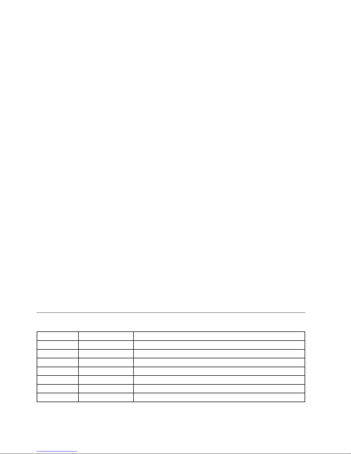
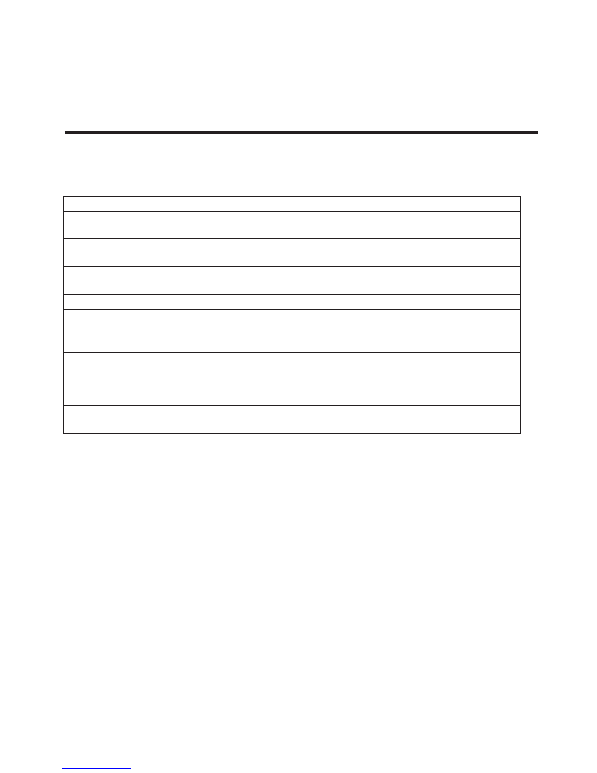
Troubleshooting
Maintenance
Symptom Solution
Fixture AutoShut O
If it is stopped or dimmer than normal, the unit may have shut itself o due to
high heat. This is to protect the xture from overheating.
No Light Output Check to ensure xture is operating under.
No Light Output Check to ensure xture is operating under correct mode, IE sound active/auto/
DMX/Etc., if applicable.
Chase Speed
Too Fast/Slow
Check to ensure proper setup of speed adjustment.
No Power Check fuse, AC cord and circuit for malfunction.
Blown Fuse Check AC cord and circuit for damage, verify that moving parts are not restricted
and that unit’s ventilation is not obstructed.
Slow Movement Check that speed channels are set appropriately.
Fixture Not
Responding /
Responding Erratically
Make sure all connectors are seated properly and securely.
Use Only DMX Cables and/or check cables for defects.
Install a Terminator.
Reset xture(s).
Fixture Moving
On Its Own
Verify proper mode of operation. Is the xture in “Auto” mode?
6. TROUBLESHOOTING AND MAINTENANCE
• Your xture will require regular cleaning to
prevent a build up of dust and smoke debris
on the optics and housing. Aer disconnection
of power, wipe down the xture with a damp
cloth. Never use alcohol or solvents as this may
damage the nish. Use glass cleaner for glass
surfaces such as external lens or mirrors. A
dry paint brush is an excellent tool to remove
surface dust.
• Be sure to periodically check for loose parts
that could damage the xture or potentially
allow the xture to cause injury. Make sure all
overhead and wall installations have a secondary safety device installed such as a safety ca-
ble rated for your xture type and size. Check
the power cord as well, make sure there is no
damage that could cause electrical shock,
never remove the ground prong.
• There are no user-servicable parts in this
xture. Do not attempt to open and repair this
xture. Return to the factory for repair.
Always disconnect power before
cleaning never remove the ground
prong from power cord never spin
a fan with compressed air, this can
damage components in your xture.
Page 18

P. 18
Neo Stormer Quad -
Versión Español
1. DESCRIPCIÓN
STORMER QUAD
Equipo con 1,260 LEDs RGBW de alta potencia
Stormer Quad es, en pocas palabras, un equipo
con un brillo fuera de lo común. Con 1,260 LEDs
RGBW de alta potencia, brinda un rendimiento de
los más destacados a nivel mundial. Utilizable como
estrobo (blinder) o bañador, Stormer Quad es ideal
para satisfacer los diseños más exigentes de nuestra
industria. De diseño liviano y compacto, su recinto
está pensado para soportar las condiciones más de-
mandantes, siendo ideal para las extensas jornadas
del touring.
Fuente & Ópticas
• Fuente de luz: 630 LEDs RGB de 1W, 630 LEDs W
de 0.3W
• Vida útil promedio: 50.000 horas
• Ángulo de haz: 140º
Datos fotométricos
• Flujo lumínico: 38,000 Lux
Efectos y funciones
• 2-en-1: Blinder + bañador profesional
• Alta potencia
• Sistema de refrigeración optimizado
• Tecnología LED 3-en-1: Mezcla de color RGB sin
sombras multicolores
• Dimmer: 0-100% de 16-bits
• Efecto estrobo: 0-30Hz
• Frecuencia de refresco: 7000Hz
• Función de estrobo random + Intensos programas incorporados
• La duración del ash se puede establecer de
0-650ms en su modo DMX
Control
• Canales DMX: 1/3/4/7/8/16
• Modos de operación: DMX, Maestro/esclavo,
Automático & Estático
Eléctrico
• Rango de voltaje de entrada: AC100–240V,
50-60Hz
• Consumo de potencia: 800W
Físico
• Certicación IP20
• Display LCD
• Conectores DMX: 4 conectores XLR (XLR-3/
XLR-5 entrada y salida)
• Conectores de alimentación de entrada y
salida PowerCON™
• Dimensiones: 490x285x120 mm. /
19.3x11.2x4.7 pulg.
• Peso: 9.35 Kg. / 20.6 Lbs.
Page 19

P. 1 9
- Neo Stormer Quad
Versión Español
2. GUÍA DE INICIO
Contenido
• 1 equipo Stormer Quad LED RGBW.
• 1 placa de base.
• 1 cable de seguridad, 1 armella y 1 set de
soportes de montaje.
• 1 cable de suministro eléctrico.
• 1 Manual del usuario.
Verique
Verique que el equipo no haya sufrido averías
durante el envío. Si observa daños en el embalaje,
examine la unidad y asegúrese de que todos los
accesorios necesarios para operar la unidad hayan
sido entregados en buen estado.
En caso de que encuentre daños o piezas faltantes,
póngase en contacto de inmediato con su distribuidor. No devuelva el equipo a su distribuidor
sin haberse comunicado antes con asistencia al
cliente.
Introducción
Gracias por haber elegido el producto Stormer
Quad. Usted ha adquirido uno de los equipos más
conables e innovadores del mercado actual. Procure familiarizarse con las instrucciones y advertencias de seguridad antes de utilizar el equipo. El
presente manual contiene información de importancia sobre el protocolo de seguridad. Procure
seguirlo en todo momento.
Suministro eléctrico
Todas los equipos deben conectarse directamente
a un circuito conmutado. Nunca conecte esta unidad a un reóstato o circuito de atenuación, incluso
si se utiliza exclusivamente para una conmutación
de 0-100%.
Rango de voltaje de entrada No todos los equipos cuentan con un selector de voltaje incorporado. Compruebe que el voltaje utilizado no sea
superior ni inferior a los valores indicados en el
presente manual o en la etiqueta del cable de
alimentación. La capacidad de corriente de un
equipo corresponde al consumo de corriente en
condiciones normales. En caso de que el equipo
disponga de un selector del voltaje, verique que
esté en el rango correcto.
Advertencia! Evite daños de tensión eléctrica.
Verique que el selector de voltaje de su equipo coincida con los valores aplicados. Todos los equipos
deben contar con conexión a tierra.
Contacto
En caso de que algo falle, póngase en contacto con
su distribuidor.
Observación Toda las especicaciones descritas
en este manual están sujetas a cambios sin previo
aviso. El proveedor no asumirá responsabilidad
por los errores u omisiones del manual. Asimismo
se reserva el derecho de actualizar el documento
y/o crear uno nuevo para corregir errores u omisiones en cualquier momento. El usuario puede
descargar la última versión del presente manual
desde la página web de Ampro.
Instrucciones de seguridad
Procure leer las instrucciones
y advertencias de seguridad
del manual para garantizar el
buen estado del equipo y su
funcionamiento seguro.
Page 20

P. 2 0
Neo Stormer Quad -
Versión Español
Advertencia: La luz con efecto estrobo o ash
puede generar convulsiones en las personas
fotosensitivas o con epilepsia. En caso de utilizar
dichos efectos en grandes eventos, se recomienda
la colocación de advertencias en la entrada o en los
programas (en caso de que los hubiera). Por ejem-
plo: “Advertencia. Durante el show se utilizan luces
con efecto estrobo”.
• Conserve el presente manual para futuras referencias. En caso de vender la unidad, procure
entregar esta guía al comprador.
• Utilice el equipo únicamente con la corriente
alterna indicada en las especicaciones técnicas. Compruebe que el voltaje utilizado no sea
superior ni inferior.
• Mantenga el equipo alejado de supercies
inamables durante su funcionamiento.
• Instale el equipo en una zona con ventilación
y a una distancia de, al menos, 50cm (20in)
de otros objetos. Asegúrese de no obstruir las
ranuras de ventilación.
• Siempre desconecte el equipo del suministro
eléctrico antes de realizar alguna tarea de mantenimiento o de reemplazar el fusible (utilice
siempre un repuesto del mismo tipo y tamaño).
• Disponga de un cable de seguridad para jar
el equipo al punto de instalación. Para trasladar la unidad, tómela de las manijas, nunca
del cable de alimentación.
• No utilice el equipo si la temperatura ambiente supera los 40°C (104°F).
• En caso de que exista un problema serio de
funcionamiento, deje de utilizar la unidad
inmediatamente. Si el equipo precisa reparación, pónganse en contacto con el servicio
técnico autorizado. Las reparaciones realiza-
das por personas inexpertas pueden causar
daños irreparables en el equipo.
• No conecte el equipo a un dimmer.
• Verique que el cable de suministro eléctrico
no se encuentre cortado o dañado.
• Nunca tire del cable para desconectar el
equipo.
• No mire de forma directa a la fuente de luz
cuando el equipo esté encendido.
¡Advertencia! Evite desarmar el equipo. En su
interior no hay piezas que puedan ser reparadas
por el usuario. En caso de que el equipo precise
reparación, póngase en contacto con el servicio
técnico autorizado.
Page 21

P. 2 1
- Neo Stormer Quad
Versión Español
3.DESCRIPCIÓN DEL EQUIPO
Características principales
• Fuente de luz: 1260 LEDs RGBW de 0.8w.
• Intensos programas incorporados de estrobo +
estrobo aleatorio.
• Modos de pixel de dos segmentos permiten que
se use como bañador (brillo máximo 40%).
• Sensor de temperatura incorporado para prevenir sobrecalentamiento y prolongar la vida
útil de la lámpara.
• Estrobo electrónico variable y dimmer de 16
bits.
• Velocidad de ash regulable de 0-30 ashes por
segundo.
• Duración de ash regulable de 0-650ms en
modo DMX.
• Frecuencia de refresco: 7000Hz.
• Panel de control de 4 botones con pantalla
LCD de fácil manejo.
• Soportes de montaje con perillas de jación +
placa de base.
• Conectores DMX de 3/5 pines (de entrada y
salida).
• Conectores de alimentación PowerCon™ (de
entrada y salida).
Referencia rápida de canales DMX (Modos 1/3/4/7/8/16 canales)
Canal Función
1 3 4 7 8 16
1 1 1 1 1 Dimmer maestro (0-100%)
----- ----- ----- 2 2 2 Intensidad de segmento rojo (0-100%)
----- ----- ----- 3 3 3 Intensidad de segmento verde (0-100%)
----- ----- ----- 4 4 4 Intensidad de segmento azul (0-100%)
----- ----- ----- 5 5 5 Intensidad de segmento blanco (0-100%)
----- 2 2 6 6 6 Duración de ash (0-full)
1 3 3 7 7 7 Rango de estrobo (0-30 Hz)
----- ----- 4 ----- 8 8 Efectos incorporados
----- ----- ----- ----- ----- 9 Rojo 1/Intensidad de segmento 1 (0-100%)
----- ----- ----- ----- ----- 10 Verde 1/Intensidad de segmento 2 (0-100%)
----- ----- ----- ----- ----- 11 Azul 1/Intensidad de segmento 3 (0-100%)
----- ----- ----- ----- ----- 12 Blanco 1/Intensidad de segmento 4 (0-100%)
----- ----- ----- ----- ----- 13 Rojo 2/Intensidad de segmento 5 (0-100%)
----- ----- ----- ----- ----- 14 Verde 2/Intensidad de segmento 6 (0-100%)
----- ----- ----- ----- ----- 15 Azul 2/Intensidad de segmento 7 (0-100%)
----- ----- ----- ----- ----- 16 Blanco 2/Intensidad de segmento 8 (0-100%)
Page 22

P. 2 2
Neo Stormer Quad -
Versión Español
Referencia rápida de canales DMX (Modos 4/8 canales: Modo pixel)
4 canales: Modo pixel 8 canales: Modo pixel
1 Intensidad de segmento rojo (0-100%) Intensidad de rojo 1 (0-100%)
2 Intensidad de segmento verde (0-100%) Intensidad de verde 1 (0-100%)
3 Intensidad de segmento azul (0-100%) Intensidad de azul 1 (0-100%)
4 Intensidad de segmento blanco (0-100%) Intensidad de blanco 1 (0-100%)
5 - Intensidad de rojo 2 (0-100%)
6 - Intensidad de verde 2 (0-100%)
7 - Intensidad de azul 2 (0-100%)
8 - Intensidad de blanco 2 (0-100%)
Page 23

P. 2 3
- Neo Stormer Quad
Versión Español
4. INSTALACIÓN
Sustitución del fusible
PRECAUCIÓN El Stormer Quad cuenta con una
fuente de alimentación conmutada de alta potencia
con un fusible interno. En condiciones normales de
funcionamiento, el fusible no requiere sustitución.
Sin embargo, es recambiable. Solo una persona ca-
licada debe realizar la tarea. Póngase en contacto
con su distribuidor para obtener más información.
Enlace de varios equipos Stormer Quad
Conecte el primer equipo de la cadena con un cable
de alimentación estándar (incluido en la caja). Luego utilice un cable puente apropiado para conectar
el resto de los equipos. Advertencia: No conecte
más de dos equipos en una sola línea para evitar
una posible sobrecarga eléctrica.
Cable de datos DMX
Para enlazar equipos es necesario contar con cables de datos. Utilice cables que puedan trasladar
señal de alta calidad y poco propensos a la interferencia electromagnética. Por ejemplo, el cable
Belden© 9841 cumple con las especicaciones EIA
RS-485. Es posible utilizar cables de micrófono
estándar, pero tenga en cuenta que la transmisión
de datos DMX es menos estable en largos tramos
de cableado. Todo cable debe contar con las
siguientes características:
• 2 conductores trenzados con malla protectora.
• Capacidad máxima entre conductores: -30 pF/
.
• Capacidad máxima entre conductores y malla
protectora: -55 pF/.
• Resistencia máxima: 20 ohm / 1000 .
• Impedancia nominal: 100-140 ohm.
Cableado
El cableado debe contar con un conector XLR
macho de un lado y XLR hembra del otro.
Los nales de línea o terminadores reducen los
errores de señal. Para evitar la interferencia
o el comportamiento anómalo del equipo es
recomendable utilizar un nal de línea DMX. En
especial en cableados que recorren largas distancias.
Crear un terminador DMX:
Coloque una resistencia de 120 ohm y 1/4 W entre
el pin 2 y 3 del último equipo de la cadena.
Precaución: No permita el contacto entre el suelo
del chasis común y el del aparato. Poner a tierra
lo común puede causar un bucle de tierra, y su
dispositivo puede funcionar de manera errática.
Pruebe los cables con un medidor de ohmios para
vericar la polaridad correcta y para asegurarse
de que los pines no estén conectado a tierra o en
cortocircuito al escudo o el uno al otro.
Desconecte el equipo antes de
colocar el fusible. Siempre utilice un
fusible del mismo tipo y rango.
Page 24

P. 2 4
Neo Stormer Quad -
Versión Español
Conversión de 5 pines a 3 pines
Si utilizar un controlador con salida DMX de 5 pines, va a necesitar un adaptador de 5 pines a 3 pines. En
caso de que preera crear el propio, la tabla a continuación describe la conversión de cables correcta.
Conductor 3 pines hembra (salida) 5 pines macho (entrada)
Tierra/Malla Pin 1 Pin 1
Datos DMX (-) Pin 2 Pin 2
Datos DMX (+) Pin 3 Pin 3
Sin uso Sin uso Sin uso
Sin uso Sin uso Sin uso
Conguración del control vía DMX
1) Conecte el extremo macho del cable DMX a
la salida hembra del controlador.
2) Conecte el extremo hembra del cable DMX a
la entrada macho del primer equipo. Nota:
Conectelos equipos según su proximidad al controlador en lugar de seguir un orden en particular.
3) Conecte el resto de los equipos de la cadena
desde la salida a la entrada como indican los pasos
previos.Utilice un terminador DMX en la salida del
último equipo de la cadena para garantizar la buena comunicación.
Enlace de equipos
(modo maestro/esclavo)
1. Enchufe el conector macho de 3 pines del
cable DMX a la salida hembra de 3 pines del
primer equipo.
2. Enchufe el extremo hembra de 3 pines
proveniente del cable del primer equipo al
conector de entrada macho de 3 pines del
próximo equipo. Luego conecte el resto de
los equipos de la cadena desde la salida a la
entrada del siguiente equipo, como indican
los pasos aquí descritos.
DMX IN
DMX IN
DMX OUT
First Fixture in
Chain
Next Fixture
in Chain
To Next Fixture
DMX IN
DMX IN
DMX OUT
First Fixture in
Chain
Next Fixture
in Chain
DMX out
Primera unidad
de la cadena
Primera unidad de la
cadena
Siguiente
unidad de la
cadena
Siguiente
unidad de la
cadena
A la siguiente unidad
A la siguiente
unidad
Page 25

P. 2 5
- Neo Stormer Quad
Versión Español
Nota: En ocasiones, la conguración del modo
stand alone o maestro/esclavo requiere que el
primer equipo de la cadena se inicie a través de las
opciones del panel de control o con el interruptor
DIP. Es posible que el segundo equipo de la cadena
también requiera estar congurado como esclavo.
Para obtener más instrucciones, reérase a la sección “Instrucciones de uso” del presente manual.
Montaje y Rigging
El equipo permite el montaje en sentido vertical
y horizontal, siempre que el punto de jación disponga de la ventilación necesaria y se encuentre a
un mínimo de 0,6 metros de supercies inamables. Para la instalación en altura siempre utilice los soportes de montaje y el cable de seguridad (incluidos en la caja).
Advertencia: No instale el equipo cerca de la salida de ventilación de un sistema de
calefacción. El ujo de aire causará daños por recalentamiento.
Page 26
P. 2 6
Neo Stormer Quad -
Versión Español
5. INSTRUCCIONES DE USO
Panel de control
Acceda a todos los modos y conguraciones posibles del Storm1000 RGBW a través del panel de
control ubicado en la base del equipo.
<ESC> Acceda al menú deseado o regrese a la pantalla previa.
<DOWN> Desplácese en orden descendente por las
opciones del menú.
<UP> Desplácese en orden ascendente por las
opciones del menú.
<ENTER> Seleccione y ejecute la opción o menú
deseados.
En la pantalla LCD del panel de control visualizará
los ítems del menú seleccionados. Cuando seleccione una función del menú, la pantalla mostrará
inmediatamente la primera opción disponible.
Para ingresar en la opción deseada, presione
<ENTER>.
Utilice las teclas <UP/DOWN> para desplazarse
por las opciones del menú. Luego presione
<ENTER> y utilice nuevamente <UP/DOWN> para
visualizar las opciones de los submenús.
Presione <ESC> para continuar navegando sin
guardar cambios o <ENTER> seguido de <ESC>
para guardar cambios y regresar al ítem del menú
anterior.
LED STROBE
ESC
DOWN
UP
ENTER
Descripción del menú
Menú Submenú
Address Set DMX Address 001-512
Auto
Mode 1 Modo automático 1
Mode 2 Modo automático 2
Mode 3 Modo automático 3
Mode 4 Modo automático 4
Mode 5 Modo automático 5
Mode 6 Modo automático 6
Speed 000-031 Velocidad de ejecución automática
Test LED
All on
Prueba general + Prueba de segmento de LED individual
Red on
Green on
Page 27

P. 2 7
- Neo Stormer Quad
Versión Español
Blue on
White on
Red 1 on
Red 2 on
Green 1 on
Green 2 on
Blue 1 on
Blue 2 on
White 1 on
White 2 on
Fade on
Temp <ENTER> Temperatura interna
Time <ENTER> Tiempo total de ejecución
Cong
DMX Status
Conservar valores
Si se pierde la señal DMX, conserva los últimos valores.
Eliminar valores
Si se pierde la señal DMX, elimina los valores.
Display Mode Apagado automático o encendido de pantalla LCD.
Temp Unit CS Grados Celsius o Fahrenheit.
Channel Mode
Canal 1 (1 canal Modo DMX)
Canal 3 (1 canal Modo DMX)
Canal 4 (1 canal Modo DMX)
Canal 7 (1 canal Modo DMX)
Canal 8 (1 canal Modo DMX)
Canal 16 (1 canal Modo DMX)
Pixel 4 (4 canales control de piel vía DMX)
Pixel 8 (8 canales control de piel vía DMX)
Key Mode
Bloqueo de teclas
Teclas del menú bloqueadas luego de 30 segundos de
inactividad (presione las teclas más de una vez para des-
bloquear).
Desbloqueo de teclas
Teclas del menú sin bloquear.
Load Default
Cargar valores predeterminados. Restablecer todos los
valores a de fábrica.
Page 28

P. 2 8
Neo Stormer Quad -
Versión Español
Modo DMX
Opere la unidad a través de un controlador DMX
universal.
Conguración de la dirección DMX de inicio
El modo por defecto del equipo es DMX. Por lo tanto el primer ítem que podrá editar es la dirección de
inicio.
1. Presione las teclas <UP/DOWN> hasta visualizar
Address.
2. Presione <ENTER> para ingresar.
3. Utilice las teclas <UP/DOWN> para seleccionar
un canal de 001-512.
4. Presione <ENTER> para conrmar su selección.
5. Presione <ESC> para regresar al menú principal.
Seleccionar el modo de canal DMX
1. Presione las teclas <UP/DOWN> hasta visualizar
Cong.
2. Presione <ENTER> para ingresar.
3. Presione las teclas <UP/DOWN> hasta visualizar
DMX Mode, luego presione <ENTER>.
4. Utilice las teclas <UP/DOWN> para seleccionar
entre los modos 1, 3, 4, 7, 8, 16, o 4/8 modos de
pixel.
5. Presione <ENTER> y luego <ESC> visualizar el
menú Address.
Modo maestro/esclavo
1. Desconecte el equipo de cualquier fuente de
señal DMX.
2. Congure cada equipo con el mismo modo DMX.
3. Conecte todos los equipos vía DMX. El primer
equipo de la cadena será el maestro, el resto actuarán como esclavos.
4. Conecte el controlador DMX al equipo maestro.
Cargar valores predeterminados
1. Presione las teclas <UP/DOWN> hasta visualizar
Load Default.
2. Presione <ENTER> para conrmar la selección.
Modos automático y stand alone
Permiten que un equipo ejecute programas incorporados a velocidades seleccionadas por el usuario.
Modo automático
1. Presione las teclas <UP/DOWN> hasta visualizar Auto.
2. Presione <ENTER> para ingresar.
3. Utilice las teclas <UP/DOWN> para seleccionar
entre Mode 1-Mode 6.
4. Presione <ENTER> para conrmar la selección.
Velocidad de programa automático
1. Presione las teclas <UP/DOWN> hasta visualizar
Speed.
2. Presione <ENTER> para ingresar.
3. Utilice las teclas <UP/DOWN> para seleccionar
entre 000-031.
4. Presione <ENTER> para conrmar la selección.
Funciones adicionales
Temperatura
IMPORTANTe - La salida de luz disminuirá cuando
la temperatura del equipo supere los 55ºC. En
caso de alcanzar una temperatura de 70ºC, se activará el sensor de sobrecalentamiento y, en consecuencia, se apagará el equipo hasta que vuelva
a una temperatura apropiada. Se recomienda no
utilizar el efecto estrobo en toda su luminosidad
por periodos de más de un minuto. En su lugar,
utilice el equipo como bañador.
Se recomienda no utilizar los LEDs con el estrobo
en la capacidad máxima de brillo durante más
de un minuto. Puede utilizar el equipo como un
bañador en modo de pixel 4/8 que utilizará un
brillo máximo de 40%.
1. Presione las teclas <UP/DOWN> hasta visualizar Temp.
2. Presione <ENTER> para ingresar.
3. En la pantalla visualizará la temperatura actual en grados Celsius.
Page 29
P. 2 9
- Neo Stormer Quad
Versión Español
Modo sin señal DMX
Si el equipo pierde la señal DMX, puede congurarlo
para que conserve los últimos valores DMX recibidos
o para que los elimine.
1. Presione las teclas <UP/DOWN> hasta visualizar
Cong.
2. Presione <ENTER> para ingresar.
3. Presione las teclas <UP/DOWN> hasta visualizar
DMX Status, luego presione <ENTER>.
4. Utilice las teclas <UP/DOWN> para seleccionar
entre Value Hold y Value Clear.
5. Presione <ENTER> para conrmar la selección.
Apagado automático o encendido de la
pantalla LCD
Con la función Display mode on la pantalla LCD
permanecerá iluminada continuamente. Auto la
apagará luego de transcurridos 30 segundos de
inactividad.
1. Presione las teclas <UP/DOWN> hasta visualizar
Cong.
2. Presione <ENTER> para ingresar y luego las
teclas <UP/DOWN> hasta visualizar Display Mode.
Nuevamente presione <ENTER> para ingresar.
3. Utilice las teclas <UP/DOWN> para seleccionar
entre On y Auto. Luego presione <ENTER> para
conrmar la selección.
Bloqueo de teclas
Con la función activada, las teclas no responderán
luego de transcurridos 30 segundos de inactividad.
Las teclas se desbloquearán si presiona más de
una. Si no desea usar esta función, active Key
Unlock.
1.) Presione las teclas <UP/DOWN> hasta visu-
alizar Cong.
2.) Presione <ENTER> para ingresar.
3.) Presione las teclas <UP/DOWN> hasta visualizar Key Mode, luego presione <ENTER>.
4.) Utilice las teclas <UP/DOWN> para seleccionar
entre Key Lock y Key Unlock. Presione <ENTER>
para conrmar la selección.
Temperatura
1. Presione las teclas <UP/DOWN> hasta visualizar
Cong.
2. Presione <ENTER> para ingresar y luego las
teclas <UP/DOWN> hasta visualizar Temp Unit CS.
Nuevamente presione <ENTER> para ingresar.
3. Utilice las teclas <UP/DOWN> para seleccionar
entre grados Celsius o Fahrenheit.
Modo de prueba
1. Presione las teclas <UP/DOWN> hasta visualizar Test LED.
2. Presione <ENTER> para ingresar.
3. Podrá probar todos los LEDs al mismo tiempo
o cada segmento de forma individual. Utilice las
teclas <UP/DOWN> para navegar y luego presione
<ENTER> para conrmar la selección.
Canales DMX (modo 16 canales)
Canal Valor Función
1 000 <--> 255 Dimmer maestro (0-100%)
2 000 <--> 255 Intensidad de segmento rojo (0-100%)
3 000 <--> 255 Intensidad de segmento verde (0-100%)
4 000 <--> 255 Intensidad de segmento azul (0-100%)
5 000 <--> 255 Intensidad de segmento blanco (0-100%)
6 000 <--> 255 Duración de ash (0-full)
7 000 <--> 255 Rango de estrobo (0-30 Hz)
Page 30
P. 3 0
Neo Stormer Quad -
8
000 <--> 005
006 <--> 042
043 <--> 085
086 <--> 128
129 <--> 171
172 <--> 214
215 <--> 255
Programas incorporados
Sin función
Efecto rampa de subida (velocidad creciente)
Efecto rampa de bajada (velocidad creciente)
Efecto rampa de subida-bajada (velocidad creciente)
Efecto aleatorio (velocidad creciente)
Efecto relámpago (velocidad creciente)
Efecto spike
9 000 <--> 255 Rojo 1/Intensidad de segmento 1 (0-100%)
10 000 <--> 255 Verde 1/Intensidad de segmento 2 (0-100%)
11 000 <--> 255 Azul 1/Intensidad de segmento 3 (0-100%)
12 000 <--> 255 Blanco 1/Intensidad de segmento 4 (0-100%)
13 000 <--> 255 Rojo 2/Intensidad de segmento 5 (0-100%)
14 000 <--> 255 Verde 2/Intensidad de segmento 6 (0-100%)
15 000 <--> 255 Azul 2/Intensidad de segmento 7 (0-100%)
16 000 <--> 255 Blanco 2/Intensidad de segmento 8 (0-100%)
Canales DMX (modo 8 canales)
Canal Valor Función
1 000 <--> 255 Dimmer maestro (0-100%)
2 000 <--> 255 Intensidad de segmento rojo (0-100%)
3 000 <--> 255 Intensidad de segmento verde (0-100%)
4 000 <--> 255 Intensidad de segmento azul (0-100%)
5 000 <--> 255 Intensidad de segmento blanco (0-100%)
6 000 <--> 255 Duración de ash (0-full)
7 000 <--> 255 Rango de estrobo (0-30 Hz)
8
000 <--> 005
006 <--> 042
043 <--> 085
086 <--> 128
129 <--> 171
172 <--> 214
215 <--> 255
Programas incorporados
Sin función
Efecto rampa de subida (velocidad creciente)
Efecto rampa de bajada (velocidad creciente)
Efecto rampa de subida-bajada (velocidad creciente)
Efecto aleatorio (velocidad creciente)
Efecto relámpago (velocidad creciente)
Efecto spike
Versión Español
Page 31
P. 3 1
- Neo Stormer Quad
Canales DMX (modo 7 canales)
Canales DMX (modo 4 canales)
Canales DMX (modo 3 canales)
Canal Valor Función
1 000 <--> 255 Dimmer maestro (0-100%)
2 000 <--> 255 Intensidad de segmento rojo (0-100%)
3 000 <--> 255 Intensidad de segmento verde (0-100%)
4 000 <--> 255 Intensidad de segmento azul (0-100%)
5 000 <--> 255 Intensidad de segmento blanco (0-100%)
6 000 <--> 255 Duración de ash (0-full)
7 000 <--> 255 Rango de estrobo (0-30 Hz)
Canal Valor Función
1 000 <--> 255 Dimmer (0% <--> 100%)
2 000 <--> 255 Duración de ash (0% <--> 100%)
3 000 <--> 255 Rango de estrobo (0-30Hz)
4
000 <--> 005
006 <--> 042
043 <--> 085
086 <--> 128
129 <--> 171
172 <--> 214
215 <--> 255
Programas incorporados
Sin función
Efecto rampa de subida (velocidad creciente)
Efecto rampa de bajada (velocidad creciente)
Efecto rampa de subida-bajada (velocidad creciente)
Efecto aleatorio (velocidad creciente)
Efecto relámpago (velocidad creciente)
Efecto spike
Canal Valor Función
1 000 <--> 255 Dimmer (0% <--> 100%)
2 000 <--> 255 Duración de ash (0% <--> 100%)
3 000 <--> 255 Rango de estrobo (0-30 Hz)
Versión Español
Page 32

P. 3 2
Neo Stormer Quad -
Canales DMX (modo 1 canal)
Canal Valor Función
1 000 <--> 255 Dimmer (0% <--> 100%)
Canales DMX (modo de pixel 4 canales)
Canales DMX (modo de pixel 8 canales)
Canal Valor Función
1
000 <--> 021
022 <--> 255
Sin función
Rojo/Intensidad de segmento (0% <--> 100%)
2
000 <--> 021
022 <--> 255
Sin función
Verde/Intensidad de segmento (0% <--> 100%)
3
000 <--> 021
022 <--> 255
Sin función
Azul/Intensidad de segmento (0% <--> 100%)
4
000 <--> 021
022 <--> 255
Sin función
Blanco/Intensidad de segmento (0% <--> 100%)
Canal Valor Función
1
000 <--> 021
022 <--> 255
Sin función
Rojo/Intensidad de segmento 1 (0% <--> 100%)
2
000 <--> 021
022 <--> 255
Sin función
Verde/Intensidad de segmento 1 (0% <--> 100%)
3
000 <--> 021
022 <--> 255
Sin función
Azul/Intensidad de segmento 1 (0% <--> 100%)
4
000 <--> 021
022 <--> 255
Sin función
Blanco/Intensidad de segmento 1 (0% <--> 100%)
5
000 <--> 021
022 <--> 255
Sin función
Rojo/Intensidad de segmento 2 (0% <--> 100%)
6
000 <--> 021
022 <--> 255
Sin función
Verde/Intensidad de segmento 2 (0% <--> 100%)
7
000 <--> 021
022 <--> 255
Sin función
Azul/Intensidad de segmento 2 (0% <--> 100%)
8
000 <--> 021
022 <--> 255
Sin función
Blanco/Intensidad de segmento 2 (0% <--> 100%)
Versión Español
Page 33
P. 3 3
- Neo Stormer Quad
Resolución de problemas
Limpieza y mantenimiento
Problema Resolución
El equipo se apaga Protección térmica. El equipo se detiene o disminuye la salida de luz para evitar
sobrecalentamiento. Verique que esté funcionando en el modo correcto.
No hay salida de luz Verique que el equipo esté funcionando en el modo correcto. Por ejemplo,
modo audiorítmico, DMX, automático, etc.
Velocidad de chase
muy lenta/rápida
Compruebe la conguración de la velocidad.
El equipo no enciende Compruebe el fusible, el cable de alimentación y la placa de circuito impreso.
Fusible quemado Compruebe el cable de alimentación y la placa de circuito interno. Verique que
las partes movibles y las ranuras de ventilación no estén obstruidas.
Movimiento lento Compruebe la conguración de los canales de velocidad.
El equipo no responde Compruebe que los conectores estén bien colocados. Utilice únicamente cables
DMX. Revise el cable de alimentación.
Instale un terminador.
Reinicie el equipo.
El equipo se mueve por
su cuenta
Verique que el equipo esté funcionando en el modo correcto. Desactive el modo
automático.
6. RESOLUCIÓN DE PROBLEMAS Y MANTENIMIENTO
• Se recomienda la limpieza regular del equipo
para evitar la acumulación de polvo y restos de
humo en las piezas ópticas y la cubierta. Luego
de desconectar el equipo del suministro eléctrico, utilice un paño húmedo para la limpieza.
Bajo ninguna circunstancia emplee alcohol o
solventes, ya que pueden dañar la cubierta.
Utilice limpiador de vidrios para las supercies
ópticas como los lentes externos y los espejos.
Se recomienda el uso de un pincel seco para
remover el polvo de la supercie.
• Verique con frecuencia que no haya partes
sueltas que podrían dañar el equipo o que el
equipo dañe a las personas. En caso de realizar
un montaje en altura, asegúrese de utilizar un
cable de seguridad adecuado para el tamaño
y peso de su equipo. Procure que el cable del
suministro eléctrico no se encuentre corta-
do o dañado, con el n de evitar descargas
eléctricas. Nunca remueva la clavija a tierra
del enchufe.
• Evite desarmar el equipo. En su interior no
hay piezas que puedan ser reparadas por
el usuario. Si el equipo precisa reparación,
pónganse en contacto con el servicio técnico
autorizado.
Versión Español
Page 34

P. 3 4
Neo Stormer Quad -
Desconecte el equipo antes de limpiarlo. nunca remueva la clavija a tierra del enchufe. No utilice
aire comprimido para limpiar el ventilador. Podría dañar piezas del equipo.
Versión Español
Page 35

P. 3 5
- Neo Stormer Quad
 Loading...