

Page 1

1
2
3
4
5
6
7
8
9
10
11
12
13
14
10
1
2
3
4
5
6
7
8
9
10
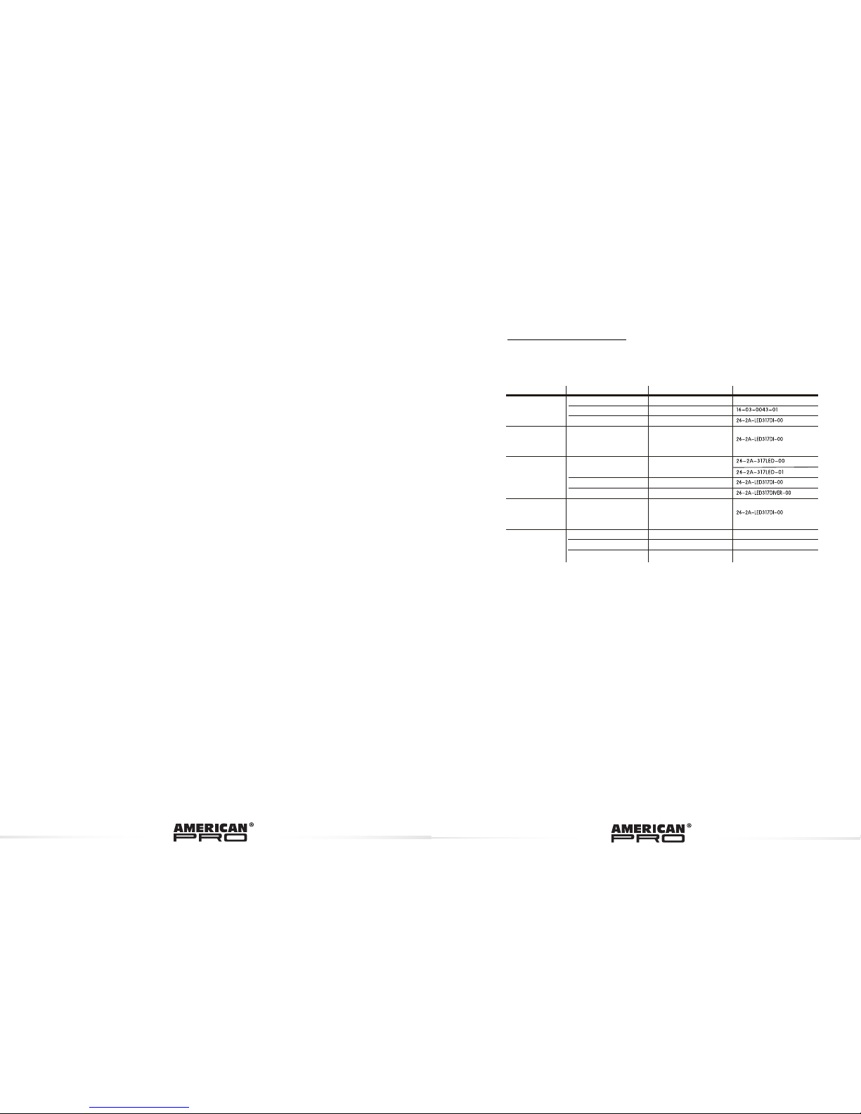
Cleart front plate
Completed lens set
LED PCB A
LED PCB B
Heat sink board
Power supply
Display PCB
Fan
Side cover
LED driver PCB
Fuse
Supporting bracket
No
ITEM
Power output socket(white)
Power output socket(blue)
11
12
13
14
No
ITEM
5.2 MAINTENANCE
USER MANUAL
Please read the manual before installing and using ithis lighting device
Keep it for future reference
SION
www.neo-professional.com
Page 2
ABLE OF CONTENTS
T
No display
1) Power connection error
2) Power supply error
3) Main PCB damaged
1) Check all power connections
2) Replace power supply
3) Replace main PCB
LED MODULE on,
but no control
from display
Main PCB amaged
Replace Main PCB
LEDs of the same
color are not lit
1) LED PCB damaged
1) Replace PCB board
LEDs of all colors
are not lit
Main PCB damaged
Replace main PCB
Display normal,
but no respon
se to DMX512
controller
1) Signal connection error
2) DMX address error
1) Check all signal connections
2) Check DMX address setting
SITUATION CAUSE
PART ORDER NUMBER
ACTION
2) Main PCB damaged
2) Replace Main PCB
3) Driver PCB damaged
3) Replace Driver PCB
5.1 TROUBLE SHOOTING
5 APPENDIX
PART 1 PRO DUCT (GENE RAL)................................................................. 1.
1.1--PRODUCT INTRODUCTION........................................................................1.
1.2--PRODUCT FEATURES................................................................................1.
1.3--TECHNICAL SPECIFICATIONS...................................................................2 .
1.4--PHOTOMETRIC DATA.................................................................................3.
1.5--SAFETY WARNING.....................................................................................4.
PART 2 INSTA LLATION ............................................................................5.
2.1--MOUNTING................................................................................................ 5.
2.2--POWER CONNECTION...............................................................................5.
2.3--SETTING UP WITH A DMX512 CONTROLLER.............................................. 6.
2.3-1--DMX512 ADDRESSING WITHOUT ID ADDRESSING
...........................................6.
2.3-2--DMX512 ADDRESSING WITH ID ADDRESS
...........................................................7.
PART 3 DISPLAY PANEL OPERATION........................................................8.
3.1--BASIC.........................................................................................................8.
3.2--MENU........................................................................................................ .8.
3.3--STATIC........................................................................................................9.
3.4--AUTO PLAY MODE......................................................................................10.
3.5-- DMX ADDRESS.........................................................................................10.
3.6--RUN MODE................................................................................................10.
3.7--PERSONALITY.......................................................................................... 10.
3.8--ID ADDRESS..............................................................................................11.
3.9--
SPECIAL SETTINGS ..................................................................................11.
3.10--FACTORY DEFAULT SETTING...................................................................12.
3.11--EDIT CUSTOM .........................................................................................12.
3.12-- WHITES SETTING ..................................................................................12.
3.13--FAN SETTING ..........................................................................................13.
3.14--ACTIVATE THE PASSWORD.....................................................................13.
.
PART 4 USING A DMX512 CONTROLLER...................................................14.
4.1--BASIC ADDRESSING................................................................................. 14.
4.2--CHANNEL ASSIGNMENT............................................................................14.
4.3--BASIC INSTRUCTIONS FOR DMX512 OPERATION (TOUR) ........................ 20.
4.4--BASIC INSTRUCTIONS FOR DMX512 OPERATION (BLOCK 1 & 2)............... 20.
PART 5 APPENDIX....................................................................................21.
5.1--TROUBLE SHOOTING................................................................................21.
5.2--
MAINTENANCE..........................................................................................22.
Page 3

1.1 PRODUCT INTRODUCTION
1.2 PRODUCT FEATURES
LED FIXTURE
* RGBWA Dimmer 0-100%
* Strobe
* Automatic programs
* Custom programs
* LCD display
* Display control 'lock-out'
* Direct DMX512 input
* Independent ID address
* Lightweight aluminium casing
* Different white colors setting
This product is designed for indoor use. Suitable applications
include wash o r effect lighting for stage, nightclub or touring
applications. Direct input of DMX512 signal allows the units to
be controlled from any DMX512 controller. This product can be
operated as a single unit or in multiple units for large applications.
1 PRODUCT (GENERAL)
4.3 BASIC INSTRUCTIONS FOR DMX512
OPERATION (TOUR)
MASTER DIMMER
CH1 controls the intensity of the currently projected color
When the slider is at the highest position (255) the intensity of the output is the
maximum
RED, GREEN BLUE, WHITE & AMBER COLOR SELECTION
CH2, CH3 & Ch4, Ch5 & CH6 control the intensity ratio of each of the RED,
GREEN, BLUE, WHITE & AMBER LEDs.
When the slider is at the highest position (255) the intensity of the color is the
maximum.
CH2, CH3, Ch4 , Ch5 & CH6can be combined together to create over 16
million colors.
COLOR MACROS AND WHITE BALANCE
CH7 selects the required COLOR MACRO and whites in different color temp.
Ch7 has priority over CH2, CH3, CH4, CH5 , Ch6 & CH9.
CH1 is used to control the intensity of the COLOR MACRO
STROBE
CH 8 controls the strobe of CH2 to CH7.
ID ADDRESS SELECTION
CH12 is used to select the target ID address.
Each independent DMX address may have upto 66 independent ID addresses.
An ID address of 0 will activate all ID address locations.
AUTO
CH9
selects the preset
AUTO programs AUTO 1-AUTO10 or the custom
programs CUSTOM1-CUSTOM 10.
Ch9 has priority over Ch2, Ch3, Ch4 , Ch5 & Ch6..
BLOCK SELECTION
Ch13 channel allows the user to select from combinations of different
colors and LED blocks in a quick-and-easy action
4.4 BASIC INSTRUCTIONS FOR DMX512
OPERATION (BLOCK 1 & 2)
BLOCK 1
All leds divided as 3 blocks, each block include 6 red leds, 6 green leds and 6
blue leds.
BLOCK2
All leds divided as 3 blocks, each block include 6 red leds, 6 green leds, 6 blue
leds, 3 white leds and 3 amber leds.
Page 4
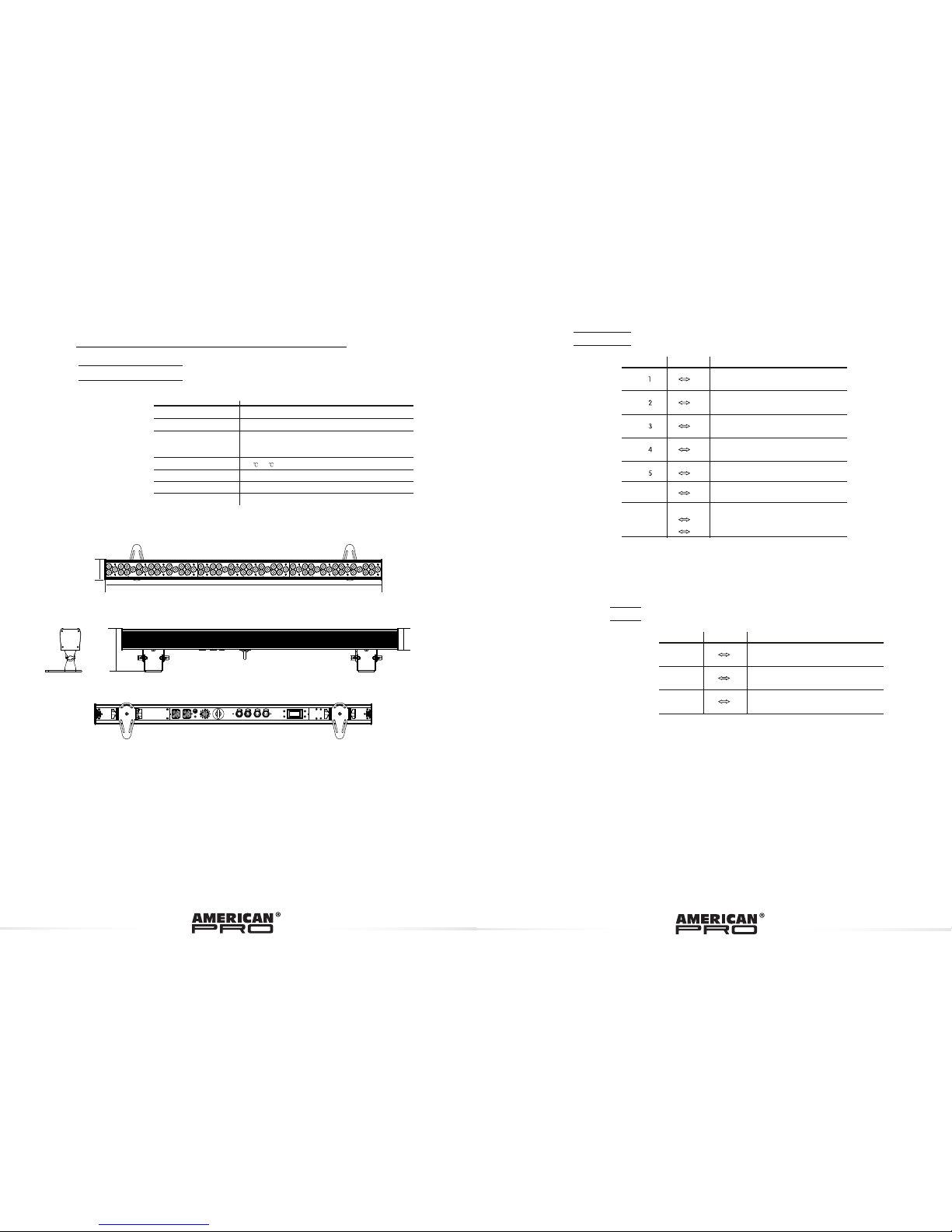
990mm
75mm
156mm
77mm
1.3 TECHNICAL SPECIFICATIONS
LE D M OD U L E
Dimensions
LED MODULE:
Voltage
Rated Power
18 x 1W RED / 18 x 1W GREEN /
18 x 1W BLUE/ 9 x1W WHITE / 9 x AMBER
Weight
LED/Unit
Cooling
990 x 156 x 75mm
6Kg
100~240V...50/60Hz
87W
Environment Temperature
-20 ~40
Forced air convection
1
2
0 255
3
0 255
0 255
HSV
HUE
SATUR ATION
VALU E
CHA NNEL
VALU E
FUN CTION
0 255
0 255
0 255
0 255
BLUE
ARC 2+ S
MAST ER DIM MER
RED
G REE N
VALU E
FUN CTION
0 255
WHITE
6
0 255
AMBE R
7
0 9
NO F UNC TIO N
1~ 20Hz
10 2 55
STROB E
CHANNEL
Page 5
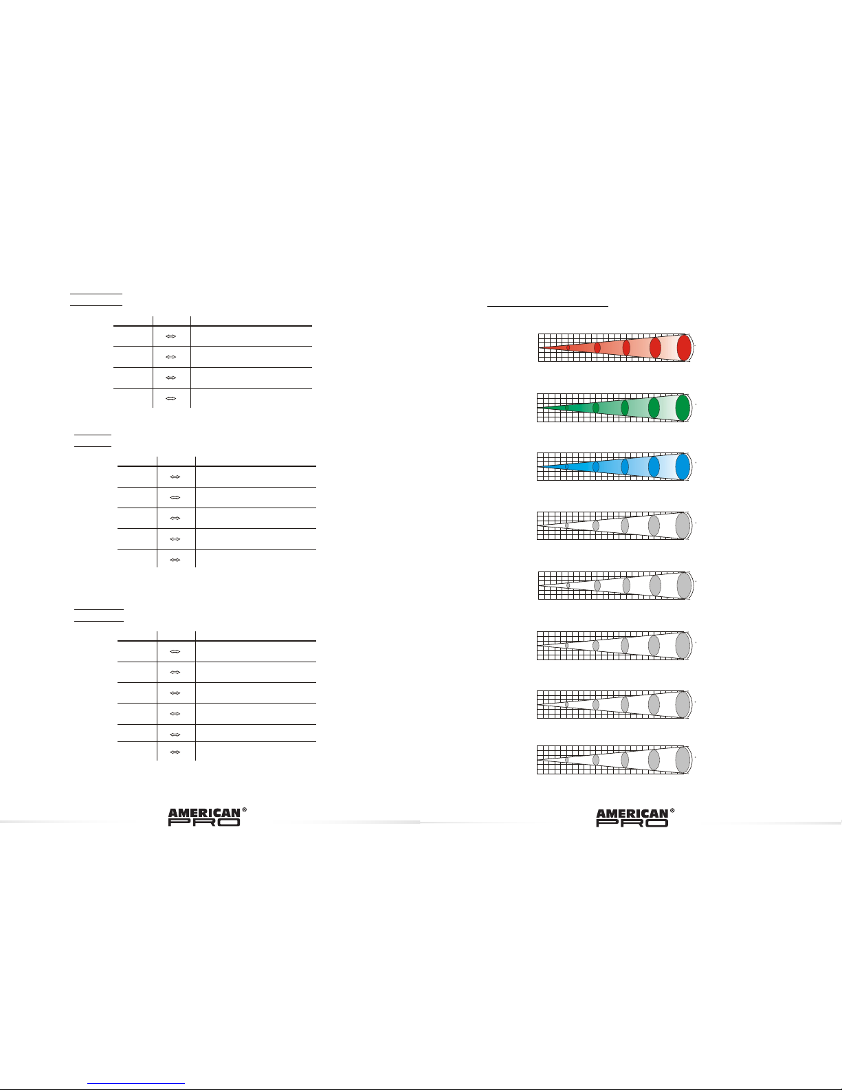
1.4 PH OT OM ETR IC D ATA
1
2
0 255
3
4
0 255
0 255
0 255
BLUE
ARC 2+ D
MAST ER DIMM ER
RED
GREE N
VALU E
FUN CTI ON
5
0 255
WHIT E
6
0 255
AMBE R
CHANNEL
1
2
0 255
3
4
0 255
0 255
0 255
BLUE
MAST ER DIMM ER
RED
GREE N
VALU E
FUN CTI ON
CHANNEL
ARC 1+ D
1
2
0 255
3
4
0 255
0 255
0 255
BLUE
ARC 2
RED
GREE N
VALU E
FUN CTI ON
5
0 255
WHIT E
AMBE R
CHANNEL
1
2
3
0
1
2
3
2
4
6 8
10Di stanc e(m)
1316
329 146 82 53 L UX
15
R
1
2
3
0
1
2
3
2
4
6 8
10Di stanc e(m)
600
150 67 38 24 L UX
A
15
1
2
3
0
1
2
3
2
4
6 8
10Di stanc e(m)
3402
850 378 213 136 LU X
RGBW
15
1
2
3
0
1
2
3
2
4
6 8
10Di stanc e(m)
350
87 40 22 14 LUX
B
15
1
2
3
0
1
2
3
2
4
6 8
10Di stanc e(m)
3893
973 433 24 3 156LU X
RGBWA
15
1
2
3
0
1
2
3
2
4
6 8
10Di stanc e(m)
566
142 63 35 23 L UX
W
15
RGB
1
2
3
0
1
2
3
2
4
6 8
10Di stanc e(m)
2795
700 310 17 5 112 LUX
15
G
1
2
3
0
1
2
3
2
4
6 8
10Di stanc e(m)
1300
325 145 81 52 L UX
15
Page 6

1.5 SA FE TY WARNI NG
IMPO RTANT
ALWAYS RE AD THE US ER MANU AL BEFO RE OPER ATION.
PLE ASE CON FIRM TH AT THE POWE R SUPPLY STAT ED ON THE
PRO DUCT IS T HE SAME AS T HE MAIN S POWER S UPPLY IN YO UR
ARE A.
This product must be installed by a qualified professional.
Always operate the equipment as described in the user manual.
A minimum distance of 0.5m must be maintained between the
equipment and combustible surface.
The product must always be placed in a well ventilated area.
Always make sure that the equipment is installed securely.
DO NOT stand close t o the equipment and stare directly into the LED
light source.
Always disconnect the power supply before a ttempting and
maintenance.
Always make sure that the supporting structure is solid and can
support the combined weight of the products.
The earth wire must always be connected to the ground.
Do not touch the power cables if your hands are wet.
ATT EN T ION
This product left the place of manufacture in perfect condition. In
order to maintain this condition and for safe operation, the user must
always follow the instructions and safety warnings described in this
user manual.
Avoid shaking or strong impacts to any part of the equipment.
Make sure that all parts of the equipment are kept clean and free of
dust.
Always make sure that the power connections are connected correct
and secure.
If there is any malfunction of the equipment, contact your distributor
immediately.
When transferring the product, it is advisable to use the original
packaging in which the product left the factory.
Shields, lenses or ultraviolet screens shall be changed if they have
become damaged to such an extent that their effectiveness is
impaired.
The lamp (LED) shall be changed if it has become damaged or
thermally deformed.
BLOCK1 RE D
BLOCK1 GR EEN
BLOCK1 BLU E
0
255
0
0
255
255
0
255
0
255
0
255
0
255
0
0
255
255
1
2
3
4
5
6
7
8
9
BLOC K1
14
15
0
255
0
0
255
255
0
255
0
255
0
255
0
255
0
0
255
255
0
255
0
255
1
2
3
6
7
8
11
12
13
BLOC K2
0
255
0
255
4
5
0
255
0
255
9
10
ARC 1
VALU E
FUN CTION
CHANNEL
BLOCK2 RE D
BLOCK2 GR EEN
BLOCK2 BLU E
BLOCK3 RE D
BLOCK3 GR EEN
BLOCK3 BLU E
BLOCK1 RE D
BLOCK1 GR EEN
BLOCK1 BLU E
BLOCK1 WHI TE
BLOCK1 AMBER
BLOCK2 RE D
BLOCK2 GR EEN
BLOCK2 BLU E
BLOCK2 WHI TE
BLOCK2 AMBER
BLOCK3 RE D
BLOCK3 GR EEN
BLOCK3 BLU E
BLOCK3 WHI TE
BLOCK3 AMBER
1
3
4
0 255
0 255
0 255
BLUE
RED
GREE N
VALU E
FUN CTION
CHANNEL
VALU E
FUN CTION
CHANNEL
Page 7
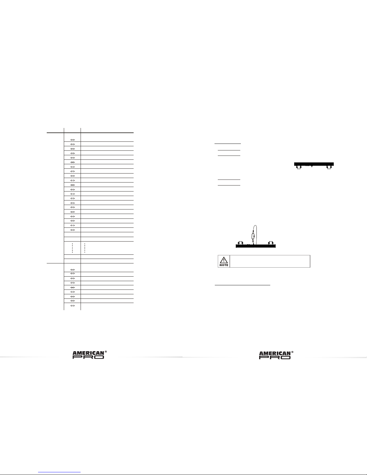
2.1 MOUNTING
UPRI GHT
The LED MODULE can be
mounted in an upright or sitting
position using the supporting
brackets.
@ 220V: 12 units may be connected in series
@120V: 6 units may be connected in series
The LED MODULE can be mounted at any angle . It is possible to
further adjust the angle of the LED MODULE using the
adjustment knobs located on the side of the fixture.
2.2 POWER CONNECTIONS
HANG ING
The LED MODULE can be mounted in a hanging position using
the support frame. It is possible to use any bolt of the correct
size and strength to mount the fixture. It is recommended to
use at least 2 mounting points per fixture. Mounting with a
clamp or other mounting bracket is recommended depending
on the requirements of your application.
For overhead use, always install two secure-chains that can
hold at least 10 times the weight of the fixture.
2 INSTALLATION
Note: If over 30 units to be connected, then a DMX signal amplifier
is needed.
12
ID ADD RESS
ID1~ ID66
ID1
ID2
ID3
ID4
ID5
ID6
ID7
ID8
ID9
ID10
ID11
ID12
ID13
ID14
0 9
10 19
20 29
30 39
40 49
50 59
60 69
70 79
80 89
90 99
100 109
110 119
120 129
130 139
140 149
ID19
ID20
190 199
200 209
ID21
ID22
210
211
ID65
ID66
254
255
ID15
ID16
ID17
150 159
160 169
170 179
ID18180
189
13
BLOC K SELEC TIONS
BLOC K1, BLO CK2, BL OCK3
0 4
5 34
35 64
65 94
95 124
125 154
155 184
215 255
BLOC K1
BLOC K2
BLOC K3
BLOC K1, BLO CK2
BLOC K2, BLO CK3
BLOC K1, BLO CK3
185 241
BLOC K1, BLO CK2, BL OCK3
NO FUN CTION
VALU E
FUN CTION
CHANNEL
Page 8
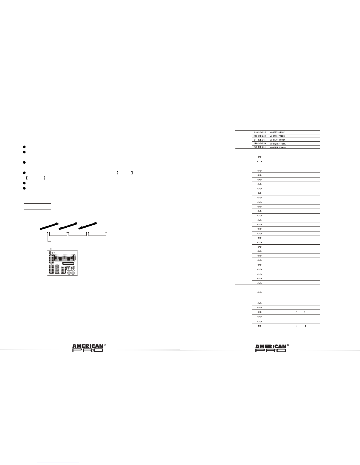
2.3 SETTING UP WITH A DMX512 CONTROLLER
2.3-1 DMX512 ADDRESSING WITHOUT ID ADDRESSING
(TOUR MODE)
The figure above shows a simple DMX512
layout with the starting address of the first
unit set at 1, with the second set at 13 and
so on... (Note that when used in this way,
the Ch12 ID function must be inactive
(CH13=0))
DMX512
CONTROLLER
Connect the DMX512 controller to the units in series.
Each unit has 13 DMX channels so the DMX Addresses should increase by
increments of 13 (e.g. 1,14,,27...)
The ID address has not been set so therefore when using the controller CH12
must be inactive ( CH12=0 ).
It is also possible to deactivate ID address selecting ID OFF from the
Settings menu. on the fixture
Each DMX Address may be used as many times as required.
Any DMX address in the range from 001 to 512 may be used.
Exam ple:
............
DMX Addr.1 DMX Addr.14 DMX Addr.27
0 255
AUTO S PEED
10
AUTO S PEED FO R Auto1~ Auto1 0
Auto 6
Auto 7
Auto 8
Auto 9
111 1 20
Auto 1 0
121 13 0
131 14 0
141 15 0
151
160
161
170
Cust om 2
Cust om 1
171
180
181
190
191
200
201 210
211 22 0
0
9
10 29
30 69
70 129
Cust om 3
Cust om 4
Cust om 5
Cust om 6
0 10
11
20
21 30
31 40
41
50
9
61
70
81
90
91
100
101 110
Auto 1
Auto 2
Auto 3
Auto 4
Auto 5
71
80
51
60
8
0 9
10 255
11
130 18 9
190 2 55
221 230 C ustom 7
231 240 C ustom 8
241 250
Cust om 9
251 255 C ustom 1 0
1~20Hz
NO FUNCTION
STROBE
FANS OFF (STAY 3 SECONDS)
FANS LOW (STAY 3 SECONDS)
FANS NORMAL (STAY 3 SECONDS)
FANS HIGH (STAY 3 SECONDS)
FANS AUTO (STAY 3 SECONDS)
AUTO + CUSTOM PROGRAMS + FAN CONTROL
NO FUNCTION
DIMMER SPEED
LINEAR DIMMER
NON LINEAR DIMMER 1 fastest
NON LINEAR DIMMER 2
NON LINEAR DIMMER 3
NON LINEAR DIMMER 4 slowest
PRESET DIMMER SPEED FROM DISPLAY MENU
7
VALU E
FUN CTION
CHANNEL
Page 9

2.3-2 DMX512 ADDRESSING WITH ID ADDRESS (TOUR MODE)
Connect the DMX512 controller to the units in series
Each unit has 10 DMX channels so the DMX Addresses should increase by
increments of 13 (e.g. 1,14,27...)
Each DMX Address may be used as many times as required.
Any DMX address in the range from 001 to 512 may be used.
Each DMX address may carry up to 66 separate ID addresses.
ID should be set in the menu on each unit in ascending values
(i.e. 1,2,3...)
ID On should be set in the Settings menu on each unit.
ID addresses are accessible from Ch12 on the DMX512 controller.
TOUR
Note: This product have three DMX512 channel configuration:
TOUR , BLOCK1 , , ARC 1 , ARC 1+D ,
2 , 2 and HSV
BLOCK2 ARC
ARC +D
4.1 BA SIC AD DR ESS IN G
Connect all of the units in series using standard DMX512 signal cable or
the IP65 rated cable provided.
Set the DMX512 address in the DMX menu.
It is possible to have the same DMX address or independent
addresses for each fixture.
4.2 CH ANNEL AS SI GNM EN T
4 USING A DMX512 CONTROLLER
1
2
3
4
C OLO R M AC R O + WHITE B ALAN C E
5
6
BLUE
MAST ER DIM MER
RED
G REE N
VALU E
FUN CTION
WHITE
AMBE R
CHANNEL
Example:
DMX Addr.1
ID Addr.1
DMX Addr.1
ID Addr.2
DMX Addr.1
ID Addr.3
DMX Addr.14
ID Addr.1
DMX Addr.14
ID Addr.2
DMX Addr.14
ID Addr.3
DMX5 12
CONT ROLLE R
The f igure a bove sh ows a sim ple DMX l ayout
whi ch has us ed thre e units a t each DM X addre ss.
The t hree un its hav e diffe rent ID a ddres ses whi ch
allow s the use r to collec tivel y contr ol the wh ole
gro up of uni ts at tha t DMX add ress by s ettin g
CH1 2 to 0, or to c ontro l each un it inde pende ntly by
fir st sele cting t he DMX ad dress a nd then b y using
Ch1 2 to loca te the ta rget ID a ddres s.
... ..... ....
7
Page 10

UP
ENTER
DOWN
MENU
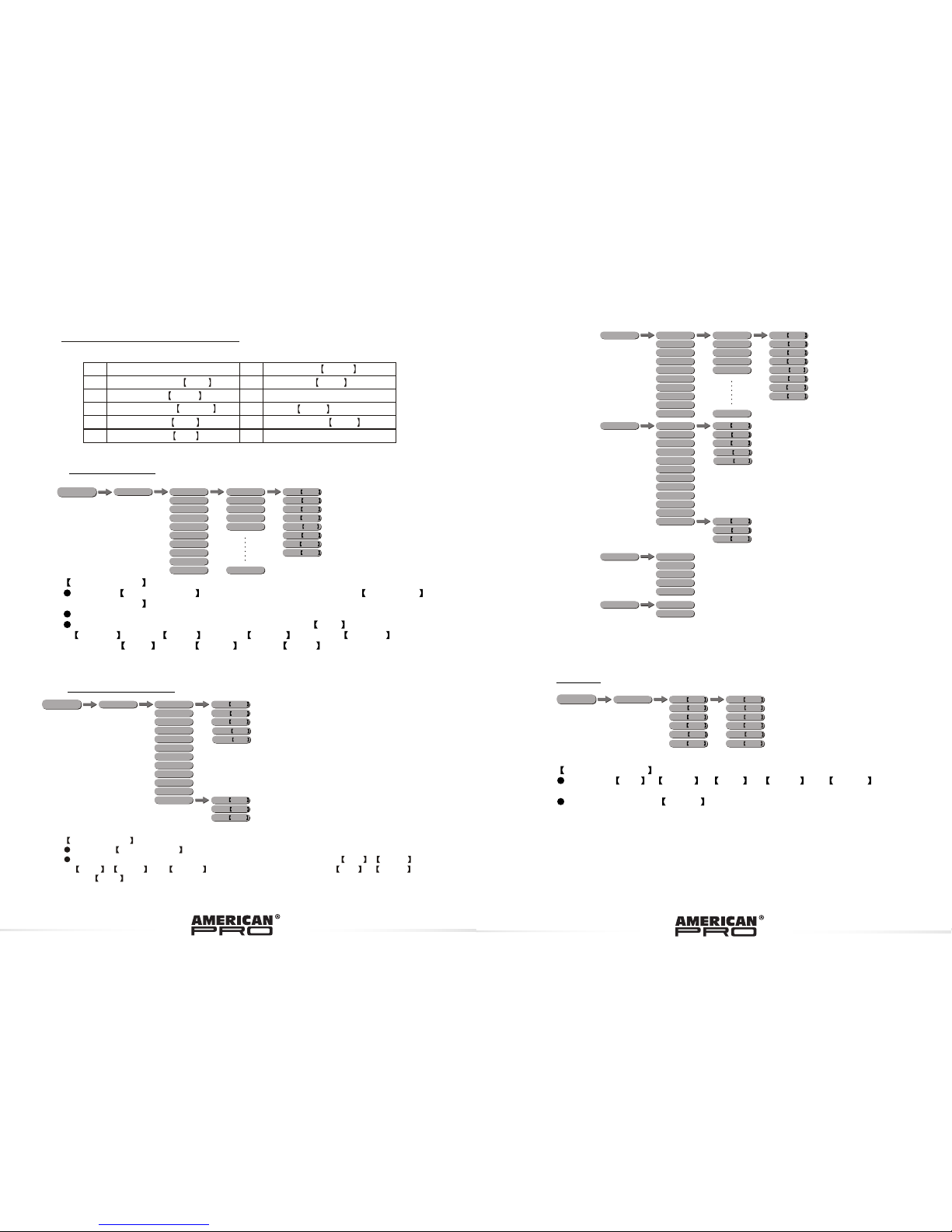
3.2 M ENU
RUN
PERS ON
SLAVE
DMX
ADDERSS
TOUR
BLOC K1
BLOC K2
ARC 1
ID
1~66
1~512
ARC 1+ D
ARC 2
STATIC
GREN 0~255
RED 0~255
BLUE 0 ~255
WHIT 0 ~255
AMBE 0 ~255
STRB 0 ~020
ARC 2+D
ARC 2+S
GREN 0~255
RED 0~255
BLUE 0 ~255
WHIT 0 ~255
AMBE 0 ~255
STRB 0 ~020
SETT INGS
UPLO AD
PASSWORD
RESE T
PASSWORD
ID ONOF F
OFF
ON
****
SEND ... END
****
RESE T...
DIMM ER
DIM1
OFF
DIM3
DIM2
DIM4
COLO R
RGB TO W
OFF
UC
HSV
MENU
enter the currently selected menu or confirm the current function value
scroll 'UP' through the menu list or increase the value of the current function
scroll 'DOWN' through the menu list or decrease the value of the current function
scroll through the main menu or return to the main menu
MENU
ENTER
3.1 BASIC
3 DISPLAY PANEL OPERATION
3.13 FAN SETTING
FAN SETTING
Enter the FAN SETTING to select the fan speed mode OFF ,
LOW , NORM , HIGH or AUTO .
When fan setting is on AUTO mode, the fixture will automatic adjust the
fan speed and fixture power, ensure the fixture temperature is not exceed
the limit.
When fan setting is on other modes, the fan will run according to the set
speed.
.
KEY-LOCK
Enter the KEY-LOCK mode to select whether the access password is on
or off.
Access password is UP + DOWN + UP + DOWN .
3.14 ACTIVATE THE PASSWORD
FANS OFF
LOW
NORM AL
HIGH
AUTO
MENU
KEYL OCK
OFF
ON
MENU
AUTO AUTO 01
AUTO 1 0
CUST OM 01
CUST OM 02
CUST OM 03
CUST OM 04
CUST OM 05
CUST OM 06
CUST OM 07
CUST OM 08
CUST OM 09
CUSTOM 1 0
SP 0~255
Page 11
EDIT CUST OM 01
CUST OM 02
CUST OM 03
CUST OM 04
CUST OM 05
CUST OM 06
CUST OM 07
CUST OM 08
CUST OM 09
CUSTOM 1 0
SCEN E 01
SCEN E 02
SCEN E 03
SCEN E 04
SCEN E 05
SCEN E 30
GREN 0~255
RED 0 ~255
BLUE 0~255
STRB 0~020
TIME 0~255
FADE 0~031
WHIT 0~255
AMBER 0~255
WHIT E1
WHIT E2
WHIT E3
WHIT E4
WHIT E5
WHIT E6
WHIT E7
WHIT E8
WHIT E9
WHIT E10
WHIT E11
RGB TO W
GREN 0~255
RED 0 ~255
BLUE 0~255
CALI B
FANS OFF
LOW
NORM AL
HIGH
AUTO
KEYL OCK
OFF
ON
3.3 STATI C
STATI C CO LOUR
Combi ne Red , Gr ee n , Blue , Wh it e and A mb er to cr ea te
an infi ni te ran ge of col or s (0 -2 55)
Set the v al ue o f th e Stro be (0-20H z)
EDIT CUST OM 01
CUST OM 02
CUST OM 03
CUST OM 04
CUST OM 05
CUST OM 06
CUST OM 07
CUST OM 08
CUST OM 09
CUSTOM 1 0
SCEN E 01
SCEN E 02
SCEN E 03
SCEN E 04
SCEN E 05
SCEN E 30
GREN 0~255
RED 0 ~255
BLUE 0~255
STRB 0~020
TIME 0~255
FADE 0~031
WHIT 0~255
AMBER 0~255
MENU
3.11 EDIT C USTOM
3.10 FA CTORY DEFAU LT SE TTING
2
3
4
5
7
8
9
DMX add re ss = 001
ID ON /O FF = ON
COLOR = OFF
KEYLO CK = OFF
Parso na li ey = TOU R
Run mod e = D MX
10
Fan = Au to
1
STATI C =0 00
ID addr es s = 0 01
6
DIMME R = D IM 4
EDIT = 00 0
11
WHIT E1
WHIT E2
WHIT E3
WHIT E4
WHIT E5
WHIT E6
WHIT E7
WHIT E8
WHIT E9
WHIT E10
WHIT E11
RGB TO W
GREN 0~255
RED 0 ~255
BLUE 0~255
CALI B
MENU
3.12 W HI TES S ET TING
EDIT CUSTOM
Enter the EDIT CUSTOM mode to edit the custom programs
to
Each custom program has 30 steps that can be edited.
Each step allows the creation of a scene using RED RED , GREEN
GREEN , BLUE BLUE ,WHITE WHITE , AMBER AMBER ,
STROBE Stro. , TIME TIMER & FADE FADE .
CUSTOM 1
CUSTOM 10 .
STATIC
GREN 0~255
RED 0~255
BLUE 0 ~255
WHIT 0 ~255
AMBE 0 ~255
STRB 0 ~020
GREN 0~255
RED 0~255
BLUE 0 ~255
WHIT 0 ~255
AMBE 0 ~255
STRB 0 ~020
MENU
WHITE 0~255
AMBER 0~ 255
WHITE 0~255
AMBER 0~ 255
GREN 0~255
RED 0 ~255
BLUE 0~255
GREN 0~255
RED 0 ~255
BLUE 0~255
WHITE CALIB
Enter the WHITE CALIB to select white color of different color temperature.
There are 11 pre-programmed White colors can be edited by using Red , Green ,
Blue , White and Amber , and RGB TO WHITE by using Red , Green
and Blue .
Page 12

MENU
3.4 A UTO PLAY MODE
3.7 PE RSONA LI TY
AUTO PLAY MODE
Select the target Auto program .
Programs AUTO 01 to AUTO 10 are fully pre-programmed and will not be
altered by changes in EDIT CUSTOM mode. The auto speed can be set from
SP 1~255 .
Programs CUSTOM 01 to CUSTOM10 are fully pre-programmed and can
be edited in EDIT CUSTOM mode.
3.5 DMX ADDRESS
DMX ADDRESS
Enter the DMX ADDRESS mode to set the DMX ADDRESS.
RUN MODE
Enter the RUN MODE mode to set working mode.
DMX mode is for using the DMX512 controller to control the fixtures.
SLAVE mode is for Master -- Slave operation, or controlled fixture by
Pix-controller.
Note: When fixtures are under Auto program operation, the RUN MODE does
no works.
3.6 RUN MODE
PERSONALITY
Enter the PERSONALITY mode to select DMX mode: ,
, , , , , ,
or .
3.8 ID ADDRE SS
3.9 SP ECIAL SET TI NGS
SETT INGS
UPLO AD
PASSWORD
RESE T
PASSWORD
ID ONOF F
OFF
ON
****
SEND ... END
****
RESE T...
DIMM ER
DIM1
OFF
DIM3
DIM2
DIM4
COLO R
RGB TO W
OFF
UC
MENU
ID ADDRESS
Enter the ID ADDRESS mode to set the ID ADDRESS.
SETTING
Enter ID in order t o allow/disallow ID address function from the DMX512
controller.
Select UPLD to upload the custom programs from the current MASTER unit to
the SLAVE units.
In order to activate the upload function the password must be entered.
Password is the same as the main access password.
When uploading the MASTER and SLAVE units will display YELLOW.
If an error occurs when uploading the MASTER and/or SLAVE units will display RED.
On successful uploading of the custom programs the MASTER and SLAVE units
will display GREEN.
In order to reset custom modes to default values select REST .
Enter Dim to select dimmer mode and dimmer speed. When DIMMER is
set to Off , then RGBW and MASTER DIMMER are linear. The Dim 1/2/3/4
are speed modes of the non linear dimmer , Dim1 is the faster, while
Dim4 is the slowest.
The factory default setting is Dim4 .
COLOR is for activate/unactivate the color calibration functions.
When RGBW is selected, on RGB = 255,255,255, the color is displayed
as
calibrated in CAL2 -- RGBW. When COLOR is set OFF , on RGB = 255,255,
255, the RGB values are not adjusted and the output is most powerful.
When [UC] is selected, the RGB output are adjusted to a standard preset universal color
which balances fixtures from different generations..
ADDERSS
1~512
MENU
RUN
SLAVE
DMX
MENU
PERS ON
TOUR
BLOC K1
BLOC K2
ARC 1
ARC 1+ D
ARC 2
ARC 2+D
ARC 2+S
HSV
MENU
ID
1~66
MENU
AUTO AUTO 01
AUTO 1 0
CUST OM 01
CUST OM 02
CUST OM 03
CUST OM 04
CUST OM 05
CUST OM 06
CUST OM 07
CUST OM 08
CUST OM 09
CUSTOM 1 0
SP 0~255
 Loading...