

Page 1

PLEASE READ THE INSTRUCTIONS CAREFULLY BEFORE USE /
POR FAVOR LEA LAS INSTRUCCIÓNES ANTES DE USAR
USER MANUAL / MANUAL DE USUARIO
PROTON
IP QW ZOOM
Page 2

PROTON IP QW ZOOM
P.
2
1. OVERVIEW
Proton IP QW ZOOM is an outdoor professional washer
powered by 1 RGBW 60W LED with a 6º-23º motorized
zoom. Ideal for broadcasting applications, the unit has adjustable PWM, to work flicker free in any given situation,
and also sports on-board white balance, to adjust your
light source from 2000 to 8000K. Proton IP QW Zoom is
equipped with a 16-bit dimmer with 4 dimming curves, internal RGBW color mix, color macros and a friendly and
powerful OLED display. Regarding its outdoor nature, the
fixture is rated as a IP65 unit, making it ideal for long-term
outdoor applications.
SPECIFICATIONS
Source & Optic
• Light Source: 1 RGBW 60W LED
• LEDs life: 50,000 hours
• Motorized zoom: 6º-23º
Photometric Data
• 6º Beam angle: 3,034 lux @ 16 ft.
• 23º Beam angle: 212 lux @ 16 ft.
Effects & Functions
• Quad-color LED technology: Smooth RGBW mix
with no multi colored shadows
• Color macros and rainbow effect
• Dimmer: 0-100% general & for all colors
• 4 dimming curves
• Strobe effect: 1-30 Hz
• Pulse effect
• Adjustable PWM (Pulse Width Modulation) to
work flicker free in any given situation
• White balance control on-board
• Gel Frame included
• Heavy duty case
• Very silent operation
• Control
• DMX Channels: 5/7/11
• Operational modes: DMX, Master/Slave, Au-
to-run and Static Colors
• Electrical
• Input voltage range: AC100–240V, 50-60Hz
• Power consumption: 89W
• Power linking:
• 110V: Up to 12 units
• 220V: Up to 22 units
Physical
• IP Rating: IP65
• OLED display
• DMX connectors: 2 XLR connectors (XLR-5 in-
put and output)
• Powercon® IP65 In/Out power supply connectors
• Dimensions: 347x260x265 mm. / 13.7x10x10.4 in.
• Weight: 5.5 Kg. / 12 Lbs.
ENGLISH VERSION
Page 3

PROTON IP QW ZOOM
P.
3
2. SAFETY INSTRUCTIONS
1. Before delivery, this device has passed strict in spection, Please follow the user manual strictly
for operation, if this fixture is damaged by im-
proper operation and mistake, the fixture will be
out of warranty, and manufacture or dealer won’t
be responsible for it. In case of any technology
change in this manual,we won’t advise in further
.
2. Aer you have received this product, please pay
special attention and check cautiously whether
the product was damaged or not during the
transportation, if it is, please do not use this fix ture and contact local dealers or manufacturers
as soon as possible.
3. The applicable temperature for the lighting is be low 40°C. Do not use the lighting above the temp
erature.
4. It must be kept clean; please do not use it around
overheat or dusty environment. Do not touch the
Chemical liquid.
5. Read the instructions before installing anything.
Pay attention to the manual and warning signs
on the equipment, if you have any other ques tions, please contact the dealer or manufacturer
as soon as possible.
6. Any break, please contact professionals: repairs
must be done by technical personnel.
7. Do not power in and open before installation. Let
have a rest when continuous work for eight hours.
It will longer the device using li.
8. Fixed installation, to prevent the strong vibration
or impact of the device.
9. The distance between the device and the projec tile must be at least 0.5 meter.
ENGLISH VERSION
10. Never look directly into the light source, as sen sitive persons may suer an epileptic shock (espe-
cially meant for epileptics)! When light output
position of the device of dustproof glass break age, cracks or other visible damage, user should
replace the new glass to continue to use.
• WHAT’S INSIDE
• PROTON IP QW ZOOM - Power cord
• User Manual
• Warranty Card
Page 4

PROTON IP QW ZOOM
P.
4
ENGLISH VERSION
3. MAINTENANCE AND CLEANING THE UNIT
• Make sure the area below the installation place is
free from unwanted persons during setup.
• Switch off the unit, unplug the main cable and wait
until the unit had cooled down.
• All screws used for installing the device and any
of its parts should be tightly fastened and should
not be corroded.
• Housings, fixations and installation spots (ceilling,
trusses, suspensions) should be totally free from
any deformation.
• The main cables must be in impeccable condition
and should be replaced immediately even when a
small problem is detected.
• It is recommended to clean the front at regular
intervals, from impurities caused by dust, smoke
or other particles to ensure that the light is radi ated at maximum brightness. For cleaning, discon nect the main plug from the socket. Use a soft,
clean cloth moistened with a mild detergent. Then
carefully wipe the part dry. For cleaning other
housing parts use only a soft, clean cloth. Never
use a liquid, it might penetrate the unit and cause
damage to it.
Page 5
PROTON IP QW ZOOM
P.
5
ENGLISH VERSION
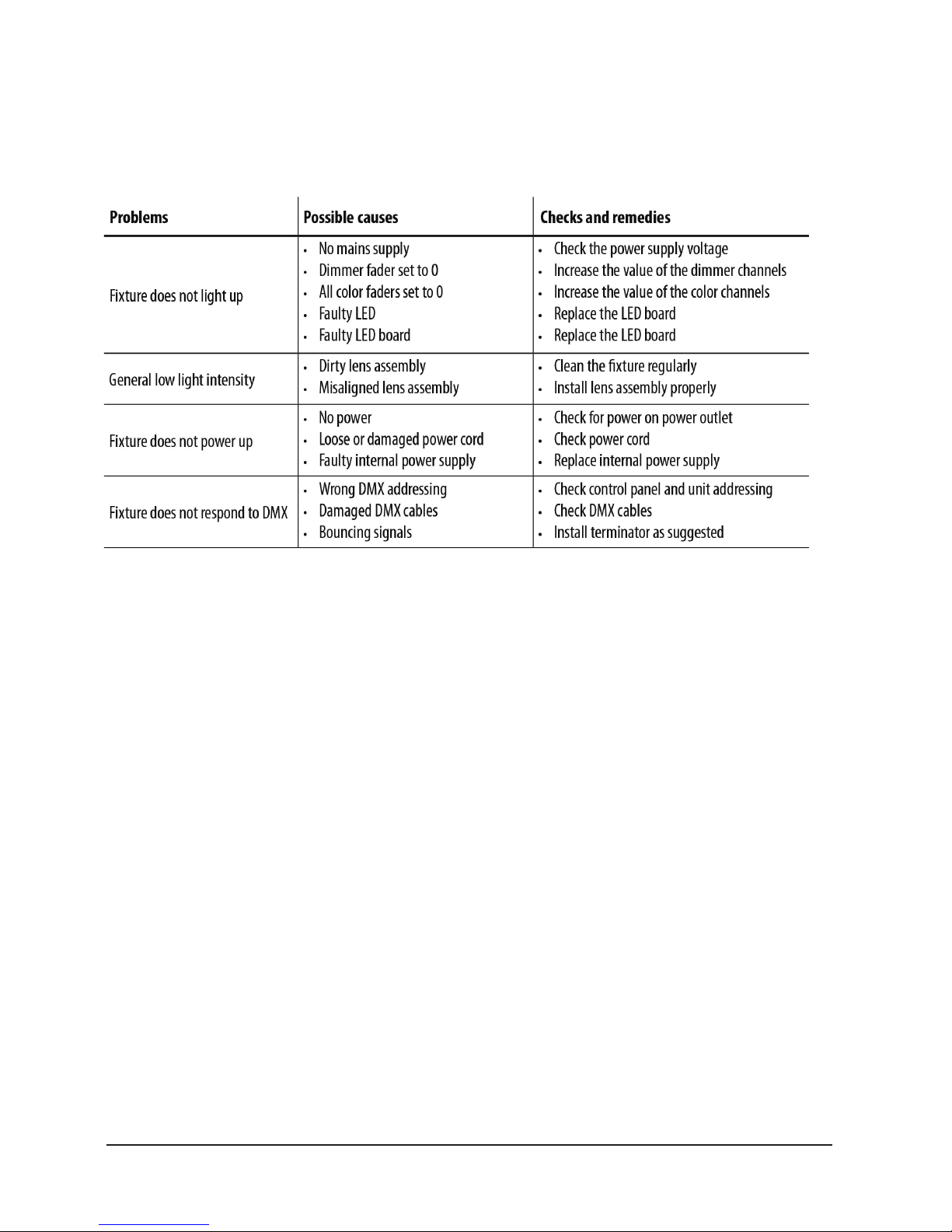
TROUBLESHOOTING
Page 6
PROTON IP QW ZOOM
P.
6
ENGLISH VERSION
4. INTRODUCTION
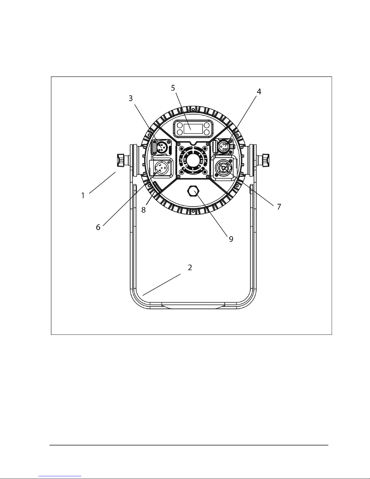
Rear Panel
1. Tighting Kbob
2. MOUNTING BRACKET
3. DMX IN (5-pin IP65 XLR):
- Ground,
- DMX -
- DMX +
4. DMX OUT (5-pin IP65 XLR):
- ground,
- DMX -
- DMX +
5. CONTROL PANEL with display and 4 button used
to access the control panel functions and manage them
6. POWER IN (IP65 PowerKON): for connection to
100-240V~/50-60Hz power via the supplied mains cable
7. POWER OUT (IP65 PowerKON): for connection to
subsequent fixtures.
8. SAFETY RING to attach safety cable
9. GORE VALVE
Page 7
PROTON IP QW ZOOM
P.
7
ENGLISH VERSION
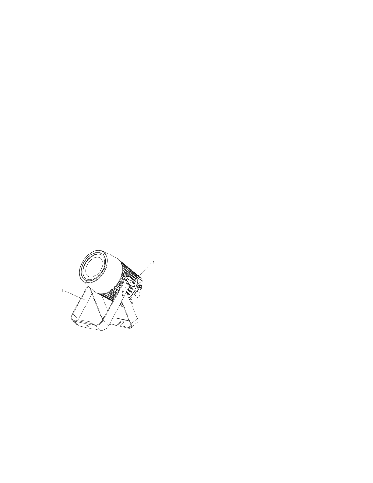
MOUNTING
PROTON IP QW ZOOM may be set up on a solid and even
surface. The unit can also be mounted upside down to a cross
arm. For fixing, stable mounting clips are required. The mounting place must be of sufficient stability and be able to support a
weight of 10 times of the unit’s weight.
When carrying out any installation, always comply scrupulously with all the regulations (particularly regarding safety) currently in force in the country in which the fixture’s being used.
• Install the projector at a suitable location by
means of the mounting bracket (1).
• Always additionally secure the projector with the
safety rope from falling down. For this purpose, fas-
-ten the safety rope at a suitable position so that
the maximum fall of the projector will be 20 cm.
• Adjust the projector and use the screw to slightly
release or tighten the locking mechanism of the
bracket if it’s necessary.
Page 8
PROTON IP QW ZOOM
P.
8
ENGLISH VERSION
5. FUNCTIONS & SETTINGS
OPERATION
Connect the supplied main cable to a socket (100-240
VAC-50/60 Hz). Then the unit is ready for operation and
can be operated via a DMX controller or it independently
performs its show program in succession.
To switchoff, disconnect the mains plug from the socket. For
a more convenient operation it is recommended to connect the
unit to a socket wich can be switched on and off via a light switch.
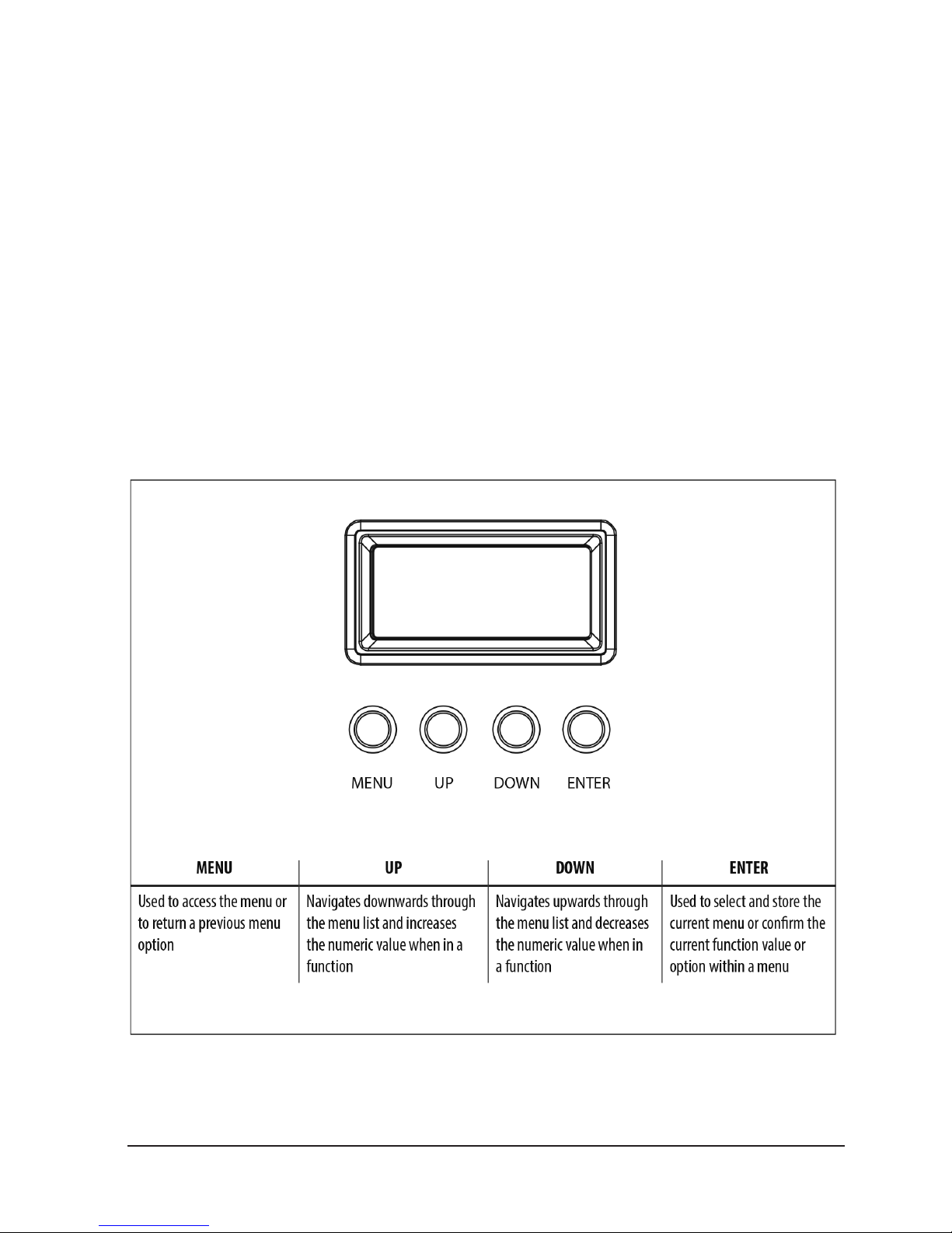
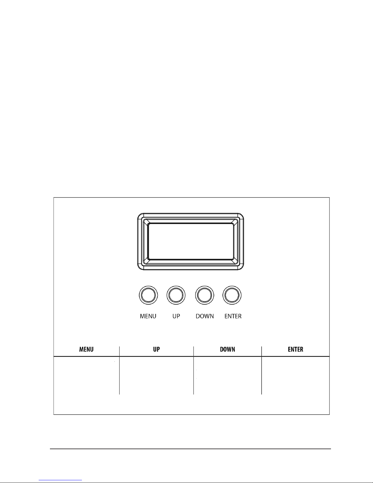
BASIC
Access control panel functions using the four panel buttons located directly underneath the LED Display:
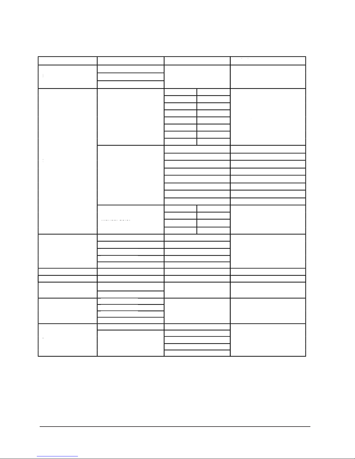
Functions of the buttons
Page 9
PROTON IP QW ZOOM
P.
9
ENGLISH VERSION
MENU
Static
Autoshow
DMX Channel
DMX Address
Master/Slave
Dimmer Mode
White Balance
5 CH
7 CH
11 CH
Fixed Color
Manual Color
Autoshow 1
Autoshow 2
Autoshow 3
Autoshow 4
Autoshow 5
Zoom (0-255)
Offset (0-255)
Master
Slave
Off
Dimmer 1
Dimmer 2
Dimmer 3
Off
Manual
Zoom
Zoom Offset
001
White Presets
G
B
R
GW
BW
RW
W
GBW
GBW
RGW
RGBW
GB
RB
RG
RGB
Default: RGBW
Default: 11ch
Default: 001
Default: RGBW=255
Default: Auto 1, speed=100
Default: 0
Default: Slave
Default: OFF
Default: RGBW=255
GREEN
BLUE
RED
WHITE
(000-255)
(000-255)
(000-255)
(000-255)
(1-100)
(1-100)
(1-100)
(1-100)
(1-100)
2000K
3000K
4000K
5000K
6000K
7000K
8000K
GREEN (125-255)
BLUE (125-255)
RED (125-255)
WHITE (125-255)
Page 10

PROTON IP QW ZOOM
P.
10
ENGLISH VERSION
White Presets Mode
This function allows you to choose preset white color temperatures.
• Press the button MENU until the display shows Static,
then press ENTER.
• Press the UP/DOWN buttons to select White Preset,
then press ENTER.
• Press the UP/DOWN buttons to scroll to the desired pre-
set, then press ENTER.Four selectable dimming curves:
OFF, dimmer 1,2,3 (fast, medium, slow.)
Auto Show
If no DMX control signal is present at the DMX INPUT, the
unit independently runs through its show programme provided that the blackout mode is switched off:
• Press the button MENU so many times until the display
shows Auto Show, then press the button ENTER.
• Press the button UP/DOWN to switch between the show
Auto 1 - Auto 5. The unit will operate in show
mode.
• Using the button UP/DOWN to select the desired run
speed slow-fast 0-100.
• Press the button ENTER to save the setting.
IMPORTANT: Programs Auto 1 - 5 are fully pre-programmed and will not be altered by changes.
Static mode
• The fixture has the ability to accept custom static color
settings. Access these chases via the control panel on the
back of the fixture.
• Press the button MENU so many times until the display
shows Static, then press the button ENTER.
• Select Fixed Color through the buttons UP/DOWN, then
press the button ENTER.
LED Frequency
Fan Mode
Backlight
Key Lock
Information
Reset factory
Default: 1200hz
Default: Auto Speed
Default: ON
Default: ON
600HZ
1200HZ
2000HZ
4000HZ
25kHZ
Auto Speed
High Speed
ON
10S
20S
30S
ON
OFF
Fixture Hours
Version
UID
YES
NO
(9999H)
(V1.0)
15D00207****
Page 11

PROTON IP QW ZOOM
P.
11
ENGLISH VERSION
• Set the colors R , G , B, W, GB, RB, RG, ,RGB, RW, GW, BW,
RGW, RBW, GBW, RGBW, through the buttons UP/DOWN,
then press the button ENTER.
• Press the MENU button to go back or to meet the waiting
time to exit the setup menu.
Manual mode
This mode allows to combine the colors red, green, blue
and white (R, G, B, W).
• Press the button MENU so many times until the display
shows Static, then press the button ENTER. • Select Manual Color through the buttons UP/DOWN, then press the
button ENTER.
• Select the color R, G, B, W through the buttons UP/
DOWN, then press the button ENTER.
• Using UP/DOWN button, selec t the desired color value 000 - 255.
• Press ENTER button to continue to the next color R, G, B,. W.
• Continue until the desired mix is obtained.
• Press the MENU button to go back to the main menu.
Master/slave mode
This mode will allow you to link up the units together without a controller. Choose a unit to function as the Master.
The unit must be the firast unit in line; other units will work
as slave.
• Use standard DMX cables to daisy chain your units together via the DMX connector on the rear of the units. For
longer cable runs we suggest a terminator at the last fixture.
• Set on master fixture the desired program.
• Set the slaves to the same DMX modes.
Linkung
• Connect the DMX OUT of the master unit via 5-pin XLR
cable to the DMX IN of the first slave unit.
• Connect the DMX OUT of the first slave unit to the DMX
Page 12

PROTON IP QW ZOOM
P.
12
ENGLISH VERSION
IN of the second slave unit, etc. until all units are connected
in a chain.
DMX Mode
Press the button MENU so many times until shows 5 Ch, 7
Ch or 11 Ch and press the button ENTER to confirm.
• Press the button UP/DOWN to select the desired DMX
address 001 - 512. Press and hold to scroll quickly. Press
ENTER button to store.
• Press the MENU button to go back to the main menu.
The tables on page 13 indicate the operating mode and
DMX value. EPAR Z1 is equipped with 5-pin XLR connections.
Dmx addressing
This mode allows you to select the starting address for the
EPAR Z1.
• Press the MENU button until DMX Channel is displayed,
then press ENTER.
• Select the DMX starting address using the UP/DOWN
buttons, then press ENTER • Press the MENU button to go
back to the main menu.
The following diagram shows the connection mode:
Page 13

PROTON IP QW ZOOM
P.
13
ENGLISH VERSION
Connection of the dmx line
DMX connection employs IP65 XLR connectors. Use shielded
pair-twisted cables with 120Ω imped- ance and low capacity.
The following diagram shows the connection mode:
ATTENTION
The screened parts of the cable (sleeve) must never be
connected to the system’s earth, as this would cause faulty
fixture and controller operation.
Overlong runs can be necessary to insert DMX level matching amplifier.
For those connections the use of balanced microphone cable is not recommended because it cannot transmit control
DMX data reliably.
- Connect the controller DMX input to the DMX
output of the first unit.
- Connect the DMX output to the DMX input of
the following unit. Connect again the output to the
input of the following unit until all the units are
connected in chain.
- When the signal cable has to run longer distance
is recommended to insert a DMX termination on
the last unit.
CONSTRUCTION OF THE DMX TERMINATION
The termination avoids the risk of DMX 512 signals being
reflected back along the cable when they reaches the end
of the line: under certain conditions and with certain cable
lengths, this could cause them to cancel the original signals.
The termination is prepared by soldering a 120Ω 1/4 W resistor between pins 2 and 3 of the 5-pin male XLR connector, as shown in figure.
Page 14

PROTON IP QW ZOOM
P.
14
ENGLISH VERSION
DMX CONTROL
Dimmer (0-100%)
Green
Blue
White
Red
Zoom
Strobe
Color Presets
Color Function
White Presets
Color macro
Color macro Speed
Dimmer Fade
Percent/SettingValue
11Ch
Function
000-255
000-255
000-255
000-255
000-255
000-255
031-100
101-130
131-200
201-255
000-255
000-010
011-085
086-170
171-255
000-028
029-056
057-084
084-112
113-140
141-168
169-196
197-224
225-255
R 100%, G 0-100% B 0%
R 100-0%, G 100% B 0%
R 0%, G 100% B 0-100%
R 0%, G 100-0% B 100%
R 0-100%, G 0% B 100%
R 100%, G 0% B 100-0%
R 100%, G 0-100% B 0-100%
R 100-0%, G 100-o% B 100%
R 100%, G 100% B 100% W 100%
No function (shutter open)
Strobe effect slow to fast
No function (shitter open)
Random strobe effect slow to fast
No function (shutter open)
No function
Color presets
White presets
Color macro
Determines
Channel 9
Functionality
000-100%
000-100%
000-100%
000-100%
000-100%
000-100%
Auto program 1
Auto program 2
Auto program 3
Auto program 4
Auto program 5 (Auto Program 1-4)
Preset dimmer speed from display menu
0-100%
000-060
061-110
111-160
161-210
211-255
000-195
196-210
211-225
226-240
241-255
000-000
001-255
000-255
2000k --> 3000k
3000k --> 4000k
4000k --> 6000k
6000k --> 8000k
8000k
Color macro speed slow to fast
Page 15

PROTON IP QW ZOOM
P.
15
ENGLISH VERSION
Percent/Setting
Value
5Ch Function
Percent/Setting
Value7Ch
Function
Dimmer
Green
Blue
White
Red
Zoom
Strobe
000-255
000-255
000-255
000-255
000-255
000-030
031-100
101-130
131-200
201-255
No function (shutter open)
Strobe effect slow to fast
No function (shitter open)
Random strobe effect slow to fast
No function (shutter open)
000-100%
000-100%
000-100%
000-100%
000-100%
000-100%000-255
Green
Blue
White
Red
000-255
000-255
000-255
000-255
000-255
000-100%
000-100%
000-100%
000-100%
000-100%
Zoom
Page 16

PROTON IP QW ZOOM
P.
16
ENGLISH VERSION
Dimmer curve Settings
• To enter dimmer mode and choose to simulate different
dimming curves, press the MENU button repeatedly until
the display shows Dimmer Mode, then press ENTER.
• Press the button MENU repeatedly until Dimmer Mode
shows, and press ENTER button to accept.
• Use the button UP/DOWN to select a dimmer curve .
• Press ENTER button to con rm.
Back light
• To activate backlight display press the button MENU so
many times until shows Back Light, and press ENTER
• Press the button UP/DOWN to select On - 10S - 20S - 30S.
Fixture information
Press the MENU button so many times until shows Information, and then press ENTER button. 2. Use UP/DOWN
button to select: Fixture Hours - Version - UID .
- Fixture Hours
This option shows the user the amount of hours
the PROTON IP QW ZOOMhas been in use
throughout its lifetime. Select Fixture Hours.
- Version
This option shows the user the software version
currently installed in the unit. Select Version.
Led frequency
• To adjust the frequency of the LEDs, press the MENU but-
ton repeatedly until the display shows LED Frequency, and
then press the ENTER button.
• Select the frequency 600 Hz - 25 KHz using the UP/
DOWN buttons,then confirm with ENTER.
Key lock
• The password to unlock access to menu changes is this key
sequence: UP + DOWN + UP + DOWN (followed by ENTER).
Fan mode
To set the rotation speed of the fans refer to the following guide:
• Press the MENU key repeatedly until the display shows
Fan Mode, then press the button ENTER.
• Select by pressing UP/DOWN one of the following options: Auto - High. It is possible choose the speed of
rotation of the fans from: fast High and automatic Auto.
• Press the MENU button to go back or wait a few seconds
to exit the setup menu.
White balance
Enter the White balance to adjust the Red, Green, Blue and
White values to set the white balance. • Press the button
MENU so many times until shows White Balance
• Select the color R, G, B, W through the buttons UP/
DOWN, then press the button ENTER.
• Using UP/DOWN button, select the desired color value 125-255.
• Press ENTER button to continue to the next color R, G, B, W.
• Continue until the desired mix is obtained.
• Press the MENU button to go back to the main menu.
Page 17

PROTON IP QW ZOOM
P.
17
ENGLISH VERSION
Page 18

PROTON IP QW ZOOM
P.
18
VERSION ESPAÑOL
1. DESCRIPCIÓN
Proton IP QW Zoom es un bañador profesional para exteriores que cuenta con 1 LED RGBW de 60W y un zoom motorizado de 6º-23º. Con PWM ajustable, función que ajusta
la frecuencia de refresco para poder trabajar realmente
sin parpadeo, y un control de balance de blanco incorporado, que permite variar la temperatura color entre 2000 y
8000K, el equipo es ideal para broadcasting. Proton IP QW
Zoom cuenta, además, con un dimmer con cuatro curvas de
dimmeo, mezcla de color RGBW interna, macros de color y
un display OLED con una interface amigable y potente. Por
último, gracias a su rating IP65, el equipo es ideal para su
uso en exteriores.
ESPECIFICACIONES
Fuente & Óptica
• Fuente de luz: 1 LED RGBA de 60W
• Vida útil promedio: 50.000 horas
• Zoom motorizado: 6º-23º
Datos fotométricos
• Ángulo de haz de 6º: 3.034 lux @ 5m (16 ft.)
• Ángulo de haz de 23º: 212 lux @ 5m (16 ft.)
Efectos & Funciones
• Tecnología LED de cuatro colores: Mezcla RGBW
suave sin sombras multicolor
• Macros de color y efecto arcoiris
• Dimmer: 0-100% general & para todos los colores
• 4 curvas de dimmeo
• Efecto estrobo: 1-30 Hz
• Efecto pulse
• PWM ajustable: 600/1200/2000/4000 Hz o 25KHz
• Control integrado de balance de blanco
• Gel Frame incluido
• Diseño ultra-resistente y funcionamiento silencioso
• Control
• Canales DMX: 5/7/11
• Modos de operación: DMX, Maestro/Esclavo,
Automático & colores estáticos
• Eléctrico
• Rango de voltaje de entrada: AC100–240V, 50-60Hz
• Consumo de potencia: 89W
• 110V: Hasta 12 unidades
• 220V: Hasta 22 unidades
• Físico
• Certificación IP65
• Display OLED
• Conectores DMX: 2 conectores XLR-5 IP65 de
Entrada/Salida
• Conectores de alimentación Powercon® IP65
de Entrada/Salida
• Dimensiones: 347x260x265 mm. / 13,7x10x10,4 pulg.
• Peso: 5,5 Kg. / 12 Lbs.
Page 19

PROTON IP QW ZOOM
P.
19
VERSION ESPAÑOL
2. SEGURIDAD- ATENCIÓN
1. Este equipo cumple con las Directivas de la Comu ni dad Europea y, por lo tanto, cuenta con certificación CE.
2. El equipo funciona con un voltaje de entrada de
230V~. Para su instalación, póngase en contacto
con un profesional calificado. Para evitar el riesgo
de shock eléctrico, no introduzca modificaciones no
autorizadas en el equipo.
3. El equipo requiere de un sistema de suministro eléc trico con puesta a tierra (equipo clase I, norma IEC
60598-1). A su vez, se recomienda proteger los ca bles de alimentación de los contactos indirectos y
cortocircuitos mediante el uso de interruptores dif erenciales del tamaño adecuado.
4. La instalación eléctrica debe realizarla un electri cista certificado. Procure que el voltaje y la fre cuencia coincidan con los requeridos por la unidad.
5. La unidad está diseñada para uso profesional. No
es de uso residencial.
6. Procure no utilizar el equipo bajo las siguientes condiciones:
- En lugares proclives a vibraciones y sacudidas.
- En lugares con temperatura superior a 40°C.
7. Evite que líquidos inflamables, objetos de metal o
agua entren en contacto con el equipo.
8. No desarme o modifique el equipo.
9. El mantenimiento o reparación del equipo deben
ser realizados por personal calificado. Pónganse
en contacto con el servicio técnico autorizado
más cercano o directamente con su proveedor.
10. Con el fin de respetar el medio ambiente, procure
desechar la unidad en la planta de reciclado más cercana.
11. La garantía no cubre daños provocados por el
uso inapropiado del equipo. El uso inadecuado
del equipo puede ocasionar quemaduras, corto circuitos, shock eléctrico, etc.
12. Desconecte el equipo del suministro eléctrico an t es de realizar cualquier tarea de limpieza o mantenimiento.
13. Procure utilizar un cable de seguridad para afirmar
la instalación. Al utilizar la unidad, cumpla en todo
momento con las regulaciones (especialmente de
seguridad) actualmente vigentes en su país.
14. Instale el equipo en una zona con ventilación.
15. Mantenga cualquier tipo de material inflamable
lejos de la unidad.
16. Reemplace la cubierta, los lentes o la luz ultravio leta si se dañan y comprometen el óptimo funcion amiento del equipo.
17. Reemplace la lámpara de LED si se daña o sufre
deformación por el calor.
18. No mire de forma directa hacia la fuente de luz
cuando el equipo esté encendido. La luz puede
generar convulsiones en las personas fotosensiti vas o con epilepsia.
19. No toque el equipo durante su funcionamiento ya
que su temperatura puede ser muy elevada.
QUE VIENE DENTRO
• PROTON IP QW ZOOM - Cable de Alimentación
• Manual del USUARIO
Page 20

PROTON IP QW ZOOM
P.
20
VERSION ESPAÑOL
3. LIMPIEZA Y MANTENIMIENTO
• Asegúrese de que no haya personas ajenas a la in-
stalación al momento de fijar el equipo.
• Apague el quipo, desconéctelo de la corriente
eléctrica y aguarde a que se enfríe antes de re alizar cualquier tarea de mantenimiento.
• Ajuste bien todos los tornillos que se utilicen para
la instalación del equipo y procure que no mues tren signos de corrosión.
• La cubierta, las herramientas de fijación y los pun-
tos de instalación (cielos rasos, suspensiones y sis
temas de truss) deben estar libres de deformaciones.
• Conserve los cables principales en buenas condi-
ciones. Reemplácelos de forma inmediata si detec ta algún problema.
• Para garantizar el óptimo desempeño del equi-
po, es indispensable limpiar el frente con frecuen cia para remover impurezas causadas por el exce so humo, polvo u otras partículas. Antes de limpi arlo, desconecte el equipo de la corriente eléctri ca. Utilice un paño suave humedecido con un de
tergente suave. Luego seque el frente con cuidado.
Para otras partes del equipo solo emplee un paño
suave y limpio. No utilice ninguna clase de líquidos
ya que podrían filtrarse en el equipo y causar
daños severos.
SUSTITUCIÓN DEL FUSIBLE
1. Extraiga la tapa de seguridad con un destornillador.
2. Sustituya el fusible quemado por uno nuevo del
mismo tipo (T2A-250V).
3. Vuelva a colocar la tapa de seguridad y conecte el equipo
Page 21

PROTON IP QW ZOOM
P.
21
VERSION ESPAÑOL
RESOLUCIÓN DE PROBLEMAS
El equipo no ilumina
PROBLEMAS POSIBLES CAUSAS SOLUCIÓN
Poca intensidad de luz
El equipo no se enciende
El equipo no responde al controlador DMX
- Falta de suministro eléctrico
- Dimmer con valor 0
- Colores con valor 0
- LED agotada
- Tablero LED defectuoso
- Verifique el voltaje del suministro eléctrico.
- Aumente el valor de los canales de dimmer.
- Aumente el valor de los canales de color.
- Sustituya la lámpara.
- Sustituya el tablero.
- Dirección DMX errónea
- Cables DMX defectuoso
- Rebote de señal
- Falta de suministro eléctrico
- Cable suelto o defectuoso
- Suministro eléctrico defectuoso
- Lentes sucios
- Lentes mal alineados
- Modifique la dirección DMX en el panel de control.
- Sustituya el cable DMX.
- Instale un terminador.
- Asegúrese de la presencia de corriente en las tomas.
- Verifique el estado del cable.
- Verifique la instalación eléctrica.
- Limpie los lentes del equipo
- Reinstale los lentes
Page 22

PROTON IP QW ZOOM
P.
22
VERSION ESPAÑOL
4. DESCRIPCIÓN DEL EQUIPO
Panel
1. PERILLA DE FIJACIÓN para la abrazadera.
2. ABRAZADERA DE MONTAJE
3. ENTRADA DMX (XLR-5)
A) A tierra
B) DMX -
C) DMX +.
4. SALIDA DMX (XLR-5)
A) A tierra
B) DMX -
C) DMX +.
5. PANEL DE CONTROL con pantalla y cuatro te-
clas que brindan acceso a las funciones disponibles.
6. ENTRADA DE POTENCIA: Clavija de alimentac-
ión (100-240 V, 50/60 Hz) mediante el uso del ca ble correspondiente.
7. SALIDA DE POTENCIA (PowerCon IP65) para
conectar a la próxima unidad enlazada en una cadena.
8. ORIFICIO PARA EL CABLE DE SEGURIDAD
9. VÁLVULA GORE.
Page 23

PROTON IP QW ZOOM
P.
23
VERSION ESPAÑOL
MONTAJE
PROTON IP QW ZOOM se puede instalar sobre una superficie plana y también de forma colgante. Para la instalación
es necesario contar con sujetadores de montaje. Verifique
que el punto de instalación cuente con la estabilidad necesaria y que pueda tolerar 10 veces el peso del equipo.
Asegúrese de cumplir con todas las regulaciones locales
(especialmente aquellas referidas a la seguridad) al momento de realizar el montaje.
• Instale el proyector en un lugar apropiado medi
ante la abrazadera de montaje.
• Siempre utilice un cable de seguridad para afirmar
la parte inferior de la unidad al punto de sujeción y
evitar que el equipo sufra una caída de más de 20 cm.
• Asegure el proyector y utilice la perilla de fijación
para ajustar o desajustar el sistema de cierre de la
abrazadera en caso de que sea necesario.
Page 24
PROTON IP QW ZOOM
P.
24
VERSION ESPAÑOL
5. FUNCIONES Y AJUSTES
OPERACIÓN
Una vez conectado el cable de alimentación incluido (100240 VAC, 50/60 Hz), el equipo estará listo para operar. El
usuario podrá utilizarlo mediante un controlador DMX o
bien podrá ejecutar los programas de forma independiente.
Para apagar el equipo, desconéctelo del suministro eléctrico. Se recomienda conectar el equipo a una red con interruptor para agilizar el encendido y apagado.
PANEL DE CONTROL
Acceda a las funciones del panel de control a través de las
cuatro teclas ubicadas debajo de la pantalla LED.
Functions of the buttons
Selecciona la función
deseada o regresa al
menú anterior
Se desplaza hacia arriba
o aumenta el valor de la
selección.
Se desplaza hacia abajo
o disminuye el valor de la
selección.
Selecciona y almacena la
función deseada o confirma el valor elegido.
FUNCIONES DE LAS TECLAS
Page 25

PROTON IP QW ZOOM
P.
25
VERSION ESPAÑOL
MENU
Static
Autoshow
DMX Channel
DMX Address
Master/Slave
Dimmer Mode
White Balance
5 CH
7 CH
11 CH
Fixed Color
Manual Color
Autoshow 1
Autoshow 2
Autoshow 3
Autoshow 4
Autoshow 5
Zoom (0-255)
Offset (0-255)
Master
Slave
Off
Dimmer 1
Dimmer 2
Dimmer 3
Off
Manual
Zoom
Zoom Offset
001
White Presets
G
B
R
GW
BW
RW
W
GBW
GBW
RGW
RGBW
GB
RB
RG
RGB
Defectot: RGBW
Defecto: 11ch
Valor por defectot: 001
Defecto: RGBW=255
Defectot: Auto 1, speed=100
Defecto: 0
Defecto: Slave
Defecto OFF
Defecto: RGBW=255
GREEN
BLUE
RED
WHITE
(000-255)
(000-255)
(000-255)
(000-255)
(1-100)
(1-100)
(1-100)
(1-100)
(1-100)
2000K
3000K
4000K
5000K
6000K
7000K
8000K
GREEN (125-255)
BLUE (125-255)
RED (125-255)
WHITE (125-255)
Page 26

PROTON IP QW ZOOM
P.
26
VERSION ESPAÑOL
Modo Preajustes Blanco
Esta función le permite seleccionar los preajustes de temperatura del color blanco.
• Presione la tecla MENU hasta visualizar Static.
• Oprima ENTER para acceder.
• Utilice las teclas UP o DOWN hasta visualizar
White Preset.
• Oprima ENTER para acceder.
• Utilice las teclas UP o DOWN para seleccionar el
preajuste deseado.
• Confirme la selección con la tecla ENTER.
Programas automáticos
En caso de no haber señal DMX, utilice uno de los cinco
programas incorporados (siempre que el modo blackout
esté desactivado).
• Presione la tecla MENU hasta visualizar Auto Show.
• Oprima ENTER para acceder.
• Utilice las teclas UP o DOWN para seleccionar el
programa (Auto 1-5).
• Confirme la selección con la tecla ENTER.
• Utilice las teclas UP o DOWN para seleccionar la
velocidad del programa (0-100 de lenta a rápida).
• Confirme la selección con la tecla ENTER.
Observación: Los programas automáticos están preprogramados y no es posible modificar sus parámetros.
Modo estático
Regule de forma personalizada los colores estáticos. Accede a esta opción desde el panel de control ubicado en la
parte trasera del equipo.
• Presione la tecla MENU hasta visualizar Static.
• Oprima ENTER para acceder.
LED Frequency
Fan Mode
Backlight
Key Lock
Information
Reset factory
Defecto: 1200hz
Defecto: Auto Speed
Defecto: ON
Defecto: ON
600HZ
1200HZ
2000HZ
4000HZ
25kHZ
Auto Speed
High Speed
ON
10S
20S
30S
ON
OFF
Fixture Hours
Version
UID
YES
NO
(9999H)
(V1.0)
15D00207****
Page 27

PROTON IP QW ZOOM
P.
27
VERSION ESPAÑOL
• Utilice las teclas UP o DOWN hasta visualizar
Fixed Color.
• Oprima ENTER para acceder.
• Utilice las teclas UP o DOWN para seleccionar en tre R , G , B, W, GB, RB, RG, RGB, RW, GW, BW,
RGW, RBW, GBW, RGBW.
• Confirme la selección con la tecla ENTER.
• Presione la tecla MENU para volver al menú anterior o para salir.
Modo manual
Genere combinaciones de los colores rojo, verde, azul y
blanco (r, g, b, w).
• Presione la tecla MENU hasta visualizar Static.
• Oprima ENTER para acceder.
• Utilice las teclas UP o DOWN hasta visualizar
Manual Color.
• Oprima ENTER para acceder.
• Utilice las teclas UP o DOWN para seleccionar r, g, b o w.
• Confirme la selección con la tecla ENTER.
• Utilice las teclas UP o DOWN para seleccionar el
valor del color deseado (000-255).
• Oprima ENTER para continuar con el siguiente color.
• Continúe con estos pasos hasta obtener la mezcla
de colores deseada.
• Presione la tecla MENU para volver al menú ante
rior o para salir.
Modo maestro/esclavo
Con este modo podrá enlazar varios equipos en serie sin
necesidad de un controlador. La primera unidad funcionará
como equipo maestro y el resto, como esclavos.
• Utilice un cable DMX para enlazar los equipos en tre sí, a través del conector DMX ubicado en la
parte trasera de las unidades. Cuando el cable DMX debe
recorrer largas distancias se recomienda el uso de un terminador en la última unidad de la cadena.
Page 28

PROTON IP QW ZOOM
P.
28
VERSION ESPAÑOL
• Configure el programa deseado en el equipo maestro.
• Configure el mismo modo DMX en los equipos esclavos.
Linking
Siga los siguientes pasos para enlazar unidades entre sí:
• Conecte un extremo de un cable XLR-5 a la sali da DMX del equipo maestro y el otro extremo a la
entrada DMX del primer equipo esclavo.
• Conecte la salida DMX del primer equipo esclavo
a la entrada DMX del segundo equipo esclavo. Re itere este paso hasta tener todas las unidades enlazadas.
Modo dmx
PROTON IP QW ZOOM cuenta con diversas opciones
para la configuración DMX.
• Presione la tecla MENU para activar la configura ción DMX deseada (5CH, 7CH o 11CH).
• Confirme la selección con la tecla ENTER.
• Utilice las teclas UP o DOWN para seleccionar el
valor deseado (001-512).
• Confirme la selección con la tecla ENTER.
• Presione la tecla MENU para volver al menú ante
rior o para salir.
Nota: Los cuadros de la página 13 muestran los modos
de funcionamiento y los valores DMX. PROTON IP QW
ZOOM viene equipado con conectores XLR de cinco pines.
Dirección dmx
Utilice esta opción para seleccionar la dirección de inicio
de PROTON IP QW ZOOM.
• Presione la tecla MENU hasta visualizar DMX Channel.
• Oprima ENTER para acceder.
• Utilice las teclas UP o DOWN para seleccionar la
dirección de inicio.
• Confirme la selección con la tecla ENTER.
• Presione la tecla MENU para volver al menú ante rior o para salir.
Conexión DMX
La conexión DMX requiere conectores XLR IP65. Utilice
cables tipo par trenzado apantallados con impedancia de
120Ω y baja capacidad.
El siguiente diagrama ilustra el modo de conexión:
ENTRADA DMX
XLR MACHO
SALIDA DMX
XLR HEMBRA
Pin 1: A tierra
Pin 2: - Negativo
Pin 3: + Positivo
Pin 4: Sin función
Pin 5: Sin función
Page 29

PROTON IP QW ZOOM
P.
29
VERSION ESPAÑOL
OBSERVACIÓN:
La malla protectora del cable no debe estar en contacto
con la instalación a tierra, ya que puede generar desperfectos en la unidad y su funcionamiento.
No se recomienda el uso de un cable de micrófono equilibrado, ya que no transmite datos de control DMX de manera
fiable.
• Conecte la entrada DMX del controlador a la sali
da DMX de la primera unidad.
• Conecte la salida DMX a la entrada DMX de la
siguiente unidad. Reitere este paso hasta conectar
todas las unidades deseadas.
• Cuando el cable DMX debe recorrer largas dis tancias se recomienda el uso de un terminador en
la última unidad de la cadena.
TERMINADOR DMX
El uso de un terminador ayudará a prevenir la posible pérdida de señal DMX 512 sobre el final de una cadena de
equipos. Bajo ciertas circunstancias y con determinadas
extensiones de cables, esto podría causar que se cancele
la señal original.
El terminador es básicamente un conector XLR con una
resistencia de 120 Ω ¼ W entre los pines 2 y 3 del conector
macho, como indica la imagen a continuación.
Page 30

PROTON IP QW ZOOM
P.
30
VERSION ESPAÑOL
CUADRO DE CANALES DMX
Dimmer (0-100%)
Verde
Azul
Blanco
Rojo
Zoom
Estrobo
Preajustes de color
Función de color
Preajustes Blancos
Color macro
Velocidad de macro color
Fade de dimmer
Porcentaje/ AjustesValor
11Ch
Función
000-255
000-255
000-255
000-255
000-255
000-255
031-100
101-130
131-200
201-255
000-255
000-010
011-085
086-170
171-255
000-028
029-056
057-084
084-112
113-140
141-168
169-196
197-224
225-255
R 100%, G 0-100% B 0%
R 100-0%, G 100% B 0%
R 0%, G 100% B 0-100%
R 0%, G 100-0% B 100%
R 0-100%, G 0% B 100%
R 100%, G 0% B 100-0%
R 100%, G 0-100% B 0-100%
R 100-0%, G 100-o% B 100%
R 100%, G 100% B 100% W 100%
Sin función (shutter abierto)
Efecto estrobo (velocidad creciente)
Sin función (shutter abierto)
Efecto estrobo aleatorio (velocidad creciente)
Sin función (shutter abierto)
Sin función
Preajustes de color
Preajustes de blanco
Macro de color
Determina la funcionalidad del canal 9
000-100%
000-100%
000-100%
000-100%
000-100%
000-100%
Programa automático 1
Programa automático 2
Programa automático 3
Programa automático 4
Programa automático 5 (programas 1-4)
Velocidad de dimmer preestablecida desde la
pantalla
000-060
061-110
111-160
161-210
211-255
000-195
196-210
211-225
226-240
241-255
000-000
001-255
000-255
2000k --> 3000k
3000k --> 4000k
4000k --> 6000k
6000k --> 8000k
8000k
Velocidad creciente
Page 31

PROTON IP QW ZOOM
P.
31
VERSION ESPAÑOL
Porcentaje/ Ajustes
Valor
5Ch
Función
Porcentaje/ Ajustes
Valor7Ch
Función
Dimmer
Verde
Azul
Blanco
Rojo
Zoom
Estrobo
000-255
000-255
000-255
000-255
000-255
000-030
031-100
101-130
131-200
201-255
Sin función (shutter abierto)
Efecto estrobo (velocidad creciente)
Sin función (shutter abierto)
Efecto estrobo aleatorio (velocidad creciente)
Sin función (shutter abierto)
000-100%
000-100%
000-100%
000-100%
000-100%
000-100%000-255
Verde
Azul
Blanco
Rojo
000-255
000-255
000-255
000-255
000-255
000-100%
000-100%
000-100%
000-100%
000-100%
Zoom
Page 32

PROTON IP QW ZOOM
P.
32
Curva de dimming
• Presione la tecla MENU hasta visualizar Dimmer Mode.
• Oprima ENTER para acceder.
• Utilice las teclas UP o DOWN para seleccionar cur
va del dimmer entre OFF, Dimmer1, Dimmer2 y Dimmer3.
• Confirme la selección con la tecla ENTER.
Luz de fondo
• Presione la tecla MENU hasta visualizar Back Light.
• Oprima ENTER para acceder.
• Utilice las teclas UP o DOWN para seleccionar en
tre On, 10s, 20s y 30s.
• Confirme la selección con la tecla ENTER.
Información del equipo
• Presione la tecla MENU hasta visualizar Information.
• Oprima ENTER para acceder.
• Utilice las teclas UP o DOWN para seleccionar en
tre Fixture Hours, Version y UID.
• Confirme la selección con la tecla ENTER.
Fixture Hours: Indica el total de horas de funcion
amiento del Proton IP QW Zoom.
Version: Indica la versión del software instalada en el equipo.
Frecuencia de led
• Presione la tecla MENU hasta visualizar LED Frequency.
• Oprima ENTER para acceder.
• Utilice las teclas UP o DOWN para seleccionar en
tre 600 Hz-25 KHz.
• Confirme la selección con la tecla ENTER.
Bloqueo de teclas
• La contraseña para de blo-
quear el acceso al menú es la
siguiente combinación de teclas: UP
+DOWN+UP+DOWN+ENTER.
Modo de ventilador
• Presione la tecla MENU hasta visualizar Fan Mode.
• Oprima ENTER para acceder.
• Utilice las teclas UP o DOWN para seleccionar en
tre Auto y High.
• Confirme la selección con la tecla ENTER.
• Presione la tecla MENU para volver al menú ante
rior o para salir.
Balance de blancos
Regule los valores de los colores rojo, verde, azul y blanco
para configurar el balance de blancos.
• Presione la tecla MENU hasta visualizar White Balance.
• Oprima ENTER para acceder.
• Utilice las teclas UP o DOWN para seleccionar en
tre R, G, W y W.
• Oprima ENTER para acceder.
• Utilice las teclas UP o DOWN para establecer el
valor deseado entre 125-255.
• Oprima ENTER para continuar con el siguiente
color y hasta obtener la mezcla deseada.
• Presione la tecla MENU para volver al menú ante rior o para salir.
Page 33

PROTON IP QW ZOOM
P.
33
Distancia proyectada
(metros)
Luminosidad (lux)
Ángulo de haz: 6°
Ángulo de haz: 23°
Distancia proyectada
(metros)
Luminosidad (lux)
Page 34

FOR MORE INFO ON THIS PRODUCT PLEASE CHECK WWW.TEC-SHOW.COM /
PARA MAS INFORMACION SOBRE ESTE PRODUCTO VISITE WWW.TEC-SHOW.COM
 Loading...