

Page 1
P. 1
- Neo Nexu s Dual Split RDM
USER MANUAL / MANUAL DE USUARIO
PLEASE READ THE INSTRUCTIONS CAREFULLY BEFORE USE
POR FAVOR LEA LAS INSTRUCCIÓNES ANTES DE USAR
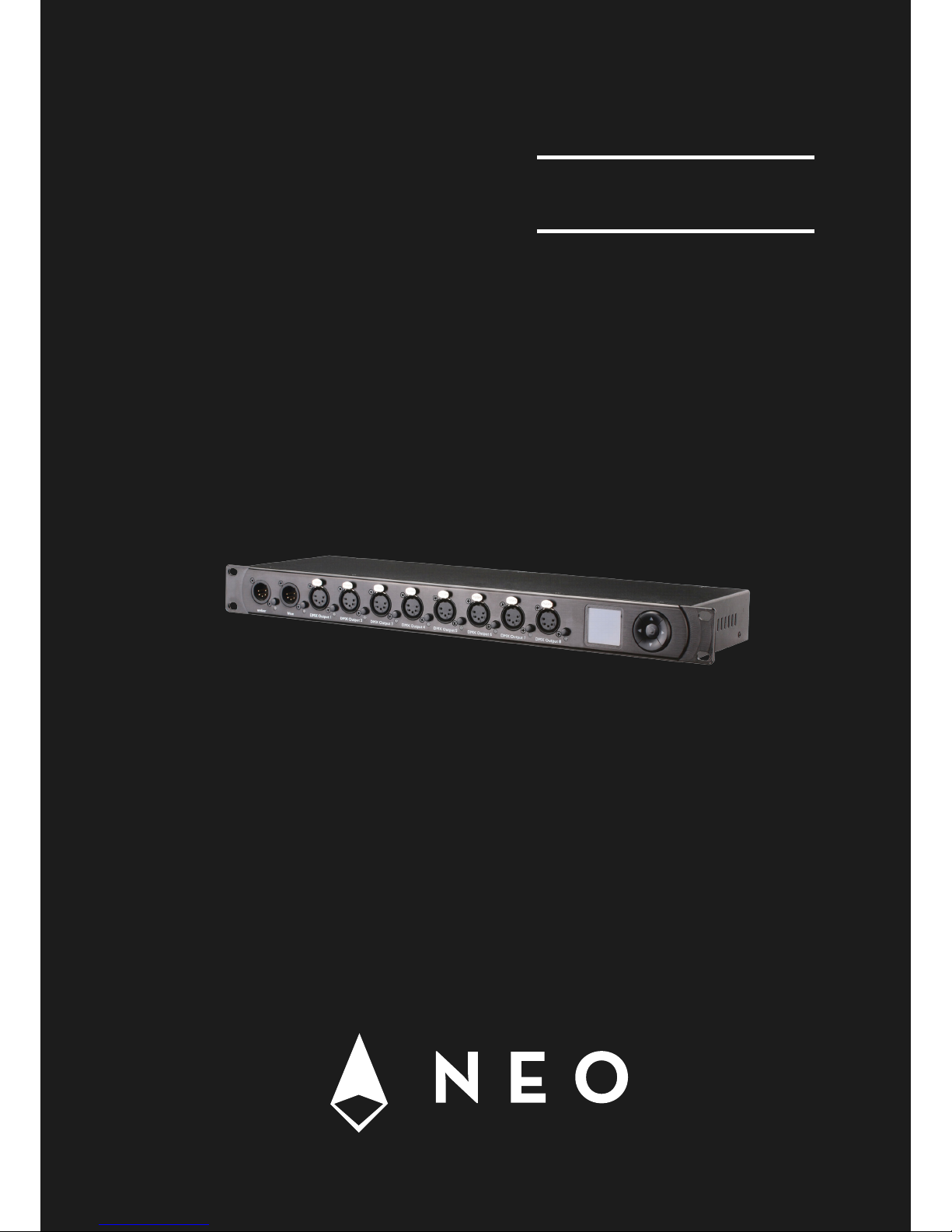
NEXUS
DUAL SPLIT RDM
DMX & RDM Splitter
2 inputs / 8 outputs
Page 2

P. 2
Neo Nexu s Dual Split RDM -
1. OVERVIEW
English version
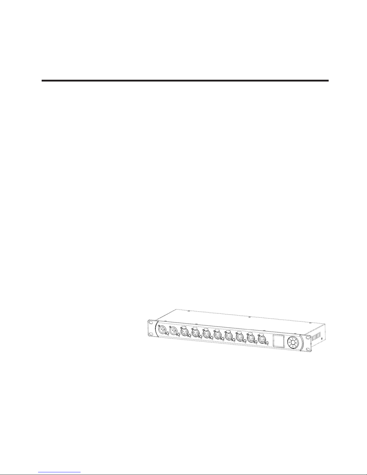
Nexus Dual Split RDM
DMX & RDM Splitter - 2 inputs / 8 outputs
Nexus Dual Split RDM is a DMX & RDM splitter that
features eight outputs, which can be connected to
any of the two inputs. With its 128x128 full color
OLED display, a navigation button and a push button
for each of the signal ports, that are optically isolat-
ed, the conguration of the splitter is quick and easy
despite its versatility. Nexus Dual Split RDM sports an
RGB LED next to each of the signal ports that lets the
user know at a glance the status of the signal at any
given port.
Features
• DMX splitter / booster
• RDM capable (bidirectional)
• 19 inch rack mountable
• 8 output modes
• 2 failure behaviors
• Optically isolated
• Graphical overview of channel values
• Display of the refresh rate
• Can be used as a DMX “decelerator”
• Regenerate / clean DMX signals
• Prevent reection issues
Technical
• Operating temperature: -30ºC~55ºC /
-22ºF~131ºF
• DMX: ANSI E1.11
• RDM: ANSI E1.20
• Neutrik® powerCON input & output
• Electric standard signal ports: EIA-485
Physical
• Dimensions: 136.9x482.6x44.5 mm. /
5.4x19x1.75 in.
• Weight: 2 Kg. / 4.4 Lbs.
Page 3
P. 3
- Neo Nexu s Dual Split RDM
English version
2. INTRODUCTION
Nexus Dual Split RDM is a DMX & RDM splitter provided with eight outputs, which can be connected
to any of the two inputs. Each of its ten signal ports
is optically isolated.
With its 128x128 full color pixels OLED display, a
navigation button and a push button for each of
the signal ports, the conguration of the splitter is
quick and easy to do in spite of the device’s versatility. An RGB LED next to each of the signal ports
lets you know at a glance whether a good signal is
available at any given port.
If you need to know more about the incoming DMX
signal, the OLED display will show you the refresh
rate and the number of received channels when
you push the button next to any of the two inputs.
Furthermore, a graphical overview of the received
channel values is available.
The various output modes of the LF-SP28-3P also
allow for using the device as an accelerator or decelerator.
The Nexus Dual Split RDM is available with 3-pin or
5-pin XLR connectors.
Applications
• Concert lighting
• Live events
• Multimedia shows
• Theaters
• TV studios
• Theme parks
• Architectural lighting
Page 4
P. 4
Neo Nexu s Dual Split RDM -
English version
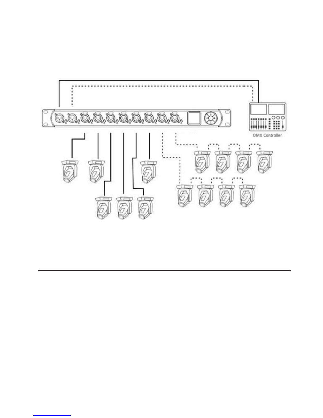
Typical Application
3. UNPACKING
The Nexus Dual Split RDM is packaged in export
cartons. The following items are included:
• Device
• Power cable
• User manual
Page 5

P. 5
- Neo Nexu s Dual Split RDM
English version
4. SAFETY INFORMATION
Consider the following notes mandatory when you
set up, connect and use the Nexus Dual Split RDM.
This product is approved for professional use only,
it is not intended for household usage. Read this
manual before operating the device, follow the
safety precautions closely and pay attention to all
warnings given in this manual.
Use this device only in accordance with local laws
and regulations.
Safety Precautions
• Disconnect the device from the AC power supply before removing any cover or part, including
fuses, even when not in use.
• Ensure that the device is electrically connected
to ground (earth).
• Use only a source of AC power supply that complies with local building and electrical regulations and which has both overload and groundfault (earth fault) protection.
• Before using the device, check that the pow-
er distribution equipment and cables are in
perfect condition and rated for the current
required by all connected devices.
• Isolate the device from power supply immediately if the power cable or the power plug are
in any way damaged, defective or wet, or if they
show signs of overheating.
• Do not expose the device to rain or moisture.
• Do not operate the device if any cover or com-
ponent is missing, damaged or deformed.
• Provide unrestricted airow around the device.
• Do not operate the device if the ambient tem-
perature exceeds 55°C (131°F).
• Do not modify the device in any way not described in this manual.
• Do not attempt to bypass any fuse. Replace any
defective fuse with one of the specied type
and rating only.
• When suspending the device, ensure that the
supporting structure and all hardware used
can hold at least 10 times the weight of all
devices suspended together.
• When suspending the device, install a second-
ary attachment such as a safety cable that is
approved by an oicial body such as, e.g. TÜV
(German Technical Monitoring Association),
a safety attachment for the total weight it
secures. The safety cable must comply with
EN 60598-2-17 section 17.6.6 and be capable of
bearing a static suspended load 10 times the
weight of the device.
• Make sure that any external cover and rigging
hardware is securely fastened.
• Provide an adequate clearance underneath
the work area and a stable platform whenever
installing, servicing or moving an overhead
device.
• Do not use the device in areas where it is exposed to direct sunlight.
• Do not use the device in areas that are consid-
ered to be “highly inammable”.
Page 6
P. 6
Neo Nexu s Dual Split RDM -
English version
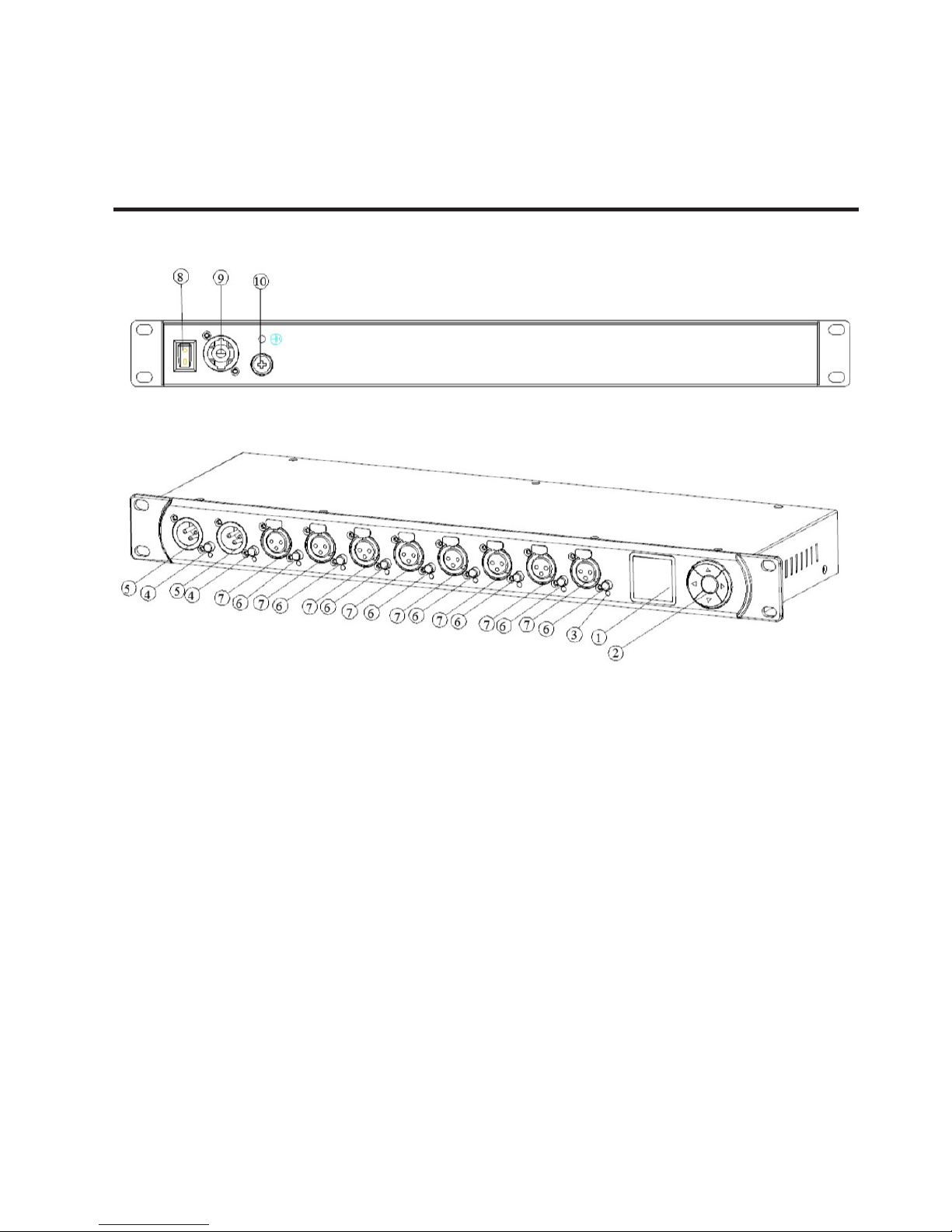
5. DEVICE OVERVIEW
1. OLED display.
2. The navigation buttons. The is primarily used
for selecting menu items by Pressing.
3. RGB LED.
4. Input port buttons [A] and [B]. These push
buttons are used to display detailed status
information of the respective input. An input
port status LED showing essential, basic status
information, is located directly below each of
those buttons.
5. Signal input ports for the universes A and B.
6. Output port buttons [1] – [8]. These push
buttons are used to change to which universe
the respective output is connected. An output
port status LED showing to which universe the
respective output port is currently connected
as well as further status information is located
directly below each of those buttons.
7. Signal output ports 1 – 8.
8. Power switch.
9. PowerCON input socket.
10. Fuse holder.
Page 7
P. 7
- Neo Nexu s Dual Split RDM
English version
6. DMX CONNECTIONS
Mains Connection
The user must supply a suitable power cable. He
may then either hard-wire the power cable to the
building’s electrical installation, providing an easily
accessible power on/o switch close to the device,
or install on the power cable a grounding-type
(earthed) mains plug that is suitable for the local
power outlets, following the power plug manufacturer’s instructions. Consult a qualied electrician,
if you have any doubts about the proper installation.
A blue powerCON cable mount connector must be
used to supply power at the LF-SP28-3P ’s power
input socket.
Depending on the version, the Nexus Dual Split
RDM is equipped with 5-pin or 3-pin XLR connectors.
XLR Connectors
The DMX inputs are fully isolated. All outputs are
isolated transmitters with a bias network for RDM
operation. Each output port is individually optically
isolated, meaning that it is totally isolated from the
other output ports and from the input section.
Warning! For protection against dangerous
electrical shocks, the device must be grounded
(earthed). The local AC power source must be sup-
plied with both overload and ground-fault (earth
fault) protection.
Important! Only attach or remove a powerCON
connector while it is connected to the mains to
apply or cut power in an emergency situation, as
by doing so may cause arcing at the terminals that
will damage the connectors.
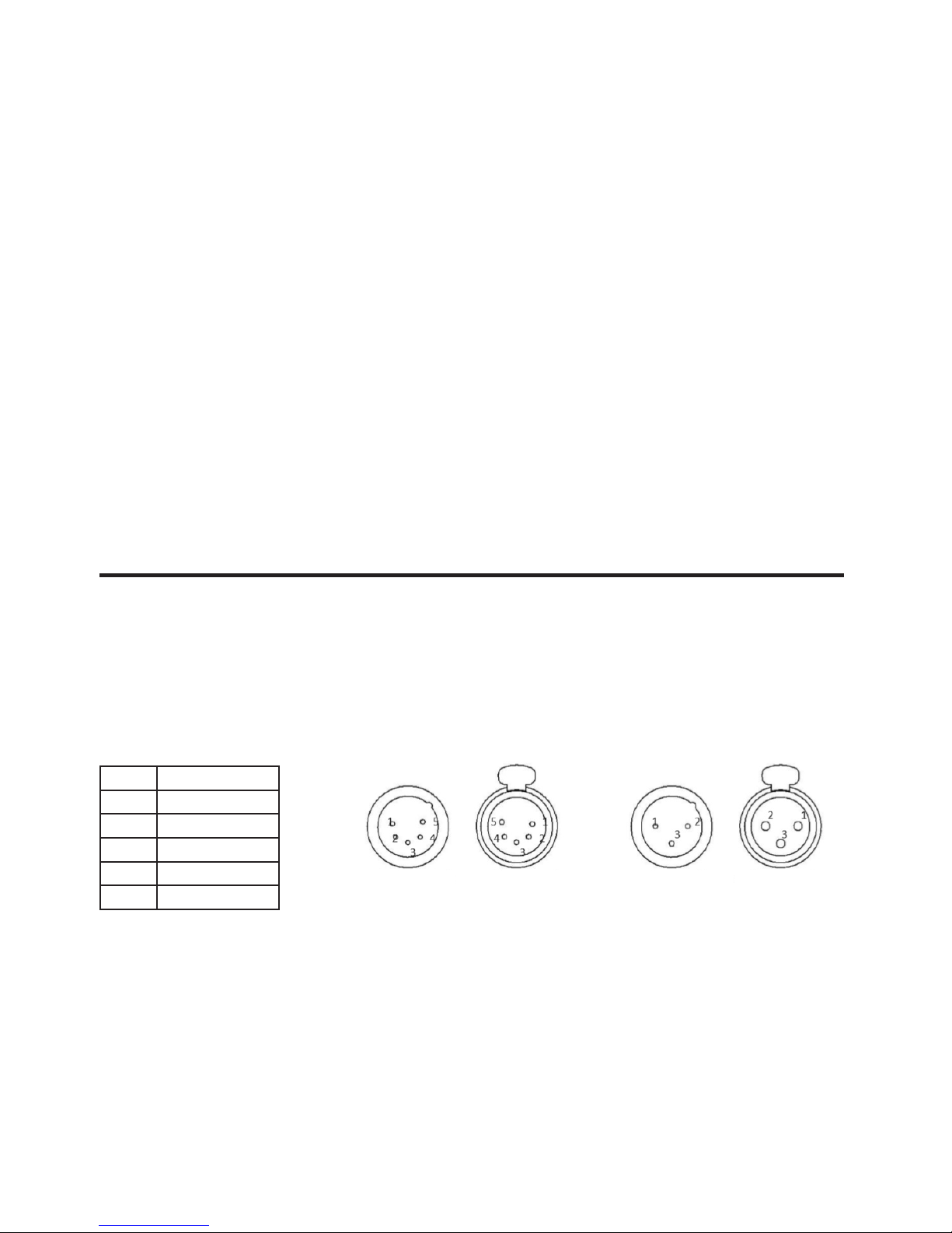
Pin Connection
1 Com
2 Data -
3 Data +
4 Not connected
5 Not connected
5-Pin XLR male
(DMX in)
5-Pin XLR female
(DMX out)
3-Pin XLR female
(DMX out)
3-Pin XLR male
(DMX in)
Page 8
P. 8
Neo Nexu s Dual Split RDM -
English version
7. SETTINGS AND MENU
General Navigation
The navigation buttons is the primary means for
navigating through the menus. Most of the menus
arrange items vertically. In those menus, Press the
down button to select the item below the currently
selected item or Press the up button to select the
item above the currently selected item. In menus
that arrange items horizontally (e.g. text elds), Press
the down button means “to the right” and counter
Press the up button means “to the le”.
Other than that, the right button also functions as a
push button. This button is generally used to conrm
a selection or to navigate to a selected submenu.
This manual will also refer to pushing the right button as “push [OK]” or “push the [OK] button”.
The le button (depicted on page 7), which is generally used to dismiss a selection or to exit a menu.
By keeping the le button pressed for at least two
seconds, you can always navigate to the Home
Screen. From the Home Screen, the menu is
launched by simply pushing the [OK] button.
Below, the following notation is used to describe lo-
cations in the menu: Home > Menu > Sub menu > …
For example, the manual could say “navigate to
Home > Menu > Input A > Mode”. This can be read as
follows:
Keep le button pressed for 2 seconds or pushing
the home button to reach the Home Screen.
Then, press MENU to get to the menu.
Select “Input A” using the up down key and press
enter again to conrm the selection.
Select “Mode” and conrm your selection once
again with the ENTER button.
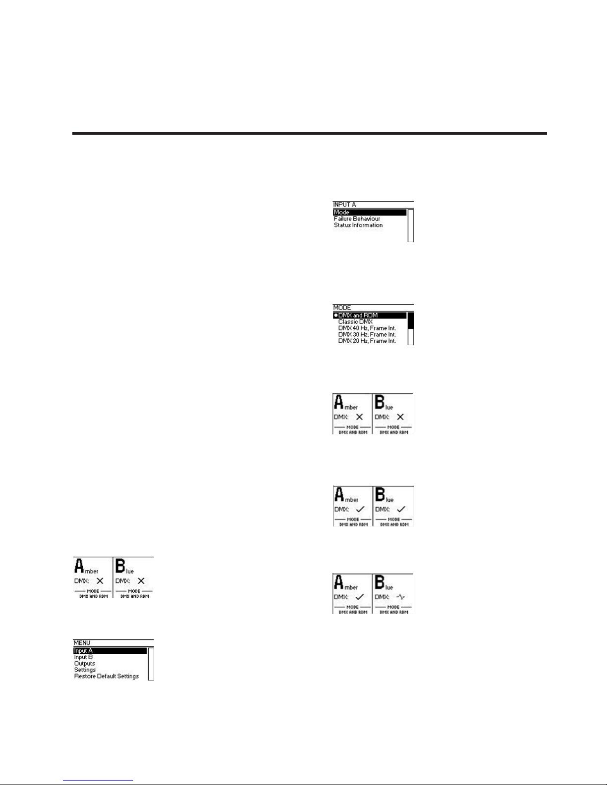
Home Screen
Home Screen indicating that no signal is available on
either input port.
Home Screen indicating that a valid signal is applied
to each of the signal inputs.
Home Screen showing a valid signal on input A and a
disturbed signal on input B.
Page 9

P. 9
- Neo Nexu s Dual Split RDM
English version
The Home Screen (Main Screen) is divided into a le
and a right section. The le section contains information about the signal status of the input A and the
currently active DMX Output Mode of the outputs
connected to input A. The other half of the Home
Screen shows the same information for the input
port B and its connected outputs.
Input/Universe Settings and
Information
The settings for the universe A (B) and its input are
accessible under Home > Menu > Input A (Home >
Menu > Input B). This menu oers the sub menus
“Mode”, “Failure Behaviour” and “Status Informa-
tion”, which are described next.
DMX Mode
The DMX mode of the outputs
connected to universe A (B) can
be selected under Home > Menu
> Input A > Mode (Home > Menu
> Input B > Mode). A mode is activated by selecting
it using the up down button and conrming with the
[OK] button. The currently active mode is agged by
a bullet point on the le side.
The following modes are available:
DMX and RDM
In this mode, any arriving DMX and RDM data is forwarded to the outputs of the corresponding universe
as it arrives at the input. NAVIGATOR DUAL SPLIT
RDM is discoverable via RDM and responds to RDM
packets addressed to the device. For RDM-traic
addressed to devices connected to the outputs of
the universe, the device operates as a bidirectional
RDM-splitter.
DMX and RDM is the default mode which is applied to
both universes when you restore the default settings
as described on manual.
Classic DMX
DMX data is forwarded as it arrives. The splitter is
not discoverable via RDM and does not work as a
bidirectional splitter.
DMX 40 Hz, Frame Int.
This mode sends DMX data with a well-dened
timing characteristic, regardless of the timing of
the received signal. At the cost of a small delay, the
“Frame Integrity” is maintained. This means, that
no partially updated DMX frames are sent out. This
may be important when multi-slot parameters are
in use. The splitter is not discoverable via RDM and
does not work as a bidirectional splitter.
DMX 30 Hz, Frame Int.
As above.
DMX 20 Hz, Frame Int.
As above.
DMX 10 Hz, Frame Int.
As above.
DMX 40 Hz
This mode sends DMX data with a well-dened
timing characteristic, regardless of the timing of
the received signal.
The “Frame Integrity” is not maintained. This
means that partially updated DMX frames may be
sent out. The splitter is not discoverable via RDM
and does not work as a bidirectional splitter.
DMX 30 Hz
As above.
DMX 20 Hz
As above.
DMX 10 Hz
As above.
Page 10

P. 1 0
Neo Nexu s Dual Split RDM -
English version
Failure Behaviour
For each of the two input universes, one of two failure behaviours can be chosen under Menu > Input A
> Failure Behaviour (Home > Menu > Input B > Failure
Behaviour).
The failure behaviour determines how the respective
universe reacts at the occurrence of a failure. Generally, it is considered a failure when no valid DMX
signal is observed at the input for the duration of
one second. If the universe is in DMX and RDM mode
however, it is considered a failure only if neither a
valid DMX frame nor the beginning of an RDM message is observed for one second.
O
No DMX is sent on the outputs. In the modes DMX
and RDM and Classic DMX the outputs continue to
forward whatever arrives at the inputs.
Hold Last Look
The outputs of the universe continue sending out
the last received look. If no data has been received
before, no data is sent to the outputs.
Status Information
Status information about each of the inputs is
accessible under Home > Menu > Input A > Status
Information (Home > Menu > Input B > Status Information). As a shortcut, the button on the le below
the respective input port can also be used to recall
this information. Further details about this menu are
explained on page 14 under DMX Input Monitoring
and Diagnostics.
Output Settings and Information
Linking Outputs to Inputs
Output ports can be linked to
one of the two inputs under
Home > Menu > Output N, where
N stands for the number of the
output. The number of each output is printed on
the le above each XLR output port. As a shortcut,
the button on the le below each output port
(button [1] – button [8]) can be used to access the
same menu.
From the menu depicted above, the navigation
buttons or the button on the le below the output
port can be used to change the universe to which
the output port is connected.
DMX Output Mode
The DMX output mode is congured per universe.
See DMX Mode.
Failure Behaviour
The failure behaviour is congured per universe.
See Failure Behaviour above, under Input / Universe Settings and Information.
Device Settings and Information
Label
The device label can be viewed and edited under
Home > Settings > Label.
1. Using UP and SOWN buttons to choose the
position of text wanted to edit, press ENTER to
conrm.
2. Using UP and SOWN buttons to choose text
wanted to edit, press ENTER to conrm.
3. Cycling setp 1 & setp2 until editing nished
4. Press MENU button, then press ENTER to save
or MENU to discard.
Information
The following information about the device is
available under Home > Menu > Settings > Information.
Page 11

P. 11
- Neo Nexu s Dual Split RDM
English version
Model
The device model is reported as “RDM-SP28” for all
variants of the Nexus Dual Split RDM.
UID (A) and UID (B)
The RDM Unique Identier for each of the universes.
Boot Soware
The full version number of the boot soware.
Firmware
The full version number of the rmware.
Hardware
The hardware revision.
Restore Default Settings
The default settings can be restored under Home
> Menu > Restore Default Settings. In this menu,
you will be asked whether you want to continue
restoring all settings. Push enter to conrm or
menu to abort.
This function will restore all settings to the de-
faults:
- Device label: RDM-SP28
- DMX mode: DMX and RDM (on both universes)
- Failure behaviour: O (on both universes)
- Ports assigned to input A: 1-4
- Ports assigned to input B: 5-8
8. STATUS LEDS
Selected Port
When a port is selected, either with the push
button next to it or via the menu, the port’s status
LED ashes up in the colour of its universe for 0.1
seconds once every 0.2 seconds. The colour of the
universe is amber for the universe A and blue for
the universe B.
Not Selected Port
If a port is not selected, the port’s status LED provides the following information:
• It lights up in the colour of its universe for at
least 50% of the time. Amber for universe A
and blue for universe B.
• It turns black for 0.1 seconds every second, if
at the port no signal is available.
• It turns white for 0.4 seconds once a second, if
the port’s universe has received the command
to “identify” itself via RDM.
• It turns red for 0.1 second every second, when
the port has received a faulty signal. (Input
ports only).
Page 12

P. 12
Neo Nexu s Dual Split RDM -
English version
9. SCREEN SAVER
11. RDM
10. DMX INPUT MONITORING AND DIAGNOSTICS
The OLED display will automatically turn o when
no user input is received for 30 seconds in order
to improve the durability of the product. Once the
display is turned o, it can be turned on again by
pushing any button or navigation buttons.
Nexus Dual Split RDM is discoverable via RDM and
works as an RDM capable, bidirectional splitter,
when the corresponding universe is congured to
the mode “DMX and RDM” (see DMX Mode). When a
dierent mode is selected, the RDM capabilities of
the splitter are disabled for the respective universe.
Page 13

P. 13
- Neo Nexu s Dual Split RDM
English version
12. FIRMWARE UPDATES
Connect dmx able to dmx input A port
Page 14

P. 14
Neo Nexu s Dual Split RDM -
Versión Español
1. DESCRIPCIÓN
Nexus Dual Split RDM
Splitter DMX & RDM - 2 entradas / 8 salidas
Nexus Dual Split RDM es un splitter DMX y RDM que
tiene ocho salidas, las cuales pueden ser conectadas
a cualquiera de las dos entradas que también posee.
Con su pantalla OLED a todo color de 128x128, un
botón de navegación y un botón para cada uno de
los puertos de señal, que están ópticamente aislados, la conguración del divisor es rápida y fácil a
pesar de su versatilidad. Nexus Dual Split RDM tiene
un LEDs RGB junto a cada uno de los puertos de
señal, lo que le permite al usuario saber de un vistazo el estado de la señal en cualquier puerto.
Características
• Splitter DMX
• RDM compatible (bidireccional)
• Rackeable de 19 pulgadas
• 8 modos de salida
• 2 comportamientos de falla
• Opticamente aislados
• Overview gráco de los valores de los canales
• Monitoreo de refresh rate
• Puede ser utilizado como un desacelerador
DMX
• Regeneración / limpieza de señal DMX
• Prevenir problemas de reejo
Técnic a
• Temperatura de operación: -30ºC~55ºC /
-22ºF~131ºF
• DMX: ANSI E1.11
• RDM: ANSI E1.20
• Conectores Neutrik® powerCON de entrada &
salida
• Estándar eléctrico de los puertos de señal:
EIA-485
Físico
• Dimensiones: 136.9x482.6x44.5 mm. /
5.4x19x1.75 in.
• Peso: 2 Kg. / 4.4 Lbs.
Page 15

P. 15
- Neo Nexu s Dual Split RDM
Versión Español
2. INTRODUCCIÓN
Nexus Dual Split RDM es un splitter DMX y RDM que
cuenta con ocho salidas, que pueden conectarse a
cualquiera de las dos entradas. Los diez puertos de
señal se encuentran ópticamente aislados.
A pesar de su versatilidad, la conguración del splitter es rápida y sencilla gracias a su pantalla OLED
color de 128x128 pixeles y a los botones de navegación y pulsadores de cada puerto de señal. Un
LED RGB junto a cada puerto de señal permite que el
usuario compruebe con solo un vistazo si hay buena
señal disponible.
Si desea obtener más información sobre la señal
DMX recibida, basta presionar el botón ubicado junto
a las dos entradas y la pantalla OLED indicará la
frecuencia de actualización y el número de canales
recibidos. A su vez, se encuentra disponible un resumen gráco de los canales recibidos.
Los diversos modos de salida del Navigator Dual
Split RDM permiten utilizar la consola como acelerador o desacelerador. Nexus Dual Split RDM está
disponible con conectores XLR-3 o XLR-5.
Usos
• Iluminación de conciertos
• Espectáculos en vivo
• Espectáculos multimedia
• Tea tros
• Estudios de televisión
• Parques de atracciones
• Iluminación arquitectónica
Page 16

P. 1 6
Neo Nexu s Dual Split RDM -
Versión Español
Conexión habitual
3. CONTENIDO
El equipo se entrega embalado en cajas de
exportación. El contenido incluye:
• Un equipo Nexus Dual Split RDM
• Un cable de alimentación
• Un manual del usuario
Page 17

P. 17
- Neo Nexu s Dual Split RDM
Versión Español
4. INFORMACIÓN DE SEGURIDAD
Procure familiarizarse con las notas a continuación
antes de utilizar, instalar o conectar su Nexus Dual
Split RDM.
Este producto es de uso profesional exclusiva-
mente. No es adecuado para uso doméstico. Lea
atentamente el presente manual, siga las instruc-
ciones de seguridad y preste atención a las advertencias descritas.
Utilice este producto de acuerdo con las leyes y
regulaciones locales.
Medidas de seguridad
• Desconecte el equipo del suministro eléctrico
antes de abrirlo, aunque no esté en uso.
• Procure la conexión a tierra del equipo.
• Utilice solo una fuente de alimentación AC
que cumpla con las normas eléctricas y de
construcción locales y que dispongan tanto de
protección por exceso de consumo como por
fugas a tierra.
• Antes de utilizar el equipo, compruebe que el
rango de voltaje de entrada sea el correcto para
todos los equipos conectados, y que los dispositivos de distribución y el cableado esté en
perfecto estado.
• No utilice el equipo si el cable de alimentación
o su conector están dañados, defectuosos o
húmedos o si muestran algún signo de sobrecalentamiento.
• Mantenga el equipo alejado de la lluvia y la
humedad.
• No utilice el equipo si observa componentes
dañados, deformados o faltantes.
• Instale el equipo en un ambiente con buena
circulación de aire.
• No utilice el equipo si la temperatura ambiente
supera los 55°C (131°F).
• No introduzca modicaciones no autorizadas
en el equipo.
• Reemplace el fusible siempre que sea necesario. Utilice fusibles de repuesto únicamente
del mismo tipo y rango.
• Al suspender la unidad en el aire, procure que
la estructura y los elementos utilizados soporten 10 veces el peso del equipo.
• Al suspender la unidad en el aire, procure
utilizar elementos secundarios de seguridad,
como un cable de seguridad, aprobado por un
organismo ocial (TÜV, por ejemplo). El cable
de seguridad debe cumplir con la norma EN
60598-2-17 sección 17.6.6 y debe soportar 10
veces el peso del equipo sin sufrir deforma-
ciones.
• Asegúrese de que todas las cubiertas externas
y accesorios de suspensión estén rmemente
sujetos.
• Mantenga libre la zona trabajo y procure
utilizar una plataforma estable cuando se
instale, repare o mueva el equipo.
• No utilice el equipo en ambientes expuestos a
la luz solar directa.
• No utilice el equipo en ambiente con elementos altamente inamables.
Page 18

P. 18
Neo Nexu s Dual Split RDM -
Versión Español
5. DESCRIPCIÓN DEL EQUIPO
1. Pantalla OLED
2. Botones de navegación: utilícelos para seleccio-
nar los ítems del menú.
3. LED RGB
4. Botones de puertos de entrada A y B.
Presiónelos para obtener información del estado de las respectivas entradas en más detalle.
Debajo de los botones, se encuentra un LED de
estado del puerto de entrada que brinda información básica y esencial.
5. Puertos de entrada de señal de los universos A y B.
6. Botones de puertos de salida 1-8. Presiónelos
para modicar el universo al cual se conecta
la respectiva salida. Debajo de los botones,
se encuentra un LED de estado del puerto
de salida que indica el universo al cual está
conectada dicha salida y brinda información
adicional del estado.
7. Puertos de salida de señal 1-8.
8. Interruptor de encendido/apagado.
9. Conector powercon de entrada.
10. Fusible.
Page 19

P. 1 9
- Neo Nexu s Dual Split RDM
Versión Español
6. CONEXIÓN DMX
Conexión eléctrica
El usuario debe contar con un cable de alimenta- ción adecuado. Siga las indicaciones del fa-
bricante, impresas en el enchufe, para conectar el
cable directamente a la instalación eléctrica del
edicio, siempre que disponga de un interruptor
de encendido cerca del dispositivo, o instalar un
enchufe con conexión a tierra que sea apto para las
tomas de electricidad locales. Si tiene dudas sobre
la instalación, póngase en contacto con un electri-
cista certicado.
Utilice un cable powerCON azul para alimentar la
entrada de potencia de su Nexus Dual Split RDM.
Según la versión, Nexus Dual Split RDM está disponible con conectores XLR-3 o XLR-5.
Conector XLR
Las entradas DMX están totalmente aisladas. Todas
las salidas son transmisores aislados con una red
de bias para función RDM. Cada puerto de salida
está aislado ópticamente de forma individual por lo
cual se mantiene aislado del resto de los puertos de
salida y de la sección de entrada.
Advertencia Procure la conexión a tierra del equipo para evitar descargas eléctricas. La fuente de
corriente alterna debe contar con protección por
exceso de consumo como por fugas a tierra.
Importante Solo conecte o desconecte los
conectores powerCON para cortar la energía en
situaciones de emergencia, ya que acelera la
formación de arcos en las terminales y daña los
conectores.
Clavija Descripción
1 Tierra
2 Señal -
3 Señal +
4 Sin función
5 Sin función
Conector XLR-5
macho (DMX
entrada)
XLR-5 hembra
(salida DMX)
XLR-3 hembra
(salida DMX)
Conector XLR-3
macho (DMX
entrada)
Page 20

P. 2 0
Neo Nexu s Dual Split RDM -
Versión Español
7. FUNCIONES DEL MENÚ
Navegación general
Los botones de navegación (ver página 7) son el
medio principal para desplazarse por los menús. En
la mayoría de los menús, encontrará los ítems distribuidos de forma vertical. Utilice los botones hacia
arriba y hacia abajo para desplazarse por los diferentes ítems. En los menús de distribución horizontal
(campos de texto, por ejemplo), presione el botón
hacia abajo para desplazarse hacia la derecha y el
botón hacia arriba para desplazarse hacia la izquierda. A su vez, el botón hacia la derecha también
cumple la función de pulsador. Este botón se utiliza
generalmente para conrmar una selección o para
navegar el submenú seleccionado. En el presente
manual también se hace referencia al botón hacia
la derecha como “presione OK” o “presione el botón
OK”. El botón hacia la izquierda (ver página 7) se
utiliza generalmente para descartar una selección o
para salir de un menú.
Si desea navegar por la pantalla principal, mantenga presionado el botón hacia la izquierda por dos
segundos. Desde la pantalla principal, presione el
botón OK para abrir el menú.
Debajo encontrará el formato con el cual se describe
las ubicaciones del menú: Home > Menu > Sub menu
> …
Por ejemplo, es usual que el manual indique “navegue hasta home > Menu > Input A > Mode”. Lo cual
puede leerse de la siguiente manera:
Mantenga presionado el botón hacia la izquierda por
dos segundos o presione el botón home varias veces
hasta llegar a la pantalla principal (o home).
Luego presione MENU para acceder.
Utilice los botones hacia arriba/abajo para seleccio-
nar “Input A” y luego pulse ENTER para conrmar
su selección.
Seleccione “mode” y presione nuevamente ENTER
para conrmar su selección.
Pantalla principal
No se encuentra señal en los puertos de entrada.
Hay señal válida en cada entrada de señal.
Hay señal válida en la entrada A, y señal intermitente
en la entrada B.
Page 21

P. 2 1
- Neo Nexu s Dual Split RDM
Versión Español
La pantalla principal está dividida en sección izquierda y sección derecha. La sección izquierda contiene
información sobre el estado de señal de la entrada
A y sobre el modo de salida DMX actualmente activo
de las salidas conectadas a la entrada A. La sección
derecha muestra la misma información, pero para el
puerto de entrada B y sus salidas conectadas.
Configuración de entrada/
universos e información
Para acceder a la conguración del universo A (y B) y
sus entradas, navegue la ruta Home > Menu > Input
A (Home > Menu > Input B). Dentro de este menú
encontrará los submenús “Mode” (modo), “Failure
Behaviour” (comportamiento ante fallas) y “Status
information” (información de estado) descritos a
continuación.
Modo DMX
Seleccione el modo DMX de las
salidas conectadas al universo A
(o B) por medio de Home > Menu
> Input A > Mode (Home > Menu >
Input B > Mode). Para activar el modo deseado, uti-
lice los botones hacia arriba/abajo y luego presione
el botón OK. El modo activo actualmente es el que
cuenta con una viñeta sobre el margen izquierdo.
El usuario cuenta con los siguientes modos disponibles:
DMX y RDM
Todos los datos DMX y RDM recibidos en la entrada
se reenvían a las salidas de los universos correspondientes. Navigator Dual Split RDM es detectable vía
RDM y responde a paquetes RDM dirigidos al dispositivo. El equipo funciona como un splitter bidireccional para tráco RDM dirigido hacia dispositivos
conectados a las salidas del universo.
DMX y RDM son los modos predeterminados que se
aplican a ambos universos cuando el usuario restablece los valores de fábrica.
DMX clásico
Todos los datos DMX recibidos se reenvían. El splitter no es detectable vía RDM y no funciona como
splitter bidireccional.
DMX 40 Hz, Frame Int.
Bajo este modo el usuario envía datos DMX con
temporización bien denida sin importar el tiempo
de la señal recibida. A expensas de un pequeño
retraso, se mantiene la integridad de cuadro (frame
integrity). En otras palabras, no se envían cuadros
DMX parcialmente actualizados. Esto puede ser de
gran importancia cuando se utilizan parámetros
multisegmentos. El splitter no es detectable vía
RDM y no funciona como splitter bidireccional.
DMX 30 Hz, Frame Int.
Igual que el punto anterior.
DMX 20 Hz, Frame Int.
Igual que el punto anterior.
DMX 10 Hz, Frame Int.
Igual que el punto anterior.
DMX 40 Hz
Bajo este modo el usuario envía datos DMX con
temporización bien denida sin importar el tiempo
de la señal recibida.
No se mantiene la integridad de cuadro (frame integrity). En otras palabras, es posible que se envíen
cuadros DMX parcialmente actualizados. El splitter
no es detectable vía RDM y no funciona como split-
ter bidireccional.
DMX 30 Hz
Igual que el punto anterior.
DMX 20 Hz
Igual que el punto anterior.
DMX 10 Hz
Igual que el punto anterior.
Page 22

P. 2 2
Neo Nexu s Dual Split RDM -
Versión Español
Comportamiento ante fallas
Es posible seleccionar uno de los dos comportamientos ante fallas de cada universo de entrada por
medio de Menu > Input A > Failure Behaviour (Home
> Menu > Input B > Failure Behaviour).
Esta función determina cómo reacciona el universo
en caso de que haya algún error o falla de funcionamiento. Por lo general, se considera falla a la falta
de señal DMX en la entrada durante un segundo. Sin
embargo, si el universo se encuentra en modo DMX
y RDM, se considera falla solo si no se observa un
cuadro DMX válido o el comienzo de un mensaje RDM
durante un segundo.
O
No se envía señal DMX a las salidas. En los modos
DMX y RDM y DMX clásico las salidas continuarán
reenviando los datos que reciban en las entradas
correspondientes.
Hold Last Look (Última señal recibida)
Las salidas del universo continúan enviando la última señal recibida. Si no reciben datos, no se envían
datos a las salidas.
Status Information
Es posible acceder a la información de estado de
cada entrada mediante Home > Menu > Input A >
Status Information (Home > Menu > Input B > Status
Information). A modo de acceso directo, utilice el
botón de la izquierda debajo del puerto de entrada
correspondiente. Para obtener más información
sobre este menú, diríjase a la página 14, bajo el encabezado Monitoreo de entrada DMX y diagnóstico.
Configuración de salida e
información
Enlazar salidas con entradas
Los puertos de salida pueden
enlazarse a uno de las dos
entradas mediante Home > Menu > Output N. En
este caso N sería el número de la salida. El núme-
ro correspondiente a casa salida se encuentra
sobre la izquierda, arriba de cada puerto de salida
XLR. A modo de acceso directo, utilice el botón de
la izquierda debajo del puerto de salida (1-8) co-
rrespondiente.
Utilice los botones de navegación o el botón de la
izquierda debajo del puerto de salida para modicar el universo al cual está conectado el puerto
de salida.
Modo de salida DMX
El usuario debe congurar el modo de salida DMX
para cada universo. Ver Modo DMX.
Comportamiento ante fallas
El usuario debe congurar el comportamiento
ante fallas para cada universo. Ver Failure Behaviour (comportamiento antes fallas) en la sección
Conguración de entrada/universos e información.
Configuración de dispositivo e
información
Label
La etiqueta del dispositivo se puede ver y editar
en Home > Settings > Label.
1.Utilice los botones hacia arriba/abajo para
seleccionar la posición del texto que desea editar.
Luego presione ENTER para conrmar su selección.
2.Utilice los botones hacia arriba/abajo para
seleccionar el texto que desea editar. Luego presione ENTER para conrmar su selección.
3.Retire los pasos 1 y 2 hasta nalizar con la
edición.
4.Presione el botón MENU y luego presione ENTER
para guardar o MENU para salir sin conrmar.
Page 23

P. 2 3
- Neo Nexu s Dual Split RDM
Versión Español
Información
La siguiente información del dispositivo se encuentra en Home > Menu > Settings > Information.
Model
Indica el modelo del equipo como “RDM-SP28” para
todas las variantes del Nexus Dual Split RDM.
UID (A) y UID (B)
UID se reere al identicador único RDM de cada
universo.
Boot Soware
Bajo esta opción el usuario podrá ver el número de
la versión completa del soware.
Firmware
Bajo esta opción el usuario podrá ver el número de
la versión actual del rmware.
Hardware
Bajo esta opción el usuario podrá ver la versión
actual del soware.
Restore Default Settings
Si desea restablecer los valores de fábrica, diríjase a Home > Menu > Restore Default Settings.
El sistema le preguntará si desea continuar con
el restablecimiento de valores. Presione ENTER
para conrmar su selección o MENU para salir sin
conrmar.
Con esta función, todas las conguraciones
volverán a sus valores de fábrica:
- Etiqueta de dispositivo: RDM-SP28.
- Modo DMX: DMX y RDM (en ambos universos).
- Comportamiento ante fallas: Apagado (en am-
bos universos).
- Puertos asignados a la entrada A: 1-4
- Puertos asignados a la entrada B: 5-8
8. DESCRIPCIÓN DE LEDS DE ESTADO
Puerto seleccionado
Al seleccionar un puerto con el pulsador o a través
del menú, el LED indicador del puerto se iluminará
en el color del universo correspondiente por 0,1
segundos cada 0,2 segundos. El universo A es color
ámbar, y el universo B es color azul.
Puerto no seleccionado
Al no seleccionar un puerto, el LED indicador del
puerto brinda la siguiente información:
• Se ilumina en el color del universo correspondiente el 50% del tiempo. El universo A es color
ámbar, y el universo B es color azul.
• Se apaga por 0,1 segundos cada segundo si
no hay señal disponible en el puerto.
• Se ilumina en color blanco por 0,4 segundos
cada segundo si el universo del puerto ha re-
cibido el comando de “identicarse” vía RDM.
• Se ilumina en color rojo por 0,1 segundos
cada segundo si el universo del puerto ha recibido señal defectuosa (puertos de entrada
únicamente).
Page 24

P. 2 4
Neo Nexu s Dual Split RDM -
Versión Español
9. PROTECTOR DE PANTALLA
11. RDM
10. MONITOREO DE ENTRADA DMX Y DIAGNÓSTICO
La pantalla OLED se apagará automáticamente
cuando no reciba señal de entrada por 30 segundos
para prolongar la durabilidad del producto. Una
vez apagada la pantalla, presione cualquier botón
para volver a encenderla.
Nexus Dual Split RDM Navigator Dual Split RDM
es reconocible vía RDM y funciona como un splitter
bidireccional RDM, cuando el universo correspon-
diente se congura en modo “DMX y RDM” (ver
Modo DMX). Si selecciona otro modo, las características RDM del splitter quedarán inhabilitadas
para los universos respectivos.
Page 25

P. 2 5
- Neo Nexu s Dual Split RDM
Versión Español
12. ACTUALIZACIONES DE FIRMWARE
Conecte el cable DMX en la entrada DMX del puerto A.
Observación: El proveedor no asumirá responsabilidad por los errores u omisiones del manual.
La información de este manual está sujeta a cambios sin previo aviso.
Page 26

P. 2 6
Neo Nexu s Dual Split RDM -
 Loading...