

Page 1
To download the full installation and user manuals and register your product,
please visit:
www.DSC.com/m/29009530 or scan the QR code to the right.
HS2016/HS2016-4/HS2032/HS2064/HS2064 E/
HS2128/HS2128 E Alarm Panel V1.2
User Guide
WARNING:Thismanualcontainsinformationonlimit ationsregardingproductuseandf unct ionand
informationonthelimitationsastoliabilityof themanufacturer.Theentiremanualshouldbecarefullyread.
Page 2

Page 3

Table of Content s
1.0QuickReference 3
2.0UnderstandingYourKeypad 5
2.1 Icon and LE D Keypad Symbols 5
2.2 Keypad Models 6
3.0ThePowerSeriesNeoSecuritySystem 7
3.1 General System Operation 7
3.2 Testing Your System 7
3.3 Monitoring 8
3.4 Maintenance 8
4.0Armingt heSystem 9
4.1 Arming the System (I nfinite Exit Delay) 9
4.2 Away Arming the System with the Keypad 9
4.3 Exit Delay Time Restar t 10
4.4 Alarm Cancel Window 10
4.5 Using 2-way Wireless Keys and Proximity Tags 10
4.5.1 Arming the System with a 2-Way Wireless Key 11
4.5.2 Arming the System with a Proximity Tag 11
4.6 Disarming the System 11
4.6.1 Disarming Er ror 11
5.0EmergencyKeys 12
6.0AccessCodeTypes 13
6.1 Adding, Changing and Deleting Access Codes 14
6.2 Burglary Verification 15
6.3 Swinger Shutdown 15
6.4 Call Waiting 15
6.5 Fire Alar m Verification 15
6.6 System Lockout due to Invalid Attempts 15
6.7 User Labels (L CD keypads only) 15
7.0TroubleConditions 17
8.0SafetyInstruct ions 22
8.1 Regular Maintenance and Troubleshooting 22
8.1.1 Cleaning and Maintenance 22
9.0EULA 24
10.0InstallerWarning 26
11.0ReferenceSheets 28
11.1 System Information 28
11.2 Service Contact Information 28
12.0AccessCodeandSensor/Zoneinformation 29
13.0LocatingDetectorsandEscapePlan 32
13.1 Smoke Detectors 32
13.2 Fire E scape Planning 33
13.3 Carbon Monoxide Detectors 34
14.0RegulatoryAgencyStatements 35
- 2 -
Page 4
Chapter 1.0 Quick Refer ence
1.0 Quick Reference
The PowerSeries Neo Alarm System uses shortcut keys to access options or features on all models
of keypads. When using an LCD keypad, the PowerSeries Neo Alarm System additionally uses a
menu based navigation system. The scroll keys can be used to [Scroll] through the list of options contained within the current menu. For more information on keypads see: 2.0 “Understanding your
Keypad”. L ookup detailed information on any of the listed actions using the accompanying Section
number.
For detailed information about the PowerSeries Neo Alarm System, refer to the full online manual,
which can be accessed fr om the DSC.com Web site.
Note:Some features must be enabled by installer.
Note:Bypass Groups are not permitted in UL listed installations.
Note:[*] - If configured by installer.
Statu s
Function Keys
Lights
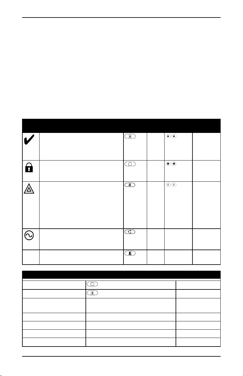
Ready - I ndicates system normal. Must
be on to arm system. All zones must be
secured or bypassed and the system disarmed for this light to activate.
Armed- Indicates system is armed . If
the Ready light and the Armed light are
both on, an Exit Delay is in progress.
Trouble - On indicates a system malfunction or tamper. Flashing indicates
that the keypad has a low battery condition. Follow the instructions displayed
or enter [*][2] to view trouble. Correcting the trouble turns off the indicator.
AC Power - Indicates AC Power is
present. T he AC Power light will turn
off when AC is absent.
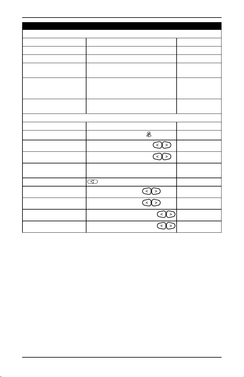
Actio n Press Section
Away Arm
Stay Arm
Night Arm When armed in stay mode [*][1] + [Access
Disarm [Access Code]
No-Entry Arming [*][9] + [ Access Code*]
Quick Arm /Quick Exit [*][0]
Abort Arming Sequence [Access Code]
for 2 seconds + [Access Code*]
for 2 seconds + [Access Code*]
Code*]
Function
Keys
Statu s
Emergency
Lights
Keys
Stay
Arm
Away
Arm
Chime Panic Alarm
Reset
Sensors
Quick
Exit
Emergency
Keys
Fire Alar m
Medical
Alarm
3.1.2
3.2
3.3
3.1
3.4
3.5
- 3 -
Page 5
Chapter 1.0 Quick Refer ence
Actio n Press Section
Bypassing - All bypass co mmands begin with [*][1] + [Access Code*]
Bypass Individual Zones [3 Digit Z one #]
Bypass All Open Zones [9][9][ 8]
Recall Last Bypass [9][9][9]
Clear Bypass [0][0][0] OR [Scroll] Bypass Options + [*]
+ [Scroll] Clear Bypasses + [*]
Program Bypass Group [3 digit zone #s] + [9][9][5] OR [3 digit
zone #s] + [ Scroll] Bypass Options + [*] +
[Scroll] Prg Bypass Group + [*]
Load Bypass Group [9][9][1] OR [Scroll] Bypass Options + [*]
+ [Scroll] Bypass Group + [*]
Common F unctions
Set Time and Date [*][6] [Master Code] + [0][1]
Turn Chime ON/OFF
Change Brightness
Change Contrast
Add/Delete User [*][5] + [ Master Code] + [ Access Code] +
Reset Smoke Detectors OR [ *][7][2]
View Tr oubles
View Alarms
Perform System Test
Buzzer Volume
[*][4] + [ Access Code*] OR
[*][6] [Master Code] + [1][2] +
[*][6] [Master Code] + [1][3] +
1
[*][2] + [ Access Code*] +
[*][3] + [ Access Code*] +
[*][6] + [ Master Code] + [ 0][4] +
[*][6] + [ Master Code] + [ 1][4] +
3.7.1
3.7.1
3.7.1
3.7.1
3.8
3.8
8.2
10.1
8.8
8.8
7.0
5.2
8.15
5.1.5
4.4
8.10
- 4 -
Page 6
Chapter 2.0 Understanding Your Keypad
5
9
6
12
7
10
11
1
8
15
2
3
4
17
16
14
13
5
9
7
6
2.0 Understanding Your Keypad
The PowerSeries Neo Alarm System supports a variety of wireless, hardwired and proximity
sensor LCD, LED and Icon keypads. All keypads come equipped with the L ED status lights
described in section 1 "Quick Reference". HS2LCD series keypads display system messages on
their L CD screen. HS2ICN series keypads display messages, as described in the following section.
HS2LED ser ies keypads display messages via a series of numbered LEDs, as described in the following section. All keypad versions will have a solid blue LED bar that is always on steady except
when, if enrolled, a proximity tag is presented to and successfully read by the keypad.
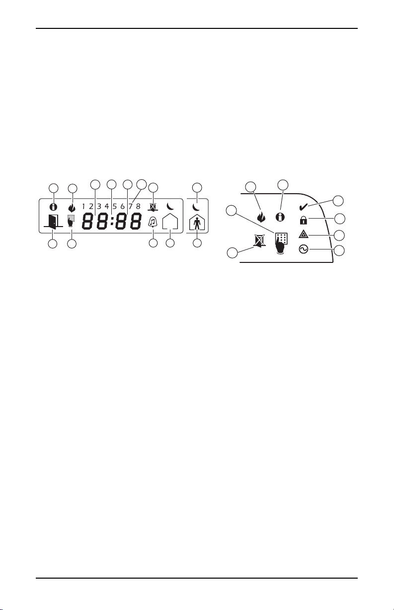
2.1 Icon and LED Keypad Symbols
HS2ICNSeries HS2LEDSeries
1. Clock Digits 1, 2 These two 7 segment clock digits indicate the hour digits when the
local clock is active. Digit 2 is also used to identify the zone number as the 1 when the zone number is 100 or higher and the OPEN
or ALARM icons are active.
2. : (Colon) This icon is the hours/minutes divider and will flash once per
second when the local clock is active.
3. Clock Digits 3, 4 These two 7 segment displays are the minute digits when the local
clock is active. T he digits 3 and 4 are used to indicate the zone
number for open zones or alarm in memory. These two digits combined with the clock digit 2, scr oll one zone per second from the
lowest number to the highest, when scr olling through zones.
4. 1 to 8 These numbers identify troubles when [*][2] is pressed.
5. Memory Indicates that there are alarms in memory.
6. Bypass Indicates that there are zones bypassed.
7. Program Indicates that the system is in Installer or User's programming, or
that the keypad is busy, and the LED will flash in cadence of
250ms ON and 250ms OFF. If Access Code is required, while
accessing star menus, this LE D is ON and solid to indicate that the
code is required.
8. Away Indicates that the panel is armed in the Away Mode.
9. Fire Indicates that there are f ire and/or CO alarms in memory.
10. Stay Indicates that the panel is armed in the Stay Mode.
- 5 -
Page 7

Chapter 2.0 Understanding Your Keypad
11. Chime This icon turns on when the Chime function key is pressed to
enable Door Chime on the system. It will turn off when the chime
function key is pressed again to disable Door Chime.
12. OPEN This icon is used with clock digits 1 and 2 to indicate activated
zones (not alar m) on the system. When zones are opened, the
OPEN icon will turn on, and 7 segment displays 1 and 2 will scroll
through the violated zones.
13. AC Indicates that AC is present at the main panel.
14. System Trouble Indicates that a system trouble is active.
15. Night Indicates that the panel is armedin the Night Mode.
16. Ready Light (green) If the Ready light is on, the system is ready for arming. If the
toggle of the Ready LED flashes for Force Arming enabled, the
LED flashes with force ar mable zones open on the partition.
17. Armed Light (red) If the Armed light is on, the system has been armed successfully.
Note:For UL listed installations, zones can only be bypassed manually.
2.2 Keypad Models
Note:In the following list if x = 9 ( the system operates in 912-919MHz) , x=4 (the system operates
in 433MHz band) or x=8 (the system operates in 868MHz band). Only models operating in 912919MHz band are UL/ULC listed.
HS2LCD Alphanumeric LCD keypad
HS2LCDP Alphanumeric LCD keypad with Prox. Tag suppor t
HS2ICN Icon keypad
HS2ICNP Icon keypad with Prox. T ag support
HS2LED LED keypad
HS2LCDRFx Alphanumeric LCD keypad with wireless receiver
HS2LCDRFP x Alphanumeric LCD keypad with wireless receiver and Prox. tag support
HS2ICNRFx Icon keypad with wireless r eceiver
HS2ICNRFPx Icon keypad with wireless r eceiver and Prox. tag support
HS2LCDWFx Wireless Alphanumeric LCD keypad
HS2LCDWFP x Wireless Alphanumeric LCD keypad with Prox. Tag support
HS2LCDWFP Vx Wireless Alphanumeric LCD keypad with Prox. Tag support & Voice Promp
HS2TCHP Touchscreen keypad. For additional information, refer to the HS2TCHP
Touchscreen User Manual; part #: 29009478R001.
Note:For systems compliant with E N50131-1 and EN50131-3 the HS2LE D keypad shall be used in
conjunction with an LCD type keypad (HS2LCD(P) or HS2LCDRF(P)8 or HS2LCDWF(P)8 in
order to be able to r eview logged events and also to allow overriding of conditions that inhibit setting of the alarm system. The HS2LED keypad alone `cannot support these functions.
- 6 -
Page 8

Chapter 3.0 The PowerSeries Neo Security System
3.0 The PowerSeries Neo Security System
Your PowerSeries Neo has been designed to provide you with the greatest possible flexibility and
convenience. Read this manual carefully and have your installer instruct you on how to operate your
system and which features have been implemented in your system. All users of this system should
be equally instructed in its use. Fill out section "System Information" with all of your zone information and access codes and store this manual in a safe place for future reference.
Note:The PowerSeries Neo security system includes specific false alarm reduction features and is
classified in accordance with ANSI/ SI A CP-01-2010 Control Panel Standard - Features for False
Alarm Reduction. Please consult your installer for further information regarding the false alarm
reduction features built into your system as all are not covered in this manual.
3.1 General System Operation
Your security system is made up of a PowerSeries Neo control panel, one or more keypads and various sensors and detectors. The control panel will be mounted out of the way in a utility closet or in
a basement. The metal cabinet contains the system electronics, fuses and standby battery.
All the keypads have an audible indicator and command entry keys. LED keypads have a group of
zone and system status lights. LCD keypads have an alphanumeric liquid crystal display (LCD).
The keypad is used to send commands to the system and to display the current system status. The
keypad(s) will be mounted in a convenient location inside the protected premises close to the
entry/exit door(s). The security system has several zones of ar ea protection and each of these zones
is connected to one or more sensors (motion detectors, glassbreak detectors, door contacts, etc.). A
sensor in alarm is indicated by the corresponding zone lights flashing on an LED keypad or by messages on the LCD keypad.
Note:Only the installer or service professional shall have access to the control panel.
3.2 Testing Your System
Tests all system keypad LEDs, keypad sounders, bells and/or sirens.
To ensure that your system continues to function as intended, you must test your system weekly.
IMPORTANT:For UL HOME HEALTH CARE listed applications the system shall also be
tested weekly without AC power. To remove AC from the control unit, remove the screw from the
restraining tab of the plug in adapter and remove the adapter from AC outlet. After completing the
test of the unit using only the battery backup source, reconnect the plug in adapter and attach the
screw through the restraining tab so that the adapter is securely attached to the outlet.
IMPORTANT:Should your system fail to function properly. contact your installation company.
IMPORTANT:All smoke detectors must be tested by your smoke detector installer once per year.
To Perform a Keyp ad and Siren Test LCD Display
1. From the Ready state press [*][6] and enter the [Master Code]
to access User Functions.
2. Press [ 04] or use the scroll keys to navigate to System Test and
press [*]. The system activates all keypad sounders, bells/sirens
and keypad LEDs for two seconds.
3. To go back to the Ready state press [#].
- 7 -
Press (*) for <>
User Functions
Press (*) for <>
System Test
Page 9

Chapter 3.0 The PowerSeries Neo Security System
3.3 Monitoring
This system is capable of transmitting alarms, troubles and emergency information. If you initiate
an alar m by mistake, immediately call the central station to prevent an unnecessary response.
Note:For CP-01 systems, the monitoring function must be enabled by the installer before it
becomes functional. There is a communicator delay of 30 seconds in this control panel. It can be
removed, or it can be increased up to 45 seconds, at the option of the end-user by consulting with
the installer.
3.4 Maintenance
With normal use, the system requires minimum maintenance. Note the following points:
l Do not wash the security equipment with a wet cloth. L ight dusting with a slightly
moistened cloth should remove normal accumulations of dust.
l Use the system test described in “Testing Your System” to check the battery condition.
We recommend, however, that the standby batteries be replaced every 3-5 years.
l For other system devices such as smoke detectors, passive infrared, ultrasonic or
microwave motion detectors or glassbreak detectors, consult the manufacturer’s literature
for testing and maintenance instructions.
- 8 -
Page 10

Chapter 4.0 Ar ming the System
4.0 Arming the System
The PowerSeries Neo system can be armed using a keypad, a 2-way wireless key or a proximity
tag.
4.1 Arming the System (Infinite Exit Delay)
In an attempt to reduce false alarms, your system is designed to notify you of an improper exit when
arming the system. When using the Push to Set, or Final Door Set feature, attempting to arm your
system will start an infinite exit delay. The keypad will sound a beep once per second. When you
have opened and closed the final exit door, or after pressing the Push to Set button, the exit delay
will be reduced to a programmable value, which is typically 10 seconds, after which the alarm will
complete the setting. T he panel used this time period to allow time for the detectors on the system
to return to their normal state. When this time expires, the system checks for detectors/windows/doors that may be open. If any of these are open, the panel will cancel the arming. If
this occurs, you must re-enter the premises, check the system, close any open zones, and then
attempt to arm again.
4.2 Away Arming the System with the Keypad
Away mode activates the complete alarm system by:
l Arming all perimeter sensors.
l Arming all interior sensors.
ToArmtheSysteminAwayMode LCDDisplay
1. Ensure all windows and doors are closed and that the Ready
indicator is on.
2. To arm using the Away key , press and hold the Away
key for 2 seconds and, if required, enter your [access code] or
present your proximity tag.
OR
To Quick Arm the system press [*][0].
3. If zones have been bypassed, ICN or L ED keypads bypass
LED will light and the bypassed zones #s will be shown.
On an LCD keypad a warning appears.
4. After successfully initiating the arming sequence the:
Armed indicator turns on.
l
Ready indicator remains lit.
l
l Exit Delay timer begins counting down.
l Keypad beeps six times, continues beeping once per second
until beeping rapidly in the final ten seconds.
l The system may be configured to have a persistent exit
delay that only ends when the exit door is opened and
closed, or when a button is pressed outside the protected
premises.
Date Time
JAN 02/13 2:06a
System is
Ready to Arm
then
Present Tag or
Enter Code
* Warning *
Bypass Active
Exit Delay in
Progress
- 9 -
Page 11
Chapter 4.0 Ar ming the System
6
7
1
2
3
4
5
5
2
3
4
1
6
5. To cancel the arming sequence, enter your [ access code] or
present your proximity tag to the keypad reader.
6. Once the exit delay timer expires, thereby arming the system,
the:
System Disarmed
No Alarm Memory
System Armed
in Away Mode
l Ready indicator turns off.
l Armed indicator r emains on.
l Keypad stops sounding.
Note:The installer configures the exit delay timer and whether or not an access code is required
for arming the system.
4.3 Exit Delay Time Restart
The control panel provides an option where, if a entry/exit zone is tripped a second time prior to the
end of the exit delay, the exit delay time restarts. The exit delay timer can only be restarted once.
4.4 Alarm Cancel Window
The control panel provides a period of time in which the user can cancel the alarm transmission. If
the programmed alarm transmission delay has expired, canceling an alarm sends a message to the
monitoring station. Upon a successful transmission of the cancellation message the keypad will beep
6 times.
Note:Must be enabled and configured by installer.
Note:For CP-01 systems, alarm transmission delay must not exceed 45 seconds.
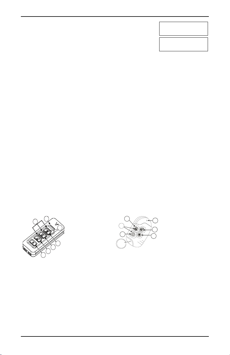
4.5 Using 2-way Wireless Keys and Proximity Tags
2-way wireless keys allow users in the close proximity of their house the ability to readily arm/disarm their system, and to call for help. For information on enrolling wireless keys see "User Labels
(LCD keypads only)".
1. Away Arm
2. Stay Arm
3. Disarm
4. Panic
5. Command Output 1
6. Message LED
1. Away Arm
2. Stay Arm
3. Disarm
4. Panic
5. Command Output 1
6. LED
7. Status LE Ds
Note:Panic feature has not been evaluated by UL . All wireless key buttons are programmable.
Verify the functions assigned to each key with your installer. When using compatible wireless keys
there is one bell squawk for arming and two bell squawks for disarming.
- 10 -
Page 12

Chapter 4.0 Ar ming the System
4.5.1 Arming the System with a 2-Way Wireless Key
If configured, the PowerSeries Neo system can be armed using the following wireless keys:
l PG4929/PG8929/PG9929
l PG4939/PG8939/PG9939
To Arm the System with a 2-way wireless key
l Press the desired Arming mode button anytime the system Ready indicator is on.
4.5.2 Arming the System with a Proximity Tag
Depending on how your keypad is programmed, proximity tags can be used to either arm/disarm the
system or to perform a programmed function (e.g. unlock a cabinet or storeroom door).
To Arm the System with a Proximity tag
l Present your Proximity tag to a keypad equipped with a proximity sensor anytime the sys-
tem Ready indicator is on.
l If configured by your installer , enter your access code.
4.6 Disarming the System
Depending on your system configuration, there are multiple methods you can use to disarm your system. You can disarm the system using a:
l 2-way wireless key
l Proximity tag
To Disarm the System with a Keypad
1. Enter your [access code] or present your proximity tag anytime the system is armed .
(Armed indicator is on).
2. If you walk through the entry door, the keypad will beep. Disarm within _____ seconds to
avoid an alarm condition.
To Disarm the System with a 2-way Wireless Key
1. Press the disarm button anytime the system is armed. (Ar med indicator is on).
2. If you walk through the entry door the keypad will beep. Press the disarm button within ____
seconds to avoid an alarm condition.
Note:Af ter disarming a system with an HS2LCD keypad using a 2-way wireless key, always
check the alarm memory to determine if any alarms have occurred during the armed period.
To Disarm the System with a Proximity Tag
1. Present your proximity tag to a keypad equipped with a proximity sensor anytime the system
is armed . (Armed indicator is on) and if configured as required, enter your access code.
2. If you walk through the entry door the keypad will beep. Present your proximity tag within
_____ seconds to avoid an alarm condition.
Note:Duration of Entry timer is programmed by installer. The installer will advise the maximum
duration of entry delay that was programmed in the system. It cannot exceed 45 seconds.
4.6.1 Disarming Error
If your code is invalid, the system will not disarm and a 2-second error tone will sound. If this
occurs, press [#] and re-enter your access code.
- 11 -
Page 13

Chapter 5.0 Emergency Keys
5.0 Emergency Keys
IMPORTANT:EMERGENCY USE ONLY!
Pressing both the emergency keys generates a Fire, Medical, or Panic Alarm, and alerts the monitoring station. e.g., to generate a medical alarm press both of the medical alarm keys for 2 seconds
and the display on an LCD keypad will show Hold down keys for Med. Alarm.The keypad beeps to
indicate that the alarm input has been accepted and sent to the monitoring station.
Fire Alarm
Medical Alarm
Panic Alarm
Note:Verify with your alarm company that your system is equipped with emer gency keys.
Note:Fire keys can be disabled by the installer.
Note:Having an optional audio verification module installed in your system allows the monitoring
station to open 2-way communication when notified of an alarm.
- 12 -
Page 14

Chapter 6.0 Access Code Types
6.0 Access Code Types
The alarm system provides the following user access code types:
Cod e Ad d User Delete
User
Master All All Yes Yes Yes Yes No
User No No Yes Yes No No No
Supervisor All but
Master
Duress No No Yes Yes No No No
One-time
user
Installer and Master code are system codes that can be changed but not deleted. The other codes are
user-defined and can be added or deleted as necessary. By default, access codes have the same partition and attribute programming as the code used to program them.
Note:When using 8-digit access codes, the minimum number of variations are:
l 2083333 for HS2016/HS2016-4
l 1388888 for HS2032
l 1052631 for HS2064/HS2128
l 200000 f or HS2064 E
l 100000 f or HS2128 E
Additionally, there are no disallowed codes.
Master
Cod e
User
Cod es
Supervisor
Cod es
Duress
Cod es
One Time
User Code
No No Yes 1/day No No No
By default the master code can access all partitions and can perf orm any keypad
function. This code can be used to program all access codes, including the supervisor and duress codes. The master code is code # [01].
This type of access code is used to arm and disarm assigned partitions and can
access the User Functions menu.
Use when you want to allow additional users to manage Access Codes [*5] or User
Functions [*6]. Supervisor codes created by the master code will have the same
attributes as the master code. Supervisor codes created by another supervisor code
will have the same attributes, except the supervisor attribute. Must be assigned
manually afterwar d. After creation, attributes can be changed for all supervisor
codes. For information on how to program a supervisor code see "Configuring additional User Options".
Use if forced to access your keypad under threat. Duress codes function the same
as user access codes, except they transmit a Duress Report to your monitoring station when used to perform any function on the system.
Duress codes cannot be used to access Access Codes [*5], User Functions [*6] or
Installer [*8] menus. For information on how to program a Duress Code see "Configuring additional User Options".
Used to grant someone one-time access to your home once per day, i.e., a cleaning
person or contractor. The ability to disarm the system is reset at midnight or when
the one-time user code is keyed in by the master code user. For information on how
to program a One Time User Code see "Configuring Additional User Options".
All but
Master
Arm Disarm Access
Cod es
Yes Yes Yes Yes No
User Fu nctions
Installer
- 13 -
Page 15

Chapter 6.0 Access Code Types
To Open the Access Codes Menu LCD Display
1. Press [ *][5]
OR
press [*] and use the scroll keys to navigate to Access Codes
and press [*].
2. Enter [Master or supervisor code].
3. Enter [User #]
OR
scroll through the list of users and press [*]. On an LED
keypad the user number will begin flashing.
4. To go back to the Ready state press [#].
Press (*) for <>
Access Codes
Present Tag or
Enter Code
Press (*) for <>
{User Label}
6.1 Adding, Changing and Deleting Access Codes
Each configured user is assigned a number as follows:
l 01-48 for HS2016/HS2016-4
l 01-72 for HS2032
l 01-95 for HS2064/HS2128
l 001-500 for HS2064 E
l 0001-1000 for HS2128 E
Access codes cannot be duplicated.
To Add or Change User Access Codes LCD Display
1. From the desired user press [*] or [1].
2. Enter a new 4, 6, or 8-digit access code. After entering a new
code you will be automatically returned to the previous menu,
and on an LCD display the flag is changed to P from -. On an
ICN or LED keypad the programmed user will have their
digits displayed. If a duplicate code is entered the error tone
will sound. After the code is programmed, the keypad returns
to the previous LCD display.
To Delete a User Access Co de LCD Display
1. From the desired user press [*] or [1].
2. Press [ *]. The code is deleted, and you are returned to the previous screen. The flag is changed to - fr om P. On an ICN or
LED keypad the programmed user’s digits will cease being displayed. After the code is programmed, the keypad returns to
the previous LCD display.
Note:Any proximity tags associated with deleted user codes will need to be re-enrolled.
Press (*) for <>
Access Code
Enter New Code
AAAA
Press (*) for <>
Access Code
Enter New Code
030516
- 14 -
Page 16

Chapter 6.0 Access Code Types
6.2 Burglary Verification
The Control Panel includes cross zone and sequential detection features that require a trip on two or
more zones within a given time period, to generate a confirmed alarm and immediate police
response.
Note:Must be enabled and configured by installer.
6.3 Swinger Shutdown
The Control Panel has a swinger shutdown feature that when enabled a programmable number of
trips shall shut down the zone. All burglary zone types have this feature enabled in CP-01 installations.
Note:Must be enabled and configured by installer.
6.4 Call Waiting
The Control Panel includes a programmable option for call waiting to prevent a call waiting line
from interfering with the alarm verification process. This option is disabled by default.
Note:Must be enabled and configured by installer.
6.5 Fire Alarm Verification
Fire Alar m Verification is an available option for Fire zones. I f configured, once the conditions for
alarm verification are met the fire alarm will sound and an alarm transmission will be sent to the
monitoring station.
Note:Must be enabled and configured by installer.
6.6 System Lockout due to Invalid Attempts
If too many invalid access codes are entered, your system can be configured to automatically lock
out inputs from all keypads, wireless and proximity keys, and SMS commands for a specified duration. When any keys are pressed, an error tone will sound. FMP keys are still active during
Keypad Lockout.
Note:Feature and lockout duration must be configured by installer.
6.7 User Labels (LCD keypads only)
Adding or editing labels is done by using a pre-programmed word library. T he following table library lists the full librar y and the associated three digit code.
To Edit a User Label LCD Display
1. From the applicable user, press [3] or use the scroll keys to
scroll to User Labels and press [*].
2. Press [ *] [ *] to enter word library.
3. Use the scroll keys to scroll through the list of words or use the
[3-digit number] to display the desired word. Press [*] to
select the word.
4. To enter an additional word, repeat step 3.
- 15 -
Press (*) for <>
User Labels
Program Name
{User 1 Label 1}
Press (*) for
{User Label}
Page 17

Chapter 6.0 Access Code Types
Word Libr ary
# Text # Text # Text # Text # Text # Text
001 Abo rted 0 41 Communicator 081 Front 121 Memory 161 Screen 201 7
002 AC 042 Compu ter 082 Furnace 122 Menu 162 Second 202 8
003 Access 043 Control 083 Gallery 123 Monoxi de 163 Sensor 203 9
004 Acti ve 0 44 Date 084 Garage 124 Mother’s 164 Service 204 A
005 Acti vity 045 Daughter’s 085 Gas 125 Motion 165 Shed 2 05 B
006 Alarm 046 Degrees 0 86 Gl ass 126 No 166 Shock 2 06 C
007 All 047 Delay 087 Good bye 127 North 167 Shop 207 D
008 AM 048 Den 08 8 Gym 128 Not 168 Side 208 E
009 Area 049 Desk 089 Hallway 129 Now 169 Siren 209 F
010 Arm 050 Detecto r 090 Heat 130 Number 17 0 Slid ing 210 G
011 Armed 051 Di ning 091 Hello 131 Off 17 1 Smoke 211 H
012 Arming 05 2 Disarmed 0 92 Help 132 Office 172 Son’s 212 I
013 Attic 053 Door 093 High 133 OK 173 Soun d 213 J
014 Aux il iary 054 Down 094 Ho me 13 4 On 174 South 214 K
015 Away 055 Do wnl oad 09 5 House 135 Open 175 Special 215 L
016 Baby 056 D own stairs 0 96 In 136 Opening 17 6 Stairs 216 M
017 Back 057 Drawer 097 Ins tall 137 Panic 177 Stay 21 7 N
018 Bar 058 Driveway 098 Int erior 138 Partition 17 8 Sun 218 O
019 Basement 0 59 Du ct 099 Int rusi on 139 Pati o 179 Supervi sory 219 P
020 Bathroom 06 0 Duress 100 Invalid 140 Pet 180 Sys tem 220 Q
021 Battery 06 1 East 101 Is 141 Phone 181 Tamper 221 R
022 Bedroom 062 Energy 102 Key 142 Please 182 Temperature 22 2 S
023 Bonus 063 E nter 103 Kids 1 43 PM 183 Test 223 T
024 Bott om 06 4 Entry 104 Ki tchen 144 Police 184 Ti me 224 U
025 Breezeway 065 Error 105 Latchk ey 145 Pool 185 To 225 V
026 Buil ding 066 E xercise 106 L aund ry 146 Porch 186 Tou chpad 226 W
027 Bus 067 Ex it 1 07 Left 147 Power 187 Trouble 227 X
028 Bypass 068 Exterior 10 8 Level 148 Press 18 8 Unb ypass 228 Y
029 Bypassed 069 Factory 109 Li brary 149 Program 189 Unit 229 Z
030 Cabinet 070 Failu re 110 Light 150 Progress 190 Up 230 (Space)
031 Camera 071 Family 111 Li ght s 1 51 Qu iet 191 West 23 1 ‘
032 Canceled 072 Father’s 112 Livi ng 152 Rear 1 92 Wi ndow 232 - (Dash)
033 Car 073 Feature 113 Load 153 Receiver 193 Zone 23 3 _
034 Carbon 074 Fence 114 Loadi ng 154 Report 194 0 234 *
035 Central 07 5 Fire 115 Low 155 RF 195 1 235 #
036 Chime 076 First 1 16 Lower 156 Righ t 196 2 236 :
037 Clos ed 077 Flo or 11 7 Main 157 Room 197 3 237 /
038 Clos et 078 Force 118 Master 158 Safe 198 4 2 38 ?
039 Clos ing 079 Foyer 119 Mat 159 Saver 199 5 239
040 Code 080 Freeze 120 Medical 160 Schedul e 20 0 6 240
- 16 -
Page 18

Chapter 7.0 Trouble Conditions
7.0 Trouble Conditions
Occasionally, you may have a problem with your Alar m Controller or telephone line. If this happens, your Alarm Controller identifies the problem and displays an err or message. Refer to the
provided list when you see an error message on the display. If additional help is required, contact
your distributor for service.
Note:This equipment contains no user-serviceable parts, except for the keypad batteries. Dispose
of used batteries as per local rules and regulations.
When the system detects a trouble condition the following occurs:
l The Trouble indicator turns on.
l The keypad beeps once every 10 seconds.
l Press the [*] key to silence the keypad beeps.
Press [ *][2] to examine troubles. When viewing troubles, the trouble indicator flashes to identify
the level of trouble being viewed. One f lash = level 1, two flashes = level 2 etc.
Arming of your system may be impeded by a trouble. To override this condition, enter [*2], scr oll
to Acknowledge All T roubles and press [*] or enter 999.
Trou ble
Con dition
Note:Trouble #s are used to identify the number to view the trouble and depending on the keypad
type being used, identifies which LED or digit illuminates to display the trouble. Similarly,
Trouble Notification identifies the range that may be displayed on the keypad. When exploring the
trouble levels, the Tr ouble indicator will flash to identify which level you are currently viewing.
Service
Required
Trou ble
#
Level 1
01 Assorted Trouble types.
Description
Time and Date troubles can
be resolved by resetting the
Time/Date. To set Time/Date
press [*][6][ 0][1]. For all
other troubles call for service.
Trou ble
Types
Bell Circuit 01
RF Jam 02
Auxiliary
Supply
Loss of clock 04
Output 1
Fault
Trou ble
#
Level 2
03
05
Trou ble
Notification
Level 3
- 17 -
Page 19

Chapter 7.0 Trouble Conditions
Trou ble
Con dition
Trou ble
#
Level 1
Description
Battery Trouble 02 The system has detected a bat-
tery tr ouble condition. Call
for service.
Bus Voltage 03 A module has detected a low
voltage on its corbus red ter minal.
AC Troubles 04 The system is experiencing
loss of power. Call f or service.
If the building and/or neighborhood has lost electrical
power, the system will continue to operate on battery for
several hours.
Trou ble
Types
Low Battery
Trou ble
#
Level 2
01 n/a
Trou ble
Notification
Level 3
(System
Label)
No Batter y
service (Sys-
02
n/a
tem Label)
High Current
04 Module 1-4
Output Low
Battery
High Current
05 Module 1-4
Output No
Battery
Power Supply
07 Module 1-4
Low Battery
Power Supply
No Batter y
08 Power supply
1-4
HSM2HOST 01 n/a
Keypad 02 Keypad 1-16
Zone
Expander
04 Zone
expander 115
Power Supply 05 Power supply
1-4
High Current
Output
Output
Expander
HSM2955
Bus Voltage
06 Output ter-
minal 1-4
08 Output mod-
ule 1-16
09
n/a
(Audio
Expander)
Zone 01 Zone label or
001-128
Siren 03 Sir en 1-16
Repeater 04 Repeater 1-8
Power Supply 05 Power supply
1-4
High Current
Output
06 Output ter-
minal 1-4
System Label 07 n/a
- 18 -
Page 20

Chapter 7.0 Trouble Conditions
Trou ble
Con dition
Trou ble
#
Level 1
Description
Device Faults 05 The system has detected an
issue with one or more connected devices. Call for service.
Device Battery 06 The system has detected an
issue with one or more of the
device batter ies. For Z one,
Keypad and Wireless Key battery tr oubles see the accompanying documentation for
how to change the batteries.
Device
Tampers
07 The system has detected a
tamper condition with one or
more devices on the system.
Call for service.
RF Delinquency 08 T he system has detected wir e-
less signal interference that is
causing improper system operation. Call for service.
Trou ble
Types
Gas
Heat
CO
Freeze
Probe Dis-
Trou ble
#
Level 2
Trou ble
Notification
Level 3
connected
Fire
Zone 01 Zone label or
001-128
Keypad 02 Keypad 1-16
Siren 03 Sir en 1-16
Repeater 04 Repeater 1-8
Zone 01 Zone label or
001-128
Keypad 02 Keypad 1-16
Siren 03 Sir en 1-16
Repeater 04 Repeater 1-8
User 05 Wireless key
1-32
Zone 01 Zone label or
001-128
Keypad 02 Keypad 1-16
Siren 03 Sir en 1-16
Repeater 04 Repeater 1-8
Audio Station 05 Audio Station
1-4
Zones 01 Zone label or
001-128
Keypad 02 Keypad 1-16
Siren 03 Sir en 1-16
Repeater 04 Repeater 1-8
- 19 -
Page 21

Chapter 7.0 Trouble Conditions
Trou ble
Con dition
Module Supervision
Trou ble
#
Description
Level 1
09 The system has detected a
supervisory trouble condition
with one or more modules on
the system. Call for service.
Module
Tampers
10 The system has detected a
tamper condition with one or
more modules on the system.
Call for service.
Communications 11 The system has detected a
communication trouble. Call
for service.
Trou ble
Types
Trou ble
#
Level 2
Trou ble
Notification
Level 3
HSM2HOST 01 n/a
Keypad 02 Keypad 1-16
Zone
Expander
04 Zone
Expander 115
Power Supply 05 Power supply
1-4
High Current
Output
Output
Expander
Audio
Expander
06 Output ter-
minal 1-4
08 Output mod-
ule 1-16
09
n/a
HSM2HOST 01 n/a
Keypad 02 Keypad 1-16
Zone
Expander
04 Zone
Expander 115
Power Supply 05 Power supply
1-4
High Current
Output
Output
Expander
Audio
Expander
06 Output ter-
minal 1-4
08 Output mod-
ule 1-16
09
n/a
Alt. Comm 10 n/a
TLM Trouble 01 n/a
FTC T rouble 02 Receiver 1-4
SIM Lock 03 n/a
Cellular 04 n/a
Ethernet 05 n/a
Receiver 06 Receiver 1-4
Supervision
07 Receiver 1-4
Receiver
Alt Comm
Fault
Alt Comm
09
n/a
10 Receiver 1-4
FTC
- 20 -
Page 22

Chapter 7.0 Trouble Conditions
Trou ble
Con dition
Not Networked 12 The system has detected a net-
Trou ble
#
Level 1
Description
work trouble condition with
one or more modules on the
system. If the trouble does not
restore within 20 minutes,
call for service.
Trou ble
Types
Zone 01 Zone label
Keypad 02 Keypad 1-16
Siren 03 Sir en 1-16
Repeater 04 Repeater 1-8
User 05 User s 01-
Trou ble
#
Level 2
Trou ble
Notification
Level 3
001-128
1000
- 21 -
Page 23

Chapter 8.0 Safety Instructions
8.0 Safety Instructions
This equipment is stationary-fixed DIRECT PLUG-IN and must be installed by Ser vice Persons
only (Service Person is defined as a person having the appropriate technical tr aining and experience
necessary to be aware of hazards to which that person may be exposed in performing a task and of
measures to minimize the risks to that person or other persons). It must be installed and used within
an environment that provides the pollution degree max 2, over voltages category II, in non-hazardous, indoor locations only.
WARNING!This equipment has no mains on/off switch; if the equipment must be quickly disconnected, the plug of the direct plug-in power supply is intended to serve as the disconnecting
device; it is imperative that access to the mains plug and associated mains socket/outlet, is never
obstructed.
When using equipment connected to the mains and/or to the telecommunication network, there are
basic safety instructions that shall always be followed. Refer to the saf ety instructions provided
with this product and save them for future reference. To reduce the risk of fire, electric shock
and/or injury, observe the following:
l Do not attempt to service this product yourself. Opening or removing the cover may
expose you to dangerous voltage or other risk. Refer servicing to service persons. Never
open the device yourself.
Use authorized accessories only with this equipment!
l
DO NOT leave and/or deposit ANY object on the top of the cabinet of this equipment!
The cabinet as it is installed on the wall, is not designed to support any supplementary
weight!
l Do not touch the equipment and its connected cables during an electrical storm; there may
be a r isk of electric shock.
Never touch un-insulated wires or terminals unless the equipment has been disconnected
l
from the mains supply and from the telecommunication network!
l Ensure that cables ar e positioned so that accidents cannot occur. Connected cables must
not be subject to excessive mechanical strain. Do not spill any type of liquid on the equip-
ment.
l Do not use the Alarm system to report a gas leak if the system is near a leak.
These safety instructions should not prevent you from contacting the distributor and/or the manufacturer to obtain any further clarification and/or answers to your concerns.
8.1 Regular Maintenance and Troubleshooting
Keep your Alarm Controller in optimal condition by following all the instructions that are included
within this manual and/or marked on the product. It is the end-user and/or installer’s responsibility
to ensure that the disposal of the used batteries is made according to the waste recovery and recycling regulations applicable to the intended market.
8.1.1 Cleaning and Maintenance
l Clean the units by wiping with a damp cloth only.
l Do not wipe the front cover with alcohol.
l Do not use any water or any other liquid.
- 22 -
Page 24

Chapter 8.0 Safety Instructions
l Do not use abrasives, thinners, solvents or aerosol cleaners (spray polish) that may enter
through holes in the Alarm Controller and cause damage.
Use the system test described in “Testing Your System” to check the battery condition.
l
We recommend, however, that the standby batteries be replaced every 3-5 years.
For other system devices such as smoke detectors, passive infrared, ultrasonic or
l
microwave motion detectors or glassbreak detectors, consult the manufacturer’s literature
for testing and maintenance instructions.
This publication covers the following models: x = 9 (912-919MHz UL/ULC systems) 4 (433MHz)
or 8 (868MHz).
l H S2016 l HS2128 l H S2LCDRF l HS2LED
l H S2016-4 l HS2128 E
l H S2032 l HS2TCHP
l H S2064 l HS2LCD
l H S2064 E l HS2LCDP
l HS2LCDRFPx
l
HS2LCDWFx
l
HS2LCDWFPx
l
HS2LCDWFPVx
l H S2ICN
l H S2ICNP
l
HS2ICNRFx
l
HS2ICNRFPx
- 23 -
Page 25

Chapter 9.0 EULA
9.0 EULA
IMPORTANT - READ CAREFULLY: DSC Softw are
purchased wit h or witho ut Prod ucts and Components
is copyrighted and i s pu rchased un der the fol lowin g
license terms:
This End-User Li cense Agreement (“EULA”) is a
legal agreement between You (the company , indi vidual or entity who acqui red the Software and any
related Hardware) and Digital Security Contro ls, a
division of Tyco Safety Products Canada Ltd .
(“DSC”), the manufacturer of the integrated security
systems and the developer of the soft ware and any
related products or compon ents (“HARDWARE”)
which You acqu ired.
If th e D SC so ftware prod uct (“SOFTWARE
PRODUCT” or “SOFTWARE”) is i ntended t o be
accompanied by HARDWARE, and is NOT accompanied by new HARDWARE, You may n ot use, copy
or ins tall the SOFTWARE PRODUCT. The
SOFTWARE PRODUCT i ncludes computer software,
and may include associated media, print ed materials ,
and “onl in e” or electroni c documentatio n.
Any software provid ed along wi th t he SOFTWARE
PRODUCT that is associated with a separate end-user
license agreement i s licensed t o You under t he terms
of that l icens e agreement.
By i nstall ing, copyi ng, do wnl oadi ng, st oring, accessing o r o therwise usin g the SOFTWARE PRODUCT,
You agree unconditi onally to be bound by the terms
of thi s EULA, even if this EULA i s deemed to be a
modifi catio n of any previous arrangement or contract.
If You do not agree to the terms of t his EULA, DSC
is unwill in g to l icens e t he SOFTWARE PRODUCT
to Yo u, and You have no right to use it .
SOFTWARE PRODUCT LICENSE
The SOFTWARE PRODUCT is protected by copyright laws and internation al copy right treaties, as
well as other in tellectual property laws and treaties.
The SOFTWARE PRODUCT is l icensed, not sold.
1. GRANT OF LICENSE This EULA grants You t he
followi ng right s:
(a) Software Install ation and Use - For each l icense
You acqu ire, You may have only one copy of t he
SOFTWARE PRODUCT i nstall ed.
(b) Storage/Network Use - The SOFTWARE
PRODUCT may n ot b e i nstall ed, accessed, displayed,
run, shared or us ed concurrently on or from different
computers, including a workstation, t erminal or ot her
digital electron ic devi ce (“Device”). In other words , if
You have s everal workstatio ns, You will have to
acquire a l icens e fo r each workst ation wh ere the
SOFTWARE wi ll be u sed.
(c) Backup Copy - You may make back-up copi es of
the SOFTWARE PRODUCT, b ut You may o nly have
one copy per l icens e i nstall ed at any given ti me. You
may use the back-up copy sol ely for archival purposes. Except as expressl y provid ed in t his EUL A,
You may not ot herwise make cop ies of the
SOFTWARE PRODUCT, in cluding the print ed materials accompanying th e SOFTWARE.
2. DESCRIPTION OF OTH ER RIGHTS AND
LIMITATIONS
(a) Limitation s on Reverse Engi neering, Decompil ation and Disassembly - You may n ot reverse
engineer, decompi le, or dis assembl e t he SOFTWARE
PRODUCT, except and only to the extent that su ch
activity is express ly permitted b y applicable law notwit hstanding thi s li mitation. You may n ot make any
changes or mod ifications to the Software, with out the
written permis sion of an officer of DSC. Yo u may
not remove any proprietary no ti ces, marks or labels
from the Software Product . Yo u shall insti tute reasonabl e measures to ensure compl iance wi th t he terms
and cond it ions of this EULA .
(b) Separati on o f Components - The SOFTWARE
PRODUCT is l icens ed as a s ingle product. Its component parts may n ot b e s eparated for use on more
than one HARDWA RE uni t.
(c) Sing le INTE GRATE D PRODUCT - If You
acquired t his SOFTWARE with HARDWA RE, then
the SOFTWARE PRODUCT is l icens ed with the
HARDWARE as a single integrated p rodu ct. In t hi s
case, the SOFTWARE PRODUCT may o nly be used
wit h the HARDWARE as set forth i n th is E ULA.
(d) Rent al - You may not rent, lease or lend the
SOFTWARE PRODUCT. You may n ot make it available to o thers o r p ost it o n a server or web site.
(e) Software Produ ct Transfer - You may transfer all
of Your rights under t hi s EULA only as part of a permanent sale or transfer of the HARDWARE, provided
You retai n no copies, Yo u trans fer all of the
SOFTWARE PRODUCT (inclu ding all component
parts, the media and printed materials, any upgrades
and this EULA), and provided t he recipient agrees to
the terms of th is E ULA. If the SOFTWA RE
PRODUCT is an u pgrade, any transfer must also
include all prior versions of the SOFTWARE
PRODUCT.
(f) Termination - Without preju dice to any ot her
rights, DSC may terminate this EULA if You fail to
comply with the terms and conditi ons of this EULA.
In such event, You mus t destroy al l copies of the
SOFTWARE PRODUCT and all of its compon ent
parts.
(g) T rademarks - This EULA does n ot grant You any
rights in con necti on with any trademarks or s ervice
marks o f D SC or its suppliers.
3. COPYRIGHT - All t itle and intellectual property
rights in and to the SOFTWARE PRODUCT (i nclu ding b ut n ot l imit ed to any images, photo graphs, and
- 24 -
Page 26

Chapter 9.0 EULA
text i ncorporated into the SOFTWARE PRODUCT),
the accompanying printed materials, and any copies
of the SOFTWARE PRODUCT, are own ed by DSC
or its sup pliers. You may no t copy the pri nted materials accompanying th e SOFTWARE PRODUCT. All
tit le and i ntellectual property right s in and to t he content which may be accessed through use of the
SOFTWARE PRODUCT are the pro perty o f t he
respective content ow ner and may be protected by
applicable cop yrig ht o r o ther intellectual prop erty
laws and treaties. This EULA grants You n o rights
to us e s uch content. All righ ts n ot expressl y granted
under this EULA are reserved by DSC and its sup pli ers.
4. EXPORT RESTRICTIONS - You agree that Yo u
wil l not expo rt or re-export the SOFTWA RE
PRODUCT to any country, person, o r entity subject
to Canadi an export restrictio ns.
5. CHOICE OF LA W - This Software License Agreement is governed b y th e l aws of the Provi nce of
Ontario, Canada.
6. ARBITRATION - All d isput es arising i n connection wi th t his Agreement shall be determined by
final and bin ding arbitration in accordance wi th t he
Arbitration Act, and the parties agree to b e b oun d by
the arbit rator’s d ecisi on. The place o f arbi tration
shall be Toro nto, Canada, and the language of the
arbitration shal l be Engli sh.
7. LIMITED WARRANTY
(a) NO WARRANTY - DSC PROVIDES TH E
SOFTWARE “AS IS” WITH OUT WARRANTY.
DSC DOES NOT WARRANT THAT THE
SOFTWARE WILL MEET YOUR REQUIREMENT S
OR THAT OPERATION OF THE SOFTWARE
WILL BE UNINTERRUPTED OR E RROR-FREE.
(b) CHANGES IN OPERATING ENVIRONMENT -
DSC shall n ot be resp onsib le for prob lems caused b y
changes i n th e operating characteris tics of the
HARDWARE, or for problems in the int eraction of
the SOFTWARE PRODUCT with non-DSCSOFTWARE or HARDWARE PRODUCTS.
(c) LIMITATION OF LIABILITY; WARRANT Y
REFLECTS ALLOCATION OF RISK - IN A NY
EVEN T, IF ANY STATUTE IMPLIES
WARRANTIES OR CONDITIONS NOT STATED
IN T HIS L ICENSE AGREEMENT, DSC’S ENTIRE
LIABILITY UNDER ANY PROVISION OF T HIS
LICENSE AGREEMENT SHALL BE LIMITED TO
THE GREATER OF THE AMOUNT ACTUALLY
PAID BY YOU TO LICENSE THE SOFTWARE
PRODUCT AND FIVE CANADIAN DOLLARS
(CAD$5.00 ). BECAUSE SOME JURISDICTIONS
DO NOT ALLO W THE E XCLUSION O R
LIMITATION O F LIABILITY FOR
CONSEQUENTIAL OR INCIDENTAL DAMAGES,
THE ABOVE LIMITATION MAY NOT APPLY TO
YOU.
(d) DISCLAIMER OF WARRANTIES - THIS
WARRANTY CONTAINS THE ENTIRE
WARRANTY AND SH ALL BE IN LIEU OF ANY
AND ALL OTHER WARRANTIES, WHETHER
EXPRESSED OR IMPLIED (INCLUDING ALL
IMPLIED WARRANTIES OF MERCHANT ABILITY
OR FITNESS FOR A PARTICULAR PURPOSE)
AND OF ALL OTHER OBLIGATIONS OR
LIABILITIES ON THE PART OF DSC. DSC
MAKES NO OTHER WARRANTIES. DSC
NEITHER ASSUMES NOR AUTHORIZES ANY
OTHE R PERSON PURPORTING TO ACT ON ITS
BEHALF TO MODIFY OR TO CHANGE THIS
WARRANTY , NO R TO ASSUME FOR IT ANY
OTHE R WARRANTY OR LIABILITY
CONCERNING THIS SOFTWARE PRODUCT.
(e) EXCLUSIVE REMEDY AND LIMITAT ION OF
WARRANTY - UNDER NO CIRCUMSTANCES
SHALL DSC BE LIABLE FOR ANY SPECIAL,
INCIDENTAL, CONSEQUENTIAL OR INDIRECT
DAMAGES BASED U PON BREACH OF
WARRANTY , BREACH OF CONTRACT,
NEGL IGENCE, STRICT LIABILITY, OR ANY
OTHE R LEGAL THEORY. SUCH DAMAGES
INCLUDE, BUT ARE NOT L IMITED TO, LOSS OF
PROFITS, LOSS OF THE SOFTWA RE PRODUCT
OR ANY ASSOCIATED EQUIPMENT, COST OF
CAPITAL, COST OF SUBSTITUTE OR
REPLACEMENT EQUIPMENT , FACILITIES OR
SERVICES, DOWN TIME, PURCHASERS TIME,
THE CLAIMS OF THIRD PARTIES, INCLUDING
CUSTOMERS, AND INJURY TO PROPERTY.
WARNING: DSC recommends t hat t he enti re s ystem
be completely tested on a regular basis. However, despit e frequ ent testing, and due to , but not limited to,
criminal t ampering o r electrical disrupt ion, i t is pos sib le for this SO FTWARE PRODUCT to fail to perform as expected.
Always ensureyou obtai nthe latestversionofthe
UserGuide.Updatedversions o fthis User Guide
area vai la blebyco ntacting yourdistributor.
- 25 -
Page 27

Chapter 10.0 Installer Warning
10.0 Installer Warning
Warning Please Read Carefull y
NoteToInstallers:
This warning contains vital information. As the only individual in contact with
system us ers, it is your responsibility to bring each item in this warning to the
attention of the users of this system.
System Failures
This s ys tem has been carefully designed to be as effective as possible. There
are circumstances, how ever, involving fire, burglary, or other types of emergencies where it may not provide protection. Any alarm system of any type may
be compromised deliberately or may fail to operate as expected for a variety of
reasons. S ome but not all of these reas ons may be:
InadequateInstall ation
A s ecurity system must be installed properly in order to provide adequate protection. Every installat ion should be evaluated by a security professional to
ensure that all access points and areas are cove red. Locks and latches on w indows and doors must be s ecure and operate as intended. Windows, doors,
walls , ceilings and other building materials must be of sufficient s trength and
construction to provide the level of protection expe cted. A reevaluation must be
done during and after any construction activity. An evaluation by the fire and/or
police department is highly recommended if this service is available.
Crimi nal Knowl edge
This s ys tem contains security features which were known to be effective at the
time of manufacture . It is possible for persons with criminal intent to develop
techniques w hi ch reduce the effectiveness of these features. It is important that
a security s ystem be reviewed periodically to ensure that it s features remain
effective and that it be updated or replaced if it is found that i t does not provide
the protection expec ted.
Access by Intruders
Intruders may enter through an unprotected acces s point, circumvent a sensing
device, evade detection by movi ng t hrough an area of insufficient coverage, disconnect a warni ng device, or interfere with or prevent the proper operation of the
system.
PowerFa ilure
Cont rol units, i ntrusion detectors, smoke detectors and many other security
devices require an adequa te power suppl y for proper operation. If a device operates from batteries, it is possible for t he batteries to fail. Even if the batteries
have not failed, they mus t be charged, in good condi tion and installed correctly.
If a device operates only by AC pow er, any interruption, however brief, will
render that device inoperative while it does not have power. Power interruptions
of any length are often accompani ed by voltage fluctuations which may damage
electronic equipment such as a security system. After a power interrupti on has
occurred, immediately conduct a c omplete system test to ensure that the system operates as intende d.
Fai lureo fReplaceable Batteries
This s ys tem’s wireless transmitters have been designed to provi de several
years of battery life under normal c onditions. The expected battery life is a func tion of the device environment, usa ge and type. Ambient conditions such as
high humidity, high or low temperatures, or large temperature fluctuations may
reduce the expected battery life. While each transmitti ng device has a low battery monitor which identifies w hen t he batteries need to be replaced, this monitor may fail to operate as expected. Regular testing and maintenance wil l keep
the system in good operating condition.
Comprom iseofRa dio Frequency(Wireless)
Devices
Signals may not reach the receiver under all circumstances w hich could include
metal objects placed on or near the radio path or deliberate jamming or other
inadvertent radio signal interference.
System Users
A user may not be able to operate a pa ni c or emergency s witch possibly due to
permanent or temporary phys ical disability, inabi lity to reach the device in
time, or unfamiliarity with the c orrect operation. It is important that all s ystem
users be trained in the c orrect operation of the alarm sys tem and that they know
how to respond when the s ys tem indicates an alarm.
SmokeDetectors
Smoke detectors that are a part of this s ystem may not properly alert occupants
of a fire for a number of reasons, s ome of which follow. The smoke detectors
may have been improperly installed or positioned. Smoke may not be able to
reach the smoke detectors, s uch as w hen the fire is in a chimney, wal ls or
roofs , or on the other side of closed doors. Smoke detectors may not detect
smoke from fires on another level of the residence or building.
Every fire is different in the amount of smoke produced and the rate of burning.
Smoke detectors cannot sense all types of fires equally well. Smoke detectors
may not provide timel y warning of fires caused by careless ness or safety hazards such as smoking in bed, violent explosions, es caping gas, improper storage
of flammable materials , overloaded el ectrical circuits, childre n playing with
matches or arson.
Even if the smoke detector operates as intended, there may be circumstances
when there is i ns ufficient warning to allow all occupants to escape in time t o
avoid injury or death.
Motio nDetectors
Motion detectors can only detect motion within the designated areas as shown
in their respective inst allation instructions. They cannot discriminate betwe en
intruders and intended occupants. Motion detectors do not provi de vol umetric
area protection. They have multiple beams of detection and motion can only be
detected in unobstructed areas covered by these beams. They c annot detect
motion which occurs behind walls, ceilings, floor, closed doors, glass partitions, glass doors or windows. Any type of tampering whether intentional or
unintentional such as masking, painting, or spraying of any material on the
lenses, mirrors , windows or any other part of the detection system will impair
its proper operation.
Pass ive infrared motion detectors operate by sensing changes in temperature.
However their effectiveness can be reduced when the ambient temperature rises
near or above body temperature or if there are intentional or unintentional
sources of heat in or near the detection area. S ome of these heat sources could
be heaters, radiators, stoves, barbeques, firepl aces, sunlight, s team vents, lighting and so on.
WarningDevices
Warning devices such as sirens, bells , horns , or strobes may not warn people or
waken someone sleeping if there is a n intervening wall or door. If warning
devices are located on a different level of the residence or premise, then it is
less likely that the occupants will be alerted or awakened. Audible warning
devices may be interfered with by other noi se sources such as stereos, radios,
televisions, air condi tione rs or other appliances, or pass ing traffic. Audible
warning devi ces, however loud, may not be heard by a hearing-impaired person.
TelephoneLines
If telephone lines are used to t ransmit alarms, they may be out of service or
busy for certain periods of time. Also an intruder may cut the tele phone line or
defeat its operation by more sophisticated means which may be difficult to
detect.
Insufficient Time
There may be circumstances when the syst em will operate as intended, yet the
occupants wi ll not be prot ected from t he emergency due to their inability to
respond to the warnings in a timely manner. If the s ys tem is monitored, the
response may not occur in time t o protect the occupants or their belongi ngs.
ComponentFai lure
Although every e ffort has been made to make this s ys tem as relia bl e as possible, the system may fail t o functi on as intended due to the failure of a component.
InadequateTesting
Most problems that would prevent an alarm s ystem from operating as intended
can be found by regular testing and maintenance. The complete system should
be tested w eekly and immediately after a break-in, an att empt ed break-in, a
fire, a s torm, an earthqua ke , an accident, or any kind of construction activity
inside or outside the premises. The testing should include all sensi ng devices,
keypads, consoles, alarm indicating devices and any other operational devices
that are part of the s ys tem.
Securityand Insurance
Regardless of its capabi lities, an alarm s ys tem is not a substitute for property
or life insurance. An alarm s ystem also is not a s ubs titute for property owners,
renters, or other occupants to act prudently to prevent or minimize the harmful
effects of an emergency situation.
GENERALWARNING
The following is a list of warnings applicable wh en
thi s equipment is connected to the New Zealand Telecom Net work. Th e g rant of a Telepermit for any it em
of terminal equip ment indicates onl y th at Telecom
has accepted that th e i tem compli es with mi ni mum
condi ti ons for connection to i ts n etwork. It i ndicates
no endorsement of the product by Telecom, n or does
it provide any s ort of warranty. Above all, it
provides no assu rance t hat any item will work correctly in all respects w ith anot her item of Telepermitted equipment of a different make o r model, nor
does it impl y that any product is compatib le with all
of Telecom's n etwo rk servi ces.
- 26 -
Page 28

Chapter 10.0 Installer Warning
Reverse Numbering (Decadic Signall ing)
Decadic signaling sho uld not be used as i t is bein g
progressively phased out of the net work. DTMF diallin g is 100% available and it shoul d always be us ed.
LineGrabbing Equipment
This equi pment i s set u p to carry ou t test calls at
pre-determined t imes. Such test calls wil l in terrupt
any other calls t hat may b e s et up on the line at the
same time. The t imin g set for such test calls sho uld
be d iscuss ed wit h the i nstall er. Th e t imin g set for
test calls from this equi pment may be subject t o
'drift'. If this proves to be inconvenient and your
calls are int errupted, t hen the problem of timing
should be dis cuss ed with the equipment ins taller.
The matter shoul d NOT be reported as a fault to Telecom Faults Service.
D.C.Line FeedTo OtherDevices
During di aling, this device un it d oes not provide DC
voltage to the series port connection and this may
cause los s of memory function s for the terminal
devices (l ocal telepho ne) connected to T-1, R-1.
GeneralOperation (ringer sensi tivi ty andloa ding)
This devi ce only responds t o Di stinct ive Al ert
cadences DA1 and DA2.
In the event of any problem wit h th is d evice, it is to
be d isconnected. A CPE item conn ected to o ne of the
device’s t erminal po rts may be connected di rectly in
its place. The user shoul d th en arrange for t he
product to be repaired. Shoul d the matt er be reported
to Tel ecom as a wiring fault, and the fault is p roven
to be du e t o th is p rodu ct, a call-out charge will be
incurred.
- 27 -
Page 29

Chapter 11.0 Reference Sheets
11.0 Reference Sheets
Fill out the following information for future reference and store this guide in a safe place.
11.1 System Information
Mark if Buttons are Enabled
[F] FIRE [M] Medical [P] PANIC
The Exit Delay T ime is _______ seconds.
The E ntry Delay Time is _______ seconds.
11.2 Service Contact Information
CentralStationInformation
Account #: ___________________ Telephone #: __________________
InstallerInf ormation:
Company: ___________________ Telephone #: __________________
BatteryInstallation/ServiceDate:
_____________________
_____________________
_____________________
IMPORTANT:If you suspect a false alarm signal has been sent to the central monitoring station,
call the station to avoid an unnecessary response.
- 28 -
Page 30

Chapter 12.0 Access Code and Sensor/Zone information
12.0 Access Code and Sensor/Zone information
Master Code [01] : _________________________
AccessCodeReferenceSheet
Code Access Code Code Access Code Code Access Code Code Access Code
01 02 03 04
05 06 07 08
09 10 11 12
13 14 15 16
17 18 19 20
21 22 23 24
25 26 27 28
29 30 31 32
33 34 35 36
37 38 39 40
41 42 43 44
45 46 47 48
49 50 51 52
53 54 55 56
57 58 59 60
61 62 63 64
65 66 67 68
69 70 71 72
73 74 75 76
77 78 79 80
81 82 83 84
85 86 87 88
89 90 91 92
93 94 95
Note:Copy this page as needed to record additional access codes.
- 29 -
Page 31

Chapter 12.0 Access Code and Sensor/Zone information
Sensor/ZoneInformation
Sensor Protected Area Sensor Type Sensor Protected Area Sensor Type
01 02
03 04
05 06
07 08
09 10
11 12
13 14
15 16
17 18
19 20
21 22
23 24
25 26
27 28
29 30
31 32
33 34
35 36
37 38
39 40
41 42
43 44
45 46
47 48
49 50
51 52
53 54
55 56
57 58
59 60
61 62
63 64
65 66
67 68
69 70
71 72
73 74
- 30 -
Page 32

Chapter 12.0 Access Code and Sensor/Zone information
Sensor Protected Area Sensor Type Sensor Protected Area Sensor Type
75 76
77 78
79 80
81 82
83 84
85 86
87 88
89 90
91 92
93 94
95 96
97 98
99 100
101 102
103 104
105 106
107 108
109 110
111 112
113 114
115 116
117 118
119 120
121 122
123 124
125 126
127 128
- 31 -
Page 33

Chapter 13.0 Locating Detectors and Escape Plan
13.0 Locating Detectors and Escape Plan
The following information is for general guidance only and it is recommended that local fire codes
and regulations be consulted when locating and installing smoke and CO alarms.
13.1 Smoke Detectors
Research has shown that all hostile fires in homes generate smoke to a greater or lesser extent.
Experiments with typical fires in homes indicate that detectable quantities of smoke precede detectable levels of heat in most cases. For these reasons, smoke alarms should be installed outside of
each sleeping area and on each storey of the home.
The following information is for general guidance only and it is recommended that local fire codes
and regulations be consulted when locating and installing smoke alarms.
It is recommended that additional smoke alarms beyond those required for minimum protection be
installed. Additional areas that should be protected include: the basement; bedrooms, especially
where smokers sleep; dining rooms; furnace and utility rooms; and any hallways not protected by
the required units. On smooth ceilings, detectors may be spaced 9.1m (30 feet) apart as a guide.
Other spacing may be required depending on ceiling height, air movement, the presence of joists,
uninsulated ceilings, etc. Consult National Fire Alarm Code NFPA 72, CAN/ULC-S553-02 or other
appropriate national standards for installation recommendations.
l Do not locate smoke detectors at the top of peaked or gabled ceilings; the dead air space in
these locations may prevent the unit from detecting smoke.
l Avoid areas with turbulent air flow, such as near doors, f ans or windows. Rapid air move-
ment around the detector may prevent smoke from entering the unit.
l Do not locate detectors in ar eas of high humidity.
l Do not locate detectors in ar eas where the temperature rises above 38ºC (100ºF) or falls
below 5ºC (41ºF).
l Smoke detectors should always be installed in USA in accordance with Chapter 11 of
NFPA 72, the National Fire Alarm Code: 11.5.1.1.
Where required by applicable laws, codes, or standards for a specific type of occupancy, approved
single- and multiple-station smoke alarms shall be installed as f ollows:
1. In all sleeping rooms and guest rooms.
2. Outside of each separate dwelling unit sleeping area, within 6.4 m (21 ft) of any door to a
sleeping room, the distance measured along a path of travel.
3. On every level of a dwelling unit, including basements.
4. On every level of a r esidential board and care occupancy (small facility), including basements
and excluding crawl spaces and unfinished attics.
5. In the living area(s) of a guest suite.
6. In the living area(s) of a residential board and care occupancy (small facility).
Figure1
Figure2
Figure3
- 32 -
Page 34

Chapter 13.0 Locating Detectors and Escape Plan
Figure3a
Figure4
13.2 Fire Escape Planning
There is often very little time between the detection of a f ire and the time it becomes deadly. It is
thus very important that a f amily escape plan be developed and rehearsed.
1. Every f amily member should participate in developing the escape plan.
2. Study the possible escape routes fr om each location within the house. Since many fires occur
at night, special attention should be given to the escape routes from sleeping quarters.
3. Escape from a bedroom must be possible without opening the interior door.
Consider the following when making your escape plans:
l Make sure that all border doors and windows are easily opened. Ensure that they are not
painted shut, and that their locking mechanisms operate smoothly.
l If opening or using the exit is too difficult for children, the elderly or handicapped, plans
for rescue should be developed. This includes making sure that those who are to per form
the rescue can promptly hear the fire warning signal.
l If the exit is above the ground level, an approved fire ladder or rope should be provided as
well as training in its use.
l Exits on the ground level should be kept clear . Be sure to remove snow from exterior patio
doors in winter; outdoor furniture or equipment should not block exits.
l Each person should know the predetermined assembly point where everyone can be accoun-
ted for (e.g., across the street or at a neighbor's house). Once everyone is out of the build-
ing, call the fire department.
l A good plan emphasizes quick escape. Do not investigate or attempt to fight the fire, and
do not gather belongings as this can waste valuable time. Once outside, do not re-enter the
house. Wait for the fire department.
l Write the fire escape plan down and rehearse it f requently so that should an emergency
arise, everyone will know what to do. Revise the plan as conditions change, such as the
number of people in the home, or if ther e are changes to the building’s construction.
l Make sure your fire warning system is operational by conducting weekly tests. If you are
unsure about system operation, contact your installer.
We recommend that you contact your local fir e department and request further information on fire
safety and escape planning. If available, have your local fire prevention officer conduct an in-house
fire safety inspection.
- 33 -
Page 35

Chapter 13.0 Locating Detectors and Escape Plan
Figure5
13.3 Carbon Monoxide Detectors
Carbon monoxide is colorless, odorless, tasteless, and very toxic, it also moves freely in the air. CO
detectors can measure the concentration and sound a loud alarm before a potentially harmful level
is reached. T he human body is most vulnerable to the effects of CO gas during sleeping hours; therefore, CO detectors should be located in or as near as possible to sleeping areas of the home. For
maximum protection, a CO alarm should be located outside primary sleeping areas or on each level
of your home. Figure 5 indicates the suggested locations in the home.
Do NOT place the CO alarm in the following areas:
l Where the temperature may drop below -10ºC or exceed 40ºC
l Near paint thinner fumes
l Within 5 feet ( 1.5m) of open flame appliances such as furnaces, stoves and fireplaces
l In exhaust streams from gas engines, vents, flues or chimneys
l Do not place in close proximity to an automobile exhaust pipe; this will damage the
detector
PLEASE REFER TO THE CO DETECTOR INSTALLATION AND OPERATING
INST RUCTION SHEET FOR SAFETY I NSTRUCTIONS AND E MERGENCY
INFORMATION.
- 34 -
Page 36

Chapter 14.0 Regulatory Agency Statements
14.0 Regulatory Agency Statements
FCCCOMPLIANCESTATEMENT
CAUTION: Cha nges or m odificat ions not expressly approve d by Digi tal Securi ty Control s could void your a uthority to use this equi pment.
This e quipment has be en te sted and found to com ply with the limit s for a Class B di gital device , pursuant to Part 15 of the FCC Rules. The se lim its are designed to
provide reasonable protec tion a gainst ha rmful i nterfere nce i n a re sidentia l insta llat ion. This e quipment generat es, uses and c an radi ate radio fre quency e nergy and, i f
not i nstalle d and use d in a ccordanc e with the i nstructions, ma y cause harmful interfe rence to radi o comm unicat ions. However, the re is no guarant ee t hat i nterfere nce
will not occ ur in a part icula r instal lation. If this e quipment does ca use harmful inte rference to ra dio or televi sion rece ption, which can be det er-mined by turni ng the
equipm ent off and on, the user i s encourage d to try to correct the interfe rence by one or more of the following measures:
- Re-ori ent t he re ceiving antenna .
- Incre ase the separa tion be tween t he equi pment and rec eiver.
- Connec t the equipm ent into a n outle t on a circ uit di fferent from tha t to which t he rec eiver is connec ted.
- Consult the deale r or expe rience d radio/ televi sion tec hnicia n for he lp.
The user may find t he foll owing booklet prepare d by t he FCC useful: “How to Identify and Resol ve Radi o/Tele vision Inte rference Problems”. T his booklet is a vailabl e
from t he U.S. Government Printing Office, Washingt on D.C. 20402, Stock # 004-000-00345-4.
The keypads repre sented in thi s ma nual c an be used with the following Cont rol Units: HS2016, HS2032, HS2064, HS2128.
IMPORTANTINFORMATION
This e quipment compl ies with Part 68 of the FCC Rules a nd, if the product was approved July 23, 2001 or late r, the require ments a dopted by the ACTA. On the side of
this e quipment is a labe l tha t cont ains, among other i nformation, a product ident ifier. If requested, thi s number must be provided t o the Tele phone Com pany.
HS2016 Product Ide ntifier US:F53AL01BHS2128
HS2032 Product Ide ntifier US:F53AL01BHS2128
HS2064 Product Ide ntifier US:F53AL01BHS2128
HS2128 Product Ide ntifier US:F53AL01BHS2128
USOC Jack: RJ-31X
Tel ephone Conne ction Requirem ents
A plug and ja ck used t o conne ct t his equipm ent t o the premises wiri ng and telephone net work must comply with t he appl icabl e FCC Part 68 rule s and requi rement s
adopte d by the ACTA. A compl iant tele phone cord and modul ar plug is provide d with t his product. It is de signed to be c onnected to a compa tible modular jac k that is
also c omplia nt. See i nstalla tion i nstructions for detai ls.
Ringer Equival ence Number (REN)
The REN is used to det ermine the number of devic es that may be conne cted to a tel ephone l ine. Exce ssive RENs on a tele phone li ne ma y result in the devi ces not
ringing in response to an incomi ng cal l. In most but not all area s, the sum of RENs should not exc eed fi ve (5.0). To be cert ain of the number of device s that may be
connec ted t o a l ine, as determi ned by the t otal RENs, contac t the loca l Te lephone Company. For product s approved after July 23, 2001, the REN for t his product is part
of the product identi fier that has the format US: AAAEQ##TXXXX. The di gits repre sented by ## are the REN without a de cima l point (e.g., 03 is a REN of 0.3). For
earl ier produc ts, the REN i s separate ly shown on t he la bel.
IncidenceofHarm
If thi s equipme nt (HS2016, HS2032, HS2064, HS2128) causes ha rm to the t elephone network, the tel ephone c ompany wil l noti fy you i n advanc e tha t te mporary di sconti nuance of service may be re quired. But if adva nce not ice is not pra ctic al, the Tel ephone Com pany will notify the c ustomer as soon as possible . Also, you will be
advised of your ri ght to file a c omplaint with the FCC i f you be lieve it is nece ssa ry.
ChangesinTelephoneCompanyEquipmentorFacilities
The Tele phone Compa ny may make changes in it s facil ities, equi pment, ope rations or procedures that could a ffect the ope ration of the equipme nt. If thi s happens t he
Tel ephone Com pany will provide advance notic e in order for you to make necessary m odifica tions to maint ain uni nterrupted service.
EquipmentMaintenanceFacility
If troubl e is experie nced wit h this e quipment (HS2016, HS2032, HS2064, HS2128) for repair or warranty informat ion, conta ct t he fac ility indica ted be low. If-the equipment is ca using harm to t he te lephone network, the Tele phone Compa ny may request that you disconnec t the equipm ent unt il t he proble m is solve d. This e quipment is
of a type that is not i ntended to be repai red by t he end user.
DSC c/o APL Logisti cs 757 Dougla s Hill Rd, L ithia Springs, GA 30122
AdditionalInformation
Connect ion to party l ine servic e is subje ct t o stat e ta riffs. Contac t the state public util ity c ommission, public service com mission or c orporation commi ssi on for i nformati on.
Alarm diali ng equipm ent m ust be able to seiz e the tel ephone l ine a nd plac e a call in an em ergency situation. It must be abl e to do thi s eve n if other e quipment (tel ephone, answering system , com puter m odem, et c.) alrea dy has t he te lephone line in use. To do so, ala rm dia ling e quipment must be connec ted t o a properly i nstal led RJ31X jac k that is e lect ricall y in series with and ahe ad of all other e quipment att ached to the same tele phone li ne. Proper insta llat ion is de picte d in t he figure below. If
you have any questions conc erning t hese instruc tions, you should consult your tele phone com pany or a qual ified installe r about install ing the RJ-31X jac k and a larm
dial ing equi pment for you.
INDUSTRYCANADASTATEMENT
NOTICE: T he mode ls: HS2016, HS2032, HS2064, HS2128 meet the applic able Industry Canada Ter minal Equipme nt Te chnica l Speci ficati ons. This i s confirme d by the
registra tion num ber. The abbrevia tion, IC, before the registrati on number signifie s tha t regi stration was performe d based on a Dec larati on of Conform ity i ndicati ng tha t
Industry Cana da te chnica l speci ficat ions were m et. It does not imply that Industry Canada approved the equipment .
NOTICE: T he Ringe r Equi valence Number (REN) for thi s termi nal e quipment is 0.1. The REN assigned to ea ch te rminal equipm ent provi des an indicat ion of the m aximum number of term inals allowed to be connect ed to a te lephone interfa ce. The term ination on an interfa ce m ay consist of any combina tion of device s subject only
to t he requi rement that the sum of t he Ringe r Equiva lence Numbers of all device s does not exc eed 5.
HS2016 Registrat ion numbe r IC: 160A-HS2128
HS2032 Registrat ion numbe r IC: 160A-HS2128
HS2064 Registrat ion numbe r IC: 160A-HS2128
HS2128 Registrat ion numbe r IC: 160A-HS2128
This produc t is in conform ity wit h EMC Dire ctive 2004/108/EC based on results using harmonize d standa rds in accorda nce with artic le 10(5), R& TTE Directi ve
1999/5/E C based on following Annex III of the di recti ve and LVD Directi ve 2006/95/ EC base d on result s using harm onized standards.
This produc t me ets t he requi rements of Class II, Grade 2 equi pment as per E N 50131-1:2006 + A1:2009 Standard. Thi s product is suitabl e for use i n systems wit h the following not ifica tion opt ions:
- A (use of two warni ng devic es and internal dial er requi red),
- B (self powered warning de vice and int ernal dialer required),
- C (internal dial er a nd alt ernate IP/3G comm unicator required)
- D (use of alt ernate IP/GSM com munica tor with encrypti on enabl ed requi red).
The Model HS2016, HS2032, HS2064, HS2128
Control Panel ha s been certi fied by Tele ficati on acc ording to EN50131-1:2006 + A1:2009, E N50131-3:2009, EN50131-6:2008 and EN50136-1:1997 for Grade 2, Cl ass II,
ATS2.
FCCANDINDUSTRYCANADASTATEMENTSFORWIRELESSKEYPADS
Models: HS2LCDRF9, HS2LCDRFP9, HS2ICNRF9, HS2ICNRFP9 (opera ting i n 912-919MHz band) are c omplia nt with applic able FCC Part 15.247 and IC RSS-210 rule s.
WARNING! To comply with FCC and IC RF expos ure compliance requirements, t he HS2LCDRF (P)9 or HS2ICNRF(P)9 keypads s hould be located at a distance
of at leas t 20 cm from all persons during
normal operat ion. The antenna s used for this produc t m ust not be co-locat ed or operate d in c onjuncti on with a ny other antenna or t ransmitte r.
- 35 -
Page 37

Chapter 14.0 Regulatory Agency Statements
This de vice compli es with FCC Rule s Part 15 and wit h Industry Cana da li cense-exe mpt RSS standa rd(s). Operation is subjec t to the fol lowing two conditi ons: (1) This
devic e ma y not c ause ha rmful i nterferenc e, and (2)t his devic e must acc ept a ny inte rference that may be rec eived or that may cause undesired ope ration.
IC:160A – HS2KRFP9
The term “IC” before t he radi o cert ificat ion numbe r only signifies t hat Industry Canada techni cal specific ations were met .
AVERTISSEMENT! Pour ré pondre aux exigenc es de conformit é de la FCC et d’Industri e Cana da sur le s limi tes d'exposit ion aux radiofréque nces (RF),
les pa vés numéri ques HS2LCDRF(P)9 ou HS2ICNRF(P)9 doivent être instal lés à une di stance minim ale de 20 c m de toute personne l ors de le ur foncti onnement usuel.
Ces derni ers ne doivent pas être situés au mê me e ndroit, ni être en fonct ion ave c une autre antenne ou un autre transmet teur.
Le present a ppareil est conforme aux CNR d'Industrie Canada appli cable s aux appa reils ra dio exe mpts de lic ence. L'e xploita tion e st a utorisee aux de ux condit ions
suivante s:
(1)l'appa reil ne doit pas produire de brouillage , et (2) l'util isateur de l'a ppareil doit acce pter t out brouil lage radioel ectrique subi, mem e si le broui llage est suscept ible
d'en c ompromet tre l e fonct ionnement .
GENERALWARNING
The following i s a l ist of warnings a pplica ble when this e quipment is conne cted to the New Zea land T elec om Network. The grant of a Tele permit for any item of t ermina l equi pment indica tes only that Tele com ha s acce pted t hat t he it em c omplie s with mi nimum conditi ons for connec tion to it s net work. It i ndicate s no endorsement of the product by Te lecom , nor does i t provide any sort of warra nty. Above al l, it provides no a ssurance that any i tem will work correctl y in all respects wit h
anothe r ite m of T elepe rmitt ed equi pment of a di fferent make or mode l, nor does i t im ply tha t any product is compa tible with a ll of Tele com's net work services.
REVERSENUMBERING( DECADICSIGNALLING)
Decadi c signal ing should not be used as i t is be ing progressivel y phased out of t he net work. DTMF diall ing is 100% avail able and i t should a lways be used.
LINEGRABBINGEQUIPMENT
This e quipment is set up to carry out te st c alls at pre -determi ned ti mes. Such te st cal ls will inte rrupt any other c alls t hat m ay be set up on the line at the sam e ti me.
The timi ng set for such te st cal ls should be discussed with the installe r. The t iming set for test c alls from this equipment may be subje ct t o 'drift'. If this proves to be
inconve nient and your c alls are i nterrupted, t hen the problem of t iming should be di scussed wit h the equipme nt insta ller. T he ma tter should NOT be reported as a fault
to T elec om Fault s Service.
D.C.LINEFEEDTOOTHERDEVICES
During dia ling, thi s device unit does not provide DC voltage to t he serie s port conne ction.Thi s ma y cause loss of me mory func tions for t he te rminal devic es (loca l te lephone) c onnecte d to T -1, R-1.
General operat ion (ringe r sensitivi ty and loading)
This de vice only re sponds to Distinctive Alert cade nces DA1 and DA2.
In the event of a ny problem with this devi ce, it is to be disconne cted. A CPE item conne cted to one of the device ’s termi nal port s may be conne cted direct ly in its
plac e. The user should t hen arra nge for t he product to be repa ired. Should t he ma tter be report ed to Tele com a s a wiri ng fault , and the fault is proven t o be due to this
product, a cal l-out c harge wil l be incurred.
- 36 -
Page 38

Page 39

Page 40

© 2016 Tyco Security Products. All Rights Reserved.
29009535R001
Tech Suppor t: 1-800-387-3630 (Canada & U.S.) or 905-760-3000
The tr ademarks, logos, and ser vice marks displayed on this document are registered in the United States [or other
countries]. Any misuse of the trademarks is strictly prohibited and Tyco Security Products will aggressively
enforce its intellectual property rights to the fullest extent of the law, including pursuit of criminal prosecution
wherever necessary. All trademarks not owned by Tyco Security Products are the property of their respective
owners, and are used with permission or allowed under applicable laws.
Product offerings and specifications are subject to change without notice. Actual products may vary f rom photos.
Not all products include all features. Availability varies by region; contact your sales r epresentative.
• www.dsc.com
 Loading...