

Page 1

AVM-3901-B, -C, -B4, and -C4
Multiplexers/Synchronizers
Installation and Operation Manual
Edition B
175-000087-00
Page 2

Page 3

AVM-3901-B,
AVM-3901-C,
AVM-3901-B4,
and AVM-3901-C4
Multiplexers/Synchronizers
Installation and Operation Manual
Edition B
June 2005
Page 4

Page 5

Contents
Preface
Manual Information .............................................................................. vii
Purpose ........................................................................................... vii
Audience ........................................................................................ vii
Revision History ............................................................................ vii
Writing Conventions ..................................................................... viii
Obtaining Leitch Documents .......................................................... ix
Unpacking the Module ........................................................................... ix
Safety Standards and Compliances ..........................................................x
Safety Terms and Symbols ...............................................................x
Chapter 1: Introduction
Overview ..................................................................................................1
Product Description ..................................................................................2
Main Features ...........................................................................................3
Front and Back Modules ..........................................................................4
Front Module ....................................................................................4
Back Modules ...................................................................................5
Plug-In Adapter .................................................................................7
Signal Flow ..............................................................................................9
AVM-3901-B and AVM-3901-C .....................................................9
AVM-3901-B4 and -C4 ..................................................................10
Chapter 2: Installation and Removal
Overview ................................................................................................11
Packing List ............................................................................................12
Installing AVM-3901-B, -C, -B4, and -C4 Modules .............................12
Removing AVM-3901-B, -C, -B4, and -C4 Modules ............................12
AVM-3901-B, -C, -B4, and -C4 Installation and Operation Manual iii
Page 6

Contents
Setting Jumpers ..................................................................................... 13
Audio Tracking Pairs ............................................................................ 14
Upgrading AVM-3901-B, -C, -B4, and -C4 Firmware ......................... 15
Upgrading the Firmware (Discovery Method) ............................... 15
Upgrading the Firmware (Drag-and-Drop Method) ...................... 17
Correcting a Failed Upgrading Procedure ............................................. 19
Setting the Module to Fail-Safe Loader Mode ............................... 19
Upgrading the Firmware in Fail-Safe Mode .................................. 19
Rebooting the Module .................................................................... 21
Chapter 3: Operation
Overview ............................................................................................... 23
Operational Notes .................................................................................. 24
PCM and Non-PCM Processing ............................................................ 25
PCM Processing ............................................................................. 26
Non-PCM Processing ..................................................................... 27
Cross-Functional Parameter Changes ................................................... 28
Audio Parameters ........................................................................... 28
Frame Synchronization Function (FSFunction) ............................. 29
Frame Synchronization Mode (FSMode) ...................................... 29
SDI Input Video Standard (SdiStdSet) .......................................... 30
Navigating the Operator and All Lists .................................................. 31
Operator and All List Parameters .......................................................... 32
Setup Parameters ................................................................................... 39
Alarms ................................................................................................... 40
Alarm Synchronization .................................................................. 40
Identifying the Cause of an Alarm ................................................. 40
Enabling or Disabling an Alarm Parameter ................................... 41
Restoring Default Settings ............................................................. 41
State Recovery Parameter Availability ................................................. 42
LEDs and Module Indicators ................................................................ 43
General Information ....................................................................... 43
Card-Edge LED Locations ............................................................. 44
LED Descriptions ........................................................................... 45
Module Indicator Descriptions ....................................................... 46
Chapter 4: Specifications
iv AVM-3901-B, -C, -B4, and -C4 Installation and Operation Manual
Overview ............................................................................................... 47
Input ...................................................................................................... 48
Page 7

Contents
AES Audio Input (Balanced) ..........................................................48
AES Audio Input (Unbalanced) ......................................................48
DARS Input (Balanced) ..................................................................49
DARS Input (Unbalanced) ..............................................................49
Genlock Reference Input/Loopback ...............................................49
SDI Video Input ..............................................................................50
Output .....................................................................................................51
AES Audio Output (Balanced) .......................................................51
AES Audio Output (Unbalanced) ...................................................51
SDI Video Output ...........................................................................52
Miscellaneous .........................................................................................53
Propagation Delay ...........................................................................53
Start-Up Time .................................................................................53
Power Consumption ........................................................................53
Appendix A: Tree-View Navigation
Overview ................................................................................................55
Navigating the Tree View ......................................................................56
Tree View Parameters ............................................................................57
Appendix B: Audio Embedding
Overview ................................................................................................61
Embedding Errors ..................................................................................62
Preventing Embedding Errors .........................................................62
Appendix C: Audio Bit Manipulation
Overview ................................................................................................63
Channel Status Bits ...............................................................................64
Validity and User Bits ............................................................................66
Miscellaneous Data ................................................................................66
Index
Keywords ...............................................................................................67
AVM-3901-B, -C, -B4, and -C4 Installation and Operation Manual v
Page 8

Contents
vi AVM-3901-B, -C, -B4, and -C4 Installation and Operation Manual
Page 9

Manual Information
Purpose
Preface
Audience
Revision History
This manual details the features, installation, operation, maintenance,
and specifications of the NEO™ AVM-3901-B, -C, -B4, and -C4
Multiplexer/Synchronizers.
This manual is written for technicians and operators responsible for
the installation, setup, maintenance, and operation of the NEO
AVM-3901-B, -C, -B4, and -C4 Multiplexer/Synchronizers.
Table P-1. Revision History
Edition Date Revision History
A January 2003 Initial release
B June 2005 Revision of product codes and template
updates
AVM-3901-B, -C, -B4, and -C4 Installation and Operation Manual vii
Page 10

Preface
Writing Conventions
This manual adheres to the following writing conventions.
Table P-2. Writing Conventions
Term or Convention Description
Bold Indicates dialog box, property sheet, field,
Italics Indicates email addresses, names of books
CAPS Indicates a specific key on the keyboard,
button, check box, list box, combo box,
menu, submenu, window, list, and
selection names
and publications, and first instances of new
terms and specialized words that need
emphasis
such as ENTER, TAB, CTRL, ALT,
DELETE
Code
> Indicates the direction of navigation
hyperlink Indicates a jump to another location within
Internet address
Note
Indicates variables or command-line
entries, such as a DOS entry or something
you type into a field.
through a hierarchy of menus and
windows.
the electronic document or elsewhere
Indicates a jump to a Web site or URL
Indicates important information that helps
to avoid and troubleshoot problems
viii AVM-3901-B, -C, -B4, and -C4 Installation and Operation Manual
Page 11

Obtaining Leitch Documents
Installation, navigation, configuration, and setup information is now
included in the NEO FR-3901, FR-3903, and FR-3923 Mounting
Frames Installation and Operation Manual. If your current NEO frame
manual is Edition A,B, C, or D, you will need to download an updated
version from the Leitch Web site to access this information.
Leitch documents can be viewed or downloaded from the Leitch Web
site at www.leitch.com
Alternatively, contact your Leitch customer service representative to
request a document.
Unpacking the Module
Before you install and configure NEO modules, follow these steps:
1. Check the equipment for any visible damage that may have
occurred during transit.
Preface
(go to Support>Documentation).
2. Confirm that you have received all items listed on the packing list.
3. Remove the anti-static shipping pouch, if present, and all other
packaging material.
4. Retain the original packaging materials for possible reuse.
5. Contact your Leitch sales representative if parts are missing or
damaged.
Keep at least one set of original packaging in the event that a product
needs to be returned for service. If the original package is not available,
you can purchase replacement packaging from Leitch Technology.
Otherwise, you can supply your own packaging as long as it meets the
following criteria:
• The packaging must be able to withstand the product’s weight.
• The product must be held rigid within the packaging.
• There must be at least two inches (five centimeters) of space
between the product and the container.
• The corners of the product must be protected.
If the product is still within the warranty period, Leitch Technology will
return it to you by prepaid shipment after servicing.
AVM-3901-B, -C, -B4, and -C4 Installation and Operation Manual ix
Page 12

Preface
Safety Standards and Compliances
See the NEO Safety Instructions and Standards Manual to find the
safety standards and compliances for this NEO series product. A safety
manual is shipped with every FR-3901, FR-3903, and FR-3923
Mounting Frames Installation and Operation Manual and can be
downloaded from the Leitch Web site at www.leitch.com
contact your Leitch customer service representative for a copy of this
safety manual.
Safety Terms and Symbols
This manual uses the following safety terms and symbols. See your
NEO Safety Instructions and Precautions Guide for more information.
Table P-3. Safety Terms and Symbols Used in Manual
. Alternatively,
WARNING:
Statements identifying conditions or practices that can result in
personal injury or loss of life: High voltage is present. Uninsulated
dangerous voltage within the product’s enclosure may be sufficient
to constitute a risk of electric shock to persons.
CAUTION:
Statements identifying conditions or practices that can result in
damage to the equipment or other property: Important operating
and maintenance (servicing) instructions in the literature
accompanying the product.
x AVM-3901-B, -C, -B4, and -C4 Installation and Operation Manual
Page 13

Overview
Chapter 1
Introduction
AVM-3901-B, -C, -B4, and -C4 modules are multiplexer/synchronizers
designed for NEO™ 1RU and 3RU rack-mounted frames.
Note
Installation, navigation,
configuration, and setup
information is now included in
the NEO FR-3901, FR-3903,
and FR-3923 Mounting Frames
Installation and Operation
Manual. If your current NEO
frame manual is Edition A, B,
C, or D, you will need to
download an updated version
from the Leitch Web site
(www.leitch.com
information.
) to access this
This chapter covers the following topics:
• “Product Description” on page 2
• “Front and Back Modules” on page 4
• “Signal Flow” on page 9
See the FR-3901, FR-3903, and FR-3923 Installation and Operation
Manual for information about NEO frames. The frame manual includes
information about these items:
• General information about module unpacking, installation,
removal, navigation, configuration, and setup
• Card-edge screen savers
• State recovery parameters
•Fan modules
• Resource modules
• Alarm interconnect modules
• Power supplies
• Servicing instructions
AVM-3901-B, -C, -B4, and -C4 Installation and Operation Manual 1
Page 14
Chapter 1: Introduction
Product Description
AVM-3901-B, -C, -B4, and -C4 modules are multiplexer/synchronizers
designed for standard definition video.
AVM-3901-B and -C modules support two AES audio inputs and two
AES processed outputs in balanced (AVM-3901-B) and unbalanced
(AVM-3901-C) formats. AVM-3901-B4 and -C4 modules support four
AES inputs in balanced (AVM-3901-B4) and unbalanced
(AVM-3901-C4) formats.
All versions provide an SDI video input and two SDI video outputs for
video containing embedded audio, as well as an internal video frame
synchronizer and a genlock input with loopback.
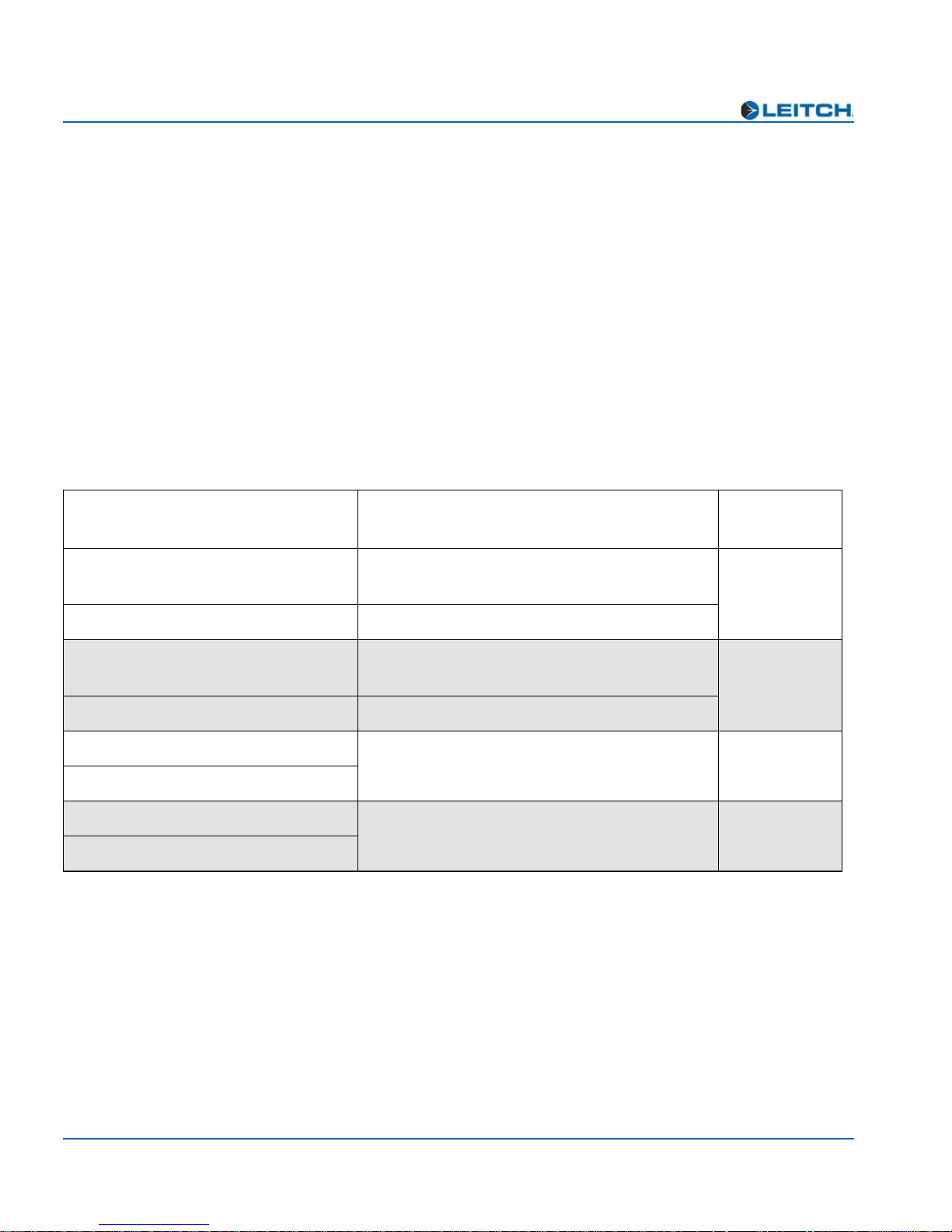
Table 1-1. Descriptions of the AVM-3901-B, -C, -B4, and -C4 Modules
Input Output
Digital video SDI 525/625 Digital video SDI 525/625 with multiplexed
audio
Two-channel AES digital audio (110Ω) Two-channel AES processed audio (110Ω)
Digital video SDI 525/625 Digital video SDI 525/625 with multiplexed
audio
Two-channel AES digital audio (75Ω) Two-channel AES processed audio (75Ω)
Digital video SDI 525/625 Digital video SDI 525/625 with multiplexed
audio
Four-channel AES digital audio (110Ω)
Digital video SDI 525/625 Digital video SDI 525/625 with multiplexed
audio
Four-channel AES digital audio (75Ω)
AVM-3901
Version
AVM-3901-B
AVM-3901-C
AVM-3901-B4
AVM-3901-C4
2 AVM-3901-B, -C, -B4, and -C4 Installation and Operation Manual
Page 15

Main Features
Chapter 1: Introduction
AVM-3901-B, -C, -B4, and -C4 modules have the following main
features:
• SDI video input with auto-detect
• Two SDI video outputs
• Internal video frame synchronizer
• Two AES input channels (-B and -C versions) or four AES input
channels (-B4 and -C4 versions)
• Two AES processed output channels (-B and -C versions)
• Unbalanced DARS input (-B and -C versions) with additional
jumper-selectable balanced input on the -B version
• Audio delay
• Audio tracking capability
• Genlock reference input with loop-through
• Internal audio processing amplifier
• 16-, 20-, or 24-bit audio processing
• Selectable silence for all audio channels
• Audio re-sampling for 32 kHz to 108 kHz AES inputs, with bypass
for data over AES operation
• C-, U-, and V-bit transparency
• Compressed data pass
• Capability for control via card-edge, remote control panels, and
GUI applications such as CCS Pilot™ (3901RES-E resource
module is required for Ethernet and control panel use)
AVM-3901-B, -C, -B4, and -C4 Installation and Operation Manual 3AVM-3901-B, -C, -B4, and -C4
Page 16

Chapter 1: Introduction
Front and Back Modules
Front Module
NEO front modules are designated by the suffix “-FM.” For example,
Note
The DARS Present LED is not
currently functional on the
AVM-3901-B4 and -C4
versions.
Escape button
the front module of the AVM-3901-B is the “AVM-3901-B-FM.”
Figure 1-1 illustrates the position of the LEDs on the front modules of
the AVM-3901-B, -C, -B4, and -C4.
Front view
64 X 16 VFD submodule
Local/Remote switch
(hidden behind extractor)
Card extractor
Nav+/Nav- switch
Visible display area
Enter button
(up/down)
Top view
)
l
)
l
a
a
n
n
o
i
o
t
)
n
e
e
)
l
)
a
n
n
e
o
i
e
t
r
c
g
(
n
t
u
f
n
t
e
o
s
n
e
(
r
r
p
o
I
r
r
D
S
E
r
g
(
t
n
e
)
s
e
w
r
o
l
p
)
)
l
n
n
e
e
e
e
y
c
(
e
e
n
r
r
e
e
g
g
r
z
(
(
e
e
f
5
5
e
e
r
2
2
F
6
R
5
LEDs
i
t
)
n
e
e
r
g
(
d
e
k
c
o
l
e
c
n
e
r
e
f
e
R
c
c
n
n
u
f
u
)
f
t
n
t
o
e
o
n
e
(
)
n
r
(
r
d
g
r
(
o
e
r
r
o
t
r
(
r
n
r
e
r
e
e
o
c
s
r
d
n
r
e
r
e
y
e
p
s
b
)
k
n
a
l
B
(
d
o
m
S
e
i
e
b
R
d
e
A
u
m
D
A
D
E
(only available in -B and -C versions)
Standard module indicators
Local
Remote
Nav +
Nav -
Enter
Esc
Major
Alarm
Majo
r
Alar
m
Mino
Alar
Minor
Alarm
Local/Remote switch
Powe
r
Power
Module
Status
Module
Status
r
m
SW1
Escape button
Figure 1-1. Card-Edge Controls of the AVM-3901-B, -C, -B4, and -C4-FM Front Modules
4 AVM-3901-B, -C, -B4, and -C4 Installation and Operation Manual
Nav+/Nav- switch
(up/down)
Enter button
Card extractor
Page 17

Back Modules
Note
The input DARS connectors on
the AVM-3901-B4-BM and
AVM-3901-C4-BM back
modules are not currently
functional.
Chapter 1: Introduction
In NEO frames, back modules are placed directly behind the front
modules. Back modules are designated by the suffix “-BM.” For
example, the back module of the AVM-3901-B is the
“AVM-3901-B-BM.” See Figures 1-2 to 1-5 for illustrations of the
AVM-3901-B, -C, -B4, and -C4-BM back modules.
GENLOCK
LOOP
INPUT
DARS
BALANCED AES IN/OUT DARS INPUT
Figure 1-2. AVM-3901-B-BM Back Module
GENLOCK
LOOP
INPUT
DARS
OUT 1
AES
OUT 2
AES
Figure 1-3. AVM-3901-C-BM Back Module
GENLOCK
LOOP
INPUT
DARS
BALANCED AES/DARS INPUT
Figure 1-4. AVM-3901-B4-BM Back Module
IN 1
AES
IN 2
AES
OUT 1 INPUT
SDI SDI
OUT 1
SDI
OUT 1 INPUT
SDI SDI
OUT 2
SDI
OUT 2
SDI
OUT 2
SDI
INPUT
SDI
AVM-3901-B
AVM-3901-C
AVM-3901-B4
GENLOCK
LOOP
INPUT
DARS
Figure 1-5. AVM-3901-C4-BM Back Module
AVM-3901-B, -C, -B4, and -C4 Installation and Operation Manual 5AVM-3901-B, -C, -B4, and -C4
IN 1
AES
IN 2
AES
IN 3
AES
IN 4
AES
OUT 1
SDI
OUT 2
SDI
INPUT
SDI
AVM-3901-C4
Page 18

Chapter 1: Introduction
AES 2
Back Module Pinouts
Figure 1-6 and Figure 1-7 show the pinouts for the Balanced AES In/
Out DARS Input connector on the AVM-3901-B-BM module, and the
Balanced AES/DARS Input connector on the AVM-3901-B4-BM back
module.
13
25
DARS in
- G +
- +
AES 1 out
out
- +
GND
- +
AES 1 in
- +
- G +
AES 2 in
GND
1
- G +- G +
- G +
14
Figure 1-6. Pinouts on the AVM-3901-B-BM (Back Module)
13
25
- G +
AES 1 in
- +
- +
GND
- +
- +
AES 2 in
- G +
AES 3 in
- G +- G +
GND
1
- G +
14
AES 4 in
Figure 1-7. Pinouts on the AVM-3901-B4-BM (Back Module)
6 AVM-3901-B, -C, -B4, and -C4 Installation and Operation Manual
Page 19

Plug-In Adapter
Note
The AIB-25-3901MF is a
universal adapter. Some
terminals on this adapter are not
used with the AVM-3901-B-BM
and the AVM-3901-B4-BM
back modules.
Chapter 1: Introduction
The balanced AVM-3901-B-BM and AVM-3901-B4-BM back modules
are shipped with a detachable plug-in adapter (AIB-25-3901MF). This
adapter provides terminals for connecting twisted pair audio cables
directly to the back module. Figure 1-8 illustrates the pinouts and screw
terminals for the plug-in adapter.
AES 2 output
AES 1 output
DARS input
AES 2 out
G - +
AES 1 in
G + -
AES 1 input
AES 2 in
G + -
AES 1 out
G - +
AES 3 out
G + -
AES 3 in
G + -
AIB-25-3901MF
G - +
G + -
AES 2 input
G + -
DARS
AES 4 out
AES 4 in
AVM-3901-B
DB2 male
connector
connector
DB2 female
front module
Audio processing
Figure 1-8. AIB-25-3901MF Balanced Input/Output Connections for the AVM-3901-B-BM
AVM-3901-B, -C, -B4, and -C4 Installation and Operation Manual 7AVM-3901-B, -C, -B4, and -C4
Page 20

Chapter 1: Introduction
AES 2 out
G - +
AES 1 in
G + -
AES 1 input
AES 2 input
AES 2 in
G + -
AES 1 out
G - +
AES 3 out
G + -
AES 3 in
G + -
AIB-25-3901MF
G - +
G + -
AES 3 input
G + -
DARS
AES 4 out
AES 4 in
DB2 male
connector
AES 4 input
AVM-3904-B4
connector
DB2 female
front module
Audio processing
Figure 1-9. AIB-25-3901MF Balanced Input/Output Connections for the AVM-3902-B4-BM
8 AVM-3901-B, -C, -B4, and -C4 Installation and Operation Manual
Page 21

Signal Flow
A
2
Audi
AVM-3901-B and AVM-3901-C
Figure 1-10 is a functional block diagram of the AVM-3901-B and the
AVM-3901-C modules
Chapter 1: Introduction
o tracking
SDI in
AES in 1
AES in 2
Genlock
Re-
clock
Video
frame
sync
Audio
rate
converter
CPU
control
Audio
mux
udio
proc
Figure 1-10. .Functional Block Diagram of the AVM-3901-B and -C Modules
SDI 1
SDI 2
AES out 1
AES out
AVM-3901-B, -C, -B4, and -C4 Installation and Operation Manual 9AVM-3901-B, -C, -B4, and -C4
Page 22

Chapter 1: Introduction
A
AVM-3901-B4 and -C4
Figure 1-11 is a functional block diagram of the AVM-3901-B4 and the
AVM-3901-C4 modules
Audio tracking
SDI in
AES 1 in
AES 2 in
AES 3 in
AES 4 in
NTSC or PAL
composite
analog reference
Re-clock
Genlock
Audio
rate
converter
CPU
Control
udio
processor
Figure 1-11. .Functional Block Diagram of the AVM-3901-B4 and C4 Modules
SDI 1
SDI 2
10 AVM-3901-B, -C, -B4, and -C4 Installation and Operation Manual
Page 23

Overview
Caution
Before installation, please read
the NEO Safety Instructions and
Precautions Manual. This
document contains important
information about the safe
installation and operation of
NEO products.
Chapter 2
Installation and Removal
Installation, navigation, configuration, and setup information is now
included in the NEO FR-3901, FR-3903, and FR-3923 Mounting
Frames Installation and Operation Manual. If your current NEO frame
manual is Edition A, B, C, or D, you will need to download an updated
version from the Leitch Web site (www.leitch.com
information.
In this chapter, you can find information on the following topics:
• “Packing List” on page 12
) to access this
• “Installing AVM-3901-B, -C, -B4, and -C4 Modules” on page 12
• “Removing AVM-3901-B, -C, -B4, and -C4 Modules” on page 12
• “Setting Jumpers” on page 13
• “Audio Tracking Pairs” on page 14
• “Upgrading AVM-3901-B, -C, -B4, and -C4 Firmware” on page 15
• “Correcting a Failed Upgrading Procedure” on page 19
AVM-3901-B, -C, -B4, and -C4 Installation and Operation Manual 11
Page 24

Chapter 2: Installation and Removal
Packing List
Each NEO AVM-3901-B, -C, -B4, and -C4 module package includes
the following items:
• One AVM-3901-B, C, B4, or C4-FM front module
• One AVM-3901-B, C, B4, or C4-BM back module
• One AIB-25-3901MF plug-in adapter (AVM-3901-B and
AVM-3901-B4 modules only)
•One AVM-3901-B, -C, -B4, and -C4 Multiplexers/Synchronizers
Installation and Operation Manual per order
Installing AVM-3901-B, -C, -B4, and -C4
Modules
This module requires no specialized installation procedures. For general
information about installing NEO modules, see your NEO FR-3901,
FR-3903, and FR-3923 Mounting Frames Installation and Operation
Manual.
For information on audio tracking pairs, and installing cooperative
modules together, see “Audio Tracking Pairs” on page 14.
Removing AVM-3901-B, -C, -B4, and -C4
Modules
This module requires no specialized removal procedures. For general
information about removing NEO modules, see your NEO FR-3901,
FR-3903, and FR-3923 Mounting Frames Installation and Operation
Manual.
12 AVM-3901-B, -C, -B4, and -C4 Installation and Operation Manual
Page 25

Setting Jumpers
Two jumpers, labelled J8 and J9, are located near the back of the
AVM-3901-FM front modules. These jumpers determine the settings
for the DARS inputs. DARS is currently only functional in the -B and
-C versions of the AVM-3901 modules.
Figure 2-1 shows the location of the jumpers on the module. A triangle
symbol beside the jumpers indicates Pin 1.
Chapter 2: Installation and Removal
J8 and J9
jumper pins
AVM-3901-B, -C, -B4, and -C4 Installation and Operation Manual 13
Figure 2-1. Location of J8 and J9 Jumper Pins
Table 2-1. Jumper Positions (J8 and J9)
DARS Input J8 and J9 Jumper Positions
Balanced Input Both jumpers set to Pins 1 and 2
Unbalanced Input Both jumpers set to Pins 2 and 3
Page 26

Chapter 2: Installation and Removal
Audio Tracking Pairs
Selected audio and video NEO modules are designed to connect to each
other in audio tracking pairs. This feature provides audio-to-video
synchronization and delay with tracking capability. External
connections are not required for this feature.
The AVM-3901-B, -C, -B4, and -C4 modules can be used as part of an
audio tracking pair. To use this feature, install the AVM-3901-B, -C,
-B4, and -C4 video modules directly above the audio module.
Alternately, install the AVM-3901-B, -C, -B4, and -C4 modules at the
bottom of column one in the frame, with the audio module at the top of
column two.
The audio-tracking pairs feature can be enabled or disabled. See
DnBusEn (down bus enable) in the Operator and All List, or the Tree
View Parameter List.
The following table lists the audio tracking pairs in which the
AVM-3901-B, -C, -B4, and -C4 can be used. Use this table to help plan
where to install your modules.
Table 2-2. Audio Tracking Pairs Details
Input Output
Digital video SDI 525/625 Digital video SDI 525/625 with
multiplexed audio
Four-channel AES digital audio (110
Digital video SDI 525/625 Digital video SDI 525/625 with
Four-channel AES digital audio (75Ω) Four-channel AES digital audio (75Ω) MSA-3901-C
Digital video SDI 525/625 Digital video SDI 525/625 with
Eight-channel AES digital audio (110
Ω) Four-channel AES digital audio (110Ω) MSA-3901-B
multiplexed audio
multiplexed audio
Ω) MSA-3901-B4
Audio Tracking
Pair
AVM-3901-B
AVM-3901-C
AVM-3901-B4
Digital video SDI 525/625 Digital video SDI 525/625 with
Eight-channel AES digital audio (75Ω) MSA-3901-C4
14 AVM-3901-B, -C, -B4, and -C4 Installation and Operation Manual
AVM-3901-C4
multiplexed audio
Page 27

Chapter 2: Installation and Removal
Upgrading AVM-3901-B, -C, -B4, and -C4
Firmware
Firmware upgrading is a routine procedure that you must perform to
install newer versions of software on the AVM-3901-B, -C, -B4, and
-C4 modules. Pilot, Co-Pilot, or Navigator software applications are
required for this procedure. You can use either the Discovery or the
drag-and-drop method. When performing the upgrading procedure,
check the appropriate readme file to confirm which files are needed.
Use care to ensure that you upload the correct files to the intended
module.
If for some reason the upgrade fails, the module may not respond to
controls and will appear to be non-functional. In that event, follow the
procedures described in “Correcting a Failed Upgrading Procedure” on
page 19.
Upgrading the Firmware (Discovery Method)
Follow these steps to upgrade the firmware using the Discovery
method:
1. Download the most recent appropriate upgrade package from the
Leitch Web site or from your CD-ROM, and then unzip the upgrade
package.
2. If the affected module has not been discovered, perform the
Discovery operation, as described in your CCS software
application manual or online help.
3. Double-click the device icon.
The Configuration... window opens. On the Software Upgrade
tab, the /slotx/boot (where x is the slot number) directory appears
in the Select the device directory to transfer to: field.
4. Click Add, and in the Add Upgrade Files box, browse and select
the boot folder in the module’s upgrade; click OK.
The Add Upgrade Files box appears.
5. Select the file and then click OK.
AVM-3901-B, -C, -B4, and -C4 Installation and Operation Manual 15
6. Click Perform Transfer and then click Yes .
This may take several minutes.
Page 28

Chapter 2: Installation and Removal
7. Wait for the message File transfer to device succeeded in the
If an fl0 folder is included in the .zip file, the files within that folder
must now be uploaded as shown below. (In some cases, the readme file
may indicate other separate files must be uploaded instead.)
Follow these steps to upload the remaining files:
1. On the Software Upgrade tab, select the /slotx/fl0 (where x is the
2. Click Add, and in the Add Upgrade Files box, browse and select
3. Click OK.
4. Select the files shown in the Add Upgrade Files box, and then
Caution
You must delete unwanted files
in the Add upgrade files for
transfer to device: field before
transferring the files. Otherwise,
the upgrading procedure will
fail.
5. Select and delete unwanted files (for example: vxWorks.lzs) in the
6. Click Perform Transfer and then click Yes .
7. Wait for the message File transfer to device succeeded.
status bar.
slot number) directory in the Select the device directory to
transfer to: field.
the fl0 folder in the module’s upgrade package.
click OK.
Add upgrade files for transfer to device: field by clicking
Remove.
This may take a moment.
8. Click Reboot Device and then click Yes.
9. Wait 30 seconds, and then close the Configuration... box.
The module name appears at the card edge.
16 AVM-3901-B, -C, -B4, and -C4 Installation and Operation Manual
Page 29

Chapter 2: Installation and Removal
Upgrading the Firmware (Drag-and-Drop Method)
Follow these steps to upgrade the firmware using the drag-and-drop
method:
1. Download the appropriate most recent upgrade package from the
Leitch Web site or from your CD-ROM, and then unzip the upgrade
package.
2. If the affected module has not been discovered by your CCS
software application, enter the Build mode, and then drag or copy
and paste the module’s device icon from the catalog folder into the
Network or Discovery folder.
3. Right-click the device icon and then select Properties.
4. On the NRO or Device tab of the Navigation Properties box, enter
the IP address of the frame that holds the module. (See Figure 2-2.)
Caution
Do not make changes in the
third field (located above and to
the right of the Set Default
button.)
Enter frame IP number here
Do not make changes in
this field
Figure 2-2. Navigation Properties Box
5. In the last field, enter the slot number of the module, and then close
the window.
6. Double-click the device icon.
AVM-3901-B, -C, -B4, and -C4 Installation and Operation Manual 17
The Configuration... window opens. On the Software Upgrade
tab, the /slotx/boot (where x is the slot number) directory appears
in the Select the device directory to transfer to: field.
7. Click Add, and in the Add Upgrade Files box, browse and select
the boot folder in the module’s upgrade.
Page 30

Chapter 2: Installation and Removal
8. Click OK.
9. Select the file and then click OK.
10. Click Perform Transfer and then click Ye s.
11. Wait for the message File transfer to device succeeded in the
If an fl0 folder is included in the .zip file, the files within that folder
must now be uploaded as shown below. (In some cases, the readme file
may indicate other separate files must be uploaded instead.)
Follow these steps to upload the remaining files:
1. On the Software Upgrade tab, select the /slotx/fl0 (where x is the
The Add Upgrade Files box appears.
This may take several minutes.
status bar.
slot number) directory in the Select the device directory to
transfer to: field.
Caution
You must delete unwanted files
in the Add upgrade files for
transfer to device: field before
transferring the files. Otherwise,
the upgrading procedure will
fail.
2. Click Add, and in the Add Upgrade Files box, browse and select
the fl0 folder in the module’s upgrade package.
3. Click OK.
4. Select the files shown in the Add Upgrade Files box, and then
click OK.
5. Select and delete unwanted files (for example: vxWorks.lzs) in the
Add upgrade files for transfer to device: field by clicking
Remove.
6. Click Perform Transfer and then click Yes .
7. Wait for the message File transfer to device succeeded.
This may take a moment.
8. Click Reboot Device and then click Yes.
9. Wait 30 seconds and then close the Configuration... box.
The module name appears at the card edge.
18 AVM-3901-B, -C, -B4, and -C4 Installation and Operation Manual
Page 31

Chapter 2: Installation and Removal
Correcting a Failed Upgrading Procedure
Firmware upgrades may fail in the event of network interruptions,
power failures, or if too much data is uploaded to the NEO module.
Often, uploads of too much data can occur for one of the following
reasons:
• The boot file (typically vxWorks.lzs) was accidentally uploaded
during the fl0 procedure, instead of the boot procedure.
• Files were sent to the wrong NEO module.
• The particular hardware version of the module requires only some
(but not all) of the available fl0 files.
• The upgrade .zip file was mistakenly sent to the module.
All of these problems can be corrected by re-installing the firmware
while in a fail-safe mode, as described in the following pages. When
you are performing this procedure, check the appropriate readme file to
confirm which files are needed. Use care to ensure that you upload the
correct files to the intended module.
Setting the Module to Fail-Safe Loader Mode
Follow these steps to set a NEO module to the fail-safe loader mode:
1. Remove the affected module from the NEO frame.
2. Press the Nav switch down while simultaneously pressing both the
Escape and Enter buttons.
3. While still pressing the buttons and the navigation switch, reinsert
the module into the frame and hold for approximately three seconds
until the display on the module reads Offline-H (or Offline-L)
Upload Required.
Upgrading the Firmware in Fail-Safe Mode
Follow these steps to upgrade the firmware in the fail-safe mode:
Note
To successfully upgrade the
firmware, you must follow these
steps in the exact sequence
described.
1. Download the most recent appropriate upgrade package from the
Leitch Web site or from your CD-ROM, and then unzip the upgrade
package.
AVM-3901-B, -C, -B4, and -C4 Installation and Operation Manual 19
Page 32

Chapter 2: Installation and Removal
2. If the affected module has not been discovered by your CCS
3. Right-click the device icon and then select Properties.
4. On the NRO or Device tab of the Navigation Properties box, enter
software application, enter the Build mode, and then drag or copy
and paste the module’s device icon from the catalog folder into the
Network or Discovery folder.
the IP address of the frame that holds the module. (See Figure 2-3.)
Caution
Do not make changes in the
third field (located above and to
the right of the Set Default
button.)
Enter frame IP number here
Do not make changes in
this field
Figure 2-3. Navigation Properties Box
5. In the last field, enter the slot number of the module, and then close
the window.
6. Double-click the device icon.
The Configuration... box opens. On the Software Upgrade tab,
the /slotx/boot (where x is the slot number) directory appears in the
Select the device directory to transfer to: field.
7. Click Add, and in the Add Upgrade Files box, browse and select
8. Click OK.
9. Select the file and then click OK.
10. Click Perform Transfer and then click Ye s.
11. Wait for the message File transfer to device succeeded in the
20 AVM-3901-B, -C, -B4, and -C4 Installation and Operation Manual
the boot folder in the module’s upgrade.
This may take several minutes.
status bar.
Page 33

Rebooting the Module
Follow these steps to reboot the affected NEO module:
Note
Some NEO modules will reboot
automatically. In these cases,
the Reboot button will be
grayed out. During this time, the
module’s card-edge display will
show the word Rebooting
before the name of the module
appears. These modules do not
require the fl0 file.
1. Click Reboot Device, and then click Ye s.
After the module has rebooted, a message box advises you to wait
until the device has rebooted.
2. Wait 30 seconds.
3. On the Software Upgrade tab, select the /slotx/fl0 (where x is the
slot number) directory in the Select the device directory to
transfer to: field.
4. Click Add, and then browse and select the fl0 folder in the
module’s upgrade package.
5. Click OK.
6. Select the files shown in the Add Upgrade Files box, and then
click OK.
Chapter 2: Installation and Removal
Caution
You must delete unwanted files
in the Add upgrade files for
transfer to device: field before
transferring the files. Otherwise,
the upgrading procedure will
fail.
7. Select and delete unwanted files (for example: vxWorks.lzs) in the
Add upgrade files for transfer to device: field by clicking
Remove.
8. Click Perform Transfer and then click Yes .
9. Wait for the message File transfer to device succeeded.
This may take a moment.
10. Click Reboot Device and then click Yes.
11. Wait 30 seconds, and then close the Configuration... box.
The module name appears at the card edge.
AVM-3901-B, -C, -B4, and -C4 Installation and Operation Manual 21
Page 34

Chapter 2: Installation and Removal
22 AVM-3901-B, -C, -B4, and -C4 Installation and Operation Manual
Page 35

Overview
Chapter 3
Operation
Installation, navigation, configuration, and setup information is now
included in the NEO FR-3901, FR-3903, and FR-3923 Mounting
Frames Installation and Operation Manual. If your current NEO frame
manual is Edition A, B, C, or D, you will need to download an updated
version from the Leitch Web site (www.leitch.com
information.
) to access this
This chapter describes how to operate the AVM-3901-B, -C, -B4, and
-C4 modules using card-edge controls.
The following topics are found in this chapter:
• “Operational Notes” on page 24
• “Cross-Functional Parameter Changes” on page 28
• “Navigating the Operator and All Lists” on page 31
• “Operator and All List Parameters” on page 32
• “Setup Parameters” on page 39
• “Alarms” on page 40
• “State Recovery Parameter Availability” on page 42
• “LEDs and Module Indicators” on page 43
AVM-3901-B, -C, -B4, and -C4 Installation and Operation Manual 23
Page 36

Chapter 3: Operation
Operational Notes
When using the AVM-3901-B, -C, -B4, and -C4 module, observe the
Note
If you do not observe these
“Operational Notes,” you may
accidentally change your
parameter settings.
following operational notes:
• If you change parameters within 16 seconds after the
AVM-3901-B, -C, -B4, or -C4 banner first appears on the VFD,
your changes will not be saved. Parameter changes that you make
after this 16-second delay will be saved and restored if the module
loses power and must be restarted.
• Although the effect of a parameter change may appear to be
immediate, the module requires 20 seconds to save the latest
change. If another change is made during these 20 seconds, the first
parameter change and the second parameter change will not be
saved until 20 seconds after the second parameter change. There is
no limit to the number of changes that can be made within 20
seconds of each other. However, none of these changes will be
saved until 20 seconds after the last parameter change.
• When you set the FctryRcl (factory recall) parameter to Ye s , the
module takes several seconds to reset all of the parameters. (Setup
parameters are not affected by this factory recall mode.) The lists of
“Operator and All List Parameters” on page 32 and “Tree View
Parameters” on page 57 indicate parameter default settings that are
restored when FctryRcl is set to Ye s .
24 AVM-3901-B, -C, -B4, and -C4 Installation and Operation Manual
Page 37

PCM and Non-PCM Processing
On the AVM-3901-B, -C, -B4, and -C4 modules, the AESxFormat
parameters provide the ability to select either PCM or Non-PCM as
input formats. Table 3-1 lists the available selections for each OutxSrc
parameter when you select PCM.
Table 3-1. OutxSrc Selections for PCM Processing
Chapter 3: Operation
Available Selection in
OutxSrc Parameter
AES1a All
AES1b All
AES2a All
AES2b All
AES3a AVM-3901-B4 and -C4
AES3b AVM-3901-B4 and -C4
AES4a AVM-3901-B4 and -C4
AES4b AVM-3901-B4 and -C4
Mute All
AES1 Sum All
AES2 Sum All
AES3 Sum AVM-3901-B4 and -C4
Modules Affected
AVM-3901-B, -C, -B4, and -C4 Installation and Operation Manual 25
AES4 Sum AVM-3901-B4 and -C4
However, if you select Non-PCM for one of the AESxFormat
parameters, its summation (AESxSum) is not a valid selection. For
example, if you set AES2Format to Non-PCM, AES2Sum is not a valid
selection. The handling of this selection is described on page 27.
Page 38

Chapter 3: Operation
PCM Processing
In PCM processing, if you select AES1 Sum, AES2 Sum, AES3 Sum,
or AES4 Sum as the source, the result is the sum of the two parts of the
AES channel, divided by two. (AES3 Sum and AES4 Sum are available
only on the AVM-3901-B4 and -C4 modules.)
For example:
AES1 Sum = (AES1a + AES1b) ÷ 2
Thus, a stereo pair is averaged out, creating a mono signal.
See Figure 3-1 for an illustration of this process.
Mute
AES1
AES2
AES3
4
C
-
s
d
n
n
o
i
a
4
B
v
-
AES4
s
r
e
AES1
AES2
AES3
4
C
-
s
d
n
n
o
i
a
s
AES4
r
4
e
B
v
-
AES1a
AES1b
AES2a
AES2b
AES3a
AES3b
AES4a
AES4b
AES1a
AES1b
AES2a
AES2b
AES3a
AES3b
AES4a
AES4b
(A+B)/2
(A+B)/2
(A+B)/2
(A+B)/2
AES1sum
AES2sum
AES3sum
AES4sum
.
.
.
A
1
0
S
E
A
.
.
3
0
S
E
A
t
u
o
2
0
E
S
u
t
o
.
t
u
o
AES1
o
AES2
.
.
.
AES8
u
t
1
S
E
6
A
Audio MUX - PCM Operation
Figure 3-1. PCM Processing of the Audio Mux Signal
26 AVM-3901-B, -C, -B4, and -C4 Installation and Operation Manual
Page 39

Non-PCM Processing
Compressed non-PCM audio signals cannot be summed and averaged
out. Therefore, if you select one of these options, the sources that
appear in the Out01Src to Out16Src parameters are arbitrarily matched
odd/even to left/right.
See Figure 3-2 for an example of non-PCM processing.
Mute
AES1
AES2
AES3
4
C
-
s
d
n
n
o
i
a
s
AES4
r
4
e
B
v
-
AES1
AES1a
AES1b
AES2a
AES2b
AES3a
AES3b
AES4a
AES4b
AES1
.
AES1
.
.
AES1b AES1sum
AES1a
AES1b
.
.
.
AES1sumAES1a
AES1sum
AES1sum
Chapter 3: Operation
AES16out
.
.
.
AES03out
2
o
u
t
A
S
0
E
t
o
u
0
1
S
E
A
.
.
AES1
.
AES2
.
.
AES8
.
AES2
.
.
.
AES2
AES2
s
n
o
i
s
r
AES3
e
v
4
C
-
d
n
a
4
B
-
AES4
AES2b AES2sum
AES3
.
.
.
AES3
AES3b AES3sum
AES4
.
.
.
AES4
AES4b
AES2a
AES3a
AES4a
AES2b
AES3b
AES4b
AES2sumAES2a
AES3sumAES3a
AES4sumAES4a
.
.
.
.
.
.
AES4sum
.
AES2sum
.
AES3sum
.
AES4sum
AES1sum
AES3sum
AES1sum
Audio MUX - NonPCM Operation
Figure 3-2. Non-PCM Processing of the Audio Mux Signal
AVM-3901-B, -C, -B4, and -C4 Installation and Operation Manual 27
Page 40

Chapter 3: Operation
Cross-Functional Parameter Changes
When making selections in specific parameters, you force changes to
occur in other parameters. Tables 3-2 to 3-5 list the cross-functional
parameter changes for AVM-3901-B, -C, -B4, and -C4 modules.
Audio Parameters
Table 3-2 describes forced settings and disabled parameters that result
when you select specific audio parameters.
Table 3-2. Audio Parameters
Condition Forced Setting Disabled Parameters
AES1Format = Non-PCM
AES2Format = Non-PCM
AES3Format = Non-PCM
(-B4 and -C4 versions)
AES4Format = Non-PCM
(-B4 and -C4 versions)
• Gain_1A = 0
• Gain_1B = 0
•Invert1A = No
•Invert1B = No
• Gain_2A = 0
• Gain_2B = 0
•Invert2A = No
•Invert2B = No
• Gain_3A = 0
• Gain_3B = 0
•Invert3A = No
•Invert3B = No
• Gain_4A = 0
• Gain_4B = 0
•Invert4A = No
•Invert4B = No
• Gain_1A
• Gain_1B
• Invert1A
• Invert1B
• Gain_2A
• Gain_2B
• Invert2A
• Invert2B
• Gain_3A
• Gain_3B
• Invert3A
• Invert3B
• Gain_4A
• Gain_4B
• Invert4A
• Invert4B
ALOVMode = Mute &
SdiPrsnt= No
ASBypass = Yes TrackVid = No TrackVid
Any of Out01Src to Out16Src
set to a Non-PCM format input
source
28 AVM-3901-B, -C, -B4, and -C4 Installation and Operation Manual
Out01Src-Out16Src = Mute Out01Src to Out16Src
TrackVid = No TrackVid
Page 41

Frame Synchronization Function (FSFunction)
Table 3-3 lists the disabled parameters resulting from one of the
selections of the FSFunction parameter.
Table 3-3. Frame Synchronization Function
Condition Disabled Parameter
Chapter 3: Operation
FSFunctn = bypass
•VPhase
•HPhase
• VLOV_Mode
•FrzType
• ForceFrz
•VidFrzn
•FSMode
Frame Synchronization Mode (FSMode)
Table 3-4 lists the disabled parameter resulting from one of the
selections of the FSMode parameter.
Table 3-4. Frame Synchronization Mode
Condition Forced Setting Disabled Parameter
FSMode = DLYMode TrackVid = No TrackVid
AVM-3901-B, -C, -B4, and -C4 Installation and Operation Manual 29
Page 42

Chapter 3: Operation
SDI Input Video Standard (SdiStdSet)
Table 3-5 lists the options and ranges that are affected by the SDI input
standard.
Table 3-5. SDI Input Video Standards
Parameters Affected by the SDI
Input Standard
Parameter ID
VPhase Vertical Phase
HPhase Horizontal Phase
SdiStdFb SDI Standard
Parameter
Name
Feedback
SDI Input Standard
Auto D1-525 D1-625
• Unknown: previous range
• D1-525: 0 to 524 lines
• D1-625: 0 to 624 lines
• Unknown: previous range
• D1-525: 0 µs to 63.518 µs
• D1-625: 0 µs to 63.963 µs
• Unknown
• D1-525
• D1-625
0 to 524 lines 0 to 624 lines
0 µs to
63.518 µs
D1-525 D-625
0 µs to
63.963 µs
30 AVM-3901-B, -C, -B4, and -C4 Installation and Operation Manual
Page 43

Navigating the Operator and All Lists
To navigate, and then view or change a parameter from the Operator
and All Lists, follow these steps:
1. Open the front panel of the NEO frame.
2. Press any card-edge control to turn on the VFD screen.
The message AVM-3901-B, -C, -B4, or -C4 appears. If a previous
user has left the display at a different parameter name, repeatedly
press the Escape button until the message AVM-3901-B, -C, -B4,
or -C4 appears.
3. Push the Enter button.
Note
After several seconds of
inactivity, a scrolling message
will appear, describing the
purpose of the currently selected
parameter.
The name of the first parameter option in the list appears.
4. Push the Enter button again to access the options for the parameter
displayed on the VFD screen.
OR
Press the Nav+/Nav- switch down repeatedly to view other
parameters, and then press Enter to access an item’s parameter
options.
Chapter 3: Operation
5. Press the Nav+/Nav- switch up or down to scroll through the
different selectable parameter options, and then press Enter to
select the value you want.
OR
Press the Nav+/Nav- switch up or down to adjust the numeric
parameter value, and then press Enter.
6. Close the front panel of the frame to ensure the cooling system
continues to operate properly.
AVM-3901-B, -C, -B4, and -C4 Installation and Operation Manual 31
Page 44

Chapter 3: Operation
Operator and All List Parameters
This complete list of parameter settings is arranged so that the settings
Note
You can reset the default values
for all of the parameters
automatically via the FctryRcl
parameter, found in this table.
most likely requiring changes are placed at the top of the list. Items on
the bottom of the list are the least likely to require changing. Parameters
with the designation [RO] are “read-only.” An asterisk (*) indicates the
default user range or value.
The All List is a long flat list of all the available parameters, arranged
from the most-used to least-used. It is intended for a “Supervisor”
security designation. The Operator List is a condensed version of the
All List, and is intended for an “Operator” security designation. The
following table shows all available parameters. Parameters accessed
only from within the All List are shaded in gray.
See “Navigating the Operator and All Lists” on page 31 for instructions
on navigating this list using card-edge controls.
Table 3-6. Operator and All List Parameters
Card-Edge
ID
SdiStdSet Serial Digital Interface
SdiStdFb
[RO]
SdiPrsnt
[RO]
EdhErrPI Error Detection and
EdhErrPrsnt
[RO]
EdhErrCnt
[RO]
Parameter Name Function User Range
Selects the line standard for the incoming
Input Video Standard Set
Serial Digital Interface
Input Video Standard
Feedback
Serial Digital Interface
Input Video Present
Handling Error Poll
Error Detection and
Handling Present
Error Detection and
Handling Error Counter
digital video
Returns the SDI input video signal standard
Returns the presence of the SDI input signal
Defines the polling interval for the EDH
error detection
Returns the presence of EDH from the input
SDI signal
Returns the number of occurred EDH errors 0 to 16777215
•Auto*
• D1-525
• D1-625
• Unknown
• D1-525
• D1-625
•No
•Yes
0 s to 14400 s
(1 s*)
•No
•Yes
errors (clip)
32 AVM-3901-B, -C, -B4, and -C4 Installation and Operation Manual
Page 45

Table 3-6. Operator and All List Parameters (Continued)
Chapter 3: Operation
Card-Edge
ID
EdhErrClr Error Detection and
AES_Prsnt
[RO]
Parameter Name Function User Range
Handling Error Clear
AES1 to AES4 In Present
(AES3 And AES4 are only
available in -B4 and -C4
versions)
Clears the EDH error counter
Detects the presence of signal at
inputs 1 to 4
(AES3 and AES4 are only available in
-B4 and -C4 versions)
•No*
•Yes
• ====
• 1===
• =2==
•12==
• ==3=
• 1=3=
•=23=
•123=
• ===4
• 1==4
•=2=4
•12=4
• ==34
•1=34
• =234
•1234
-B and -C
versions only:
•==
•1=
•=2
•12
AES1Format
to
AES4Format
Delay_1A,
Delay_1B,
Delay_2A,
Delay_2B
AVM-3901-B, -C, -B4, and -C4 Installation and Operation Manual 33
AES1 to AES 4 In Data
Format
(AES3format and
AES4format are only
available in -b4 and -c4
versions)
Delay: AES1 in A to Delay:
AES2 in B
Selects the input format for data inputs 1 to
4
(AES3Format and AES4Format are only
available in -B4 and -C4 versions)
Adjusts delay for AES1 in channel A to
AES2 in channel B
•PCM*
•Non-PCM
0* msec to
1320.00 msec
Page 46

Chapter 3: Operation
Table 3-6. Operator and All List Parameters (Continued)
Card-Edge
ID
Delay_3A,
Delay_3B,
Delay_4A,
Delay_4B
(-B4 and -C4
versions)
Gain_1A,
Gain_1B,
Gain_2A,
Gain_2B
Gain_3A,
Gain_3B,
Gain_4A,
Gain_4B
(-B4 and -C4
versions only)
Invert1A,
Invert1B,
Invert2A,
Invert2B
Parameter Name Function User Range
Delay: AES3 in A to Delay:
AES4 in B
Gain: AES1 in A to
Gain: AES2 in B
Gain: AES3 in A to
Gain: AES4 in B
Invert: AES1 in A to
Invert: AES2 in B
Adjusts delay for AES3 in channel A to
AES4 in channel B
Adjusts gain for AES1 in channel A through
to AES2 in channel B
Adjusts gain for AES3 in channel A through
to AES4 in channel B
Inverts AES1 in channel A to
Inverts AES2 in channel B
0* msec to
1320.00 msec
-18.0 dB to
18.0 dB
(0 dB*)
-18.0 dB to
18.0 dB
(0 dB*)
•No*
•Yes
Invert3A,
Invert3B,
Invert: AES3 in A to
Invert: AES4 in B
Inverts AES3 in channel A to
Inverts AES4 in channel B
•No*
•Yes
Invert4A,
Invert4B
(-B4 and -C4
versions)
AES1OutSrc
(-B and -C
versions)
AES1 Out Source Select AES1 monitoring output source select
• Grp1 AES1*
• Grp1 AES2
• Grp2 AES1
• Grp2 AES2
• Grp3 AES1
• Grp3 AES2
• Grp4 AES1
• Grp4 AES2
34 AVM-3901-B, -C, -B4, and -C4 Installation and Operation Manual
Page 47

Table 3-6. Operator and All List Parameters (Continued)
Chapter 3: Operation
Card-Edge
ID
AES2OutSrc
(-B and -C
versions)
Out01Src to
Out16Src
Parameter Name Function User Range
AES2 Out Source Select AES2 monitoring output source select
Out 01 Source Select to Out
16 Source Select
Selects the source for Output Channels 01 to
16
• Grp1 AES1
• Grp1 AES2
• Grp2 AES1
• Grp2 AES2*
• Grp3 AES1
• Grp3 AES2
• Grp4 AES1
• Grp4 AES2
• AES1a*
• AES1b*
• AES2a*
• AES2b*
•Mute*
• AES1 Sum
• AES2 Sum
DitherMode Dither Mode Selects the dithering mode for all outputs
Out01_DR to
Out16_DR
FSFunctn Frame Synchronizer
Out 01 to Out 16 Dither
Resolution
Function
Selects the dithering resolution for Output
Channels 01 to 16
Controls the insertion of the FS circuit in the
signal processing path
-B4 and -C4
versions only:
• AES3a*
• AES3b*
• AES4a*
• AES4b*
• AES3 Sum
• AES4 Sum
•None*
•On
• 24 bits
•20* bits
• 16 bits
• Enable*
•Bypass
AVM-3901-B, -C, -B4, and -C4 Installation and Operation Manual 35
Page 48

Chapter 3: Operation
Table 3-6. Operator and All List Parameters (Continued)
Card-Edge
ID
VPhase Vertical Phase Adjusts the vertical timing
HPhase Horizontal Phase Adjusts the horizontal timing
FSMode Frame Synchronization
VLOVMode Video Output Mode Selects the output video mode when the
FrzType Freeze Type Selects a type of video freeze
Parameter Name Function User Range
Selects the operational mode for the Frame
Mode
Synchronizer
input video is disrupted
• D1-525: 0* µs
to 524 lines
• D1-625: 0* µs
to 624 lines
• D1-525: 0* µs
to 63.518 µs
• D1-625: 0* µs
to 63.963 µs
• Dly Mode
• SyncMode*
•Pass
•Black
• Freeze*
• Field 1*
• Field 2
ForceFrz Force Freeze Forces the output video to freeze
VidFrzn
Video Frozen Returns the output video frozen status
[RO]
ADSClean Ancillary Data Space Clean Cleans the Ancillary Data Space prior to
audio embedders
G1EmbMode
to
G4EmbMode
G1EmbErr to
G4EmbErr
Group 1 to Group 4
Embedder Modes
Group 1 to Group 4
Embedding Errors
Selects the embedding option for the Group
1 to Group 4 embedders
Returns the embedding errors from the
Group 1 to Group 4 embedder
[RO]
•Frame
•Off*
•On
•No
•Yes
•No*
•Yes
• Auto* (G1/
G2)
• Off* (G3/G4)
•Append
•Overwrt
•None
•Append
• OverWrt
• BufferErr
36 AVM-3901-B, -C, -B4, and -C4 Installation and Operation Manual
Page 49

Table 3-6. Operator and All List Parameters (Continued)
Chapter 3: Operation
Card-Edge
ID
GrpExists
[RO]
Parameter Name Function User Range
Group Exists on SDI Returns the presence of audio group in SDI
stream
• ====
• 1===
• =2==
•12==
• ==3=
• 1=3=
•=23=
•123=
• ===4
• 1==4
•=2=4
•12=4
• ==34
•1=34
• =234
FadeRate Fade Rate Controls the rate of fading when channels
are swapped or muted
TrackVid Track Video Tracks automatically the delay introduced
by the video frame synchronizer
ALOVMode Audio on Loss of Video
Mode
ASBypass Audio Sync Bypass Bypasses the Audio Synchronize function
DnBusEn Down Bus Enable Allows passing of signals to downstream
DARSPrsnt
[RO]
(-B and -C
versions only)
DARS Signal Present Returns the presence of input DARS signal
Selects the output audio mode when the
input video is disrupted
card for concatenated function
•1234
0.000 s to 10.000
s
(0.010 s*)
•No
•Yes*
•Mute
•Pass*
•No*
•Yes
•No*
•Yes
•No
•Yes
AVM-3901-B, -C, -B4, and -C4 Installation and Operation Manual 37
Page 50

Chapter 3: Operation
Table 3-6. Operator and All List Parameters (Continued)
Card-Edge
ID
DARSLock
[RO]
(-B and -C
versions only)
GlStdFb
[RO]
GlVPrsnt
[RO]
GlLocked
[RO]
GlBurst
GlSchErr
[RO] Genlock Burst Present Returns the presence of the burst signal from
[RO]
Parameter Name Function User Range
DARS Lock to Reference Returns the locking status of DARS Input
with respect to external reference video
signal
Genlock Video Standard
Feedback
Genlock Video Present Returns the presence of the video signal
Genlock Locked Returns the locked status of the external
Genlock Subcarrier-to
Horizontal Error
Returns the detected external reference
signal standard
from the external reference source
reference signal
the external reference source
Returns the detected SC/H relationship from
the external reference source
•No Lock
• Locked
• Unknown
•NTSC
•PAL-B
•No
•Yes
•No
•Yes
•No
•Yes
•No
•Yes
FctryRcl Factory Recall Recalls the factory settings for all
parameters
Setup Setup Parameters Sets the parameters for display and usability
(
see page 59 for a complete list of Setup
parameters and their factory default
settings)
•No*
•Yes
Various
38 AVM-3901-B, -C, -B4, and -C4 Installation and Operation Manual
Page 51

Setup Parameters
You can modify the Setup parameters to configure the card-edge
Note
Setup parameters on a local or
remote control panel may be
different from the card-edge
parameters described here.
controls for your personal needs. The Setup section appears at the end
of all three navigation lists and consists of these items:
•Alarms
• Navigation modes
• Adjustment modes
• Browse modes
• Scroll modes
• Display intensity
• Parameter descriptions
•Name
Chapter 3: Operation
• FrameIP
•Sync full
• About mode
The structure of the Setup menu is located at the end of Appendix A:
“Tree View Navigation.” See your NEO FR-3901, FR-3903, and
FR-3923 Mounting Frames Installation and Operation Manual for
more information on Setup items, including descriptions and operation
notes.
AVM-3901-B, -C, -B4, and -C4 Installation and Operation Manual 39
Page 52

Chapter 3: Operation
Alarms
AVM-3901-B, -C, -B4, and -C4 modules provide a default list of eleven
alarms. You can disable any alarm by modifying the Alarms parameter
in the Setup section.
When you select Alarms, all of the active alarms are visible in the
display, below Config (Configurations). If no alarms are active, only
Config appears.
Alarm Synchronization
Alarm synchronization is available for this module if your NEO frame
contains a 3901RES-E resource module that supports the feature. When
active, alarm synchronization ensures that the alarm configuration
settings of card-edge controls and the CCS control software and control
panels are consistent.
If the AVM-3901-B, -C, -B4, and -C4 modules are set for local control,
the alarm settings will appear the same at both the card edge and via
CCS, but the settings can only be changed using the card-edge controls.
If the module is set for remote control, the alarm settings can be
changed via both the card edge and CCS control software and control
panels.
Alarm configuration settings undergo DejaView (state recovery)
automatically. This means that when a module is hot-swapped, the
alarm configuration for the new module is updated to the settings of the
module that was previously in that slot. See “State Recovery Parameter
Availability” in this chapter for more information.
Identifying the Cause of an Alarm
To identify the reason for an alarm, select the active alarm, and then
press Enter. A scrolling message appears on the VFD describing the
cause of the fault.
40 AVM-3901-B, -C, -B4, and -C4 Installation and Operation Manual
Page 53

Enabling or Disabling an Alarm Parameter
To enable or disable an alarm parameter, follow these steps:
1. Select Alarms, then select Config, and then press Enter.
2. Select one of the alarm parameters, and then press Enter.
3. Press Enabled or Disabled.
4. Press Enter to activate the selection.
Restoring Default Settings
To restore the alarms to their default settings, follow these steps:
1. Select Alarms, select Config, and then press Enter.
2. Scroll down the list of alarms, and then select Reset.
3. Press Enter to activate the selection.
Chapter 3: Operation
The following table lists the default alarms for the AVM-3901-B, -C,
-B4, and -C4 modules. You can enable or disable these settings, but you
cannot change the level of the alarm.
Table 3-7 lists the default alarms for the AVM-3901-B, -C, -B4, and
-C4 module. You can enable or disable these settings, but you cannot
change the level of the alarm.
Table 3-7. AVM-3901-B, -C, -B4, and -C4 Default Alarms
Card-Edge Alarm Name of Alarm
SdiPrsnt SDI Present Major Loss of serial digital input signal
VidFrzn Video Frozen Minor Frozen video
G1EmbErr Group 1 Embedding Error Major Group 1 embedding error
G2EmbErr Group 2 Embedding Error Major Group 2 embedding error
G3EmbErr Group 3 Embedding Error Major Group 3 embedding error
G4EmbErr Group 4 Embedding Error Major Group 4 embedding error
Alarm
Level
Meaning
GlLocked Genlock Locked Major Loss of Genlock reference
GlBurst Genlock Burst Major Loss of Genlock reference burst
GlVPrsnt Genlock Video Present Major Loss of Genlock video reference
AVM-3901-B, -C, -B4, and -C4 Installation and Operation Manual 41
Page 54

Chapter 3: Operation
Table 3-7. AVM-3901-B, -C, -B4, and -C4 Default Alarms(Continued)
Card-Edge Alarm Name of Alarm
GlSchErr Genlock Subcarrier-to-horizontal
Error
DARSLock (-B and -C) DARS Lock Minor Loss of DARS lock
Alarm
Level
Major Genlock subcarrier-to-horizontal
Meaning
phase error
State Recovery Parameter Availability
The parameter settings for this module are automatically saved onto the
3901RES-E resource module installed in your NEO frame every five
minutes. If a module should fail and be replaced with a cold spare, the
state parameters can be automatically recovered. For more information
on this feature, see the NEO FR-3901, FR-3903, and FR-3923
Mounting Frames Installation and Operation Manual (Edition E and
above).
42 AVM-3901-B, -C, -B4, and -C4 Installation and Operation Manual
Page 55

LEDs and Module Indicators
General Information
The AVM-3901-B, -C, -B4, and -C4 Multiplexers/Synchronizers have
12 card-edge LEDs and four standard module indicators.
The module generates visible alarm signals to alert users of failures or
impending failures. You will find these alarm signals in the following
locations:
• As red or yellow LEDs on the front module card-edge
• As red or yellow LEDs on the 3901AIC Alarm Interconnect
Module or the 3901RES-E Resource Module (visible via light pipes
through the frame’s front panel)
• As part of a list of activated alarms in the Setup menu
Chapter 3: Operation
• In external systems connected to the alarm contact closures at the
back of the NEO frames
• On a PC screen where you use Pilot or another GUI-based control
application
AVM-3901-B, -C, -B4, and -C4 Installation and Operation Manual 43
Page 56

Chapter 3: Operation
Card-Edge LED Locations
Figure 3-3 illustrates the locations of the LEDs and module indicators
of the AVM-3901-B, -C, -B4, and -C4.
)
l
)
l
a
a
n
n
o
i
o
t
)
n
e
e
)
l
)
a
n
n
e
o
i
e
t
r
c
g
(
n
t
u
f
n
t
e
o
s
n
e
(
r
r
p
o
I
r
D
r
S
E
r
g
(
t
n
e
)
s
e
w
r
o
l
p
)
)
l
n
n
e
e
e
e
y
c
(
e
e
n
r
r
e
e
g
g
r
z
(
(
e
e
f
5
5
e
e
r
2
2
5
F
R
6
LEDs
i
t
)
n
e
e
r
g
(
d
e
k
c
o
l
e
c
n
e
r
e
f
e
R
c
c
n
n
u
f
u
)
f
t
n
t
o
e
o
n
e
(
)
n
r
(
r
d
g
r
o
(
e
r
r
o
t
(
r
r
n
r
e
r
e
e
o
c
s
r
n
d
r
e
r
e
y
e
s
p
b
)
k
n
a
l
b
(
d
o
e
m
S
i
e
b
R
d
e
A
u
m
E
D
A
D
(only available in -B and -C versions)
Standard module indicators
Local
Remote
Nav +
Nav -
Top view
Enter
Esc
Major
Alarm
Majo
r
Alar
m
Minor
Alarm
Mino
Alar
r
m
Local/Remote switch
r
Module
Status
Module
Status
Powe
Power
SW1
Escape button
Nav+/Nav- switch
Enter button
Card extractor
(up/down)
Figure 3-3. Card-Edge LEDs and Standard Module Indicators, Top View
44 AVM-3901-B, -C, -B4, and -C4 Installation and Operation Manual
Page 57

LED Descriptions
Chapter 3: Operation
See Figure 3-3 on page 44 for the location of the card-edge LEDs
described in Table 3-8.
Table 3-8. Card-Edge LEDs Color and Meaning
LED Color Meaning (When Lit)
SDI Present Green Video is present at the SDI input.
Error None (Not functional in the AVM-3901-B,
-C, -B4, or -C4 modules)
525 Green The modules is working in the 525
mode.
625 Green The module is working in the 625
mode.
Freeze Yellow The frame or field is frozen.
Reference Present Green The video reference is present.
Reference Locked Green The video reference is locked.
(Blank) None (Not functional in the AVM-3901-B,
-C, -B4, or -C4 modules)
Embed Error Red The module detects an audio
embedding error.
Deembed Error None (Not functional in the AVM-3901-B,
-C, -B4, or -C4 modules)
Audio Sync Error None (Not functional in the AVM-3901-B,
-C, -B4, or -C4 modules)
DARS Present Green DARS is present.
(Not currently functional in the
AVM-3901-B4 and -C4 modules)
AVM-3901-B, -C, -B4, and -C4 Installation and Operation Manual 45
Page 58

Chapter 3: Operation
Module Indicator Descriptions
See Figure 3-3 on page 44 for the location of the module indicators
described in Table 3-9
Table 3-9. Module Indicators Color and Meaning
Module
Indicator
Major Alarm Red The module detects one or more of the
Minor Alarm Yellow The module detects one or more of the
Color Meaning (When Lit)
following problems:
• Loss of the SDI input signal
• Group 1 embedding error
• Group 2 embedding error
• Group 3 embedding error
• Group 4 embedding error
• Loss of Genlock reference
• Loss of Genlock reference burst
• Loss of Genlock video reference
• Genlock subcarrier-to-horizontal phase
error
following problems:
• Frozen video
• Loss of DARS lock
(AVM-3901-B and -C only)
Power Green The module is receiving power.
Module Status Green The module is configured, loaded, and
operational.
46 AVM-3901-B, -C, -B4, and -C4 Installation and Operation Manual
Page 59

Overview
Chapter 4
Specifications
The tables in this chapter list the following specifications for the
AVM-3901-B, -C, -B4, and -C4 module:
• “Input” on page 48
• “Output” on page 51
• “Miscellaneous” on page 53
Specifications and designs are subject to change without notice.
AVM-3901-B, -C, -B4, and -C4 Installation and Operation Manual 47
Page 60

Chapter 4: Specifications
Input
AES Audio Input (Balanced)
Table 4-1. Balanced AES Input Specifications
Note
The Balanced AES Audio Input
Specifications apply to -B and
-B4 versions only.
Item Specification
Connector DB-25 female
Sensitivity <200 mV
Impedance 110Ω ± 20% (0.1 MHz to 6 MHz)
Maximum input signal 10 V pk-to-pk
Common mode rejection 0 V to 7 V (0 kHz to 20 kHz)
Input audio rate 32 kHz to 108 kHz
AES Audio Input (Unbalanced)
Table 4-2. Unbalanced AES Input Specifications
Note
The Unbalanced AES Audio
Input Specifications apply to -C
and -C4 versions only.
Item Specification
Connector BNC (IEC169-8)
Sensitivity <100 mV
Impedance 75Ω
Return loss >25 dB, 0.1 MHz to 6.0 MHz
Input audio rate 32 kHz to 108 kHz
48 AVM-3901-B, -C, -B4, and -C4 Installation and Operation Manual
Page 61

DARS Input (Balanced)
Table 4-3. Balanced DARS Input Specifications
Note
The Balanced DARS Input
Specifications apply to version
-B only. Balanced DARS input
is not currently functional in
version -B4.
Item Specification
Connector DB-25 female
Sensitivity <200 mV
Impedance 110Ω ± 20% (0.1 MHz to 6.0 MHz)
Maximum input signal 10 V pk-to-pk
Common mode rejection 0 V to 7 V (0 kHz to 20 kHz)
DARS Input (Unbalanced)
Chapter 4: Specifications
Table 4-4. Unbalanced DARS Input Specifications
Note
The Unbalanced DARS Input
Specifications apply to versions
-B and -C. The Unbalanced
DARS input is not currently
functional in version -C4.
Item Specification
Connector BNC (IEC 169-8)
Sensitivity <100 mV
Impedance 75Ω
RetuRn Loss >25 dB, 0.1 MHz to 6.0 MHz
Genlock Reference Input/Loopback
Table 4-5. Genlock Reference Input/Loopback Specifications
Item Specification
Connector BNC (IEC169-8)
Impedance 75Ω (external terminator required)
Sensitivity <100 mV
AVM-3901-B, -C, -B4, and -C4 Installation and Operation Manual 49
Return loss 40 dB to 6.0 MHz
Page 62

Chapter 4: Specifications
SDI Video Input
Table 4-6. SDI Video Input Specifications
Item Specification
Standard SMPTE 259M-C
Connector BNC per IEC 169-8
Impedance 75Ω
Return loss >18 dB to clock frequency
Equalization Automatic; >869 ft (265 m) of Belden 8281
50 AVM-3901-B, -C, -B4, and -C4 Installation and Operation Manual
Page 63

Output
AES Audio Output (Balanced)
Table 4-7. Balanced Audio Output Specifications
Note
The Balanced AES Audio
Output Specifications apply to
version -B only.
Item Specification
Connector DB-25 female
Output level 4.0 V pk-to-pk
Jitter <40 ns pk-to-pk
Rise and fall times 5 ns to 30 ns (10% to 90%)
Impedance 110Ω ± 20% (0.1 MHz to 6 MHz)
Chapter 4: Specifications
Common mode component >30 dB below output signal (0 MHz to 6
DC offset 0 V ± 50 mV
AES Audio Output (Unbalanced)
Table 4-8. Unbalanced AES Audio Output Specifications
Note
The Unbalanced AES Audio
Output Specifications apply to
version -C only.
Item Specification
Connector BNC (IEC 169-8)
Output level 1.0 V ± 10% peak-to-peak
DC offset 0 V ± 50 mV
Rise and fall times 30 ns to 44 ns (10% to 90%)
Impedance 75Ω
Return loss >25 dB, 0.1 MHz to 6.0 MHz
MHz)
AVM-3901-B, -C, -B4, and -C4 Installation and Operation Manual 51
Page 64

Chapter 4: Specifications
SDI Video Output
Table 4-9. SDI Video Output Specifications
Item Specification
Standard SMPTE 259M-C
Connector BNC (IEC 169-8)
Impedance 75Ω
Return loss >18 dB to clock frequency
Signal level 800 mV ±
DC offset 0 V ±0.5 V
Rise and fall times 0.40 ns to 1.5 ns (20% to 80% amplitude)
Drive capability >869 ft (265 m) of Belden 8281
Jitter <0.2 UI (740 ps) pk-to-pk
10%
52 AVM-3901-B, -C, -B4, and -C4 Installation and Operation Manual
Page 65

Miscellaneous
Propagation Delay
Start-Up Time
Chapter 4: Specifications
Table 4-10. Propagation Delay Specifications
Item Specification
Video (minimum delay setting) 3.8 µs
Audio (minimum delay setting) 2.1 msec
Table 4-11. Start-Up Time Specifications
Item Specification
Start-up time 14 sec
Power Consumption
Table 4-12. Power Consumption Specifications
Item Specification
Power consumption 24 V: <13 W
AVM-3901-B, -C, -B4, and -C4 Installation and Operation Manual 53
Page 66

Chapter 4: Specifications
54 AVM-3901-B, -C, -B4, and -C4 Installation and Operation Manual
Page 67

Overview
Appendix A
Tree-View Navigation
The Tree View is one of the three navigation modes available on the
AVM-3901-B, -C, -B4, and -C4 modules. Unlike the other navigation
modes, the Tree View is a multi-level list of parameters, arranged in the
following main groups:
• “Input” on page 57
• “Other” on page 58
• “Output” on page 58
• “Processing” on page 59
• “Setup” on page 59
(See page 39 for more information on the Setup parameters which
govern the operation of the card-edge controls.)
This appendix consists of instructions for navigating the lists (see
page 56) and the Tree View Parameter list.
AVM-3901-B, -C, -B4, and -C4 Installation and Operation Manual 55
Page 68

Appendix A: Tree-View Navigation
Navigating the Tree View
To navigate and then view or change a parameter from the Tree View,
follow these steps:
1. Open the front panel of the NEO frame.
2. Press any card-edge control to turn on the VFD display.
Note
If you do not wish to make
changes to your settings, return
to the previously selected item
in the list, and then press
Escape to move up a level. See
“SelPar Adj Mode (Selectable
Parameter Adjust Mode)” on
page 60 to enable or disable this
delayed adjust mode feature.
The message AVM-3901 will appear as the banner on the card-edge
display.
3. Press the Enter button.
The first two items in the Level One list will appear.
4. Click Nav- (down) on the Nav-/Nav+ switch to view more items in
the Level One list.
5. Select the desired item in the Level One list, and then press Enter.
This leads you to the Level Two list.
Note
After several seconds of
inactivity, a scrolling message
will appear, describing the
purpose of the currently selected
parameter.
6. Repeat steps 3 and 4 to view more items in Levels Two, Three, and
Four.
7. If the parameter is selectable, slide the bar to the desired parameter
using the Nav+/Nav-switch.
OR
Select the desired item in the Level Four list, and then press Enter.
Once the Level Four parameter is set or viewed, you can leave the
parameter in its current state, or return to the banner. To return to the
AVM-3901 banner, repeatedly press the Escape button.
Close the front panel again after you have completed the procedure to
prevent the frame from overheating.
56 AVM-3901-B, -C, -B4, and -C4 Installation and Operation Manual
Page 69

Tree View Parameters
Unlike the Operator and All List navigation modes, the Tree View is a
multi-level structure that includes all of the available card-edge
parameters. Parameters with the designation [RO] are “read-only.” An
asterisk (*) indicates the default user range or value.
See page 56 for instructions on navigating the Tree View.
Input
AudioProc
EDH
Genlock
Appendix A: Tree-View Navigation
Gain_1A, Gain_1B, Gain_2A, Gain_2B
(Range: -18.0 dB to 18.0 dB; 0 dB*)
Gain_3A, Gain_3B, Gain_4A, Gain_4B
(-B4 and -C4 versions)
(Range: -18.0 dB to 18.0 dB; 0 dB*)
Invert1A, Invert1B, Invert2A, Invert2B
(Options: No*, Yes)
Invert3A, Invert3B, Invert4A, Invert4B
(-B4 and -C4 versions)
(Options: No*, Yes)
EdhErrPI
(Range: 1* s to 14400 s)
EdhPrsnt [RO]
(Options: No, Yes)
EdhErrCnt [RO]
(Range: 0 to 16777215)
EdhErrClr
(Options: No*, Yes)
DARSPrsnt [RO] (-B and -C versions only)
(Options: No, Yes)
DARSLock [RO] (-B and -C versions only)
(Options: No Lock, Locked)
GlStdFb [RO]
(Options: Unknown, NTSC, PAL-B)
GlVPrsnt [RO]
(Options: No, Yes)
GlLocked [RO]
(Options: No, Yes)
GlBurst [RO]
(Options: No, Yes)
GlSchErr [RO]
(Options: No, Yes)
AVM-3901-B, -C, -B4, and -C4 Installation and Operation Manual 57
Page 70

Appendix A: Tree-View Navigation
Other
SdiStdSet
(Options: Auto*, D1-525, D1-625)
SdiStdFb [RO]
(Options: Unknown, D1-525, D1-625)
SdiPrsnt [RO]
(Options: No, Yes)
AES_Prsnt [RO]
(-B and -C version options:==, 1=, =2, 12)
(-B4 and -C4 version options: ====, 1===, =2==, 12==,
==3=, 1=3=, =23=, 123=, ===4, 1==4, =2=4, 12=4, ==34,
1=34, =234, 1234)
AES1Format
(Options: PCM*, Non-PCM)
AES2Format
(Options: PCM*, Non-PCM)
AES3Format (-B4 and -C4 versions)
(Options: PCM*, Non-PCM)
AES4Format (-B4 and -C4 versions)
(Options: PCM*, Non-PCM)
Other
FctryRcl
(Options: No*, Yes)
Output
Other
Out01Src to Out16Src
(Options: AES1a*, AES1b*, AES2a*, AES2b*, Mute*,
AES1 Sum, AES2 Sum)
(-B4 and -C4 versions only: AES3a*, AES3b*, AES4a*,
AES4b*, AES3 Sum, AES4 Sum)
AES1OutSrc
(Options: Grp1 AES1*, Grp1 AES2, Grp2 AES1, Grp2
AES2, Grp3 AES1, Grp3 AES2, Grp4 AES1, Grp4 AES2)
AES2OutSrc
(Options: Grp1 AES1, Grp1 AES2, Grp2 AES1, Grp2
AES2*, Grp3 AES1, Grp3 AES2, Grp4 AES1, Grp4
AES2)
GrpExists [RO]
(Options: ====, 1===, =2=4, 12=4, ==34, 1=34, =234,
1234, =2==, 12==, ==3=, 1=3=, =23=, 123=, ===4, 1==4)
DnBusEn
(Options: No*, Yes)
SynchronizationDelay
VidFrzn [RO]
(Options: No, Yes)
58 AVM-3901-B, -C, -B4, and -C4 Installation and Operation Manual
Page 71

Processing
AudioProc
Other
SynchronizationDelay
Setup
Alarms
Appendix A: Tree-View Navigation
DitherMode
(Options: None*, On)
Out01_DR to Out16_DR
(Options: 24 bits, 20 bits*, 16 bits)
ADSClean
(Options: No*, Yes)
G1EmbMode to G4EmbMode
(Options: Off*, Auto*, Append, OverWrt)
G1EmbErr to G4EmbErr [RO]
(Options: None, Append, OverWrt, BufferErr)
FadeRate
(Range: 0.000 s to 10.000 s; 0.010 s*)
Delay_1A, Delay_1B, Delay_2A, Delay_2B
(Range: 0.00* msec to 1320.00 msec)
Delay_3A, Delay_3B, Delay_4A, Delay_4B
(-B4 and -C4 versions)
(Range: 0.00* msec to 1320.00 msec)
FSFunctn
(Options: Enable*, Bypass)
VPhase
(Range: D1-525: 0* to 524 lines; D1-625: 0* to 624 lines)
HPhase
(Range: D1-525: 0* µs to 63.518 µs;
D1-625: 0* µs to 63.963 µs)
FSMode
(Options: SyncMode*, Dly Mode)
VLOV_Mode
(Options: Pass, Black, Freeze*)
FrzType
(Options: Field 1*, Field 2, Frame)
ForceFrz
(Options: On, Off*)
TrackVid
(Options: No, Yes*)
ALOVMode
(Options: Mute, Pass*)
ASBypass
(Options: No*, Yes)
Config
SdiPrsnt (Options: Disable, Enable*)
AVM-3901-B, -C, -B4, and -C4 Installation and Operation Manual 59
Page 72

Appendix A: Tree-View Navigation
Note
*Default settings for Frame IP
options are as follows:
IP Address (192.168.100.250),
Subnet (255.255.255.0), and
Gateway (192.168.100.250).
VidFrzn (Options: Disable, Enable*)
G1EmbErr (Options: Disable, Enable*)
G2EmbErr (Options: Disable, Enable*)
G3EmbErr (Options: Disable, Enable*)
G4EmbErr (Options: Disable, Enable*)
GlLocked (Options: Disable, Enable*)
GlBurst (Options: Disable, Enable*)
GlVPrsnt (Options: Disable, Enable*)
GlSchErr (Options: Disable, Enable*)
DARSLock (-B and -C) (Options: Disable, Enable*)
Reset
Active Alarms (if applicable)
SdiPrsnt (if alarm has occurred)
VidFrzn (if alarm has occurred)
G1EmbErr (if alarm has occurred)
G2EmbErr (if alarm has occurred)
G3EmbErr (if alarm has occurred)
G4EmbErr (if alarm has occurred)
GlLocked (if alarm has occurred)
GlBurst (if alarm has occurred)
GlVPrsnt (if alarm has occurred)
GlSchErr (if alarm has occurred)
DARSLock (if alarm has occurred)
(-B and -C versions only)
Nav Mode (Navigation Mode)
(Options: All List, Tree View, Oper List*)
SelPar Adj Mode (Selectable Parameter Adjust Mode)
(Options: Immediate, Delayed*)
Brws Mode (Browse Mode)
(Options: Param List, Param+Val*)
Scrl Mode (Scroll Mode)
(Options: Wrap*, Don't Wrap)
Disp Inten (Display Intensity)
(Options: 100%, 50%*, 25%, 12%)
Param Desc (Parameter Description)
(Options: Disabled, Enabled*)
Name
AVM-3901-B, -C, -B4, and -C4*
Frame IP (*see note for default settings)
(Options: IP Address, Subnet, Gateway)
Sync Full
(Options: No*, Yes)
About [RO]
(Options: AVM_HwId, GLFsHwId, Sw_Ver)
60 AVM-3901-B, -C, -B4, and -C4 Installation and Operation Manual
Page 73

Overview
Appendix B
Audio Embedding
The audio embedder component in AVM-3901-B, -C, -B4, and -C4
modules is composed of several smaller subcomponent blocks:
• One ancillary data stripper (ADS)
• Four audio embedding subcomponents
The ancillary data stripper (ADS) allows the user to remove all audio
groups presently in the input SDI stream, prior to embedding. The
audio-embedding subcomponents each have the ability to operate on
only one audio group, either appending or overwriting a predetermined
group onto the SDI stream.
AVM-3901-B, -C, -B4, and -C4 Installation and Operation Manual 61
Page 74

Appendix B: Audio Embedding
Embedding Errors
During the embedding operation, errors may arise for the following
reasons:
• An attempt is made to append a group when it is already present.
• An attempt is made to overwrite a group when it is not present.
• An attempt is made to overwrite a group composed of 20-bit audio
samples with a group composed of 24-bit audio samples.
• There is an overflow condition in the ancillary data space.
• There is an overflow or underflow of the internal buffer.
Preventing Embedding Errors
To avoid embedding errors, follow these guidelines:
• Set the embedding mode to Auto. If the group is present, it will be
overwritten; if it is not present, it will be appended. The overwrite
and append errors are actually warnings that the desired operation is
not being performed.
• Don’t overwrite embedded groups of 20-bit audio samples with
groups of 24-bit audio samples. The required extended data packet
information appended to that group may overwrite a pre-existing
audio group. For 24-bit audio embedding, use the ADS Clean
feature provided.
Use the ADS Clean feature to avoid ADS overflow situations.
62 AVM-3901-B, -C, -B4, and -C4 Installation and Operation Manual
Page 75

Overview
Appendix C
Audio Bit Manipulation
The tables in this appendix contain information on the manipulation of
audio bits that occur when using the AVM-3901-B, -C, -B4, and -C4
modules. The receiver classification is B3; the transmitter classification
is Video SDI Embedder.
RX Key: N = not recognized, Y = recognized, S = recognized and
stored or passed through or both
TX Key: N = not transmitted, Y = transmitted
AVM-3901-B, -C, -B4, and -C4 Installation and Operation Manual 63
Page 76

Appendix C: Audio Bit Manipulation
Channel Status Bits
Table C-1. C-Bit Manipulation
Byte Bit Function RX TX Remarks
0 0 [0] Consumer Use
[1] Professional Use
0 1 [0] Audio
[1] Non-Audio
0 2 to 4 [000] Not Indicated
[100] No Emphasis
[110] 50/15 µs
[111] CCITT J.17
0 5 [0] Locked
[1] Unlocked
0 6 to 7 [00] Not Indicated
[01] 48 kHz
[10] 44.1 kHz
[11] 32 kHz
1 0 to 3 [0000] Not Indicated
[0001] Two Channel
[0010] Mono
[0011] Prim/Sec
[0100] Stereo
[0101] to [1111] Undefined
N
Y
S
S
S
S
S
S
N
N
Y
Y
Y
Y
N
N
N
N
N
N
N
Y
Y
Y
Y
Y
Y
Y
Y
N
N
Y
N
N
Y
N
N
N
N
N
Set to [1]
Passed unmodified
Passed unmodified
Set to [0]
Set to [01]
Set to [0]
1 4 to 7 [0000] NoT Indicated
[0001] 192 Bit Block
[0010] AES18 (HDLC)
[0011] User defined
[0100] to [1111] Undefined
2 0 to 2 [000] Not Indicated
[001] AudIo Data
[010] Co-ordination Signal
[011] to [111] Undefined
64 AVM-3901-B, -C, -B4, and -C4 Installation and Operation Manual
S
S
S
S
S
N
N
N
N
Y
Y
Y
Y
Y
Y
Y
N
N
Passed unmodified
Set to [001] if 24 bits;
otherwise set to [000]
Page 77

Appendix C: Audio Bit Manipulation
Table C-1. C-Bit Manipulation (Continued)
Byte Bit Function RX TX Remarks
2 3 to 5 [000] Not Indicated
[001] Max Length - 1
[010] Max Length - 2
[011] Max Length - 3
[100] Max Length - 4
[101] Max Length
[110] to [111] Undefined
N
N
N
N
N
N
N
N
N
N
N
Y
Y
N
Set to [100] if 16 bits;
otherwise set to [101]
2 6 to 7 Reserved N Y Set to [0]
3 0 to 7 Reserved N Y Set to [0]
4 0 to 1 [00] Not a Reference
[01] Grade 1 Reference
[10] Grade 2 Reference
[11] Undefined
N
N
N
N
Y
N
N
N
Set to [0]
4 2 to 7 Reserved N Y Set to [0]
5 0 to 7 Reserved N Y Set to [0]
6 to 9 0 to 7 Alphanumeric Channel Origin Data S Y Passed unmodified
10 to 13 0 to 7 Alphanumeric Channel Destination
S Y Passed unmodified
Data
14 to 17 0 to 7 Local Sample Address Code S Y Passed unmodified
18 to 21 0 to 7 Time-of-Day Sample Address Code S Y Passed unmodified
22 0 to 3 Reserved N Y Set to [0]
22 4 Bytes 0 to 5 Reliability Flag S Y Passed unmodified
22 5 Bytes 6 to 13 Reliability Flag S Y Passed unmodified
22 6 Bytes 14 to 17 Reliability Flag S Y Passed unmodified
22 7 Bytes 17 to 21 Reliability Flag S Y Passed unmodified
23 0 to 7 CRC Y Y Calculated on output
AVM-3901-B, -C, -B4, and -C4 Installation and Operation Manual 65
Page 78

Appendix C: Audio Bit Manipulation
Validity and User Bits
Table C-2. V-Bit and U-Bit Manipulation
Bit Manipulation RX TX Remarks
Validity (V) Bit S Y No automatic
User (U) Bit S Y Passed unmodified
Miscellaneous Data
Table C-3. Miscellaneous Data
Item RX Specification TX Specification
adjustment
Audio Sampling Frequency
(kHz)
Audio Sampling Word
Length (bits)
32 to 108 48
16 to 24 16 to 24
66 AVM-3901-B, -C, -B4, and -C4 Installation and Operation Manual
Page 79

Keywords
Index
A
Add Upgrade Files box 15–20
AES audio
input specifications 48
output specifications 51
AIB-25-3901MF adapter 7
alarms 40
All List and Operator List 32
audio parameters 28
audio tracking pairs 14
–41
–38
B
back modules 5
boot file 15
buying manuals ix
, 17–19
C
causes of alarms 40
c-bit manipulation 64
compliance and certification information x
Configuration... window 15
correcting a failed upgrade 19
cross-functional parameter changes 28
–21
default settings for alarms 41
DejaView 40
disabling or enabling alarms 41
Discovery method of upgrading 15
drag-and-drop method of upgrading 17
–16
E
enabling or disabling alarms 41
F
fail-safe procedure 19
FctryRcl parameters 32
firmware upgrading 15
fl0 folder 16
front module 4
functional block diagram
version -B and -C 9
version -B4 and -C4 10
, 18, 21
–21
G
Genlock reference specifications 49
I
–18
D
DARS input specifications 49
AVM-3901-B, -C, -B4, and -C4 Installation and Operation Manual 67
identifying causes of alarm 40
installing and removing modules 12
Page 80

Index
J
jumpers 13
M
manuals, purchasing ix
module installation 12
N
navigating parameter lists 31, 56
Navigation Properties box 17
Non-PCM processing 27
, 20
O
operating the decoder 23
Operator and All List 32
–38
P
packing equipment for shipping ix
parameter lists
Operator and All 32
Tree View 57
parameters
audio 28
FctryRcl 32
PCM processing 26
pinouts 6
plug-in adapter 7
power consumption specifications 53
processing
Non-PCM 25
PCM 25
propagation delay specifications 53
S
safety standards and compliances x
SDI video input specifications 50
SDI video output specifications 52
setting jumpers 13
Setup parameters 39
shipping equipment ix
signal flow 9
Software Upgrade tab 16
software upgrading 15
specifications
AES audio input 48
AES audio output 51
DARS input 49
Genlock reference 49
power consumption 53
propagation delay 53
SDI video input 50
SDI video output 52
state recovery of alarms 40
synchronizing alarms 40
–17
–21
, 42
T
Tree View parameter list 57
U
u-bit and v-bit manipulation 66
unpacking ix
upgrading firmware 15
–21
V
v-bit and u-bit manipulation 66
vxWorks.lzs file 16
, 18–19, 21
R
rebooting the module 16, 21
removing and installing modules 12
restoring default settings for alarms 41
returning equipment ix
68 AVM-3901-B, -C, -B4, and -C4 Installation and Operation Manual
W
Web site, location of manuals ix
Page 81

Page 82

Broadcast Communications Division
4393 Digital Way | Mason, OH USA 45040 | Tel: 1 (513) 459 3400
www.broadcast.harris.com
©2006 Harris Corporation
Harris and Leitch are registered trademarks of Harris Corporation. Trademarks and tradenames are the property of their respective companies.
A brand of Harris Corporation
 Loading...